EP3204923B1 - Zahlungsendgerät und automatisches system zum pneumatischen transport von kassetten mit dem endgerät - Google Patents
Zahlungsendgerät und automatisches system zum pneumatischen transport von kassetten mit dem endgerät Download PDFInfo
- Publication number
- EP3204923B1 EP3204923B1 EP15775241.1A EP15775241A EP3204923B1 EP 3204923 B1 EP3204923 B1 EP 3204923B1 EP 15775241 A EP15775241 A EP 15775241A EP 3204923 B1 EP3204923 B1 EP 3204923B1
- Authority
- EP
- European Patent Office
- Prior art keywords
- cartridge
- receiving
- payment
- toll terminal
- toll
- Prior art date
- Legal status (The legal status is an assumption and is not a legal conclusion. Google has not performed a legal analysis and makes no representation as to the accuracy of the status listed.)
- Not-in-force
Links
- 230000005484 gravity Effects 0.000 claims description 7
- 229920000079 Memory foam Polymers 0.000 claims description 2
- 239000008210 memory foam Substances 0.000 claims description 2
- 230000006870 function Effects 0.000 description 8
- 230000014759 maintenance of location Effects 0.000 description 4
- 210000000056 organ Anatomy 0.000 description 3
- 238000006073 displacement reaction Methods 0.000 description 2
- 230000003287 optical effect Effects 0.000 description 2
- 239000007787 solid Substances 0.000 description 2
- 235000014676 Phragmites communis Nutrition 0.000 description 1
- 230000005540 biological transmission Effects 0.000 description 1
- 238000010276 construction Methods 0.000 description 1
- 238000013016 damping Methods 0.000 description 1
- 238000001514 detection method Methods 0.000 description 1
- 238000003306 harvesting Methods 0.000 description 1
- 238000013017 mechanical damping Methods 0.000 description 1
- 230000000750 progressive effect Effects 0.000 description 1
- 230000035939 shock Effects 0.000 description 1
- 238000011144 upstream manufacturing Methods 0.000 description 1
Images

Classifications
-
- G—PHYSICS
- G07—CHECKING-DEVICES
- G07D—HANDLING OF COINS OR VALUABLE PAPERS, e.g. TESTING, SORTING BY DENOMINATIONS, COUNTING, DISPENSING, CHANGING OR DEPOSITING
- G07D11/00—Devices accepting coins; Devices accepting, dispensing, sorting or counting valuable papers
- G07D11/009—Depositing devices
- G07D11/0096—Accepting paper currency or other valuables in containers, e.g. in code-marked envelopes
-
- B—PERFORMING OPERATIONS; TRANSPORTING
- B65—CONVEYING; PACKING; STORING; HANDLING THIN OR FILAMENTARY MATERIAL
- B65G—TRANSPORT OR STORAGE DEVICES, e.g. CONVEYORS FOR LOADING OR TIPPING, SHOP CONVEYOR SYSTEMS OR PNEUMATIC TUBE CONVEYORS
- B65G51/00—Conveying articles through pipes or tubes by fluid flow or pressure; Conveying articles over a flat surface, e.g. the base of a trough, by jets located in the surface
- B65G51/04—Conveying the articles in carriers having a cross-section approximating that of the pipe or tube; Tube mail systems
- B65G51/26—Stations
-
- G—PHYSICS
- G07—CHECKING-DEVICES
- G07D—HANDLING OF COINS OR VALUABLE PAPERS, e.g. TESTING, SORTING BY DENOMINATIONS, COUNTING, DISPENSING, CHANGING OR DEPOSITING
- G07D11/00—Devices accepting coins; Devices accepting, dispensing, sorting or counting valuable papers
- G07D11/10—Mechanical details
Definitions
- the field of the invention is essentially, but not exclusively, the toll by pieces or payment tokens that are introduced, or even thrown, to toll terminals in cartridges. It is necessary to feed the terminals in empty cartridges, generally from a cartridge store, and the full cartridges must be evacuated on a secure temporary storage of coins and tokens, including safe, where they are emptied.
- Cartridges, empty or full, are transported in a line of cylindrical pneumatic conveying tubes.
- the cartridges are accordingly shaped and are therefore also cylindrical, with an outer diameter substantially equal to the inner diameter of the transport tubes.
- WO93 / 16943 discloses a pneumatic tube conveyor comprising: a sending station (12) at which a carrier (14) enters the conveyor, and an elongated carrier tube (11) extending from the sending station and wherein is conveyed the wearer.
- a tubular region located in the sending station has an elongated empty space (21) in its wall, the length of which corresponds to the width of the wearer, the sending station having an intake element spaced laterally from the axis of the carrier. said tubular region to allow the introduction of a carrier.
- the sending station is designed to carry a carrier introduced by the intake element, laterally with respect to the axis of the tubular region, and to allow the introduction of the carrier in an orientation substantially parallel to the axis of the tubular region by the empty space, to bring said carrier into said tubular region.
- the document US5356243 discloses a pneumatic conveying system with a vertical transport tube section that pivots about an upper horizontal axis to move the cartridge between the vertical send / receive position and an oblique but generally vertical presentation position.
- Such pneumatic conveying systems can be installed in motorway toll gates, which are provided with technical galleries for this purpose. If the highway toll is therefore a fundamental application of the invention of the present application, it is certainly not an application that must be considered as limiting. Wherever customers or users must pay with coins or tokens, or any other means of payment of a certain weight and susceptible to a free fall, the invention may be considered. This is the case of parking areas, supermarkets, casinos, etc.
- the cartridges are driven in displacement in the tubes in a direction parallel to their axis, which direction is generally horizontal.
- the cartridge at a toll terminal, in the position of use, that is to say the receipt of coins, the cartridge must have its vertical axis so that the parts can enter the terminal by gravity. This is in any case the adapted arrangement in existing systems.
- chutes or other particular devices for introducing parts are excluded for reasons of space and cost.
- the first is related to the size of the terminals in which we must be able to house a portion of the curve portion. It is made here mainly reference to the vertical space and it is a big disadvantage when the technical galleries can not be too buried.
- the second problem is the wear of these curved line portions inexorably caused by the repeated passages of the cartridges.
- the invention of the present application therefore aims to propose a system in which the curved portions of pneumatic conveying lines of cartridges near the toll terminals have disappeared.
- the invention is defined by claim 1.
- the invention is remarkable in that it is at the end of a very long period of partial and progressive tilting of the axis of the cartridges that we dared to propose a pure and simple tilting of the cartridges themselves to the inside the toll terminals, thus saving a lot of space at the terminals and ensuring better transport of the cartridges between the different treatment stations.
- the cartridge receiving means comprise a frame rotatably mounted under the action of motor means; advantageously, the rotation of the frame is effected by means of a gear with toothed wheels.
- the cartridge inlet / outlet port is equipped with an air discharge valve provided to decrease the air flow and thus initiate the braking of the cartridge upon arrival in the terminal.
- the cartridge receiving means are arranged to brake the cartridge using, for example, air exhaust means and mechanical damping means.
- the invention also relates to an automatic pneumatic conveying system for cylindrical cartridges, receiving by gravity of coins by a line of cylindrical tubes connecting at least one terminal for toll and receipt of coins and an entry station / cartridge outlet, characterized in that the line of tubes is connected to the toll terminal by a portion of line of horizontal axis and the toll terminal comprises means arranged to tilt the cartridges of a horizontal axis position at a position of vertical axis.
- cartridge entry / exit station By cartridge entry / exit station, one can hear a station in which cartridges, empty or full, are stacked on top of each other, to serve as a source of power or storage before emptying the cartridges. It can also be a recipe store or secure vault. In short, it is any cabinet or cabinet that can be found on an automated area of all channels payments (VTP).
- VTP automated area of all channels payments
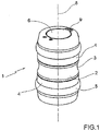
- the cartridges used in the automatic pneumatic conveying system of the cartridges of the invention including that shown in FIG. figure 1 are cylindrical tubular elements 1.
- the element 1 comprises a central cylindrical body 2, with, in the middle part, an annular groove 3, barely hollowed, for gripping the cartridge by an operator.
- the central body 2 is extended axially on both sides by a cover 4 which, here, is screwed on the central body 2.
- each cover 4 On the outer wall of each cover 4 is fixed an annular seal 5 to allow the transport of the cartridge in the tube line of the system under the action of pneumatic pressure.
- Each cover 4 is provided with an opening valve 6 pivotally mounted against the action of a return spring around a small axis orthogonal to the axis 8 of the cartridge by means of a pivot bar 9. In the rest position, each valve 6 closes the cover 4 on which it is mounted and extends in the end plane perpendicular to the cartridge axis 8.
- the valves 6 have a circular disk shape extended by the small pivot bar 9.
- the diameter of the discs substantially corresponds to the outside diameter of a coin slider which will be discussed below and through which the coins can flow by gravity.
- the slide When the slide is lowered, during its course, it rotates the valve 6, from the top of the cartridge in a vertical position, towards the inside of the cartridge to enter the cartridge and allow its filling, it that is, the "harvest" of the pieces.
- the cartridge is symmetrical with respect to a median plane perpendicular to its axis 8 to allow its positioning in the toll terminal in both directions and avoid having to provide keying organs.
- the cartridges have a length adapted to the curves of the line of tubes.
- the used cartridges can receive between 200 and 250 pieces.
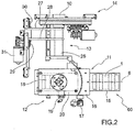
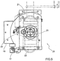
- the terminal of the figure 2 comprises a chute 10 for receiving coins here, a port 11 for input / output of a cartridge, a box 12 for receiving and positioning a cartridge, a slide 13 for the admission of coins, and thus for putting into communication chute 10 with the interior of a cartridge 1 and a valve 14 for retention of coins.
- the trough 10 is the final element of the receiving means of the parts which comprise, as input, a receiving cone, not shown in the drawing.
- the port 11 is the opening of the box 12 through which the tube 15 of the tube line is connected to the box 12 and therefore to the terminal.
- the tube 15, in its connecting portion at least, extends substantially horizontally, without occupying any place under the cabinet 12.
- a mechanical air valve 17 allowing a certain air evacuation and therefore a decrease in the air flow to initiate the braking of the cartridge 1 on arrival in the thick headed.
- the cabinet 12 provides three functions here.
- the first function is the braking of the cartridge.
- the box 12 is equipped with a block 18, a two-component memory foam that brakes the cartridge by damping the shock and minimizing the impact noise of the cartridge in the terminal.
- the air is discharged into the inlet tube 15. Indeed, it is provided with orifices, not visible, over its entire circumference so as to evacuate the air optimally.
- the second function of the cabinet 12 is the detection of the cartridge 1 in the terminal.
- the cabinet 12 is equipped with a reflection optical cell 19 which makes it possible to detect the presence of a cartridge in the terminal.
- a reflection optical cell 19 which makes it possible to detect the presence of a cartridge in the terminal.
- the third function is the positioning of the cartridge for its opening to receive the coins.
- the terminal receives the cartridge 1 in position of horizontal axis ( figure 2 ) and a frame 20 makes it possible to tilt the cartridge 1 in position of vertical axis ( figure 6 ).
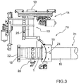
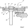
- Frame 20 which we can see better on the figure 3 , is rotatably mounted and therefore comprises an arcuate sector 21 cooperating in rotation with the plate 16 shaped accordingly, the sector 21 being extended by a frame 22 for receiving the cartridge 1.
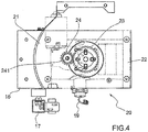
- the rotation of the frame 20 is effected by means of figure 4 ) a gear comprising a gear wheel 23 fixed to the frame 22 and a gear wheel 24 mounted on the axis 24 of a drive motor, not shown in the drawing.
- the tilting of the frame 20 and the cartridge makes it possible to take advantage of the gravity for the collection of the pieces. Thanks to this switchover, we gain a lot of room in mounting the terminal without any portion of line of curved tubes below the terminal, as in that of the prior art.
- the size of the terminal of the invention is particularly small.
- the horizontal and vertical positions of the frame 20 can be determined by sealed Reed contacts, which are end-of-travel contacts with longer life than conventional mechanical contacts.
- the slider 13 itself is in fact a telescopic slider with an outer tube 25 slidably mounted on a fixed inner tube 26, here fixed in the retention valve 14.
- the sliding of the outer tube 25 is effected by means here of a double-armed frame 27, 28 at the inner ends of which is fixed this outer tube 25 and one of the arms 28 carrying at its outer end a gear 29 , cooperating with a rack 30.
- the gear wheel 29 is rotated by a motor 31.
- Reed-type limit switches are also provided.
- the coin intake slide provides two functions.
- the first function is the opening of the automatic cartridge 1.
- the processor of the terminal controls the descent of the outer tube 25 of the slide in the cartridge. This descent causes the opening of the valve 6 of the cartridge 1.
- the processor controls the raising of the outer tube of the slide, which causes the closing of the automatic cartridge 1.
- the outer tube 25 of the slider is guided by a linear guide rail 32 so as to ensure rectilinear movement during movement.
- the second function of the slider 13 is the routing of the parts to the automatic cartridge 1.
- the outer tube of the slider extends the fixed tube in the cartridge. Choosing a larger diameter tube for the sliding part allows continuous guidance of the parts and that without any roughness that could obstruct the passage of coins.
- the valve 43 comprises a rectilinear bore 46 for receiving a roller 47 mounted at the end of a crank 48 rotatably mounted under the action of a valve motor 49.
- a roller 47 mounted at the end of a crank 48 rotatably mounted under the action of a valve motor 49.
- the crank 48 When the crank 48 is rotated by the motor 49, its end roller 47 moves in the bore 46 by driving the valve 43 in displacement in the gap 50, or to close the orifices 44, 45 and thus interrupt the communication between the chute 10 and the inner tube 26 of the slider in the closed position, either to clear the orifices and allow communication between the chute and the inner tube of the slide, in the open position.
- the function of the retention valve 14 is essential because, when returning a solid cartridge to the storage area, it is necessary to wait for the transport time of the full cartridge in one direction and the transport time of a empty cartridge in the opposite direction before being able to "throw” again coins into the empty cartridge properly positioned in the toll terminal. During these two times, the valve must be in the closed position and the parts stored in a buffer zone upstream and not shown in the drawing.
- the toll terminal 60 which has just been described is part of an automatic system 70 for pneumatic conveying cylindrical cartridges 1, gravity receiving coins, a line of cylindrical tubes 71 connecting the terminal 60, and d other, and at least one cartridge entry / exit station and a recipe store.
Landscapes
- Physics & Mathematics (AREA)
- General Physics & Mathematics (AREA)
- Engineering & Computer Science (AREA)
- Fluid Mechanics (AREA)
- Mechanical Engineering (AREA)
- Control Of Vending Devices And Auxiliary Devices For Vending Devices (AREA)
- Branching, Merging, And Special Transfer Between Conveyors (AREA)
- Devices For Checking Fares Or Tickets At Control Points (AREA)
Claims (11)
- Zahlungsendgerät (60) eines Systems (70) zum pneumatischen Transport zylindrischer Kassetten (1) über einen Strang zylindrischer Rohre (71), umfassend:- eine Kassette (1), die dafür bestimmt ist, die Zahlungsmittel zu empfangen,- Empfangsmittel (10) von Zahlungsmitteln, die für einen freien Fall geeignet sind,- einen Eingangs-/Ausgangsanschluss (11) einer Kassette (1), die dafür bestimmt ist, die Zahlungsmittel durch Schwerkraft zu empfangen,- Empfangsmittel (12) einer Kassette (1) und- Mittel (13) zum Inverbindungsetzen der Empfangsmittel (10) der Zahlungsmittel mit dem Inneren einer Kassette (1),- der Eingangs-/Ausgangsanschluss (11) ist angeordnet für den Durchgang einer Kassette (1) in Horizontalachsenposition (8) und- die Kassettenempfangsmittel (12) sind angeordnet, um die Kassette (1) in Vertikalachsenposition (8) zu kippen,- der Eingangs-/Ausgangsanschluss (11) ist die Öffnung der Empfangsmittel (12), durch den sich ein Rohr (15) des Stranges zylindrischer Rohre (71) an die Empfangsmittel (12) und somit an das Endgerät (60) anschließt,- mittels dieses Rohres (15) wird eine leere Kassette (1) im Endgerät vorangetrieben, bevor sie daraus durch den Eingangs-/Ausgangsanschluss (11) ausgestoßen wird, sobald sie voller Zahlungsmittel ist.
- Zahlungsendgerät nach Anspruch 1, wobei die Kassettenempfangsmittel (12) einen Rahmen (20) einschließen, der unter der Einwirkung der Motormittel (24) drehend montiert ist.
- Zahlungsendgerät nach Anspruch 2, wobei der drehende Antrieb des Rahmens (20) mit Hilfe eines Zahnradgetriebes (23, 24) ausgeführt wird.
- Zahlungsendgerät nach einem der Ansprüche 1 bis 3, wobei der Eingangs-/Ausgangsanschluss (11) einer Kassette (1) mit einem Entlüftungsventil (17) ausgestattet ist, das vorgesehen ist, um den Luftdurchsatz zu verringern und somit das Bremsen der Kassette (1) bei ihrer Ankunft im Endgerät einzuleiten.
- Zahlungsendgerät nach einem der Ansprüche 1 bis 4, wobei die Kassettenempfangsmittel (12) angeordnet sind, um die Kassette zu bremsen.
- Zahlungsendgerät nach Anspruch 5, wobei in den Kassettenempfangsmitteln (12) Luftauslassmittel (17) vorgesehen sind, um die Kassette (1) zu bremsen.
- Zahlungsendgerät nach einem der Ansprüche 5 und 6, wobei in den Kassettenempfangsmitteln (12) ein Block (18) mit Zweikomponenten-Gedächtnisschaumstoff vorgesehen ist, um die Kassette (1) zu bremsen.
- Zahlungsendgerät nach einem der Ansprüche 1 bis 7, wobei in den Empfangsmitteln (10) der Zahlungsmittel Mittel (14) zum Zurückhalten der Zahlungsmittel vorgesehen sind, die angeordnet sind, um den Durchgang dieser Zahlungsmittel hin zu den Kassettenempfangsmitteln (12) zu verhindern und so die Mittel (13) zum Inverbindungsetzen der Empfangsmittel (10) der Zahlungsmittel mit dem Inneren einer Kassette (1) zu hemmen.
- Zahlungsendgerät nach einem der Ansprüche 1 bis 8, wobei die Mittel zum Inverbindungsetzen (13) einen teleskopischen Schieber (25, 26) einschließen.
- Zahlungsendgerät nach einem der Ansprüche 1 bis 9, wobei in den Rückhaltemitteln (14) eine Klappe (43) vorgesehen ist, die zwischen den Empfangsmitteln (10) der Zahlungsmittel und den Mitteln zum Inverbindungsetzen (13) verschiebbar montiert ist.
- Automatisches System (70) zum pneumatischen Transport zylindrischer Kassetten (1), zum Empfang von Geldstücken durch Schwerkraft, über einen Strang (71) zylindrischer Rohre, der mindestens ein Zahlungsendgerät (60) nach einem der vorstehenden Ansprüche und Geldstückempfangsendgerät und eine Eingangs-/Ausgangsstation von Kassetten verbindet, dadurch gekennzeichnet, dass der Strang Rohre (71) an das Zahlungsendgerät (60) über einen Abschnitt eines Stranges (15) einer Horizontalachse (8) angeschlossen ist und das Zahlungsendgerät (60) Mittel (12, 20) einschließt, die angeordnet sind, um die Kassetten (1) von einer Horizontalachsenposition (8) in eine Vertikalachsenposition (8) zu kippen.
Applications Claiming Priority (2)
| Application Number | Priority Date | Filing Date | Title |
|---|---|---|---|
| BE2014/0759A BE1022195B1 (fr) | 2014-10-10 | 2014-10-10 | Borne de peage et systeme automatique de transport pneumatique de cartouches comprenant la borne |
| PCT/EP2015/073273 WO2016055575A1 (fr) | 2014-10-10 | 2015-10-08 | Borne de peage et systeme automatique de transport pneumatique de cartouches comprenant la borne |
Publications (2)
| Publication Number | Publication Date |
|---|---|
| EP3204923A1 EP3204923A1 (de) | 2017-08-16 |
| EP3204923B1 true EP3204923B1 (de) | 2019-09-18 |
Family
ID=52745851
Family Applications (1)
| Application Number | Title | Priority Date | Filing Date |
|---|---|---|---|
| EP15775241.1A Not-in-force EP3204923B1 (de) | 2014-10-10 | 2015-10-08 | Zahlungsendgerät und automatisches system zum pneumatischen transport von kassetten mit dem endgerät |
Country Status (4)
| Country | Link |
|---|---|
| EP (1) | EP3204923B1 (de) |
| BE (1) | BE1022195B1 (de) |
| ES (1) | ES2759994T3 (de) |
| WO (1) | WO2016055575A1 (de) |
Family Cites Families (4)
| Publication number | Priority date | Publication date | Assignee | Title |
|---|---|---|---|---|
| GB9204398D0 (en) * | 1992-02-29 | 1992-04-15 | Air Tube Conveyors | Conveyor |
| US5356243A (en) * | 1993-04-21 | 1994-10-18 | Mosler, Inc. | Pivoting tube section for pneumatic transport tube system |
| FR2837480B1 (fr) * | 2002-03-20 | 2004-10-08 | Sncf | Organe de reception et de transfert d'objets pour dispositif de convoyage pneumatique |
| US7341406B1 (en) * | 2005-09-16 | 2008-03-11 | Diebold, Incorporated | Pneumatic transport tube system |
-
2014
- 2014-10-10 BE BE2014/0759A patent/BE1022195B1/fr not_active IP Right Cessation
-
2015
- 2015-10-08 EP EP15775241.1A patent/EP3204923B1/de not_active Not-in-force
- 2015-10-08 ES ES15775241T patent/ES2759994T3/es active Active
- 2015-10-08 WO PCT/EP2015/073273 patent/WO2016055575A1/fr active Application Filing
Non-Patent Citations (1)
| Title |
|---|
| None * |
Also Published As
| Publication number | Publication date |
|---|---|
| EP3204923A1 (de) | 2017-08-16 |
| BE1022195B1 (fr) | 2016-02-26 |
| WO2016055575A1 (fr) | 2016-04-14 |
| ES2759994T3 (es) | 2020-05-12 |
Similar Documents
| Publication | Publication Date | Title |
|---|---|---|
| CA2494436C (fr) | Paroi basculante | |
| EP1935813A1 (de) | Vorrichtung zur Einzelverteilung von Gegenständen in Stäbchenform | |
| EP2705937B1 (de) | Maschine zum Schneiden von Baumstämmen | |
| EP0351295A1 (de) | Münzenverarbeitungsvorrichtung | |
| CA2404148A1 (fr) | Dispositif de tri selectif automatique | |
| EP3204923B1 (de) | Zahlungsendgerät und automatisches system zum pneumatischen transport von kassetten mit dem endgerät | |
| EP0830654B1 (de) | Pneumatischer förderer für metallische kleinteile, insbesondere münzen, mit mehreren zahlungsendgeräten | |
| FR2805126A1 (fr) | Procede de formage d'un corps spherique et dispositif a cette fin | |
| EP0002979A1 (de) | Einrichtung zur automatischen und registrierten Aufbewahrung und Abgabe von Zahlungsmitteln | |
| WO2013079852A1 (fr) | Dispositif pour le deplacement en continu de bouteilles de gaz en direction d'une machine de remplissage | |
| FR3010989A1 (fr) | Installation de dechargement automatique d'objets d'un conteneur | |
| FR2682750A1 (fr) | Magasin de munitions, en particulier pour char. | |
| EP1394517A1 (de) | Dosiermaschine mit einem Zylinder | |
| EP2833928A1 (de) | Kompaktes system zur sterilisation durch elektronenbeschuss | |
| FR2708488A1 (fr) | Dispositif injecteur d'objets dans une machine de tri postal. | |
| EP2358616B1 (de) | Transferstation und verfahren für einen pneumatischen gutträger | |
| FR3094349A1 (fr) | Station de recharge pour drone | |
| FR2852305A1 (fr) | Procede de convoyage de bagages | |
| WO2001051391A1 (fr) | Procede et dispositif de convoyage d'objets en position suspendue | |
| FR2829477A1 (fr) | Dispositif automatique de vidage en continu de caisses ou analogue | |
| CH647299A5 (en) | Automatic dispenser, in particular for banks | |
| FR2669611A1 (fr) | Installation de triage de pieces. | |
| FR3086933A1 (fr) | Dispositif de transfert pour convoyeur | |
| FR2733202A1 (fr) | Dispositif de separation a l'unite de produits juxtaposes ou ampiles | |
| CH482610A (fr) | Procédé et dispositif de transport pneumatique de pièces |
Legal Events
| Date | Code | Title | Description |
|---|---|---|---|
| STAA | Information on the status of an ep patent application or granted ep patent |
Free format text: STATUS: THE INTERNATIONAL PUBLICATION HAS BEEN MADE |
|
| PUAI | Public reference made under article 153(3) epc to a published international application that has entered the european phase |
Free format text: ORIGINAL CODE: 0009012 |
|
| STAA | Information on the status of an ep patent application or granted ep patent |
Free format text: STATUS: REQUEST FOR EXAMINATION WAS MADE |
|
| 17P | Request for examination filed |
Effective date: 20170309 |
|
| AK | Designated contracting states |
Kind code of ref document: A1 Designated state(s): AL AT BE BG CH CY CZ DE DK EE ES FI FR GB GR HR HU IE IS IT LI LT LU LV MC MK MT NL NO PL PT RO RS SE SI SK SM TR |
|
| AX | Request for extension of the european patent |
Extension state: BA ME |
|
| DAV | Request for validation of the european patent (deleted) | ||
| DAX | Request for extension of the european patent (deleted) | ||
| GRAP | Despatch of communication of intention to grant a patent |
Free format text: ORIGINAL CODE: EPIDOSNIGR1 |
|
| STAA | Information on the status of an ep patent application or granted ep patent |
Free format text: STATUS: GRANT OF PATENT IS INTENDED |
|
| INTG | Intention to grant announced |
Effective date: 20190416 |
|
| GRAS | Grant fee paid |
Free format text: ORIGINAL CODE: EPIDOSNIGR3 |
|
| GRAA | (expected) grant |
Free format text: ORIGINAL CODE: 0009210 |
|
| STAA | Information on the status of an ep patent application or granted ep patent |
Free format text: STATUS: THE PATENT HAS BEEN GRANTED |
|
| AK | Designated contracting states |
Kind code of ref document: B1 Designated state(s): AL AT BE BG CH CY CZ DE DK EE ES FI FR GB GR HR HU IE IS IT LI LT LU LV MC MK MT NL NO PL PT RO RS SE SI SK SM TR |
|
| REG | Reference to a national code |
Ref country code: GB Ref legal event code: FG4D Free format text: NOT ENGLISH |
|
| REG | Reference to a national code |
Ref country code: CH Ref legal event code: EP |
|
| REG | Reference to a national code |
Ref country code: DE Ref legal event code: R096 Ref document number: 602015038297 Country of ref document: DE |
|
| REG | Reference to a national code |
Ref country code: AT Ref legal event code: REF Ref document number: 1182218 Country of ref document: AT Kind code of ref document: T Effective date: 20191015 |
|
| REG | Reference to a national code |
Ref country code: IE Ref legal event code: FG4D Free format text: LANGUAGE OF EP DOCUMENT: FRENCH |
|
| REG | Reference to a national code |
Ref country code: NL Ref legal event code: FP |
|
| REG | Reference to a national code |
Ref country code: CH Ref legal event code: NV Representative=s name: NOVAGRAAF INTERNATIONAL SA, CH |
|
| PG25 | Lapsed in a contracting state [announced via postgrant information from national office to epo] |
Ref country code: FI Free format text: LAPSE BECAUSE OF FAILURE TO SUBMIT A TRANSLATION OF THE DESCRIPTION OR TO PAY THE FEE WITHIN THE PRESCRIBED TIME-LIMIT Effective date: 20190918 Ref country code: LT Free format text: LAPSE BECAUSE OF FAILURE TO SUBMIT A TRANSLATION OF THE DESCRIPTION OR TO PAY THE FEE WITHIN THE PRESCRIBED TIME-LIMIT Effective date: 20190918 Ref country code: BG Free format text: LAPSE BECAUSE OF FAILURE TO SUBMIT A TRANSLATION OF THE DESCRIPTION OR TO PAY THE FEE WITHIN THE PRESCRIBED TIME-LIMIT Effective date: 20191218 Ref country code: NO Free format text: LAPSE BECAUSE OF FAILURE TO SUBMIT A TRANSLATION OF THE DESCRIPTION OR TO PAY THE FEE WITHIN THE PRESCRIBED TIME-LIMIT Effective date: 20191218 Ref country code: HR Free format text: LAPSE BECAUSE OF FAILURE TO SUBMIT A TRANSLATION OF THE DESCRIPTION OR TO PAY THE FEE WITHIN THE PRESCRIBED TIME-LIMIT Effective date: 20190918 Ref country code: SE Free format text: LAPSE BECAUSE OF FAILURE TO SUBMIT A TRANSLATION OF THE DESCRIPTION OR TO PAY THE FEE WITHIN THE PRESCRIBED TIME-LIMIT Effective date: 20190918 |
|
| REG | Reference to a national code |
Ref country code: LT Ref legal event code: MG4D |
|
| PG25 | Lapsed in a contracting state [announced via postgrant information from national office to epo] |
Ref country code: RS Free format text: LAPSE BECAUSE OF FAILURE TO SUBMIT A TRANSLATION OF THE DESCRIPTION OR TO PAY THE FEE WITHIN THE PRESCRIBED TIME-LIMIT Effective date: 20190918 Ref country code: AL Free format text: LAPSE BECAUSE OF FAILURE TO SUBMIT A TRANSLATION OF THE DESCRIPTION OR TO PAY THE FEE WITHIN THE PRESCRIBED TIME-LIMIT Effective date: 20190918 Ref country code: GR Free format text: LAPSE BECAUSE OF FAILURE TO SUBMIT A TRANSLATION OF THE DESCRIPTION OR TO PAY THE FEE WITHIN THE PRESCRIBED TIME-LIMIT Effective date: 20191219 Ref country code: LV Free format text: LAPSE BECAUSE OF FAILURE TO SUBMIT A TRANSLATION OF THE DESCRIPTION OR TO PAY THE FEE WITHIN THE PRESCRIBED TIME-LIMIT Effective date: 20190918 |
|
| PG25 | Lapsed in a contracting state [announced via postgrant information from national office to epo] |
Ref country code: RO Free format text: LAPSE BECAUSE OF FAILURE TO SUBMIT A TRANSLATION OF THE DESCRIPTION OR TO PAY THE FEE WITHIN THE PRESCRIBED TIME-LIMIT Effective date: 20190918 Ref country code: PL Free format text: LAPSE BECAUSE OF FAILURE TO SUBMIT A TRANSLATION OF THE DESCRIPTION OR TO PAY THE FEE WITHIN THE PRESCRIBED TIME-LIMIT Effective date: 20190918 Ref country code: EE Free format text: LAPSE BECAUSE OF FAILURE TO SUBMIT A TRANSLATION OF THE DESCRIPTION OR TO PAY THE FEE WITHIN THE PRESCRIBED TIME-LIMIT Effective date: 20190918 Ref country code: PT Free format text: LAPSE BECAUSE OF FAILURE TO SUBMIT A TRANSLATION OF THE DESCRIPTION OR TO PAY THE FEE WITHIN THE PRESCRIBED TIME-LIMIT Effective date: 20200120 |
|
| REG | Reference to a national code |
Ref country code: ES Ref legal event code: FG2A Ref document number: 2759994 Country of ref document: ES Kind code of ref document: T3 Effective date: 20200512 |
|
| PG25 | Lapsed in a contracting state [announced via postgrant information from national office to epo] |
Ref country code: SK Free format text: LAPSE BECAUSE OF FAILURE TO SUBMIT A TRANSLATION OF THE DESCRIPTION OR TO PAY THE FEE WITHIN THE PRESCRIBED TIME-LIMIT Effective date: 20190918 Ref country code: CZ Free format text: LAPSE BECAUSE OF FAILURE TO SUBMIT A TRANSLATION OF THE DESCRIPTION OR TO PAY THE FEE WITHIN THE PRESCRIBED TIME-LIMIT Effective date: 20190918 Ref country code: IS Free format text: LAPSE BECAUSE OF FAILURE TO SUBMIT A TRANSLATION OF THE DESCRIPTION OR TO PAY THE FEE WITHIN THE PRESCRIBED TIME-LIMIT Effective date: 20200224 Ref country code: SM Free format text: LAPSE BECAUSE OF FAILURE TO SUBMIT A TRANSLATION OF THE DESCRIPTION OR TO PAY THE FEE WITHIN THE PRESCRIBED TIME-LIMIT Effective date: 20190918 |
|
| REG | Reference to a national code |
Ref country code: DE Ref legal event code: R097 Ref document number: 602015038297 Country of ref document: DE |
|
| PLBE | No opposition filed within time limit |
Free format text: ORIGINAL CODE: 0009261 |
|
| STAA | Information on the status of an ep patent application or granted ep patent |
Free format text: STATUS: NO OPPOSITION FILED WITHIN TIME LIMIT |
|
| PG2D | Information on lapse in contracting state deleted |
Ref country code: IS |
|
| PG25 | Lapsed in a contracting state [announced via postgrant information from national office to epo] |
Ref country code: LU Free format text: LAPSE BECAUSE OF NON-PAYMENT OF DUE FEES Effective date: 20191008 Ref country code: DK Free format text: LAPSE BECAUSE OF FAILURE TO SUBMIT A TRANSLATION OF THE DESCRIPTION OR TO PAY THE FEE WITHIN THE PRESCRIBED TIME-LIMIT Effective date: 20190918 Ref country code: IS Free format text: LAPSE BECAUSE OF FAILURE TO SUBMIT A TRANSLATION OF THE DESCRIPTION OR TO PAY THE FEE WITHIN THE PRESCRIBED TIME-LIMIT Effective date: 20200119 |
|
| 26N | No opposition filed |
Effective date: 20200619 |
|
| PG25 | Lapsed in a contracting state [announced via postgrant information from national office to epo] |
Ref country code: SI Free format text: LAPSE BECAUSE OF FAILURE TO SUBMIT A TRANSLATION OF THE DESCRIPTION OR TO PAY THE FEE WITHIN THE PRESCRIBED TIME-LIMIT Effective date: 20190918 Ref country code: MC Free format text: LAPSE BECAUSE OF FAILURE TO SUBMIT A TRANSLATION OF THE DESCRIPTION OR TO PAY THE FEE WITHIN THE PRESCRIBED TIME-LIMIT Effective date: 20190918 |
|
| PG25 | Lapsed in a contracting state [announced via postgrant information from national office to epo] |
Ref country code: IE Free format text: LAPSE BECAUSE OF NON-PAYMENT OF DUE FEES Effective date: 20191008 |
|
| PG25 | Lapsed in a contracting state [announced via postgrant information from national office to epo] |
Ref country code: CY Free format text: LAPSE BECAUSE OF FAILURE TO SUBMIT A TRANSLATION OF THE DESCRIPTION OR TO PAY THE FEE WITHIN THE PRESCRIBED TIME-LIMIT Effective date: 20190918 |
|
| PG25 | Lapsed in a contracting state [announced via postgrant information from national office to epo] |
Ref country code: MT Free format text: LAPSE BECAUSE OF FAILURE TO SUBMIT A TRANSLATION OF THE DESCRIPTION OR TO PAY THE FEE WITHIN THE PRESCRIBED TIME-LIMIT Effective date: 20190918 Ref country code: HU Free format text: LAPSE BECAUSE OF FAILURE TO SUBMIT A TRANSLATION OF THE DESCRIPTION OR TO PAY THE FEE WITHIN THE PRESCRIBED TIME-LIMIT; INVALID AB INITIO Effective date: 20151008 |
|
| PGFP | Annual fee paid to national office [announced via postgrant information from national office to epo] |
Ref country code: NL Payment date: 20211027 Year of fee payment: 7 |
|
| PGFP | Annual fee paid to national office [announced via postgrant information from national office to epo] |
Ref country code: AT Payment date: 20211006 Year of fee payment: 7 Ref country code: GB Payment date: 20211019 Year of fee payment: 7 Ref country code: ES Payment date: 20211115 Year of fee payment: 7 Ref country code: DE Payment date: 20211007 Year of fee payment: 7 |
|
| PGFP | Annual fee paid to national office [announced via postgrant information from national office to epo] |
Ref country code: IT Payment date: 20211008 Year of fee payment: 7 Ref country code: FR Payment date: 20211027 Year of fee payment: 7 Ref country code: CH Payment date: 20211013 Year of fee payment: 7 Ref country code: BE Payment date: 20211027 Year of fee payment: 7 |
|
| PG25 | Lapsed in a contracting state [announced via postgrant information from national office to epo] |
Ref country code: TR Free format text: LAPSE BECAUSE OF FAILURE TO SUBMIT A TRANSLATION OF THE DESCRIPTION OR TO PAY THE FEE WITHIN THE PRESCRIBED TIME-LIMIT Effective date: 20190918 |
|
| PG25 | Lapsed in a contracting state [announced via postgrant information from national office to epo] |
Ref country code: MK Free format text: LAPSE BECAUSE OF FAILURE TO SUBMIT A TRANSLATION OF THE DESCRIPTION OR TO PAY THE FEE WITHIN THE PRESCRIBED TIME-LIMIT Effective date: 20190918 |
|
| REG | Reference to a national code |
Ref country code: DE Ref legal event code: R119 Ref document number: 602015038297 Country of ref document: DE |
|
| REG | Reference to a national code |
Ref country code: CH Ref legal event code: PL |
|
| REG | Reference to a national code |
Ref country code: NL Ref legal event code: MM Effective date: 20221101 |
|
| P01 | Opt-out of the competence of the unified patent court (upc) registered |
Effective date: 20230428 |
|
| REG | Reference to a national code |
Ref country code: AT Ref legal event code: MM01 Ref document number: 1182218 Country of ref document: AT Kind code of ref document: T Effective date: 20221008 |
|
| REG | Reference to a national code |
Ref country code: BE Ref legal event code: MM Effective date: 20221031 |
|
| GBPC | Gb: european patent ceased through non-payment of renewal fee |
Effective date: 20221008 |
|
| PG25 | Lapsed in a contracting state [announced via postgrant information from national office to epo] |
Ref country code: NL Free format text: LAPSE BECAUSE OF NON-PAYMENT OF DUE FEES Effective date: 20221101 Ref country code: LI Free format text: LAPSE BECAUSE OF NON-PAYMENT OF DUE FEES Effective date: 20221031 Ref country code: FR Free format text: LAPSE BECAUSE OF NON-PAYMENT OF DUE FEES Effective date: 20221031 Ref country code: DE Free format text: LAPSE BECAUSE OF NON-PAYMENT OF DUE FEES Effective date: 20230503 Ref country code: CH Free format text: LAPSE BECAUSE OF NON-PAYMENT OF DUE FEES Effective date: 20221031 Ref country code: AT Free format text: LAPSE BECAUSE OF NON-PAYMENT OF DUE FEES Effective date: 20221008 |
|
| PG25 | Lapsed in a contracting state [announced via postgrant information from national office to epo] |
Ref country code: BE Free format text: LAPSE BECAUSE OF NON-PAYMENT OF DUE FEES Effective date: 20221031 |
|
| PG25 | Lapsed in a contracting state [announced via postgrant information from national office to epo] |
Ref country code: IT Free format text: LAPSE BECAUSE OF NON-PAYMENT OF DUE FEES Effective date: 20221008 Ref country code: GB Free format text: LAPSE BECAUSE OF NON-PAYMENT OF DUE FEES Effective date: 20221008 |
|
| REG | Reference to a national code |
Ref country code: ES Ref legal event code: FD2A Effective date: 20231127 |
|
| PG25 | Lapsed in a contracting state [announced via postgrant information from national office to epo] |
Ref country code: ES Free format text: LAPSE BECAUSE OF NON-PAYMENT OF DUE FEES Effective date: 20221009 |
|
| PG25 | Lapsed in a contracting state [announced via postgrant information from national office to epo] |
Ref country code: ES Free format text: LAPSE BECAUSE OF NON-PAYMENT OF DUE FEES Effective date: 20221009 |