EP3204923B1 - Payment terminal and automatic system for pneumatically transporting cartridges comprising the terminal - Google Patents
Payment terminal and automatic system for pneumatically transporting cartridges comprising the terminal Download PDFInfo
- Publication number
- EP3204923B1 EP3204923B1 EP15775241.1A EP15775241A EP3204923B1 EP 3204923 B1 EP3204923 B1 EP 3204923B1 EP 15775241 A EP15775241 A EP 15775241A EP 3204923 B1 EP3204923 B1 EP 3204923B1
- Authority
- EP
- European Patent Office
- Prior art keywords
- cartridge
- receiving
- payment
- toll terminal
- toll
- Prior art date
- Legal status (The legal status is an assumption and is not a legal conclusion. Google has not performed a legal analysis and makes no representation as to the accuracy of the status listed.)
- Not-in-force
Links
- 230000005484 gravity Effects 0.000 claims description 7
- 229920000079 Memory foam Polymers 0.000 claims description 2
- 239000008210 memory foam Substances 0.000 claims description 2
- 230000006870 function Effects 0.000 description 8
- 230000014759 maintenance of location Effects 0.000 description 4
- 210000000056 organ Anatomy 0.000 description 3
- 238000006073 displacement reaction Methods 0.000 description 2
- 230000003287 optical effect Effects 0.000 description 2
- 239000007787 solid Substances 0.000 description 2
- 235000014676 Phragmites communis Nutrition 0.000 description 1
- 230000005540 biological transmission Effects 0.000 description 1
- 238000010276 construction Methods 0.000 description 1
- 238000013016 damping Methods 0.000 description 1
- 238000001514 detection method Methods 0.000 description 1
- 238000003306 harvesting Methods 0.000 description 1
- 238000013017 mechanical damping Methods 0.000 description 1
- 230000000750 progressive effect Effects 0.000 description 1
- 230000035939 shock Effects 0.000 description 1
- 238000011144 upstream manufacturing Methods 0.000 description 1
Images

Classifications
-
- G—PHYSICS
- G07—CHECKING-DEVICES
- G07D—HANDLING OF COINS OR VALUABLE PAPERS, e.g. TESTING, SORTING BY DENOMINATIONS, COUNTING, DISPENSING, CHANGING OR DEPOSITING
- G07D11/00—Devices accepting coins; Devices accepting, dispensing, sorting or counting valuable papers
- G07D11/009—Depositing devices
- G07D11/0096—Accepting paper currency or other valuables in containers, e.g. in code-marked envelopes
-
- B—PERFORMING OPERATIONS; TRANSPORTING
- B65—CONVEYING; PACKING; STORING; HANDLING THIN OR FILAMENTARY MATERIAL
- B65G—TRANSPORT OR STORAGE DEVICES, e.g. CONVEYORS FOR LOADING OR TIPPING, SHOP CONVEYOR SYSTEMS OR PNEUMATIC TUBE CONVEYORS
- B65G51/00—Conveying articles through pipes or tubes by fluid flow or pressure; Conveying articles over a flat surface, e.g. the base of a trough, by jets located in the surface
- B65G51/04—Conveying the articles in carriers having a cross-section approximating that of the pipe or tube; Tube mail systems
- B65G51/26—Stations
-
- G—PHYSICS
- G07—CHECKING-DEVICES
- G07D—HANDLING OF COINS OR VALUABLE PAPERS, e.g. TESTING, SORTING BY DENOMINATIONS, COUNTING, DISPENSING, CHANGING OR DEPOSITING
- G07D11/00—Devices accepting coins; Devices accepting, dispensing, sorting or counting valuable papers
- G07D11/10—Mechanical details
Definitions
- the field of the invention is essentially, but not exclusively, the toll by pieces or payment tokens that are introduced, or even thrown, to toll terminals in cartridges. It is necessary to feed the terminals in empty cartridges, generally from a cartridge store, and the full cartridges must be evacuated on a secure temporary storage of coins and tokens, including safe, where they are emptied.
- Cartridges, empty or full, are transported in a line of cylindrical pneumatic conveying tubes.
- the cartridges are accordingly shaped and are therefore also cylindrical, with an outer diameter substantially equal to the inner diameter of the transport tubes.
- WO93 / 16943 discloses a pneumatic tube conveyor comprising: a sending station (12) at which a carrier (14) enters the conveyor, and an elongated carrier tube (11) extending from the sending station and wherein is conveyed the wearer.
- a tubular region located in the sending station has an elongated empty space (21) in its wall, the length of which corresponds to the width of the wearer, the sending station having an intake element spaced laterally from the axis of the carrier. said tubular region to allow the introduction of a carrier.
- the sending station is designed to carry a carrier introduced by the intake element, laterally with respect to the axis of the tubular region, and to allow the introduction of the carrier in an orientation substantially parallel to the axis of the tubular region by the empty space, to bring said carrier into said tubular region.
- the document US5356243 discloses a pneumatic conveying system with a vertical transport tube section that pivots about an upper horizontal axis to move the cartridge between the vertical send / receive position and an oblique but generally vertical presentation position.
- Such pneumatic conveying systems can be installed in motorway toll gates, which are provided with technical galleries for this purpose. If the highway toll is therefore a fundamental application of the invention of the present application, it is certainly not an application that must be considered as limiting. Wherever customers or users must pay with coins or tokens, or any other means of payment of a certain weight and susceptible to a free fall, the invention may be considered. This is the case of parking areas, supermarkets, casinos, etc.
- the cartridges are driven in displacement in the tubes in a direction parallel to their axis, which direction is generally horizontal.
- the cartridge at a toll terminal, in the position of use, that is to say the receipt of coins, the cartridge must have its vertical axis so that the parts can enter the terminal by gravity. This is in any case the adapted arrangement in existing systems.
- chutes or other particular devices for introducing parts are excluded for reasons of space and cost.
- the first is related to the size of the terminals in which we must be able to house a portion of the curve portion. It is made here mainly reference to the vertical space and it is a big disadvantage when the technical galleries can not be too buried.
- the second problem is the wear of these curved line portions inexorably caused by the repeated passages of the cartridges.
- the invention of the present application therefore aims to propose a system in which the curved portions of pneumatic conveying lines of cartridges near the toll terminals have disappeared.
- the invention is defined by claim 1.
- the invention is remarkable in that it is at the end of a very long period of partial and progressive tilting of the axis of the cartridges that we dared to propose a pure and simple tilting of the cartridges themselves to the inside the toll terminals, thus saving a lot of space at the terminals and ensuring better transport of the cartridges between the different treatment stations.
- the cartridge receiving means comprise a frame rotatably mounted under the action of motor means; advantageously, the rotation of the frame is effected by means of a gear with toothed wheels.
- the cartridge inlet / outlet port is equipped with an air discharge valve provided to decrease the air flow and thus initiate the braking of the cartridge upon arrival in the terminal.
- the cartridge receiving means are arranged to brake the cartridge using, for example, air exhaust means and mechanical damping means.
- the invention also relates to an automatic pneumatic conveying system for cylindrical cartridges, receiving by gravity of coins by a line of cylindrical tubes connecting at least one terminal for toll and receipt of coins and an entry station / cartridge outlet, characterized in that the line of tubes is connected to the toll terminal by a portion of line of horizontal axis and the toll terminal comprises means arranged to tilt the cartridges of a horizontal axis position at a position of vertical axis.
- cartridge entry / exit station By cartridge entry / exit station, one can hear a station in which cartridges, empty or full, are stacked on top of each other, to serve as a source of power or storage before emptying the cartridges. It can also be a recipe store or secure vault. In short, it is any cabinet or cabinet that can be found on an automated area of all channels payments (VTP).
- VTP automated area of all channels payments
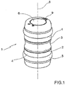
- the cartridges used in the automatic pneumatic conveying system of the cartridges of the invention including that shown in FIG. figure 1 are cylindrical tubular elements 1.
- the element 1 comprises a central cylindrical body 2, with, in the middle part, an annular groove 3, barely hollowed, for gripping the cartridge by an operator.
- the central body 2 is extended axially on both sides by a cover 4 which, here, is screwed on the central body 2.
- each cover 4 On the outer wall of each cover 4 is fixed an annular seal 5 to allow the transport of the cartridge in the tube line of the system under the action of pneumatic pressure.
- Each cover 4 is provided with an opening valve 6 pivotally mounted against the action of a return spring around a small axis orthogonal to the axis 8 of the cartridge by means of a pivot bar 9. In the rest position, each valve 6 closes the cover 4 on which it is mounted and extends in the end plane perpendicular to the cartridge axis 8.
- the valves 6 have a circular disk shape extended by the small pivot bar 9.
- the diameter of the discs substantially corresponds to the outside diameter of a coin slider which will be discussed below and through which the coins can flow by gravity.
- the slide When the slide is lowered, during its course, it rotates the valve 6, from the top of the cartridge in a vertical position, towards the inside of the cartridge to enter the cartridge and allow its filling, it that is, the "harvest" of the pieces.
- the cartridge is symmetrical with respect to a median plane perpendicular to its axis 8 to allow its positioning in the toll terminal in both directions and avoid having to provide keying organs.
- the cartridges have a length adapted to the curves of the line of tubes.
- the used cartridges can receive between 200 and 250 pieces.
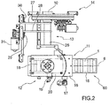
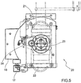
- the terminal of the figure 2 comprises a chute 10 for receiving coins here, a port 11 for input / output of a cartridge, a box 12 for receiving and positioning a cartridge, a slide 13 for the admission of coins, and thus for putting into communication chute 10 with the interior of a cartridge 1 and a valve 14 for retention of coins.
- the trough 10 is the final element of the receiving means of the parts which comprise, as input, a receiving cone, not shown in the drawing.
- the port 11 is the opening of the box 12 through which the tube 15 of the tube line is connected to the box 12 and therefore to the terminal.
- the tube 15, in its connecting portion at least, extends substantially horizontally, without occupying any place under the cabinet 12.
- a mechanical air valve 17 allowing a certain air evacuation and therefore a decrease in the air flow to initiate the braking of the cartridge 1 on arrival in the thick headed.
- the cabinet 12 provides three functions here.
- the first function is the braking of the cartridge.
- the box 12 is equipped with a block 18, a two-component memory foam that brakes the cartridge by damping the shock and minimizing the impact noise of the cartridge in the terminal.
- the air is discharged into the inlet tube 15. Indeed, it is provided with orifices, not visible, over its entire circumference so as to evacuate the air optimally.
- the second function of the cabinet 12 is the detection of the cartridge 1 in the terminal.
- the cabinet 12 is equipped with a reflection optical cell 19 which makes it possible to detect the presence of a cartridge in the terminal.
- a reflection optical cell 19 which makes it possible to detect the presence of a cartridge in the terminal.
- the third function is the positioning of the cartridge for its opening to receive the coins.
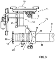
- the terminal receives the cartridge 1 in position of horizontal axis ( figure 2 ) and a frame 20 makes it possible to tilt the cartridge 1 in position of vertical axis ( figure 6 ).
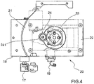
- Frame 20 which we can see better on the figure 3 , is rotatably mounted and therefore comprises an arcuate sector 21 cooperating in rotation with the plate 16 shaped accordingly, the sector 21 being extended by a frame 22 for receiving the cartridge 1.
- the rotation of the frame 20 is effected by means of figure 4 ) a gear comprising a gear wheel 23 fixed to the frame 22 and a gear wheel 24 mounted on the axis 24 of a drive motor, not shown in the drawing.
- the tilting of the frame 20 and the cartridge makes it possible to take advantage of the gravity for the collection of the pieces. Thanks to this switchover, we gain a lot of room in mounting the terminal without any portion of line of curved tubes below the terminal, as in that of the prior art.
- the size of the terminal of the invention is particularly small.
- the horizontal and vertical positions of the frame 20 can be determined by sealed Reed contacts, which are end-of-travel contacts with longer life than conventional mechanical contacts.
- the slider 13 itself is in fact a telescopic slider with an outer tube 25 slidably mounted on a fixed inner tube 26, here fixed in the retention valve 14.
- the sliding of the outer tube 25 is effected by means here of a double-armed frame 27, 28 at the inner ends of which is fixed this outer tube 25 and one of the arms 28 carrying at its outer end a gear 29 , cooperating with a rack 30.
- the gear wheel 29 is rotated by a motor 31.
- Reed-type limit switches are also provided.
- the coin intake slide provides two functions.
- the first function is the opening of the automatic cartridge 1.
- the processor of the terminal controls the descent of the outer tube 25 of the slide in the cartridge. This descent causes the opening of the valve 6 of the cartridge 1.
- the processor controls the raising of the outer tube of the slide, which causes the closing of the automatic cartridge 1.
- the outer tube 25 of the slider is guided by a linear guide rail 32 so as to ensure rectilinear movement during movement.
- the second function of the slider 13 is the routing of the parts to the automatic cartridge 1.
- the outer tube of the slider extends the fixed tube in the cartridge. Choosing a larger diameter tube for the sliding part allows continuous guidance of the parts and that without any roughness that could obstruct the passage of coins.
- the valve 43 comprises a rectilinear bore 46 for receiving a roller 47 mounted at the end of a crank 48 rotatably mounted under the action of a valve motor 49.
- a roller 47 mounted at the end of a crank 48 rotatably mounted under the action of a valve motor 49.
- the crank 48 When the crank 48 is rotated by the motor 49, its end roller 47 moves in the bore 46 by driving the valve 43 in displacement in the gap 50, or to close the orifices 44, 45 and thus interrupt the communication between the chute 10 and the inner tube 26 of the slider in the closed position, either to clear the orifices and allow communication between the chute and the inner tube of the slide, in the open position.
- the function of the retention valve 14 is essential because, when returning a solid cartridge to the storage area, it is necessary to wait for the transport time of the full cartridge in one direction and the transport time of a empty cartridge in the opposite direction before being able to "throw” again coins into the empty cartridge properly positioned in the toll terminal. During these two times, the valve must be in the closed position and the parts stored in a buffer zone upstream and not shown in the drawing.
- the toll terminal 60 which has just been described is part of an automatic system 70 for pneumatic conveying cylindrical cartridges 1, gravity receiving coins, a line of cylindrical tubes 71 connecting the terminal 60, and d other, and at least one cartridge entry / exit station and a recipe store.
Description
Le domaine de l'invention est essentiellement, mais non exclusivement, le péage par pièces ou jetons de paiement qu'on introduit, voire même qu'on jette, à des bornes de péage dans des cartouches. Il faut alimenter les bornes en cartouches vides, généralement à partir d'un stockeur de cartouches, et les cartouches pleines doivent être évacuées sur un poste sécurisé de stockage temporaire des pièces et jetons, de type coffre-fort notamment, où elles sont vidées. Le transport des cartouches, vides ou pleines, s'effectue dans une ligne de tubes cylindriques de transport pneumatique. Les cartouches sont conformées en conséquent et sont donc également cylindriques, d'un diamètre externe sensiblement égal au diamètre interne des tubes de transport.The field of the invention is essentially, but not exclusively, the toll by pieces or payment tokens that are introduced, or even thrown, to toll terminals in cartridges. It is necessary to feed the terminals in empty cartridges, generally from a cartridge store, and the full cartridges must be evacuated on a secure temporary storage of coins and tokens, including safe, where they are emptied. Cartridges, empty or full, are transported in a line of cylindrical pneumatic conveying tubes. The cartridges are accordingly shaped and are therefore also cylindrical, with an outer diameter substantially equal to the inner diameter of the transport tubes.
Le document
De tels systèmes de transport pneumatique peuvent être implantés dans des barrières de péage d'autoroute, qui sont pourvues de galeries techniques à cet effet. Si le péage autoroutier est donc une application fondamentale de l'invention de la présente demande, ce n'est assurément pas une application qu'il faut considérer comme limitative. Partout où des clients ou usagers doivent payer avec des pièces ou des jetons, ou tous autres moyens de paiement d'un certain poids et susceptibles d'une chute libre, l'invention peut être envisagée. Il en est ainsi des zones de parking, des grandes surfaces commerciales, des casinos, etc.Such pneumatic conveying systems can be installed in motorway toll gates, which are provided with technical galleries for this purpose. If the highway toll is therefore a fundamental application of the invention of the present application, it is certainly not an application that must be considered as limiting. Wherever customers or users must pay with coins or tokens, or any other means of payment of a certain weight and susceptible to a free fall, the invention may be considered. This is the case of parking areas, supermarkets, casinos, etc.
Par construction, les cartouches sont entraînées en déplacement dans les tubes dans une direction parallèle à leur axe, direction qui est en général horizontale.By construction, the cartridges are driven in displacement in the tubes in a direction parallel to their axis, which direction is generally horizontal.
Mais à une borne de péage, en position d'utilisation, c'est-à-dire de réception de pièces, la cartouche doit avoir son axe vertical pour que les pièces puissent entrer dans la borne par gravité. C'est en tout cas la disposition adaptée dans les systèmes existants.But at a toll terminal, in the position of use, that is to say the receipt of coins, the cartridge must have its vertical axis so that the parts can enter the terminal by gravity. This is in any case the adapted arrangement in existing systems.
L'adoption de goulottes ou autres dispositifs particuliers d'introduction de pièces est exclue pour des raisons d'encombrement et de coût.The adoption of chutes or other particular devices for introducing parts is excluded for reasons of space and cost.
Les systèmes actuellement installés ou proposés, et ils le sont depuis fort longtemps - trente ans ou plus -, prévoient donc, à l'approche d'une borne de péage, un basculement de l'axe des cartouches en position verticale par l'intermédiaire d'une portion courbe de la ligne de tubes, d'un rayon de courbure forcément non négligeable, compte tenu du diamètre des tubes utilisés.The systems currently installed or proposed, and they have been for a long time - thirty years or more -, therefore provide, when approaching a toll terminal, a tilting of the axis of the cartridges in vertical position via a curved portion of the tube line, a radius of curvature necessarily significant, given the diameter of the tubes used.
Cette courbure de la ligne de transport à l'entrée des bornes de péage pose deux problèmes.This curvature of the transmission line at the entrance to the toll terminals poses two problems.
Le premier est relatif à l'encombrement des bornes dans lesquelles on doit pouvoir loger une partie de la portion de courbe. Il est fait ici essentiellement référence à l'encombrement vertical et c'est un gros inconvénient quand les galeries techniques ne peuvent pas être trop enterrées.The first is related to the size of the terminals in which we must be able to house a portion of the curve portion. It is made here mainly reference to the vertical space and it is a big disadvantage when the technical galleries can not be too buried.
Le deuxième problème est l'usure de ces portions courbes de ligne inexorablement provoqué par les passages répétés des cartouches.The second problem is the wear of these curved line portions inexorably caused by the repeated passages of the cartridges.
L'invention de la présente demande vise donc à proposer un système dans lequel les portions courbes de ligne de transport pneumatique de cartouches à l'approche des bornes de péage ont disparu.The invention of the present application therefore aims to propose a system in which the curved portions of pneumatic conveying lines of cartridges near the toll terminals have disappeared.
L'invention est définie par la revendication 1.The invention is defined by
L'invention est remarquable par le fait que c'est au terme d'une très longue période de basculement partiel et progressif de l'axe des cartouches qu'on a osé proposer un basculement pur et simple des cartouches elles-mêmes à l'intérieur des bornes de péage, gagnant ainsi beaucoup de place au niveau des bornes et assurant un meilleur transport des cartouches entre les différents postes de traitement.The invention is remarkable in that it is at the end of a very long period of partial and progressive tilting of the axis of the cartridges that we dared to propose a pure and simple tilting of the cartridges themselves to the inside the toll terminals, thus saving a lot of space at the terminals and ensuring better transport of the cartridges between the different treatment stations.
Par positions ou directions horizontale et verticale de l'axe des cartouches, on doit entendre des directions qui pourraient ne pas être rigoureusement horizontale ou verticale, selon les contraintes de mise en oeuvre des équipements.By positions or horizontal and vertical directions of the axis of the cartridges, one must hear directions that might not be strictly horizontal or vertical, depending on the constraints of implementation of the equipment.
Dans la forme de réalisation préférée de la borne de l'invention, les moyens de réception de cartouche comportent un cadre monté rotatif sous l'action de moyens moteurs ; avantageusement, l'entraînement en rotation du cadre s'effectue par l'intermédiaire d'un engrenage à roues dentées.In the preferred embodiment of the terminal of the invention, the cartridge receiving means comprise a frame rotatably mounted under the action of motor means; advantageously, the rotation of the frame is effected by means of a gear with toothed wheels.
De préférence encore, le port d'entrée / sortie de cartouche est équipé d'une soupape d'évacuation d'air prévue pour diminuer le débit d'air et donc amorcer le freinage de la cartouche à son arrivée dans la borne.More preferably, the cartridge inlet / outlet port is equipped with an air discharge valve provided to decrease the air flow and thus initiate the braking of the cartridge upon arrival in the terminal.
Avantageusement encore, les moyens de réception de cartouche sont agencés pour freiner la cartouche à l'aide par exemple de moyens d'échappement d'air et de moyens d'amortissement mécanique.Advantageously, the cartridge receiving means are arranged to brake the cartridge using, for example, air exhaust means and mechanical damping means.
Comme il faut prévoir une temporisation entre l'évacuation d'une cartouche pleine hors de la borne et l'admission dans la borne d'une nouvelle cartouche vide, on peut prévoir, dans les moyens de réception des moyens de paiement de la borne de péage, des moyens de rétention des moyens de paiement agencés pour empêcher le passage de ces moyens de paiement vers les moyens de réception de cartouche et inhiber ainsi les moyens de mise en communication des moyens de réception des moyens de paiement et de l'intérieur d'une cartouche.Since it is necessary to provide a delay between the evacuation of a solid cartridge from the terminal and the admission into the terminal of a new empty cartridge, provision can be made in the reception means of the payment means of the terminal of toll, retaining means of payment means arranged to prevent the passage of these payment means to the cartridge receiving means and thereby inhibit the means of communication means for receiving means of payment and the interior of 'a cartridge.
L'invention concerne également un système automatique de transport pneumatique de cartouches cylindriques, de réception par gravité de pièces de monnaie par une ligne de tubes cylindriques reliant au moins une borne de péage et de réception de pièces de monnaie et une station d'entrée / sortie de cartouches, caractérisé par le fait que la ligne de tubes est raccordée à la borne de péage par une portion de ligne d'axe horizontal et la borne de péage comporte des moyens agencés pour basculer les cartouches d'une position d'axe horizontal à une position d'axe vertical.The invention also relates to an automatic pneumatic conveying system for cylindrical cartridges, receiving by gravity of coins by a line of cylindrical tubes connecting at least one terminal for toll and receipt of coins and an entry station / cartridge outlet, characterized in that the line of tubes is connected to the toll terminal by a portion of line of horizontal axis and the toll terminal comprises means arranged to tilt the cartridges of a horizontal axis position at a position of vertical axis.
Par station d'entrée / sortie de cartouches, on peut entendre une station dans laquelle des cartouches, vides ou pleines, sont empilées les unes sur les autres, pour servir de source d'alimentation ou de stockage avant vidage des cartouches. Il peut aussi s'agir d'un stockeur de recettes ou du coffre sécurisé. Bref, il s'agit de tout coffret ou armoire qu'on peut trouver sur une aire automatisée de voies tous paiements (VTP).By cartridge entry / exit station, one can hear a station in which cartridges, empty or full, are stacked on top of each other, to serve as a source of power or storage before emptying the cartridges. It can also be a recipe store or secure vault. In short, it is any cabinet or cabinet that can be found on an automated area of all channels payments (VTP).
L'invention sera mieux comprise à l'aide de la description suivante de la forme de réalisation préférée de la borne et du système de l'invention, en référence au dessin en annexe, sur lequel :
- la
figure 1 est une vue en perspective à grande échelle d'une cartouche de réception de pièces de monnaie destinée à être transportée pneumatiquement jusqu'à une borne de péage du système de transport pneumatique de l'invention ; - la
figure 2 est une vue, à plus petite échelle, des différents organes et dispositifs de la forme de réalisation préférée de la borne de péage de l'invention, juste avant l'arrivée, ou juste après l'évacuation, de la cartouche de lafigure 1 ; - la
figure 3 est une vue de la borne de lafigure 2 , après réception de la cartouche dans le cadre de positionnement basculant ; - la
figure 4 est une vue, à plus grande échelle, du cadre de positionnement basculant de la borne de lafigure 3 , en position horizontale ; - la
figure 5 est une vue du cadre de lafigure 4 en position verticale ; - la
figure 6 est une vue de la borne de lafigure 2 , le cadre basculant en position verticale et la cartouche en position ouverte de réception des pièces de monnaie et - la
figure 7 est une vue en coupe, à grande échelle, des moyens de rétention des pièces de monnaie.
- the
figure 1 is a large-scale perspective view of a coin receiving cartridge for pneumatic transportation to a toll terminal of the pneumatic conveying system of the invention; - the
figure 2 is a view, on a smaller scale, of the various organs and devices of the preferred embodiment of the toll terminal of the invention, just before arrival, or just after the evacuation, of the cartridge of thefigure 1 ; - the
figure 3 is a view of the terminal of thefigure 2 after receiving the cartridge in the tilting positioning frame; - the
figure 4 is a view, on a larger scale, of the tilting positioning frame of the terminal of thefigure 3 in horizontal position; - the
figure 5 is a frame view of thefigure 4 in a vertical position; - the
figure 6 is a view of the terminal of thefigure 2 , the tilting frame in the upright position and the cartridge in the open receiving position of the coins and - the
figure 7 is a sectional view, on a large scale, of the means of retention of the coins.
Les cartouches utilisées dans le système automatique de transport pneumatique de cartouches de l'invention, dont celle représentée sur la
Sur la paroi extérieure de chaque couvercle 4 est fixé un joint annulaire 5 pour permettre le transport de la cartouche dans la ligne de tubes du système sous l'action de la pression pneumatique.On the outer wall of each
Chaque couvercle 4 est pourvu d'un clapet d'ouverture 6 monté pivotant contre l'action d'un ressort de rappel autour d'un petit axe orthogonal à l'axe 8 de la cartouche par l'intermédiaire d'une barrette de pivotement 9. En position de repos, chaque clapet 6 obture le couvercle 4 sur lequel il est monté et s'étend dans le plan de bout perpendiculaire à l'axe de cartouche 8.Each
Les clapets 6 ont une forme de disque circulaire prolongé par la petite barrette de pivotement 9.The
Le diamètre des disques correspond sensiblement au diamètre extérieur d'un coulisseau d'admission de pièces dont il sera question ci-après et à travers lequel les pièces de monnaie peuvent s'écouler par gravité. Quand ce coulisseau est descendu, au cours de sa course, il fait pivoter le clapet 6, du dessus de la cartouche en position verticale, vers l'intérieur de la cartouche pour s'introduire dans la cartouche et permettre ainsi son remplissage, c'est-à-dire la « récolte » des pièces.The diameter of the discs substantially corresponds to the outside diameter of a coin slider which will be discussed below and through which the coins can flow by gravity. When the slide is lowered, during its course, it rotates the
C'est la raison pour laquelle les clapets d'ouverture 6 sont qualifiés de clapets automatiques.This is the reason why the
On notera que la cartouche est symétrique par rapport à un plan médian perpendiculaire à son axe 8 pour permettre son positionnement dans la borne de péage dans les deux sens et éviter ainsi de devoir prévoir des organes de détrompage.Note that the cartridge is symmetrical with respect to a median plane perpendicular to its
On notera encore que les cartouches ont une longueur adaptée aux courbes de la ligne de tubes.It will be noted that the cartridges have a length adapted to the curves of the line of tubes.
Enfin, et à titre purement indicatif pour fixer les idées, on peut indiquer ici que les cartouches utilisées peuvent recevoir entre 200 et 250 pièces.Finally, and purely indicative to fix the ideas, it can be indicated here that the used cartridges can receive between 200 and 250 pieces.
Va maintenant être décrite la borne de péage 60 de l'invention, que l'homme du métier peut aussi appeler « station VTP automatique », VTP signifiant « voie tous paiements ».Will now be described the
La borne de la
La goulotte 10 est l'élément final des moyens de réception des pièces qui comportent, en entrée, un cône de réception, non représenté au dessin.The
Le port 11 est l'orifice du coffret 12 par lequel le tube 15 de la ligne de tubes se raccorde au coffret 12 et donc à la borne.The
En premier lieu, on remarquera que le tube 15, dans sa portion de raccordement au moins, s'étend sensiblement horizontalement, sans occuper la moindre place sous le coffret 12.In the first place, it will be noted that the
C'est par le tube 15 qu'une cartouche 1, vide, est propulsée dans la borne avant d'en être évacuée, une fois remplie de pièces.It is through the
À l'entrée du coffret 12, est montée sur un flasque 16 une soupape d'air mécanique 17 permettant une certaine évacuation d'air et donc une diminution du débit d'air pour amorcer le freinage de la cartouche 1 à son arrivée dans la borne.At the entrance of the
Le coffret 12 assure ici trois fonctions.The
La première fonction est le freinage de la cartouche. À cet effet, le coffret 12 est équipé d'un bloc 18, d'une mousse à mémoire bi-composant qui permet de freiner la cartouche en amortissant le choc et en minimisant le bruit d'impact de la cartouche dans la borne. Lors de l'arrivée de la cartouche 1 dans le coffret 12, l'air est évacué dans le tube d'arrivée 15. En effet, celui-ci est pourvu d'orifices, non visibles, sur toute sa circonférence de manière à évacuer l'air de manière optimale.The first function is the braking of the cartridge. For this purpose, the
La deuxième fonction du coffret 12 est la détection de la cartouche 1 dans la borne. Le coffret 12 est équipé d'une cellule optique à réflexion 19 qui permet de détecter la présence d'une cartouche dans la borne. Lors de l'arrivée d'une cartouche 1 dans la borne, c'est cette cellule optique 19 qui indique que la cartouche est arrivée dans la borne et que l'admission d'air peut être interrompue.The second function of the
La troisième fonction est le positionnement de la cartouche en vue de son ouverture pour recevoir les pièces de monnaie. La borne reçoit la cartouche 1 en position d'axe horizontal (
Le cadre 20, qu'on voit mieux sur la
La rotation du cadre 20 s'effectue au moyen (
Le basculement du cadre 20 et de la cartouche permet de profiter de la gravité pour la récole des pièces. Grâce à ce basculement, on gagne beaucoup de place au montage de la borne, sans la moindre portion de ligne de tubes courbe en-dessous de la borne, comme dans celle de l'art antérieur. L'encombrement de la borne de l'invention est particulièrement réduit.The tilting of the
Les positionnements horizontal et vertical du cadre 20 peuvent être déterminés par des contacts Reed étanches, qui sont des contacts fin de course à durée de vie plus grande que celle des contacts mécaniques classiques.The horizontal and vertical positions of the
Le coulisseau 13 proprement dit est en fait un coulisseau télescopique avec un tube extérieur 25 monté coulissant sur un tube intérieur fixe 26, ici fixé dans le clapet de rétention 14.The
Le coulissement du tube extérieur 25 s'effectue par l'intermédiaire ici d'un châssis à deux bras 27, 28 aux extrémités intérieures desquels est fixé ce tube extérieur 25 et l'un des bras 28 portant à son extrémité extérieure une roue dentée 29, coopérant avec une crémaillère 30. La roue dentée 29 est entraînée en rotation par un moteur 31. Il est ici aussi prévu des fins de course de type Reed.The sliding of the
Le coulisseau d'admission de pièces assure deux fonctions.The coin intake slide provides two functions.
La première fonction est l'ouverture de la cartouche automatique 1. Lorsque la cartouche 1 est en position verticale dans le coffret 12, le processeur de la borne commande la descente du tube extérieur 25 du coulisseau dans la cartouche. Cette descente provoque l'ouverture du clapet 6 de la cartouche 1.The first function is the opening of the
Lorsque la cartouche 1 a reçu le nombre de pièces adéquat, selon une information communiquée par le processeur de la borne, le processeur commande la remontée du tube extérieur du coulisseau, ce qui provoque la fermeture de la cartouche automatique 1.When the
Le tube extérieur 25 du coulisseau est guidé par un rail 32 de guidage linéaire de manière à garantir un mouvement rectiligne pendant le mouvement.The
La deuxième fonction du coulisseau 13 est l'acheminement des pièces vers la cartouche automatique 1. Le tube extérieur du coulisseau prolonge le tube fixe dans la cartouche. Choisir un tube de diamètre plus important pour la partie coulissante permet un guidage continu des pièces et cela sans aucune aspérité qui pourrait faire obstruction au passage des pièces de monnaie.The second function of the
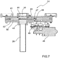
Entre la goulotte 10 de réception des pièces de monnaie et le tube intérieur fixe 26 du coulisseau d'admission de pièces s'étend (
Le clapet 43 comporte un alésage rectiligne 46 de réception d'un galet 47 monté en bout d'une manivelle 48 montée rotative sous l'action d'un moteur de clapet 49. Quand la manivelle 48 est entraînée en rotation par le moteur 49, son galet d'extrémité 47 se déplace dans l'alésage 46 en entraînant le clapet 43 en déplacement dans l'intervalle 50, soit pour obturer les orifices 44, 45 et donc interrompre la communication entre la goulotte 10 et le tube intérieur 26 du coulisseau en position fermée, soit pour dégager les orifices et autoriser la communication entre la goulotte et le tube intérieur du coulisseau, en position ouverte.The
On rappellera que la fonction du clapet de rétention 14 est indispensable car, lors du retour d'une cartouche pleine vers la zone de stockage, il faut attendre le temps de transport de la cartouche pleine dans un sens et le temps de transport d'une cartouche vide dans le sens inverse avant de pouvoir « jeter » à nouveau des pièces dans la cartouche vide correctement positionnée dans la borne de péage. Pendant ces deux temps, le clapet doit être en position fermée et les pièces stockées dans une zone tampon en amont et non représentée au dessin.It will be recalled that the function of the
Ici encore, on peut prévoir des fins de course de type Reed.Here again, it is possible to provide Reed-type limit switches.
La borne de péage 60 qui vient d'être décrite fait partie d'un système automatique 70 de transport pneumatique de cartouches cylindriques 1, de réception par gravité des pièces de monnaie, par une ligne de tubes cylindriques 71 reliant la borne 60, et d'autres, et au moins une station d'entrée / sortie de cartouches et un stockeur de recettes.The
De la ligne de tubes, on n'a représenté au dessin que le tube 15 qui se raccorde à la borne 60.From the line of tubes, the drawing shows only the
Claims (11)
- A toll terminal (60) of a pneumatic conveying system (70) of cylindrical cartridges (1) by line of cylindrical tubes (71) comprising:- a cartridge (1) intended to receive the means of payment,- means (10) for receiving means of payment susceptible to a free fall,- a cartridge (1) input / output port (11) intended to receive the means of payment by gravity,- means (12) for receiving a cartridge (1) and,- means (13) for providing connection between the means (10) for receiving the means of payment and the inside of a cartridge (1),- the input / output port (11) is arranged for the passage of a cartridge (1) in an horizontal axis (8) position and- the cartridge receiving means (12) are arranged to tilt the cartridge to a vertical axis (8) position,- the input / output port (11) is the orifice of the receiving means (12) through which a tube (15) of the line of cylindrical tubes (71) is connected to the receiving means (12) and thus to the terminal (60),- With said tube (15), an empty cartridge (1) is propelled into the terminal before being evacuated by said input / output port (11), once filled with means of payment.
- The toll terminal according to claim 1, wherein the cartridge receiving means (12) comprise a frame (20) rotatably mounted under the action of driving means (24).
- The toll terminal according to claim 2, wherein the rotation of the frame (20) is effected by means of a gear with cog-wheels (23,24).
- The toll terminal according to one of claim 1 to 3, wherein the cartridge (1) input / output port (11) is equipped with an air exhaust valve (17) intended to reduce the air flow and thus initiate the braking of the cartridge (1) on arrival in the terminal.
- The toll terminal according to one of claim 1 to 4, wherein the cartridge receiving means (12) are arranged to brake the cartridge.
- The toll terminal according to claim 5, wherein there is provided in the cartridge receiving means (12), means (17) for exhausting air to brake the cartridge (1).
- The toll terminal according to one of claim 5 and 6, wherein there is provided in the cartridge receiving means (12), a block (18), of a bi-component memory foam for braking the cartridge (1).
- The toll terminal according to one of claims 1 to 7, wherein there is provided in the means (10) for receiving means of payment, means (14) for retaining means of payment arranged to prevent the passage of these means of payment to the cartridge receiving means (12) and thus to inhibit the means (13) for providing connection between means (10) for receiving means of payment and for the inside of a cartridge (1) .
- The toll terminal according to one of claims 1 to 8, wherein said communication means (13) comprise a telescopic slide (25,26).
- The toll terminal according to one of claims 1 to 9, wherein there is provided, in said retaining means (14), a valve (43) slidably mounted between the means (10) for receiving the means of payment and said communication means (13).
- An automatic system (70) of pneumatic conveyance of cylindrical cartridges (1), for receiving coins by gravity, by a line (71) of cylindrical tubes connected to at least one toll terminal (60) according to one of the preceding claims and for receiving coins, and an input / output cartridge station, characterized in that the line of tubes (71) is connected to the toll terminal (60) by an horizontal axis (8) line segment (15) and the toll terminal (60) comprises means (12,20) arranged for tilting the cartridges (1) from an horizontal axis (8) position to a vertical axis (8) position.
Applications Claiming Priority (2)
| Application Number | Priority Date | Filing Date | Title |
|---|---|---|---|
| BE2014/0759A BE1022195B1 (en) | 2014-10-10 | 2014-10-10 | TEN TERMINAL AND AUTOMATIC PNEUMATIC CARTRIDGE TRANSPORT SYSTEM COMPRISING THE TERMINAL |
| PCT/EP2015/073273 WO2016055575A1 (en) | 2014-10-10 | 2015-10-08 | Payment terminal and automatic system for pneumatically transporting cartridges comprising the terminal |
Publications (2)
| Publication Number | Publication Date |
|---|---|
| EP3204923A1 EP3204923A1 (en) | 2017-08-16 |
| EP3204923B1 true EP3204923B1 (en) | 2019-09-18 |
Family
ID=52745851
Family Applications (1)
| Application Number | Title | Priority Date | Filing Date |
|---|---|---|---|
| EP15775241.1A Not-in-force EP3204923B1 (en) | 2014-10-10 | 2015-10-08 | Payment terminal and automatic system for pneumatically transporting cartridges comprising the terminal |
Country Status (4)
| Country | Link |
|---|---|
| EP (1) | EP3204923B1 (en) |
| BE (1) | BE1022195B1 (en) |
| ES (1) | ES2759994T3 (en) |
| WO (1) | WO2016055575A1 (en) |
Family Cites Families (4)
| Publication number | Priority date | Publication date | Assignee | Title |
|---|---|---|---|---|
| GB9204398D0 (en) * | 1992-02-29 | 1992-04-15 | Air Tube Conveyors | Conveyor |
| US5356243A (en) * | 1993-04-21 | 1994-10-18 | Mosler, Inc. | Pivoting tube section for pneumatic transport tube system |
| FR2837480B1 (en) * | 2002-03-20 | 2004-10-08 | Sncf | OBJECT RECEIVING AND TRANSFEROR FOR PNEUMATIC CONVEYING DEVICE |
| US7341406B1 (en) * | 2005-09-16 | 2008-03-11 | Diebold, Incorporated | Pneumatic transport tube system |
-
2014
- 2014-10-10 BE BE2014/0759A patent/BE1022195B1/en not_active IP Right Cessation
-
2015
- 2015-10-08 EP EP15775241.1A patent/EP3204923B1/en not_active Not-in-force
- 2015-10-08 ES ES15775241T patent/ES2759994T3/en active Active
- 2015-10-08 WO PCT/EP2015/073273 patent/WO2016055575A1/en active Application Filing
Non-Patent Citations (1)
| Title |
|---|
| None * |
Also Published As
| Publication number | Publication date |
|---|---|
| WO2016055575A1 (en) | 2016-04-14 |
| BE1022195B1 (en) | 2016-02-26 |
| ES2759994T3 (en) | 2020-05-12 |
| EP3204923A1 (en) | 2017-08-16 |
Similar Documents
| Publication | Publication Date | Title |
|---|---|---|
| CA2494436C (en) | Tilting surface | |
| EP1935813A1 (en) | Device for distributing stick-shaped objects one by one | |
| EP2705937B1 (en) | Wooden logs sawing machine | |
| EP0351295A1 (en) | Coin-handling device | |
| CA2404148A1 (en) | Automatic selective sorting device | |
| EP3204923B1 (en) | Payment terminal and automatic system for pneumatically transporting cartridges comprising the terminal | |
| EP0830654B1 (en) | Pneumatic conveyor for small metallic pieces, particularly coins, for payment points | |
| FR2805126A1 (en) | METHOD FOR FORMING A SPHERICAL BODY AND DEVICE THEREFOR | |
| EP0002979A1 (en) | Installation for the automatic and registered stocking and releasing of currency | |
| WO2013079852A1 (en) | Device for continuously moving gas cylinders towards a filling machine | |
| FR3010989A1 (en) | INSTALLATION FOR AUTOMATIC UNLOADING OF OBJECTS OF A CONTAINER | |
| FR2682750A1 (en) | AMMUNITION STORE, ESPECIALLY FOR CHAR. | |
| WO2013149968A1 (en) | Compact system for sterilization by bombardment of electrons | |
| FR2708488A1 (en) | Device for inserting objects into a postal sorting machine | |
| WO2001051392A1 (en) | Device for pneumatic transportation of cartridges | |
| EP2358616B1 (en) | Transfer station and method for a pneumatic cartridge | |
| FR3094349A1 (en) | Drone charging station | |
| EP2772457A1 (en) | Facility to assist with packaging items | |
| WO2001051391A1 (en) | Method and device for conveying objects in a suspended position | |
| FR2829477A1 (en) | Automatic device for continuous emptying of crates into hopper | |
| CH647299A5 (en) | Automatic dispenser, in particular for banks | |
| FR2669611A1 (en) | Installation for sorting components | |
| FR3086933A1 (en) | TRANSFER DEVICE FOR CONVEYOR | |
| FR2733202A1 (en) | Conveyor arrangement for stacked foodstuff products, e.g. sandwiches | |
| CH482610A (en) | Method and device for pneumatic transport of parts |
Legal Events
| Date | Code | Title | Description |
|---|---|---|---|
| STAA | Information on the status of an ep patent application or granted ep patent |
Free format text: STATUS: THE INTERNATIONAL PUBLICATION HAS BEEN MADE |
|
| PUAI | Public reference made under article 153(3) epc to a published international application that has entered the european phase |
Free format text: ORIGINAL CODE: 0009012 |
|
| STAA | Information on the status of an ep patent application or granted ep patent |
Free format text: STATUS: REQUEST FOR EXAMINATION WAS MADE |
|
| 17P | Request for examination filed |
Effective date: 20170309 |
|
| AK | Designated contracting states |
Kind code of ref document: A1 Designated state(s): AL AT BE BG CH CY CZ DE DK EE ES FI FR GB GR HR HU IE IS IT LI LT LU LV MC MK MT NL NO PL PT RO RS SE SI SK SM TR |
|
| AX | Request for extension of the european patent |
Extension state: BA ME |
|
| DAV | Request for validation of the european patent (deleted) | ||
| DAX | Request for extension of the european patent (deleted) | ||
| GRAP | Despatch of communication of intention to grant a patent |
Free format text: ORIGINAL CODE: EPIDOSNIGR1 |
|
| STAA | Information on the status of an ep patent application or granted ep patent |
Free format text: STATUS: GRANT OF PATENT IS INTENDED |
|
| INTG | Intention to grant announced |
Effective date: 20190416 |
|
| GRAS | Grant fee paid |
Free format text: ORIGINAL CODE: EPIDOSNIGR3 |
|
| GRAA | (expected) grant |
Free format text: ORIGINAL CODE: 0009210 |
|
| STAA | Information on the status of an ep patent application or granted ep patent |
Free format text: STATUS: THE PATENT HAS BEEN GRANTED |
|
| AK | Designated contracting states |
Kind code of ref document: B1 Designated state(s): AL AT BE BG CH CY CZ DE DK EE ES FI FR GB GR HR HU IE IS IT LI LT LU LV MC MK MT NL NO PL PT RO RS SE SI SK SM TR |
|
| REG | Reference to a national code |
Ref country code: GB Ref legal event code: FG4D Free format text: NOT ENGLISH |
|
| REG | Reference to a national code |
Ref country code: CH Ref legal event code: EP |
|
| REG | Reference to a national code |
Ref country code: DE Ref legal event code: R096 Ref document number: 602015038297 Country of ref document: DE |
|
| REG | Reference to a national code |
Ref country code: AT Ref legal event code: REF Ref document number: 1182218 Country of ref document: AT Kind code of ref document: T Effective date: 20191015 |
|
| REG | Reference to a national code |
Ref country code: IE Ref legal event code: FG4D Free format text: LANGUAGE OF EP DOCUMENT: FRENCH |
|
| REG | Reference to a national code |
Ref country code: NL Ref legal event code: FP |
|
| REG | Reference to a national code |
Ref country code: CH Ref legal event code: NV Representative=s name: NOVAGRAAF INTERNATIONAL SA, CH |
|
| PG25 | Lapsed in a contracting state [announced via postgrant information from national office to epo] |
Ref country code: FI Free format text: LAPSE BECAUSE OF FAILURE TO SUBMIT A TRANSLATION OF THE DESCRIPTION OR TO PAY THE FEE WITHIN THE PRESCRIBED TIME-LIMIT Effective date: 20190918 Ref country code: LT Free format text: LAPSE BECAUSE OF FAILURE TO SUBMIT A TRANSLATION OF THE DESCRIPTION OR TO PAY THE FEE WITHIN THE PRESCRIBED TIME-LIMIT Effective date: 20190918 Ref country code: BG Free format text: LAPSE BECAUSE OF FAILURE TO SUBMIT A TRANSLATION OF THE DESCRIPTION OR TO PAY THE FEE WITHIN THE PRESCRIBED TIME-LIMIT Effective date: 20191218 Ref country code: NO Free format text: LAPSE BECAUSE OF FAILURE TO SUBMIT A TRANSLATION OF THE DESCRIPTION OR TO PAY THE FEE WITHIN THE PRESCRIBED TIME-LIMIT Effective date: 20191218 Ref country code: HR Free format text: LAPSE BECAUSE OF FAILURE TO SUBMIT A TRANSLATION OF THE DESCRIPTION OR TO PAY THE FEE WITHIN THE PRESCRIBED TIME-LIMIT Effective date: 20190918 Ref country code: SE Free format text: LAPSE BECAUSE OF FAILURE TO SUBMIT A TRANSLATION OF THE DESCRIPTION OR TO PAY THE FEE WITHIN THE PRESCRIBED TIME-LIMIT Effective date: 20190918 |
|
| REG | Reference to a national code |
Ref country code: LT Ref legal event code: MG4D |
|
| PG25 | Lapsed in a contracting state [announced via postgrant information from national office to epo] |
Ref country code: RS Free format text: LAPSE BECAUSE OF FAILURE TO SUBMIT A TRANSLATION OF THE DESCRIPTION OR TO PAY THE FEE WITHIN THE PRESCRIBED TIME-LIMIT Effective date: 20190918 Ref country code: AL Free format text: LAPSE BECAUSE OF FAILURE TO SUBMIT A TRANSLATION OF THE DESCRIPTION OR TO PAY THE FEE WITHIN THE PRESCRIBED TIME-LIMIT Effective date: 20190918 Ref country code: GR Free format text: LAPSE BECAUSE OF FAILURE TO SUBMIT A TRANSLATION OF THE DESCRIPTION OR TO PAY THE FEE WITHIN THE PRESCRIBED TIME-LIMIT Effective date: 20191219 Ref country code: LV Free format text: LAPSE BECAUSE OF FAILURE TO SUBMIT A TRANSLATION OF THE DESCRIPTION OR TO PAY THE FEE WITHIN THE PRESCRIBED TIME-LIMIT Effective date: 20190918 |
|
| PG25 | Lapsed in a contracting state [announced via postgrant information from national office to epo] |
Ref country code: RO Free format text: LAPSE BECAUSE OF FAILURE TO SUBMIT A TRANSLATION OF THE DESCRIPTION OR TO PAY THE FEE WITHIN THE PRESCRIBED TIME-LIMIT Effective date: 20190918 Ref country code: PL Free format text: LAPSE BECAUSE OF FAILURE TO SUBMIT A TRANSLATION OF THE DESCRIPTION OR TO PAY THE FEE WITHIN THE PRESCRIBED TIME-LIMIT Effective date: 20190918 Ref country code: EE Free format text: LAPSE BECAUSE OF FAILURE TO SUBMIT A TRANSLATION OF THE DESCRIPTION OR TO PAY THE FEE WITHIN THE PRESCRIBED TIME-LIMIT Effective date: 20190918 Ref country code: PT Free format text: LAPSE BECAUSE OF FAILURE TO SUBMIT A TRANSLATION OF THE DESCRIPTION OR TO PAY THE FEE WITHIN THE PRESCRIBED TIME-LIMIT Effective date: 20200120 |
|
| REG | Reference to a national code |
Ref country code: ES Ref legal event code: FG2A Ref document number: 2759994 Country of ref document: ES Kind code of ref document: T3 Effective date: 20200512 |
|
| PG25 | Lapsed in a contracting state [announced via postgrant information from national office to epo] |
Ref country code: SK Free format text: LAPSE BECAUSE OF FAILURE TO SUBMIT A TRANSLATION OF THE DESCRIPTION OR TO PAY THE FEE WITHIN THE PRESCRIBED TIME-LIMIT Effective date: 20190918 Ref country code: CZ Free format text: LAPSE BECAUSE OF FAILURE TO SUBMIT A TRANSLATION OF THE DESCRIPTION OR TO PAY THE FEE WITHIN THE PRESCRIBED TIME-LIMIT Effective date: 20190918 Ref country code: IS Free format text: LAPSE BECAUSE OF FAILURE TO SUBMIT A TRANSLATION OF THE DESCRIPTION OR TO PAY THE FEE WITHIN THE PRESCRIBED TIME-LIMIT Effective date: 20200224 Ref country code: SM Free format text: LAPSE BECAUSE OF FAILURE TO SUBMIT A TRANSLATION OF THE DESCRIPTION OR TO PAY THE FEE WITHIN THE PRESCRIBED TIME-LIMIT Effective date: 20190918 |
|
| REG | Reference to a national code |
Ref country code: DE Ref legal event code: R097 Ref document number: 602015038297 Country of ref document: DE |
|
| PLBE | No opposition filed within time limit |
Free format text: ORIGINAL CODE: 0009261 |
|
| STAA | Information on the status of an ep patent application or granted ep patent |
Free format text: STATUS: NO OPPOSITION FILED WITHIN TIME LIMIT |
|
| PG2D | Information on lapse in contracting state deleted |
Ref country code: IS |
|
| PG25 | Lapsed in a contracting state [announced via postgrant information from national office to epo] |
Ref country code: LU Free format text: LAPSE BECAUSE OF NON-PAYMENT OF DUE FEES Effective date: 20191008 Ref country code: DK Free format text: LAPSE BECAUSE OF FAILURE TO SUBMIT A TRANSLATION OF THE DESCRIPTION OR TO PAY THE FEE WITHIN THE PRESCRIBED TIME-LIMIT Effective date: 20190918 Ref country code: IS Free format text: LAPSE BECAUSE OF FAILURE TO SUBMIT A TRANSLATION OF THE DESCRIPTION OR TO PAY THE FEE WITHIN THE PRESCRIBED TIME-LIMIT Effective date: 20200119 |
|
| 26N | No opposition filed |
Effective date: 20200619 |
|
| PG25 | Lapsed in a contracting state [announced via postgrant information from national office to epo] |
Ref country code: SI Free format text: LAPSE BECAUSE OF FAILURE TO SUBMIT A TRANSLATION OF THE DESCRIPTION OR TO PAY THE FEE WITHIN THE PRESCRIBED TIME-LIMIT Effective date: 20190918 Ref country code: MC Free format text: LAPSE BECAUSE OF FAILURE TO SUBMIT A TRANSLATION OF THE DESCRIPTION OR TO PAY THE FEE WITHIN THE PRESCRIBED TIME-LIMIT Effective date: 20190918 |
|
| PG25 | Lapsed in a contracting state [announced via postgrant information from national office to epo] |
Ref country code: IE Free format text: LAPSE BECAUSE OF NON-PAYMENT OF DUE FEES Effective date: 20191008 |
|
| PG25 | Lapsed in a contracting state [announced via postgrant information from national office to epo] |
Ref country code: CY Free format text: LAPSE BECAUSE OF FAILURE TO SUBMIT A TRANSLATION OF THE DESCRIPTION OR TO PAY THE FEE WITHIN THE PRESCRIBED TIME-LIMIT Effective date: 20190918 |
|
| PG25 | Lapsed in a contracting state [announced via postgrant information from national office to epo] |
Ref country code: MT Free format text: LAPSE BECAUSE OF FAILURE TO SUBMIT A TRANSLATION OF THE DESCRIPTION OR TO PAY THE FEE WITHIN THE PRESCRIBED TIME-LIMIT Effective date: 20190918 Ref country code: HU Free format text: LAPSE BECAUSE OF FAILURE TO SUBMIT A TRANSLATION OF THE DESCRIPTION OR TO PAY THE FEE WITHIN THE PRESCRIBED TIME-LIMIT; INVALID AB INITIO Effective date: 20151008 |
|
| PGFP | Annual fee paid to national office [announced via postgrant information from national office to epo] |
Ref country code: NL Payment date: 20211027 Year of fee payment: 7 |
|
| PGFP | Annual fee paid to national office [announced via postgrant information from national office to epo] |
Ref country code: AT Payment date: 20211006 Year of fee payment: 7 Ref country code: GB Payment date: 20211019 Year of fee payment: 7 Ref country code: ES Payment date: 20211115 Year of fee payment: 7 Ref country code: DE Payment date: 20211007 Year of fee payment: 7 |
|
| PGFP | Annual fee paid to national office [announced via postgrant information from national office to epo] |
Ref country code: IT Payment date: 20211008 Year of fee payment: 7 Ref country code: FR Payment date: 20211027 Year of fee payment: 7 Ref country code: CH Payment date: 20211013 Year of fee payment: 7 Ref country code: BE Payment date: 20211027 Year of fee payment: 7 |
|
| PG25 | Lapsed in a contracting state [announced via postgrant information from national office to epo] |
Ref country code: TR Free format text: LAPSE BECAUSE OF FAILURE TO SUBMIT A TRANSLATION OF THE DESCRIPTION OR TO PAY THE FEE WITHIN THE PRESCRIBED TIME-LIMIT Effective date: 20190918 |
|
| PG25 | Lapsed in a contracting state [announced via postgrant information from national office to epo] |
Ref country code: MK Free format text: LAPSE BECAUSE OF FAILURE TO SUBMIT A TRANSLATION OF THE DESCRIPTION OR TO PAY THE FEE WITHIN THE PRESCRIBED TIME-LIMIT Effective date: 20190918 |
|
| REG | Reference to a national code |
Ref country code: DE Ref legal event code: R119 Ref document number: 602015038297 Country of ref document: DE |
|
| REG | Reference to a national code |
Ref country code: CH Ref legal event code: PL |
|
| REG | Reference to a national code |
Ref country code: NL Ref legal event code: MM Effective date: 20221101 |
|
| P01 | Opt-out of the competence of the unified patent court (upc) registered |
Effective date: 20230428 |
|
| REG | Reference to a national code |
Ref country code: AT Ref legal event code: MM01 Ref document number: 1182218 Country of ref document: AT Kind code of ref document: T Effective date: 20221008 |
|
| REG | Reference to a national code |
Ref country code: BE Ref legal event code: MM Effective date: 20221031 |
|
| GBPC | Gb: european patent ceased through non-payment of renewal fee |
Effective date: 20221008 |
|
| PG25 | Lapsed in a contracting state [announced via postgrant information from national office to epo] |
Ref country code: NL Free format text: LAPSE BECAUSE OF NON-PAYMENT OF DUE FEES Effective date: 20221101 Ref country code: LI Free format text: LAPSE BECAUSE OF NON-PAYMENT OF DUE FEES Effective date: 20221031 Ref country code: FR Free format text: LAPSE BECAUSE OF NON-PAYMENT OF DUE FEES Effective date: 20221031 Ref country code: DE Free format text: LAPSE BECAUSE OF NON-PAYMENT OF DUE FEES Effective date: 20230503 Ref country code: CH Free format text: LAPSE BECAUSE OF NON-PAYMENT OF DUE FEES Effective date: 20221031 Ref country code: AT Free format text: LAPSE BECAUSE OF NON-PAYMENT OF DUE FEES Effective date: 20221008 |
|
| PG25 | Lapsed in a contracting state [announced via postgrant information from national office to epo] |
Ref country code: BE Free format text: LAPSE BECAUSE OF NON-PAYMENT OF DUE FEES Effective date: 20221031 |
|
| PG25 | Lapsed in a contracting state [announced via postgrant information from national office to epo] |
Ref country code: IT Free format text: LAPSE BECAUSE OF NON-PAYMENT OF DUE FEES Effective date: 20221008 Ref country code: GB Free format text: LAPSE BECAUSE OF NON-PAYMENT OF DUE FEES Effective date: 20221008 |
|
| REG | Reference to a national code |
Ref country code: ES Ref legal event code: FD2A Effective date: 20231127 |
|
| PG25 | Lapsed in a contracting state [announced via postgrant information from national office to epo] |
Ref country code: ES Free format text: LAPSE BECAUSE OF NON-PAYMENT OF DUE FEES Effective date: 20221009 |
|
| PG25 | Lapsed in a contracting state [announced via postgrant information from national office to epo] |
Ref country code: ES Free format text: LAPSE BECAUSE OF NON-PAYMENT OF DUE FEES Effective date: 20221009 |