EP3204730B1 - Optical position encoder - Google Patents
Optical position encoder Download PDFInfo
- Publication number
- EP3204730B1 EP3204730B1 EP15745333.3A EP15745333A EP3204730B1 EP 3204730 B1 EP3204730 B1 EP 3204730B1 EP 15745333 A EP15745333 A EP 15745333A EP 3204730 B1 EP3204730 B1 EP 3204730B1
- Authority
- EP
- European Patent Office
- Prior art keywords
- optical
- reimaged
- detector
- thermal imaging
- imaging detector
- Prior art date
- Legal status (The legal status is an assumption and is not a legal conclusion. Google has not performed a legal analysis and makes no representation as to the accuracy of the status listed.)
- Active
Links
Images

Classifications
-
- G—PHYSICS
- G01—MEASURING; TESTING
- G01D—MEASURING NOT SPECIALLY ADAPTED FOR A SPECIFIC VARIABLE; ARRANGEMENTS FOR MEASURING TWO OR MORE VARIABLES NOT COVERED IN A SINGLE OTHER SUBCLASS; TARIFF METERING APPARATUS; MEASURING OR TESTING NOT OTHERWISE PROVIDED FOR
- G01D5/00—Mechanical means for transferring the output of a sensing member; Means for converting the output of a sensing member to another variable where the form or nature of the sensing member does not constrain the means for converting; Transducers not specially adapted for a specific variable
- G01D5/26—Mechanical means for transferring the output of a sensing member; Means for converting the output of a sensing member to another variable where the form or nature of the sensing member does not constrain the means for converting; Transducers not specially adapted for a specific variable characterised by optical transfer means, i.e. using infrared, visible, or ultraviolet light
- G01D5/28—Mechanical means for transferring the output of a sensing member; Means for converting the output of a sensing member to another variable where the form or nature of the sensing member does not constrain the means for converting; Transducers not specially adapted for a specific variable characterised by optical transfer means, i.e. using infrared, visible, or ultraviolet light with deflection of beams of light, e.g. for direct optical indication
- G01D5/30—Mechanical means for transferring the output of a sensing member; Means for converting the output of a sensing member to another variable where the form or nature of the sensing member does not constrain the means for converting; Transducers not specially adapted for a specific variable characterised by optical transfer means, i.e. using infrared, visible, or ultraviolet light with deflection of beams of light, e.g. for direct optical indication the beams of light being detected by photocells
-
- G—PHYSICS
- G01—MEASURING; TESTING
- G01D—MEASURING NOT SPECIALLY ADAPTED FOR A SPECIFIC VARIABLE; ARRANGEMENTS FOR MEASURING TWO OR MORE VARIABLES NOT COVERED IN A SINGLE OTHER SUBCLASS; TARIFF METERING APPARATUS; MEASURING OR TESTING NOT OTHERWISE PROVIDED FOR
- G01D5/00—Mechanical means for transferring the output of a sensing member; Means for converting the output of a sensing member to another variable where the form or nature of the sensing member does not constrain the means for converting; Transducers not specially adapted for a specific variable
- G01D5/26—Mechanical means for transferring the output of a sensing member; Means for converting the output of a sensing member to another variable where the form or nature of the sensing member does not constrain the means for converting; Transducers not specially adapted for a specific variable characterised by optical transfer means, i.e. using infrared, visible, or ultraviolet light
- G01D5/32—Mechanical means for transferring the output of a sensing member; Means for converting the output of a sensing member to another variable where the form or nature of the sensing member does not constrain the means for converting; Transducers not specially adapted for a specific variable characterised by optical transfer means, i.e. using infrared, visible, or ultraviolet light with attenuation or whole or partial obturation of beams of light
- G01D5/34—Mechanical means for transferring the output of a sensing member; Means for converting the output of a sensing member to another variable where the form or nature of the sensing member does not constrain the means for converting; Transducers not specially adapted for a specific variable characterised by optical transfer means, i.e. using infrared, visible, or ultraviolet light with attenuation or whole or partial obturation of beams of light the beams of light being detected by photocells
- G01D5/341—Mechanical means for transferring the output of a sensing member; Means for converting the output of a sensing member to another variable where the form or nature of the sensing member does not constrain the means for converting; Transducers not specially adapted for a specific variable characterised by optical transfer means, i.e. using infrared, visible, or ultraviolet light with attenuation or whole or partial obturation of beams of light the beams of light being detected by photocells controlling the movement of a following part
-
- H—ELECTRICITY
- H04—ELECTRIC COMMUNICATION TECHNIQUE
- H04N—PICTORIAL COMMUNICATION, e.g. TELEVISION
- H04N23/00—Cameras or camera modules comprising electronic image sensors; Control thereof
- H04N23/20—Cameras or camera modules comprising electronic image sensors; Control thereof for generating image signals from infrared radiation only
- H04N23/23—Cameras or camera modules comprising electronic image sensors; Control thereof for generating image signals from infrared radiation only from thermal infrared radiation
Definitions
- EP 0 206 396 A1 describes an optical scanning unit which comprises a radiation source, an objective lens and a translational-position and angular-position detection system for determining the translational position and the angular position of the objective lens within the scanning unit.
- the system comprises a conical-ring mirror which is centered and fixed relative to the objective lens and a radiation-sensitive detection system which is arranged in the path of the radiation reflected from the mirror and which comprises two detectors which are spaced by an annular strip and are each divided into four quadrants.
- EP 2 511 669 A2 describes an encoder which includes a scale that includes a plurality of unit block patterns arranged in a position measuring direction with a period of a pitch.
- a pattern of the unit block pattern has a symmetrical shape with respect to a symmetry line perpendicular to the position measuring direction.
- Each unit block pattern includes a plurality of divided sections along a direction perpendicular to the position measuring direction.
- An area ratio of the pattern which is a value made by dividing an area of the pattern in each divided section by an area of the divided section is different between two adjacent divided sections.
- the pattern in each divided section has a rectangular shape defined by two parallel lines that extend in the position measuring direction and two parallel lines that extend in the direction perpendicular to the position measuring direction.
- EP 2 492 648 A2 describes an optical encoder which includes a light source, a scale which is irradiated by the light source and has a fine pitch pattern and a coarse pitch pattern in one track, a photo detector array which detects transmitting light or reflected light from the scale which are emitted from the light source, a signal processing means including first initial-stage amplifier means that generates a position detection signal from the photo detector array, and a control means that uses an output signal from the first initial-stage amplifier means to control a light amount variation of the light source.
- the optical encoder can operate in a high resolution detection mode that forms the photo detector array at a first pitch to detect the fine pitch pattern and a low resolution detection mode that forms the photo detector array at a second pitch to detect the coarse pitch pattern.
- US 4 270 048 A describes apparatus for receiving electromagnetic radiant energy, including a radiation detection element, a movable optical element for directing the radiation toward the detection element, and a drive system for automatically adjusting the position of the optical element to cause the radiation to always be directed toward the detection element.
- the drive system includes a pivotally mounted permanent magnet connected with the optical element, a plurality of coils arranged circumferentially about the magnet, and radiation-responsive control circuit for selectively energizing the coils to produce a magnetic field that displaces the magnet and the optical element to maintain direction of the radiation upon the radiation detection element.
- US 5 247 173 A describes a device for the acquisition of the angular position of mobile means of the type including a luminous source emitting an incident beam in a known direction and a reflecting surface attached to the mobile means.
- the device also includes an array of elementary charge coupled sensors positioned so as to be at least partly scanned by the reflected beam.
- the device includes in addition optical means for limiting the width of the incident beam.
- the said array is connected to an electronic circuit producing a digital signal varying according to the position and/or the number of elementary sensors illuminated by the reflected beam.
- aspects and embodiments are directed to position sensing techniques in which an optical system's own detector is used to encode the position of a component within the optical system. As discussed in more detail below, in infrared optical systems, this encoder may be entirely passive.
- a reimaged optical imaging system includes a thermal imaging detector, an optical component, and at least one reflector located on the optical component, wherein the at least one reflector is configured to reimage the thermal imaging detector onto itself, and wherein a position of at the reimaged reflection on the thermal imaging detector encodes a position of the optical component relative to the thermal imaging detector.
- the optical component may be located approximately at an intermediate image plane of the reimaged optical imaging system.
- the optical component is a movable component configured to be selectively moved into and out of an optical path between the intermediate image plane and the imaging detector.
- the optical component is a filter.
- the thermal imaging detector may be a microbolometer or solid-state photovoltaic detector array, for example.
- the reimaged optical imaging system may further include a cold chamber, wherein the thermal imaging detector is located within the cold chamber.
- the reflector may include any of a V-groove, a corner cube, a spherical reflector, an aspheric reflector, or an alignment mask, for example.
- a thermal reimaged optical imaging system includes a cold chamber, a thermal imaging detector disposed within the cold chamber, a first optical sub-system configured to receive and focus infrared electromagnetic radiation from a scene onto an intermediate image plane, a second optical sub-system configured to reimage the infrared electromagnetic radiation from the intermediate image plane onto the thermal imaging detector, a movable optical component configured to be movable into an out of an optical path of the thermal imaging detector, the movable optical component being located approximately at the intermediate image plane when in the optical path, and a reflector located on the movable optical component and configured to reimage the thermal imaging detector onto itself to thereby encode a position of the optical component relative to the thermal imaging detector.
- the cold chamber is configured to cool or temperature-stabilize the thermal imaging detector.
- the reflector may include any of a V-groove, a corner cube, a spherical reflector, an aspheric reflector, or an alignment mask, for example.
- Another embodiment is directed to a method of determining a position of an optical component in a reimaged optical imaging system.
- the method may include receiving and focusing electromagnetic radiation from a scene onto an intermediate image plane, reimaging the electromagnetic radiation from the intermediate image plane onto a thermal imaging detector configured to produce an image of the scene from the electromagnetic radiation, moving an optical component into an optical path of the thermal imaging detector and proximate the intermediate image plane, the optical component having a reflector attached thereto, and reimaging a reflection of the thermal imaging detector, reflected by the reflector, onto the thermal imaging detector, wherein a position of the reimaged reflection on the thermal imaging detector encodes the position of the optical component relative to the thermal imaging detector.
- a component such as a filter
- a shutter mechanism In these systems, it may be desirable or necessary to accurately know the position of the component when it is moved into the optical path, specifically, its alignment relative to the optical axis or some other reference point.
- Aspects and embodiments are directed to mechanisms for determining the position (or alignment) of a component in an optical system relative to the system detector using the detector itself and without requiring a mechanical position encoder or angle resolver.
- certain embodiments use one or more light sources attached to the component whose position is to be determined that are reimaged onto the system detector, and thus encode the position of the component.
- the light sources may include one or more emitters (such as an LED), or in an aspect that is according to the invention, the light sources may include one or more reflectors that are configured to reimage the detector onto itself. The position of the image(s) of the light source(s) on the detector encodes the position of the component.
- FIG. 1 there is illustrated a schematic block diagram of one example of a reimaged optical system 100.
- the system includes a first optical sub-system 110 that receives electromagnetic radiation 115 from a scene and focuses the electromagnetic radiation onto an intermediate image plane (represented by the intersection of the two illustrated rays of the electromagnetic radiation 115).
- a second optical sub-system 120 relays and focuses the electromagnetic radiation 115 from the intermediate image plane onto an imaging detector 130.
- Dotted line 140 represents the optical axis of the system 100, perpendicular (or normal) to the detector 130.
- each of the first and second optical sub-systems 110 and 120 may include one or more lenses and/or mirrors, or other optical components, configured to direct and focus the electromagnetic radiation 115.
- the detector 130 in an aspect not according to the invention, may be any type of optical detector, such as a focal plane array (FPA) or visible imaging detector, for example, or in an aspect according to the invention, the detector is a thermal imaging detector.
- FPA focal plane array
- the system 100 further includes a component 150 whose position is to be determined.
- the component 150 is located approximately at the intermediate image plane of the system 100.
- a light source 160 is located on the component 150 and directs electromagnetic radiation 165 to the detector 130.
- the position of the light source 160 on the component 150 may be accurately established (for example, during manufacture or system set-up), such that the position of the image of the light source on the detector 130 may be used to accurately determine the position or alignment of the component 150 relative to the detector 130.
- the component 150 may be any type of component used in an optical system, such as a bandpass filter, polarizer, or other component.
- the detector 130 may not "see” the component 150, but instead images the electromagnetic radiation 115 from the scene as received through the component 150.
- Location of one or more light sources 160 on the component 150 may obscure objects in the scene being imaged by the detector; however, in many applications small obstructions in the image caused by the light source(s) 160 are tolerable and may not significantly degrade the imaging performance of the optical system 100.
- the light source 160 includes an emitter, such as a light emitting diode (LED).
- the detector 130 may be a visible waveband sensor, and the light source 160 may be an LED emitting at a selected wavelength or wavelengths in the visible spectrum.
- the light source 160 is a reflector, such as a lens, mirror, or other reflective element, that reimages an emitter on the detector 130 back to the detector.
- the detector 130 itself may be the emitter.
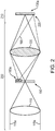
- the detector 130a is a thermal imaging detector (such as an Indium Antimonide array) that is housed within a cold chamber, such as an Integrated Dewar Assembly (IDA), for example.
- IDA Integrated Dewar Assembly
- the optical system includes a "warm" (typically ambient) sub-system 200 that generally includes the majority of the optical elements in the system, and which is not cooled, and a cold sub-system 210 that includes the thermal imaging detector 130a and any other components located within the cold chamber.
- Infrared electromagnetic radiation 115a from a scene is focused onto the thermal imaging detector 130a via the intermediate image plane by the first and second optical sub-systems 110, 120.
- a reflective feature 160a is located on the component 150 and reimages the cold detector 130a back onto itself.
- the detector 130a "sees" a cold image of itself, indicated at reference 220, retro-reflected from the reflector 160a.
- the optical system is imaging a scene at ambient temperatures (e.g., 250 or 300 Kelvin, average), and therefore the image of the cold detector 130a (which may be cooled to approximately 70-80 Kelvin) may be easily distinguished in the image obtained at the detector.
- the position encoding mechanism is entirely passive.
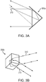
- the reflector may have any of numerous forms, provided that it is configured to retro-reflect an image of the detector 130 (or of another emitter attached to or collocated with the detector) back to the detector.
- the reflector 300a may include a V-groove that retro-reflects electromagnetic radiation 310 incident thereon.
- the V-groove reflector 300a reflects the incident electromagnetic radiation 310 back at the angle of incidence in two dimensions.
- the reflector 300b may include a retro-reflecting corner cube, as shown in FIG. 3B .
- the corner cube reflector 300b reflects the incident electromagnetic radiation 310 back at the angle of incidence in three dimensions.
- the reflector may include a spherical or aspheric reflector or an alignment mask. In each example, the reflector images the cold detector 130a back onto itself, creating a contrast in the thermal background.
- the component 150 is located at or near the intermediate image plane of the optical system.
- This arrangement may provide the easiest implementation of the optical position encoding mechanisms discussed herein, as the light source 160 may be directly reimaged onto the detector 130.
- the position of components that are not at intermediate images may be encoded onto the detector 130 by using a reflector (such as a lens or mirror) placed at the intermediate image to reflect light from an emitter on the component 150 whose position is to be encoded.
- a single light source 160 (not according to the invention, an emitter, or according to the invention, a reflector) may be sufficient to act as a position encoder for the associated component, as discussed above.
- more accurate position information may be obtained by using two or more light sources 160, each configured to direct or retro-reflect light onto the detector 130.
- the light source(s) 160 may be attached directly to the optical component 150.
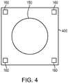
- the light source(s) 160 may be attached to the platform. For example, referring to FIG.
- FIG. 4 there is illustrated a block diagram of one example of a movable platform 400 upon which is mounted the optical component 150 (e.g., a filter), with four light sources 160 positioned at the four corners of the platform. In other examples, any number of light sources 160 may be placed at various fixed locations on the platform 400 relative to the optical component 150.
- the optical component 150 e.g., a filter
- aspects and embodiments provide an optical position encoder that can be easily incorporated with the component whose position is to be determined, and which leverages the existing system detector to obtain the position measurements.
- embodiments of the optical position encoder include one or more light sources associated with the component whose position is to be determined that are reimaged onto the detector, such that the position of the images of the sources on the detector encode the position of the associated component.
- the position encoder may be entirely passive.
Landscapes
- Physics & Mathematics (AREA)
- General Physics & Mathematics (AREA)
- Engineering & Computer Science (AREA)
- Multimedia (AREA)
- Signal Processing (AREA)
- Health & Medical Sciences (AREA)
- Toxicology (AREA)
- Length Measuring Devices By Optical Means (AREA)
- Radiation Pyrometers (AREA)
- Optical Transform (AREA)
Applications Claiming Priority (2)
| Application Number | Priority Date | Filing Date | Title |
|---|---|---|---|
| US14/510,180 US9726524B2 (en) | 2014-10-09 | 2014-10-09 | Optical position encoder |
| PCT/US2015/041221 WO2016057100A1 (en) | 2014-10-09 | 2015-07-21 | Optical position encoder |
Publications (2)
| Publication Number | Publication Date |
|---|---|
| EP3204730A1 EP3204730A1 (en) | 2017-08-16 |
| EP3204730B1 true EP3204730B1 (en) | 2019-06-12 |
Family
ID=53773554
Family Applications (1)
| Application Number | Title | Priority Date | Filing Date |
|---|---|---|---|
| EP15745333.3A Active EP3204730B1 (en) | 2014-10-09 | 2015-07-21 | Optical position encoder |
Country Status (3)
| Country | Link |
|---|---|
| US (1) | US9726524B2 (da) |
| EP (1) | EP3204730B1 (da) |
| WO (1) | WO2016057100A1 (da) |
Families Citing this family (3)
| Publication number | Priority date | Publication date | Assignee | Title |
|---|---|---|---|---|
| FR3071328B1 (fr) * | 2017-09-18 | 2019-09-13 | Thales | Imageur infrarouge |
| US10436640B2 (en) * | 2017-10-17 | 2019-10-08 | Raytheon Company | Alignment assembly and method for multi-spectral optical systems |
| EP4343280A1 (en) * | 2022-09-20 | 2024-03-27 | Hexagon Technology Center GmbH | Monitoring arrangement for an optical system |
Family Cites Families (8)
| Publication number | Priority date | Publication date | Assignee | Title |
|---|---|---|---|---|
| DE2910588C2 (de) | 1979-03-17 | 1982-04-29 | Deutsche Forschungs- und Versuchsanstalt für Luft- und Raumfahrt e.V., 5300 Bonn | Vorrichtung zum Empfang einer elektromagnetischen Strahlung |
| NL8501665A (nl) | 1985-06-10 | 1987-01-02 | Philips Nv | Optische aftasteenheid met positie- en standdetektiestelsel voor een elektromagnetisch gelagerd objektief. |
| FR2676822B1 (fr) | 1991-05-24 | 1993-11-05 | Thomson Trt Defense | Dispositif d'acquisition de la position angulaire instantanee d'un moyen mobile et systemes opto-mecaniques integrant un tel dispositif. |
| JP3631551B2 (ja) | 1996-01-23 | 2005-03-23 | 株式会社ミツトヨ | 光学式エンコーダ |
| JP4280447B2 (ja) | 2001-02-20 | 2009-06-17 | キヤノン株式会社 | 反射スケールおよびそれを用いた変位検出装置 |
| JP5765968B2 (ja) | 2011-02-28 | 2015-08-19 | キヤノン株式会社 | 光学式エンコーダ |
| JP6032924B2 (ja) | 2011-04-13 | 2016-11-30 | キヤノン株式会社 | エンコーダ |
| US8842216B2 (en) | 2012-08-30 | 2014-09-23 | Raytheon Company | Movable pixelated filter array |
-
2014
- 2014-10-09 US US14/510,180 patent/US9726524B2/en active Active
-
2015
- 2015-07-21 EP EP15745333.3A patent/EP3204730B1/en active Active
- 2015-07-21 WO PCT/US2015/041221 patent/WO2016057100A1/en not_active Ceased
Non-Patent Citations (1)
| Title |
|---|
| None * |
Also Published As
| Publication number | Publication date |
|---|---|
| WO2016057100A1 (en) | 2016-04-14 |
| US20160103000A1 (en) | 2016-04-14 |
| EP3204730A1 (en) | 2017-08-16 |
| US9726524B2 (en) | 2017-08-08 |
Similar Documents
| Publication | Publication Date | Title |
|---|---|---|
| JP7622128B2 (ja) | 回転コンパクト光測距システム | |
| JP7084705B2 (ja) | 測量装置 | |
| TWI803546B (zh) | 旋轉緊密光測距系統 | |
| JP3976021B2 (ja) | 位置計測システム | |
| CN111954796A (zh) | 电磁波检测装置以及信息获取系统 | |
| KR102052757B1 (ko) | 이미징 시스템용 광학 모니터링 디바이스 | |
| US10466044B2 (en) | Sensor imager and laser alignment system | |
| EP3640677B1 (en) | Tracker of a surveying apparatus for tracking a target | |
| US11172108B2 (en) | Imaging device | |
| US9726524B2 (en) | Optical position encoder | |
| US7355178B2 (en) | Infrared thermometer with through-the-lens visible targeting system | |
| CN112629680B (zh) | 基于夏克-哈特曼波前传感的航空相机检焦装置及方法 | |
| US10908383B1 (en) | Local control loop for projection system focus adjustment | |
| US11933722B2 (en) | Micro mirror arrays for measuring electromagnetic radiation | |
| RU2622239C1 (ru) | Устройство для бесконтактного измерения температуры объекта | |
| US11555982B1 (en) | Detecting positional deviations in an optical module | |
| Langeveld | A Method to Measure the Flatness of the LSST Focal Plane Assembly in Situ |
Legal Events
| Date | Code | Title | Description |
|---|---|---|---|
| STAA | Information on the status of an ep patent application or granted ep patent |
Free format text: STATUS: THE INTERNATIONAL PUBLICATION HAS BEEN MADE |
|
| PUAI | Public reference made under article 153(3) epc to a published international application that has entered the european phase |
Free format text: ORIGINAL CODE: 0009012 |
|
| STAA | Information on the status of an ep patent application or granted ep patent |
Free format text: STATUS: REQUEST FOR EXAMINATION WAS MADE |
|
| 17P | Request for examination filed |
Effective date: 20170403 |
|
| AK | Designated contracting states |
Kind code of ref document: A1 Designated state(s): AL AT BE BG CH CY CZ DE DK EE ES FI FR GB GR HR HU IE IS IT LI LT LU LV MC MK MT NL NO PL PT RO RS SE SI SK SM TR |
|
| AX | Request for extension of the european patent |
Extension state: BA ME |
|
| DAV | Request for validation of the european patent (deleted) | ||
| DAX | Request for extension of the european patent (deleted) | ||
| REG | Reference to a national code |
Ref country code: DE Ref legal event code: R079 Ref document number: 602015031838 Country of ref document: DE Free format text: PREVIOUS MAIN CLASS: G01D0005340000 Ipc: G01D0005300000 |
|
| STAA | Information on the status of an ep patent application or granted ep patent |
Free format text: STATUS: EXAMINATION IS IN PROGRESS |
|
| RIC1 | Information provided on ipc code assigned before grant |
Ipc: G01D 5/30 20060101AFI20180126BHEP Ipc: H04N 5/33 20060101ALI20180126BHEP Ipc: G01D 5/34 20060101ALI20180126BHEP |
|
| 17Q | First examination report despatched |
Effective date: 20180208 |
|
| GRAP | Despatch of communication of intention to grant a patent |
Free format text: ORIGINAL CODE: EPIDOSNIGR1 |
|
| STAA | Information on the status of an ep patent application or granted ep patent |
Free format text: STATUS: GRANT OF PATENT IS INTENDED |
|
| INTG | Intention to grant announced |
Effective date: 20190103 |
|
| GRAS | Grant fee paid |
Free format text: ORIGINAL CODE: EPIDOSNIGR3 |
|
| GRAA | (expected) grant |
Free format text: ORIGINAL CODE: 0009210 |
|
| STAA | Information on the status of an ep patent application or granted ep patent |
Free format text: STATUS: THE PATENT HAS BEEN GRANTED |
|
| AK | Designated contracting states |
Kind code of ref document: B1 Designated state(s): AL AT BE BG CH CY CZ DE DK EE ES FI FR GB GR HR HU IE IS IT LI LT LU LV MC MK MT NL NO PL PT RO RS SE SI SK SM TR |
|
| REG | Reference to a national code |
Ref country code: GB Ref legal event code: FG4D |
|
| REG | Reference to a national code |
Ref country code: CH Ref legal event code: EP |
|
| REG | Reference to a national code |
Ref country code: AT Ref legal event code: REF Ref document number: 1143151 Country of ref document: AT Kind code of ref document: T Effective date: 20190615 |
|
| REG | Reference to a national code |
Ref country code: DE Ref legal event code: R096 Ref document number: 602015031838 Country of ref document: DE |
|
| REG | Reference to a national code |
Ref country code: IE Ref legal event code: FG4D |
|
| REG | Reference to a national code |
Ref country code: NL Ref legal event code: MP Effective date: 20190612 |
|
| REG | Reference to a national code |
Ref country code: LT Ref legal event code: MG4D |
|
| PG25 | Lapsed in a contracting state [announced via postgrant information from national office to epo] |
Ref country code: HR Free format text: LAPSE BECAUSE OF FAILURE TO SUBMIT A TRANSLATION OF THE DESCRIPTION OR TO PAY THE FEE WITHIN THE PRESCRIBED TIME-LIMIT Effective date: 20190612 Ref country code: LT Free format text: LAPSE BECAUSE OF FAILURE TO SUBMIT A TRANSLATION OF THE DESCRIPTION OR TO PAY THE FEE WITHIN THE PRESCRIBED TIME-LIMIT Effective date: 20190612 Ref country code: NO Free format text: LAPSE BECAUSE OF FAILURE TO SUBMIT A TRANSLATION OF THE DESCRIPTION OR TO PAY THE FEE WITHIN THE PRESCRIBED TIME-LIMIT Effective date: 20190912 Ref country code: FI Free format text: LAPSE BECAUSE OF FAILURE TO SUBMIT A TRANSLATION OF THE DESCRIPTION OR TO PAY THE FEE WITHIN THE PRESCRIBED TIME-LIMIT Effective date: 20190612 Ref country code: AL Free format text: LAPSE BECAUSE OF FAILURE TO SUBMIT A TRANSLATION OF THE DESCRIPTION OR TO PAY THE FEE WITHIN THE PRESCRIBED TIME-LIMIT Effective date: 20190612 Ref country code: SE Free format text: LAPSE BECAUSE OF FAILURE TO SUBMIT A TRANSLATION OF THE DESCRIPTION OR TO PAY THE FEE WITHIN THE PRESCRIBED TIME-LIMIT Effective date: 20190612 |
|
| PG25 | Lapsed in a contracting state [announced via postgrant information from national office to epo] |
Ref country code: LV Free format text: LAPSE BECAUSE OF FAILURE TO SUBMIT A TRANSLATION OF THE DESCRIPTION OR TO PAY THE FEE WITHIN THE PRESCRIBED TIME-LIMIT Effective date: 20190612 Ref country code: BG Free format text: LAPSE BECAUSE OF FAILURE TO SUBMIT A TRANSLATION OF THE DESCRIPTION OR TO PAY THE FEE WITHIN THE PRESCRIBED TIME-LIMIT Effective date: 20190912 Ref country code: GR Free format text: LAPSE BECAUSE OF FAILURE TO SUBMIT A TRANSLATION OF THE DESCRIPTION OR TO PAY THE FEE WITHIN THE PRESCRIBED TIME-LIMIT Effective date: 20190913 Ref country code: RS Free format text: LAPSE BECAUSE OF FAILURE TO SUBMIT A TRANSLATION OF THE DESCRIPTION OR TO PAY THE FEE WITHIN THE PRESCRIBED TIME-LIMIT Effective date: 20190612 |
|
| REG | Reference to a national code |
Ref country code: AT Ref legal event code: MK05 Ref document number: 1143151 Country of ref document: AT Kind code of ref document: T Effective date: 20190612 |
|
| PG25 | Lapsed in a contracting state [announced via postgrant information from national office to epo] |
Ref country code: PT Free format text: LAPSE BECAUSE OF FAILURE TO SUBMIT A TRANSLATION OF THE DESCRIPTION OR TO PAY THE FEE WITHIN THE PRESCRIBED TIME-LIMIT Effective date: 20191014 Ref country code: RO Free format text: LAPSE BECAUSE OF FAILURE TO SUBMIT A TRANSLATION OF THE DESCRIPTION OR TO PAY THE FEE WITHIN THE PRESCRIBED TIME-LIMIT Effective date: 20190612 Ref country code: NL Free format text: LAPSE BECAUSE OF FAILURE TO SUBMIT A TRANSLATION OF THE DESCRIPTION OR TO PAY THE FEE WITHIN THE PRESCRIBED TIME-LIMIT Effective date: 20190612 Ref country code: CZ Free format text: LAPSE BECAUSE OF FAILURE TO SUBMIT A TRANSLATION OF THE DESCRIPTION OR TO PAY THE FEE WITHIN THE PRESCRIBED TIME-LIMIT Effective date: 20190612 Ref country code: EE Free format text: LAPSE BECAUSE OF FAILURE TO SUBMIT A TRANSLATION OF THE DESCRIPTION OR TO PAY THE FEE WITHIN THE PRESCRIBED TIME-LIMIT Effective date: 20190612 Ref country code: AT Free format text: LAPSE BECAUSE OF FAILURE TO SUBMIT A TRANSLATION OF THE DESCRIPTION OR TO PAY THE FEE WITHIN THE PRESCRIBED TIME-LIMIT Effective date: 20190612 Ref country code: SK Free format text: LAPSE BECAUSE OF FAILURE TO SUBMIT A TRANSLATION OF THE DESCRIPTION OR TO PAY THE FEE WITHIN THE PRESCRIBED TIME-LIMIT Effective date: 20190612 |
|
| PG25 | Lapsed in a contracting state [announced via postgrant information from national office to epo] |
Ref country code: IT Free format text: LAPSE BECAUSE OF FAILURE TO SUBMIT A TRANSLATION OF THE DESCRIPTION OR TO PAY THE FEE WITHIN THE PRESCRIBED TIME-LIMIT Effective date: 20190612 Ref country code: ES Free format text: LAPSE BECAUSE OF FAILURE TO SUBMIT A TRANSLATION OF THE DESCRIPTION OR TO PAY THE FEE WITHIN THE PRESCRIBED TIME-LIMIT Effective date: 20190612 Ref country code: IS Free format text: LAPSE BECAUSE OF FAILURE TO SUBMIT A TRANSLATION OF THE DESCRIPTION OR TO PAY THE FEE WITHIN THE PRESCRIBED TIME-LIMIT Effective date: 20191012 Ref country code: SM Free format text: LAPSE BECAUSE OF FAILURE TO SUBMIT A TRANSLATION OF THE DESCRIPTION OR TO PAY THE FEE WITHIN THE PRESCRIBED TIME-LIMIT Effective date: 20190612 |
|
| REG | Reference to a national code |
Ref country code: CH Ref legal event code: PL |
|
| REG | Reference to a national code |
Ref country code: DE Ref legal event code: R097 Ref document number: 602015031838 Country of ref document: DE |
|
| PG25 | Lapsed in a contracting state [announced via postgrant information from national office to epo] |
Ref country code: MC Free format text: LAPSE BECAUSE OF FAILURE TO SUBMIT A TRANSLATION OF THE DESCRIPTION OR TO PAY THE FEE WITHIN THE PRESCRIBED TIME-LIMIT Effective date: 20190612 Ref country code: TR Free format text: LAPSE BECAUSE OF FAILURE TO SUBMIT A TRANSLATION OF THE DESCRIPTION OR TO PAY THE FEE WITHIN THE PRESCRIBED TIME-LIMIT Effective date: 20190612 |
|
| REG | Reference to a national code |
Ref country code: BE Ref legal event code: MM Effective date: 20190731 |
|
| PLBE | No opposition filed within time limit |
Free format text: ORIGINAL CODE: 0009261 |
|
| STAA | Information on the status of an ep patent application or granted ep patent |
Free format text: STATUS: NO OPPOSITION FILED WITHIN TIME LIMIT |
|
| PG25 | Lapsed in a contracting state [announced via postgrant information from national office to epo] |
Ref country code: DK Free format text: LAPSE BECAUSE OF FAILURE TO SUBMIT A TRANSLATION OF THE DESCRIPTION OR TO PAY THE FEE WITHIN THE PRESCRIBED TIME-LIMIT Effective date: 20190612 Ref country code: PL Free format text: LAPSE BECAUSE OF FAILURE TO SUBMIT A TRANSLATION OF THE DESCRIPTION OR TO PAY THE FEE WITHIN THE PRESCRIBED TIME-LIMIT Effective date: 20190612 |
|
| 26N | No opposition filed |
Effective date: 20200313 |
|
| PG25 | Lapsed in a contracting state [announced via postgrant information from national office to epo] |
Ref country code: SI Free format text: LAPSE BECAUSE OF FAILURE TO SUBMIT A TRANSLATION OF THE DESCRIPTION OR TO PAY THE FEE WITHIN THE PRESCRIBED TIME-LIMIT Effective date: 20190612 Ref country code: IS Free format text: LAPSE BECAUSE OF FAILURE TO SUBMIT A TRANSLATION OF THE DESCRIPTION OR TO PAY THE FEE WITHIN THE PRESCRIBED TIME-LIMIT Effective date: 20200224 Ref country code: BE Free format text: LAPSE BECAUSE OF NON-PAYMENT OF DUE FEES Effective date: 20190731 Ref country code: CH Free format text: LAPSE BECAUSE OF NON-PAYMENT OF DUE FEES Effective date: 20190731 Ref country code: LU Free format text: LAPSE BECAUSE OF NON-PAYMENT OF DUE FEES Effective date: 20190721 Ref country code: LI Free format text: LAPSE BECAUSE OF NON-PAYMENT OF DUE FEES Effective date: 20190731 |
|
| PG2D | Information on lapse in contracting state deleted |
Ref country code: IS |
|
| PG25 | Lapsed in a contracting state [announced via postgrant information from national office to epo] |
Ref country code: IE Free format text: LAPSE BECAUSE OF NON-PAYMENT OF DUE FEES Effective date: 20190721 |
|
| PG25 | Lapsed in a contracting state [announced via postgrant information from national office to epo] |
Ref country code: CY Free format text: LAPSE BECAUSE OF FAILURE TO SUBMIT A TRANSLATION OF THE DESCRIPTION OR TO PAY THE FEE WITHIN THE PRESCRIBED TIME-LIMIT Effective date: 20190612 |
|
| PG25 | Lapsed in a contracting state [announced via postgrant information from national office to epo] |
Ref country code: MT Free format text: LAPSE BECAUSE OF FAILURE TO SUBMIT A TRANSLATION OF THE DESCRIPTION OR TO PAY THE FEE WITHIN THE PRESCRIBED TIME-LIMIT Effective date: 20190612 Ref country code: HU Free format text: LAPSE BECAUSE OF FAILURE TO SUBMIT A TRANSLATION OF THE DESCRIPTION OR TO PAY THE FEE WITHIN THE PRESCRIBED TIME-LIMIT; INVALID AB INITIO Effective date: 20150721 |
|
| PG25 | Lapsed in a contracting state [announced via postgrant information from national office to epo] |
Ref country code: MK Free format text: LAPSE BECAUSE OF FAILURE TO SUBMIT A TRANSLATION OF THE DESCRIPTION OR TO PAY THE FEE WITHIN THE PRESCRIBED TIME-LIMIT Effective date: 20190612 |
|
| P01 | Opt-out of the competence of the unified patent court (upc) registered |
Effective date: 20230530 |
|
| PGFP | Annual fee paid to national office [announced via postgrant information from national office to epo] |
Ref country code: DE Payment date: 20250620 Year of fee payment: 11 |
|
| PGFP | Annual fee paid to national office [announced via postgrant information from national office to epo] |
Ref country code: GB Payment date: 20260618 Year of fee payment: 12 |
|
| PGFP | Annual fee paid to national office [announced via postgrant information from national office to epo] |
Ref country code: FR Payment date: 20260618 Year of fee payment: 12 |