EP3204666B1 - Mechanische dichtung mit hydropad-flächenprofil - Google Patents
Mechanische dichtung mit hydropad-flächenprofil Download PDFInfo
- Publication number
- EP3204666B1 EP3204666B1 EP15782182.8A EP15782182A EP3204666B1 EP 3204666 B1 EP3204666 B1 EP 3204666B1 EP 15782182 A EP15782182 A EP 15782182A EP 3204666 B1 EP3204666 B1 EP 3204666B1
- Authority
- EP
- European Patent Office
- Prior art keywords
- face
- hydro
- seal
- radial
- rotary end
- Prior art date
- Legal status (The legal status is an assumption and is not a legal conclusion. Google has not performed a legal analysis and makes no representation as to the accuracy of the status listed.)
- Active
Links
- 239000012530 fluid Substances 0.000 claims description 24
- 230000002093 peripheral effect Effects 0.000 claims description 24
- 238000000034 method Methods 0.000 claims description 18
- 230000013011 mating Effects 0.000 claims description 17
- 239000007788 liquid Substances 0.000 claims description 9
- 238000007789 sealing Methods 0.000 claims description 9
- 239000000498 cooling water Substances 0.000 claims description 3
- 230000003993 interaction Effects 0.000 claims description 2
- 238000005086 pumping Methods 0.000 description 6
- 238000005461 lubrication Methods 0.000 description 5
- XLYOFNOQVPJJNP-UHFFFAOYSA-N water Substances O XLYOFNOQVPJJNP-UHFFFAOYSA-N 0.000 description 5
- 210000004907 gland Anatomy 0.000 description 3
- 230000035515 penetration Effects 0.000 description 2
- OTMSDBZUPAUEDD-UHFFFAOYSA-N Ethane Chemical compound CC OTMSDBZUPAUEDD-UHFFFAOYSA-N 0.000 description 1
- -1 LNG) Chemical class 0.000 description 1
- 238000001816 cooling Methods 0.000 description 1
- 229930195733 hydrocarbon Natural products 0.000 description 1
- 150000002430 hydrocarbons Chemical class 0.000 description 1
- 238000009434 installation Methods 0.000 description 1
- 239000000314 lubricant Substances 0.000 description 1
- 239000000203 mixture Substances 0.000 description 1
- 230000004048 modification Effects 0.000 description 1
- 238000012986 modification Methods 0.000 description 1
- 230000000737 periodic effect Effects 0.000 description 1
- 230000001737 promoting effect Effects 0.000 description 1
- 230000000717 retained effect Effects 0.000 description 1
- 238000011144 upstream manufacturing Methods 0.000 description 1
Images
Classifications
-
- F—MECHANICAL ENGINEERING; LIGHTING; HEATING; WEAPONS; BLASTING
- F16—ENGINEERING ELEMENTS AND UNITS; GENERAL MEASURES FOR PRODUCING AND MAINTAINING EFFECTIVE FUNCTIONING OF MACHINES OR INSTALLATIONS; THERMAL INSULATION IN GENERAL
- F16J—PISTONS; CYLINDERS; SEALINGS
- F16J15/00—Sealings
- F16J15/16—Sealings between relatively-moving surfaces
- F16J15/34—Sealings between relatively-moving surfaces with slip-ring pressed against a more or less radial face on one member
- F16J15/3404—Sealings between relatively-moving surfaces with slip-ring pressed against a more or less radial face on one member and characterised by parts or details relating to lubrication, cooling or venting of the seal
- F16J15/3408—Sealings between relatively-moving surfaces with slip-ring pressed against a more or less radial face on one member and characterised by parts or details relating to lubrication, cooling or venting of the seal at least one ring having an uneven slipping surface
- F16J15/3412—Sealings between relatively-moving surfaces with slip-ring pressed against a more or less radial face on one member and characterised by parts or details relating to lubrication, cooling or venting of the seal at least one ring having an uneven slipping surface with cavities
- F16J15/342—Sealings between relatively-moving surfaces with slip-ring pressed against a more or less radial face on one member and characterised by parts or details relating to lubrication, cooling or venting of the seal at least one ring having an uneven slipping surface with cavities with means for feeding fluid directly to the face
-
- F—MECHANICAL ENGINEERING; LIGHTING; HEATING; WEAPONS; BLASTING
- F16—ENGINEERING ELEMENTS AND UNITS; GENERAL MEASURES FOR PRODUCING AND MAINTAINING EFFECTIVE FUNCTIONING OF MACHINES OR INSTALLATIONS; THERMAL INSULATION IN GENERAL
- F16J—PISTONS; CYLINDERS; SEALINGS
- F16J15/00—Sealings
- F16J15/16—Sealings between relatively-moving surfaces
- F16J15/34—Sealings between relatively-moving surfaces with slip-ring pressed against a more or less radial face on one member
- F16J15/3436—Pressing means
- F16J15/3452—Pressing means the pressing force resulting from the action of a spring
-
- F—MECHANICAL ENGINEERING; LIGHTING; HEATING; WEAPONS; BLASTING
- F16—ENGINEERING ELEMENTS AND UNITS; GENERAL MEASURES FOR PRODUCING AND MAINTAINING EFFECTIVE FUNCTIONING OF MACHINES OR INSTALLATIONS; THERMAL INSULATION IN GENERAL
- F16J—PISTONS; CYLINDERS; SEALINGS
- F16J15/00—Sealings
- F16J15/16—Sealings between relatively-moving surfaces
- F16J15/34—Sealings between relatively-moving surfaces with slip-ring pressed against a more or less radial face on one member
- F16J15/3404—Sealings between relatively-moving surfaces with slip-ring pressed against a more or less radial face on one member and characterised by parts or details relating to lubrication, cooling or venting of the seal
- F16J15/3408—Sealings between relatively-moving surfaces with slip-ring pressed against a more or less radial face on one member and characterised by parts or details relating to lubrication, cooling or venting of the seal at least one ring having an uneven slipping surface
- F16J15/3412—Sealings between relatively-moving surfaces with slip-ring pressed against a more or less radial face on one member and characterised by parts or details relating to lubrication, cooling or venting of the seal at least one ring having an uneven slipping surface with cavities
-
- F—MECHANICAL ENGINEERING; LIGHTING; HEATING; WEAPONS; BLASTING
- F16—ENGINEERING ELEMENTS AND UNITS; GENERAL MEASURES FOR PRODUCING AND MAINTAINING EFFECTIVE FUNCTIONING OF MACHINES OR INSTALLATIONS; THERMAL INSULATION IN GENERAL
- F16J—PISTONS; CYLINDERS; SEALINGS
- F16J15/00—Sealings
- F16J15/16—Sealings between relatively-moving surfaces
- F16J15/34—Sealings between relatively-moving surfaces with slip-ring pressed against a more or less radial face on one member
- F16J15/3464—Mounting of the seal
Definitions
- This disclosure relates to rotary mechanical end face seals for liquid. More particularly, it relates to such seals that include a hydro-pad profile on one seal face to augment penetration of sealed fluid between relatively rotating sealing faces.
- Rotary mechanical end face seals find wide application in pumps for pumping a liquid process fluid.
- hydro-pad relieved areas, or depressions on one of the relatively rotating seal faces is a configuration to enhance flow of process fluid between the relatively rotating sealing faces to provide a liquid film for lubrication.
- hydro-pad reliefs or depressions take the form of arcuate (scalloped) areas positioned at periodic intervals open at the peripheral edge of a seal face exposed to operating pressure of the process fluid.
- relieved areas have been formed to a depth of approximately 1.0 mm from the sealing face of the annular seal ring.
- U.S. Patent No. 5,368,314 also discloses a rotary end face seal assembly.
- the arrangement disclosed here provides a seal for a boiler feed pump that does not require external cooling. It is configured to operate without any separate cooling water delivery system. It is an uncooled seal.
- a rotary end face seal assembly to seal a fluid under pressure includes a pair of annular mating ring seal faces with one of the faces defining a sealing interface between radially inner and radially outer peripheral edges.
- a plurality of hydro-pad recesses are formed radially inwardly from the peripheral edge of one of the seal faces at the pressure side of the seal assembly at peripherally spaced intervals and a plurality of feeder grooves are formed radially inwardly from the same peripheral edge of the seal face between at least some hydro-pad recesses.
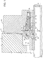
- FIG. 1 an inventive seal arrangement is illustrated in a single rotary mechanical end face seal assembly with process or high pressure at the outer edge of the seal faces and ambient or low pressure at the inner edge of the seal faces.
- the seal arrangement is intended to seal a fluid, in this case, a liquid, namely water at high temperature and pressure.
- the seal arrangement is intended to seal a fluid within a chamber 12 defined by a housing 14 and attached gland plate 15.
- a shaft 16 extends through the housing 14. Because the shaft 16 is intended to rotate relative to the housing 14, a seal must be provided to prevent or inhibit leakage of the fluid from the chamber 12.
- the seal assembly includes a seal ring configuration comprising a mating ring 18 rotationally fixed relative to a sleeve 20 by a pin 22.
- the sleeve 20 is mounted on the shaft 16 and rotates with the shaft.
- the mating ring 18 includes an annular mating ring seal face 24.
- An 0-ring 26 seals the mating ring 18 to the sleeve 20 so that no leakage occurs through this connection.
- the seal ring assembly also includes an axially movable primary ring 28 retained within a gland adaptor assembly 30.
- the primary ring 28 includes an annular primary ring seal face 32, illustrated in greater detail in Fig. 2 .
- the seal assembly defines with the pump housing 14 and gland plate 15 a high pressure zone P 2 , known as the process zone, in the chamber 12 upstream of the seal faces 24 and 32.
- a low pressure zone P 1 exists down-stream of the seal faces 24 and 32. This arrangement is sometimes referred to as an O.D. pressurized seal assembly.
- the primary ring 28 is axially biased by a biasing mechanism, such as a spring 34.
- a disk 33 is situated axially between the spring 34 and the primary ring 28.
- the spring 34 biases the primary ring 28 toward the mating ring 18, urging the primary ring seal face 32 into face-to-face sealing relation with the mating ring seal face 24.
- the primary ring seal face 32 engages the mating ring seal face 24 along a sealing interface, which inhibits the escape of process fluid from the high pressure zone P 2 to the low pressure zone P 1 . Because, in the illustrated embodiment, the annular mating ring seal face 24 is wider, in the radial direction, than the annular primary ring seal face 32, the interface is coextensive with the radial extent of the annular primary ring seal face 32. It must be understood however, that the interface could be defined by the mating ring seal face operating against a primary ring seal face of greater radial width.
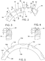
- the annular seal face 32 of primary ring 28 is illustrated in detail in Figs. 2-4 .
- the annular primary ring seal face 32 is defined by a radially outer edge or periphery 36 and a radially inner edge or periphery 38, thus illustrative of an O.D. pressurized seal.
- the sealing interface is coextensive with the annular seal face 32 between the outer and inner peripheral edges 36 and 38. In this embodiment the outer perimeter or edge 36 is exposed to the high pressure process fluid within the pump.
- the primary ring seal face 32 and therefore the seal interface defines a pumping mechanism in the form of plurality of spaced grooves or reliefs 44 disposed at spaced intervals about the peripheral edge 36 of primary seal ring seal face 32. They take the form of segments of a circle and are generally known in the art as hydro-pad recesses.
- This pumping mechanism is formed on the annular surface of the primary ring seal face 32 extending from the pressure side of the seal, the outer peripheral edge 36 toward the low pressure side, the inner peripheral edge 38.
- Each hydro-pad recess 44 is a crescent-shaped relief open at the outer peripheral edge 36 of seal face 32. It has a radially inner terminus defined by a circular edge 46.
- the radial extent or "length" of the hydro-pad recess on seal face 32 is the distance from the outer edge 36 of seal face 32 to the radial innermost extent of the recess 44 (l 1 in Fig. 3 ). It is determined by the length of radius "r 1 " of the circle defining the edge 46 minus the radial distance "d" between the centroid from which it is drawn to the outer peripheral edge 36 of the annular primary ring seal face 32. (See Fig. 2 )
- each hydro-pad recess 44 as illustrated in this embodiment, relative to the seal face 32 is preferably 1.0 mm (0.04 in.).
- the hydro-pad reliefs 44 serve to create a hydrodynamic force of process fluid between the primary ring seal face 32 and the mating ring seal face 24 when the seal is in operation.
- the reliefs 44 draw process fluid into the interface.
- the created hydrodynamic force causes the seal faces 24 and 32 to separate slightly and reduces the friction between the primary ring 28 and the mating ring 18. Presence of process fluid between the faces creates a liquid film which reduces friction. It also provides for reduced temperature and thermal distortion.
- the seal face 32 of the primary ring 28 also includes a series of radial slots or feeder grooves 60 disposed intermediate each adjacent pair of hydro-pads recesses 44.
- Each feeder groove 60 is open at the outer peripheral edge 36 of the seal ring face 32 and recessed from the annular face 32 of the primary ring 28 an axial depth of about 1.0 mm (0.04 in.).
- each groove 60 terminates at semi-circular terminus wall 64.
- the radial extent or length "l 2 " of each feeder groove 60 is somewhat longer than the radial extent or length discussed above, of each hydro-pad recess 44 (as seen in Fig. 4 ). It is expected that such length could be about 110 to 200 percent (%) of the radial extent of the hydro-pad recess 46. (See Figs. 3 and 4 ).
- each feeder groove includes side walls 62 parallel to a radial line midway between adjacent hydro-pad recesses 44, i.e., alternating hydro-pad recesses and feeder grooves.
- the width of each feeder groove 60 between walls 62 is approximately 5 mm (0.2 in.). However, it is within the scope of the disclosure to vary this relationship. That is, the number of feeder grooves 60 may differ from the number of hydro-pad recesses 44.
- a seal ring seal face 132 defines a pumping mechanism in the form of a plurality of equally spaced grooves or reliefs 144 shaped as a segment of a circle, generally known as hydro-pad recesses.
- This pumping mechanism is formed on the annular surface of seal ring face 132 along the radially outer peripheral edge 136 exposed to the high pressure process fluid.
- Hydro-pad recesses are sized and shaped as described in connection with the embodiment of Figs. 1-4 and function similarly.
- the seal ring 128 illustrated in Fig. 5 includes a radial feeder slot or feeder groove 160 disposed between pairs of adjacent hydro-pad recesses 144. That is, radial slots or feeder grooves 160 are disposed circumferentially about the peripheral edge 136 of seal face 132 between adjacent pairs of hydro-pad recesses 144, i.e., two hydro-pad recesses, one feeder groove, two hydro-pad recesses. These feeder grooves are sized and shaped as described in connection with the embodiment of Figs. 1-4 . They function similarly to the feeder grooves 60 of the earlier embodiment.
- Figs. 1-4 and 5 Illustrated herein in Figs. 1-4 and 5 are seal arrangements in accordance with the disclosure. They are exemplary of the principles discussed and not limiting in any way. The principles are applicable to other seal applications, sizes and operating conditions.
- a seal assembly as shown in Figs. 1-4 of the drawings is considered suitable for a pump having a rotatable shaft, 150 mm (6 in.) in diameter.
- the exemplary pump intended for pumping boiler feed water, may operate at a temperature of 200° C (390° F) at a pressure of 30 bar (450 psi).
- the pump shaft may operate at speeds between 1500 to 6000 rpm.
- the diameter of the outer peripheral edge 36 of the annular primary ring seal face 32 which is the high pressure seals of the seal interface, may be 190 mm (7.5 in.).
- the diameter of the inner peripheral edge 38 of the annular primary ring seal face 32 may be 165 mm (6.5 in.).
- the radial extent of the seal face 32 between peripheral edge 36 and peripheral edge 38 may be 12 mm (0.5 in.).
- the seal face 32 of the exemplary primary ring 28 has sixteen (16) equally spaced hydro-pad recesses 44 spaced about the annular primary ring seal face 32.
- Each has a circular edge 46 formed by a circle radius of 10 mm (0.4 inch) drawn from a center point 200 mm (8 inches) radially outward from the outer peripheral edge 36 a distance of 6 mm (0.25 in.).
- the radial extent l 1 (seen in Fig. 3 ) of each hydro-pad recess 44 from the outer peripheral edge 36 to its radially innermost point on circular edge 46 is 3 mm (0.125 in.).
- Each has a depth from the face surface of annular primary ring seal face 32 of 1 mm (0.04 in.).
- Each feeder groove 60 is disposed midway between each adjacent pair of hydro-pad recesses 44.
- Each feeder groove has a length l 2 (see Fig. 4 ) of 6 mm (0.25 in.) and depth from the surface of annular primary ring seal face 32 of 1 mm (0.04 in.).
- Each has a circumferential width of 5 mm (0.2 in.) between walls 62 with a radial inward end defined by a semi circular terminus wall formed by a radius r 2 of 2.5 mm (0.1 in.).
Claims (12)
- Rotierbare Endflächendichtungsgruppe, die zur Abdichtung eines nahe seines Verdampfungspunkts betriebenen Prozessfluids ohne gesondertes Wasserzufuhrsystem konfiguriert ist, wobei die rotierbare Endflächendichtungsgruppe umfasst:einen Passring (18) mit einer ringförmigen Passringdichtungsfläche (24);einen axial beweglichen Primärring (28) mit einer ringförmigen Primärringdichtungsfläche (32);und ein Vorspannelement (34), das den Primärring (28) zum Passring (18) vorspannt, wobei die Passringdichtungsfläche (24) und die Primärringdichtungsfläche (32) in einer gegenüberliegenden Dichtungsbeziehung angeordnet sind und eine Dichtungsschnittfläche zwischen einem radial äußeren Peripherierand (36) und einem radial inneren Peripherierand (38) der Primärringdichtungsfläche (32) definieren;dadurch gekennzeichnet, dass die Primärringdichtungsfläche (32) eine Vielzahl von Hydropad-Aussparungen (44) und eine Vielzahl radialer Zufuhrrillen (60) definiert, wobei sich die Vielzahl von Hydropad-Aussparungen (44) an periphär beabstandaten Intervallen vom radial äußeren Peripherierand (36) radial nach innen erstreckt, und sich die Vielzahl von radialen Zufuhrrillen (60) vom selben radial äußeren Peripherierand (36) zwischen mindestens einige der Hydropad-Aussparungen (44) radial nach innen erstreckt, wobei die kombinierte Interaktion der Vielzahl von Hydropad-Aussparungen (44) und der Vielzahl radialer Zufuhrrillen (60) ausreichend Prozessfluid zwischen die Passringdichtungsfläche (24) und die Primärringdichtungsfläche (32) zieht, um sicherzustellen, dass das Prozessfluid in der Dichtungsschnittfläche - das bei Druck- und Temperaturbedingungen nahe seines Verdampfungspunkts betrieben wird - im flüssigen Zustand bleibt.
- Rotierbare Endflächendichtungsgruppe nach Anspruch 1, wobei sich die Zufuhrrillen (60) in einem radialen Abstand, der größer als das radial innere Ausmaß der Hydropad-Aussparungen (44) ist radial nach innen erstrecken.
- Rotierbare Endflächendichtungsgruppe nach Anspruch 2, wobei das radial innere Ausmaß der Zufuhrrillen (60) 110 bis 200 Prozess des radial inneren Ausmaßes der Hydropad-Aussparungen (44) ist.
- Rotierbare Endflächendichtungsgruppe nach Anspruch 1, wobei jede der Hydropad-Aussparungen (44) einen radial inneren Endpunkt enthält.
- Rotierbare Endflächendichtungsgruppe nach Anspruch 4, wobei der radial innere Endpunkt jeder Vielzahl von Hydropad-Aussparungen (44) durch einen kreisförmigen Rand definiert wird.
- Rotierbare Endflächendichtungsgruppe nach Anspruch 5, wobei jede der Vielzahl von Zufuhrrillen (60) ein Paar paralleler Seitenwände enthält und an einer halbkreisförmigen Endpunktwand endet.
- Rotierbare Endflächendichtungsgruppe nach Anspruch 6, wobei das Paar Seitenwände parallel zu einer radialen Linie in der Mitte zwischen jedem Paar angrenzender Hydropadaussparungen (44) ist.
- Rotierbare Endflächendichtungsgruppe nach Anspruch 1, wobei jede der Hydropad-Aussparungen (44) eine axiale Tiefe von etwa 1,0 mm in die Dichtungsfläche aufweist.
- Rotierbare Endflächendichtungsgruppe nach Anspruch 8, wobei jede der Vielzahl von Zufuhrrillen (60) eine axiale Tiefe von etwa 1,0 mm in die Primärringdichtungsfläche (32) aufweist.
- Rotierbare Endflächendichtungsgruppe nach Anspruch 1, wobei die Vielzahl der Hydropad-Aussparungen (44) um die Peripherie der Primärringdichtungsfläche (32) gleichmäßig beabstandet sind.
- Rotierbare Endflächendichtungsgruppe nach Anspruch 1, wobei jede der Vielzahl der Zufuhrrillen (60) zwischen angrenzenden Paaren der Hydropad-Aussparungen (44) angeordnet ist.
- Rotierbare Endflächendichtungsanordnung nach Anspruch 1, wobei jede der Hydropad-Aussparungen (44) ein halbmondförmiges Relief ist, das am äußeren Peripherierand der Primärringdichtungsfläche (32) offen ist, und jede der Hydropad-Aussparungen (44) einen radial inneren Endpunkt aufweist, der durch einen kreisförmigen Rand definiert ist.
Applications Claiming Priority (2)
| Application Number | Priority Date | Filing Date | Title |
|---|---|---|---|
| US201462060139P | 2014-10-06 | 2014-10-06 | |
| PCT/US2015/054002 WO2016057394A1 (en) | 2014-10-06 | 2015-10-05 | Mechanical seal with hydro-pad face profile |
Publications (2)
| Publication Number | Publication Date |
|---|---|
| EP3204666A1 EP3204666A1 (de) | 2017-08-16 |
| EP3204666B1 true EP3204666B1 (de) | 2019-04-10 |
Family
ID=54337412
Family Applications (1)
| Application Number | Title | Priority Date | Filing Date |
|---|---|---|---|
| EP15782182.8A Active EP3204666B1 (de) | 2014-10-06 | 2015-10-05 | Mechanische dichtung mit hydropad-flächenprofil |
Country Status (4)
| Country | Link |
|---|---|
| US (1) | US10753476B2 (de) |
| EP (1) | EP3204666B1 (de) |
| JP (1) | JP6773649B2 (de) |
| WO (1) | WO2016057394A1 (de) |
Families Citing this family (6)
| Publication number | Priority date | Publication date | Assignee | Title |
|---|---|---|---|---|
| JP6798776B2 (ja) * | 2015-10-16 | 2020-12-09 | 株式会社リケン | シールリング |
| US11473680B2 (en) | 2016-07-12 | 2022-10-18 | John Crane Inc. | Non-collapsible flexible sealing membrane and seal assembly for rotary shaft equipment |
| ES2934247T3 (es) | 2016-07-12 | 2023-02-20 | Crane John Inc | Membrana de estanqueidad flexible no plegable y conjunto de estanqueidad para equipo de árbol giratorio |
| US11739844B2 (en) * | 2016-09-14 | 2023-08-29 | Eagle Industry Co., Ltd. | Mechanical seal |
| US11125334B2 (en) * | 2016-12-21 | 2021-09-21 | Eaton Intelligent Power Limited | Hydrodynamic sealing component and assembly |
| US11549589B2 (en) | 2018-02-21 | 2023-01-10 | Eagle Industry Co., Ltd. | Mechanical seal |
Family Cites Families (30)
| Publication number | Priority date | Publication date | Assignee | Title |
|---|---|---|---|---|
| US3383116A (en) * | 1964-09-30 | 1968-05-14 | J C Carter Company | Face seal |
| FR1599308A (de) * | 1968-06-08 | 1970-07-15 | ||
| US3588979A (en) | 1969-08-28 | 1971-06-29 | Gen Tire & Rubber Co | Bushing assembly machine and method |
| US3694894A (en) | 1970-01-14 | 1972-10-03 | Parker Hannifin Corp | Method of inserting a seal in a face-cut groove |
| US3695789A (en) * | 1970-04-13 | 1972-10-03 | Case Co J I | Balancing mechanism for fluid translating device |
| US3824660A (en) | 1973-05-04 | 1974-07-23 | Gen Tire & Rubber Co | Method and apparatus for vacuum assembling of bushings |
| US4407512A (en) | 1976-01-02 | 1983-10-04 | John Crane-Houdaille, Inc. | High pressure rotary mechanical seal |
| US4209884A (en) | 1979-01-02 | 1980-07-01 | Acf Industries, Incorporated | Method of forming valve seats |
| US4314704A (en) | 1980-03-10 | 1982-02-09 | Crane Packing Limited | Rotary mechanical face seals |
| DE3428744A1 (de) | 1983-08-12 | 1985-02-28 | Dickow-Pumpen KG, 8264 Waldkraiburg | Befestigung von ringfoermigen siliziumcarbid-bauteilen an metalltraegerteilen |
| US5368314A (en) * | 1986-10-28 | 1994-11-29 | Pacific Wietz Gmbh & Co. Kg | Contactless pressurizing-gas shaft seal |
| CH677266A5 (de) * | 1986-10-28 | 1991-04-30 | Pacific Wietz Gmbh & Co Kg | |
| JPH06105105B2 (ja) * | 1989-03-03 | 1994-12-21 | 日本ピラー工業株式会社 | 端面非接触形メカニカルシール |
| GB2232728B (en) | 1989-06-06 | 1992-12-09 | Crane John Uk Ltd | Mechanical face seals |
| JPH0743037B2 (ja) * | 1990-06-23 | 1995-05-15 | 吉秀 阿部 | 非接触メカニカルシール |
| JPH0756345B2 (ja) | 1990-07-09 | 1995-06-14 | 株式会社荏原製作所 | 非接触端面シール |
| DE4209484A1 (de) | 1991-06-12 | 1993-10-21 | Heinz Konrad Prof Dr I Mueller | Gleitringdichtung mit Rückförderwirkung |
| US5722665A (en) * | 1992-02-26 | 1998-03-03 | Durametallic Corporation | Spiral groove face seal |
| GB2296052A (en) | 1994-12-16 | 1996-06-19 | Crane John Uk Ltd | Mechanical face seals |
| US5938206A (en) * | 1996-11-01 | 1999-08-17 | John Crane Inc. | Pressure responsive primary ring for a non-contacting mechanical end face seal |
| US6454268B1 (en) * | 2001-02-09 | 2002-09-24 | Eagle Industry Co., Ltd. | Shaft seal device |
| GB2375148A (en) * | 2001-04-30 | 2002-11-06 | Corac Group Plc | A dry gas seal |
| DE10134086C2 (de) | 2001-07-13 | 2003-05-15 | Daimler Chrysler Ag | Verfahren und Vorrichtung zum Verbinden zweier Bauteile |
| GB0214515D0 (en) | 2002-06-24 | 2002-08-07 | Crane John Uk Ltd | Seals |
| US7377518B2 (en) | 2004-05-28 | 2008-05-27 | John Crane Inc. | Mechanical seal ring assembly with hydrodynamic pumping mechanism |
| DE102012214276A1 (de) * | 2012-08-10 | 2014-02-13 | Siemens Aktiengesellschaft | Wellendichtungsanordnung |
| JP6121446B2 (ja) | 2012-12-25 | 2017-04-26 | イーグル工業株式会社 | 摺動部品 |
| US9951873B2 (en) * | 2013-01-16 | 2018-04-24 | Eagle Industry Co., Ltd. | Sliding component |
| WO2014116800A1 (en) * | 2013-01-23 | 2014-07-31 | Flowserve Management Company | Mechanical face seal with a reverse trapezoidal face pattern |
| US9353865B2 (en) * | 2014-06-03 | 2016-05-31 | Thermo King Corporation | Mechanical face seal |
-
2015
- 2015-10-05 EP EP15782182.8A patent/EP3204666B1/de active Active
- 2015-10-05 JP JP2017518346A patent/JP6773649B2/ja active Active
- 2015-10-05 WO PCT/US2015/054002 patent/WO2016057394A1/en active Application Filing
- 2015-10-05 US US14/875,098 patent/US10753476B2/en active Active
Non-Patent Citations (1)
| Title |
|---|
| None * |
Also Published As
| Publication number | Publication date |
|---|---|
| EP3204666A1 (de) | 2017-08-16 |
| WO2016057394A1 (en) | 2016-04-14 |
| US10753476B2 (en) | 2020-08-25 |
| US20160097456A1 (en) | 2016-04-07 |
| JP2017530318A (ja) | 2017-10-12 |
| JP6773649B2 (ja) | 2020-10-21 |
Similar Documents
| Publication | Publication Date | Title |
|---|---|---|
| EP3204666B1 (de) | Mechanische dichtung mit hydropad-flächenprofil | |
| EP3575643B1 (de) | Gleitkomponente | |
| JP6616932B2 (ja) | 摺動部品 | |
| US10274086B2 (en) | Sliding component | |
| US7377518B2 (en) | Mechanical seal ring assembly with hydrodynamic pumping mechanism | |
| US10443737B2 (en) | Slide component | |
| US9927033B2 (en) | Split circumferential lift-off seal segment | |
| US6325381B1 (en) | High-pressure rotary seal | |
| RU2649733C2 (ru) | Выходное уплотнение редуктора | |
| WO2018088350A1 (ja) | しゅう動部品 | |
| JP2017530318A5 (de) | ||
| EP3087297B1 (de) | Elektrische korrosionsbeständige mechanische dichtung | |
| US10337616B2 (en) | Mechanical seal assembly | |
| US10344867B2 (en) | Sliding component | |
| US20170082203A1 (en) | Vented lift off seal assemblies | |
| US20210148470A1 (en) | Hydraulic seal |
Legal Events
| Date | Code | Title | Description |
|---|---|---|---|
| STAA | Information on the status of an ep patent application or granted ep patent |
Free format text: STATUS: THE INTERNATIONAL PUBLICATION HAS BEEN MADE |
|
| PUAI | Public reference made under article 153(3) epc to a published international application that has entered the european phase |
Free format text: ORIGINAL CODE: 0009012 |
|
| STAA | Information on the status of an ep patent application or granted ep patent |
Free format text: STATUS: REQUEST FOR EXAMINATION WAS MADE |
|
| 17P | Request for examination filed |
Effective date: 20170428 |
|
| AK | Designated contracting states |
Kind code of ref document: A1 Designated state(s): AL AT BE BG CH CY CZ DE DK EE ES FI FR GB GR HR HU IE IS IT LI LT LU LV MC MK MT NL NO PL PT RO RS SE SI SK SM TR |
|
| AX | Request for extension of the european patent |
Extension state: BA ME |
|
| DAV | Request for validation of the european patent (deleted) | ||
| DAX | Request for extension of the european patent (deleted) | ||
| STAA | Information on the status of an ep patent application or granted ep patent |
Free format text: STATUS: EXAMINATION IS IN PROGRESS |
|
| 17Q | First examination report despatched |
Effective date: 20180420 |
|
| GRAP | Despatch of communication of intention to grant a patent |
Free format text: ORIGINAL CODE: EPIDOSNIGR1 |
|
| STAA | Information on the status of an ep patent application or granted ep patent |
Free format text: STATUS: GRANT OF PATENT IS INTENDED |
|
| INTG | Intention to grant announced |
Effective date: 20181129 |
|
| GRAS | Grant fee paid |
Free format text: ORIGINAL CODE: EPIDOSNIGR3 |
|
| GRAA | (expected) grant |
Free format text: ORIGINAL CODE: 0009210 |
|
| STAA | Information on the status of an ep patent application or granted ep patent |
Free format text: STATUS: THE PATENT HAS BEEN GRANTED |
|
| AK | Designated contracting states |
Kind code of ref document: B1 Designated state(s): AL AT BE BG CH CY CZ DE DK EE ES FI FR GB GR HR HU IE IS IT LI LT LU LV MC MK MT NL NO PL PT RO RS SE SI SK SM TR |
|
| REG | Reference to a national code |
Ref country code: GB Ref legal event code: FG4D |
|
| REG | Reference to a national code |
Ref country code: CH Ref legal event code: EP Ref country code: AT Ref legal event code: REF Ref document number: 1119119 Country of ref document: AT Kind code of ref document: T Effective date: 20190415 |
|
| REG | Reference to a national code |
Ref country code: IE Ref legal event code: FG4D |
|
| REG | Reference to a national code |
Ref country code: DE Ref legal event code: R096 Ref document number: 602015028134 Country of ref document: DE |
|
| REG | Reference to a national code |
Ref country code: NL Ref legal event code: MP Effective date: 20190410 |
|
| REG | Reference to a national code |
Ref country code: LT Ref legal event code: MG4D |
|
| REG | Reference to a national code |
Ref country code: AT Ref legal event code: MK05 Ref document number: 1119119 Country of ref document: AT Kind code of ref document: T Effective date: 20190410 |
|
| PG25 | Lapsed in a contracting state [announced via postgrant information from national office to epo] |
Ref country code: NL Free format text: LAPSE BECAUSE OF FAILURE TO SUBMIT A TRANSLATION OF THE DESCRIPTION OR TO PAY THE FEE WITHIN THE PRESCRIBED TIME-LIMIT Effective date: 20190410 |
|
| PG25 | Lapsed in a contracting state [announced via postgrant information from national office to epo] |
Ref country code: SE Free format text: LAPSE BECAUSE OF FAILURE TO SUBMIT A TRANSLATION OF THE DESCRIPTION OR TO PAY THE FEE WITHIN THE PRESCRIBED TIME-LIMIT Effective date: 20190410 Ref country code: HR Free format text: LAPSE BECAUSE OF FAILURE TO SUBMIT A TRANSLATION OF THE DESCRIPTION OR TO PAY THE FEE WITHIN THE PRESCRIBED TIME-LIMIT Effective date: 20190410 Ref country code: LT Free format text: LAPSE BECAUSE OF FAILURE TO SUBMIT A TRANSLATION OF THE DESCRIPTION OR TO PAY THE FEE WITHIN THE PRESCRIBED TIME-LIMIT Effective date: 20190410 Ref country code: ES Free format text: LAPSE BECAUSE OF FAILURE TO SUBMIT A TRANSLATION OF THE DESCRIPTION OR TO PAY THE FEE WITHIN THE PRESCRIBED TIME-LIMIT Effective date: 20190410 Ref country code: PT Free format text: LAPSE BECAUSE OF FAILURE TO SUBMIT A TRANSLATION OF THE DESCRIPTION OR TO PAY THE FEE WITHIN THE PRESCRIBED TIME-LIMIT Effective date: 20190910 Ref country code: NO Free format text: LAPSE BECAUSE OF FAILURE TO SUBMIT A TRANSLATION OF THE DESCRIPTION OR TO PAY THE FEE WITHIN THE PRESCRIBED TIME-LIMIT Effective date: 20190710 Ref country code: FI Free format text: LAPSE BECAUSE OF FAILURE TO SUBMIT A TRANSLATION OF THE DESCRIPTION OR TO PAY THE FEE WITHIN THE PRESCRIBED TIME-LIMIT Effective date: 20190410 Ref country code: AL Free format text: LAPSE BECAUSE OF FAILURE TO SUBMIT A TRANSLATION OF THE DESCRIPTION OR TO PAY THE FEE WITHIN THE PRESCRIBED TIME-LIMIT Effective date: 20190410 |
|
| PG25 | Lapsed in a contracting state [announced via postgrant information from national office to epo] |
Ref country code: LV Free format text: LAPSE BECAUSE OF FAILURE TO SUBMIT A TRANSLATION OF THE DESCRIPTION OR TO PAY THE FEE WITHIN THE PRESCRIBED TIME-LIMIT Effective date: 20190410 Ref country code: PL Free format text: LAPSE BECAUSE OF FAILURE TO SUBMIT A TRANSLATION OF THE DESCRIPTION OR TO PAY THE FEE WITHIN THE PRESCRIBED TIME-LIMIT Effective date: 20190410 Ref country code: GR Free format text: LAPSE BECAUSE OF FAILURE TO SUBMIT A TRANSLATION OF THE DESCRIPTION OR TO PAY THE FEE WITHIN THE PRESCRIBED TIME-LIMIT Effective date: 20190711 Ref country code: RS Free format text: LAPSE BECAUSE OF FAILURE TO SUBMIT A TRANSLATION OF THE DESCRIPTION OR TO PAY THE FEE WITHIN THE PRESCRIBED TIME-LIMIT Effective date: 20190410 Ref country code: BG Free format text: LAPSE BECAUSE OF FAILURE TO SUBMIT A TRANSLATION OF THE DESCRIPTION OR TO PAY THE FEE WITHIN THE PRESCRIBED TIME-LIMIT Effective date: 20190710 |
|
| PG25 | Lapsed in a contracting state [announced via postgrant information from national office to epo] |
Ref country code: AT Free format text: LAPSE BECAUSE OF FAILURE TO SUBMIT A TRANSLATION OF THE DESCRIPTION OR TO PAY THE FEE WITHIN THE PRESCRIBED TIME-LIMIT Effective date: 20190410 Ref country code: IS Free format text: LAPSE BECAUSE OF FAILURE TO SUBMIT A TRANSLATION OF THE DESCRIPTION OR TO PAY THE FEE WITHIN THE PRESCRIBED TIME-LIMIT Effective date: 20190810 |
|
| REG | Reference to a national code |
Ref country code: DE Ref legal event code: R097 Ref document number: 602015028134 Country of ref document: DE |
|
| PG25 | Lapsed in a contracting state [announced via postgrant information from national office to epo] |
Ref country code: DK Free format text: LAPSE BECAUSE OF FAILURE TO SUBMIT A TRANSLATION OF THE DESCRIPTION OR TO PAY THE FEE WITHIN THE PRESCRIBED TIME-LIMIT Effective date: 20190410 Ref country code: CZ Free format text: LAPSE BECAUSE OF FAILURE TO SUBMIT A TRANSLATION OF THE DESCRIPTION OR TO PAY THE FEE WITHIN THE PRESCRIBED TIME-LIMIT Effective date: 20190410 Ref country code: RO Free format text: LAPSE BECAUSE OF FAILURE TO SUBMIT A TRANSLATION OF THE DESCRIPTION OR TO PAY THE FEE WITHIN THE PRESCRIBED TIME-LIMIT Effective date: 20190410 Ref country code: SK Free format text: LAPSE BECAUSE OF FAILURE TO SUBMIT A TRANSLATION OF THE DESCRIPTION OR TO PAY THE FEE WITHIN THE PRESCRIBED TIME-LIMIT Effective date: 20190410 Ref country code: EE Free format text: LAPSE BECAUSE OF FAILURE TO SUBMIT A TRANSLATION OF THE DESCRIPTION OR TO PAY THE FEE WITHIN THE PRESCRIBED TIME-LIMIT Effective date: 20190410 |
|
| PLBE | No opposition filed within time limit |
Free format text: ORIGINAL CODE: 0009261 |
|
| STAA | Information on the status of an ep patent application or granted ep patent |
Free format text: STATUS: NO OPPOSITION FILED WITHIN TIME LIMIT |
|
| PG25 | Lapsed in a contracting state [announced via postgrant information from national office to epo] |
Ref country code: SM Free format text: LAPSE BECAUSE OF FAILURE TO SUBMIT A TRANSLATION OF THE DESCRIPTION OR TO PAY THE FEE WITHIN THE PRESCRIBED TIME-LIMIT Effective date: 20190410 |
|
| 26N | No opposition filed |
Effective date: 20200113 |
|
| PG25 | Lapsed in a contracting state [announced via postgrant information from national office to epo] |
Ref country code: TR Free format text: LAPSE BECAUSE OF FAILURE TO SUBMIT A TRANSLATION OF THE DESCRIPTION OR TO PAY THE FEE WITHIN THE PRESCRIBED TIME-LIMIT Effective date: 20190410 |
|
| PG25 | Lapsed in a contracting state [announced via postgrant information from national office to epo] |
Ref country code: MC Free format text: LAPSE BECAUSE OF FAILURE TO SUBMIT A TRANSLATION OF THE DESCRIPTION OR TO PAY THE FEE WITHIN THE PRESCRIBED TIME-LIMIT Effective date: 20190410 Ref country code: SI Free format text: LAPSE BECAUSE OF FAILURE TO SUBMIT A TRANSLATION OF THE DESCRIPTION OR TO PAY THE FEE WITHIN THE PRESCRIBED TIME-LIMIT Effective date: 20190410 |
|
| REG | Reference to a national code |
Ref country code: CH Ref legal event code: PL |
|
| PG25 | Lapsed in a contracting state [announced via postgrant information from national office to epo] |
Ref country code: LU Free format text: LAPSE BECAUSE OF NON-PAYMENT OF DUE FEES Effective date: 20191005 Ref country code: LI Free format text: LAPSE BECAUSE OF NON-PAYMENT OF DUE FEES Effective date: 20191031 Ref country code: CH Free format text: LAPSE BECAUSE OF NON-PAYMENT OF DUE FEES Effective date: 20191031 |
|
| REG | Reference to a national code |
Ref country code: BE Ref legal event code: MM Effective date: 20191031 |
|
| PG25 | Lapsed in a contracting state [announced via postgrant information from national office to epo] |
Ref country code: BE Free format text: LAPSE BECAUSE OF NON-PAYMENT OF DUE FEES Effective date: 20191031 |
|
| PG25 | Lapsed in a contracting state [announced via postgrant information from national office to epo] |
Ref country code: IE Free format text: LAPSE BECAUSE OF NON-PAYMENT OF DUE FEES Effective date: 20191005 Ref country code: FR Free format text: LAPSE BECAUSE OF NON-PAYMENT OF DUE FEES Effective date: 20191031 |
|
| PG25 | Lapsed in a contracting state [announced via postgrant information from national office to epo] |
Ref country code: CY Free format text: LAPSE BECAUSE OF FAILURE TO SUBMIT A TRANSLATION OF THE DESCRIPTION OR TO PAY THE FEE WITHIN THE PRESCRIBED TIME-LIMIT Effective date: 20190410 |
|
| PG25 | Lapsed in a contracting state [announced via postgrant information from national office to epo] |
Ref country code: MT Free format text: LAPSE BECAUSE OF FAILURE TO SUBMIT A TRANSLATION OF THE DESCRIPTION OR TO PAY THE FEE WITHIN THE PRESCRIBED TIME-LIMIT Effective date: 20190410 Ref country code: HU Free format text: LAPSE BECAUSE OF FAILURE TO SUBMIT A TRANSLATION OF THE DESCRIPTION OR TO PAY THE FEE WITHIN THE PRESCRIBED TIME-LIMIT; INVALID AB INITIO Effective date: 20151005 |
|
| PG25 | Lapsed in a contracting state [announced via postgrant information from national office to epo] |
Ref country code: MK Free format text: LAPSE BECAUSE OF FAILURE TO SUBMIT A TRANSLATION OF THE DESCRIPTION OR TO PAY THE FEE WITHIN THE PRESCRIBED TIME-LIMIT Effective date: 20190410 |
|
| P01 | Opt-out of the competence of the unified patent court (upc) registered |
Effective date: 20230522 |
|
| PGFP | Annual fee paid to national office [announced via postgrant information from national office to epo] |
Ref country code: IT Payment date: 20230913 Year of fee payment: 9 Ref country code: GB Payment date: 20230831 Year of fee payment: 9 |
|
| PGFP | Annual fee paid to national office [announced via postgrant information from national office to epo] |
Ref country code: DE Payment date: 20230830 Year of fee payment: 9 |