EP3204559B1 - Schwimmender damm oder insel und verfahren zur herstellung davon - Google Patents
Schwimmender damm oder insel und verfahren zur herstellung davon Download PDFInfo
- Publication number
- EP3204559B1 EP3204559B1 EP15790277.6A EP15790277A EP3204559B1 EP 3204559 B1 EP3204559 B1 EP 3204559B1 EP 15790277 A EP15790277 A EP 15790277A EP 3204559 B1 EP3204559 B1 EP 3204559B1
- Authority
- EP
- European Patent Office
- Prior art keywords
- island
- modular
- floating
- bodies
- modular bodies
- Prior art date
- Legal status (The legal status is an assumption and is not a legal conclusion. Google has not performed a legal analysis and makes no representation as to the accuracy of the status listed.)
- Active
Links
- 238000007667 floating Methods 0.000 title claims description 56
- 238000000034 method Methods 0.000 title claims description 26
- 238000004519 manufacturing process Methods 0.000 title claims description 15
- 125000006850 spacer group Chemical group 0.000 claims description 11
- 239000004567 concrete Substances 0.000 claims description 10
- 238000005266 casting Methods 0.000 claims description 9
- 230000003014 reinforcing effect Effects 0.000 claims description 8
- XLYOFNOQVPJJNP-UHFFFAOYSA-N water Substances O XLYOFNOQVPJJNP-UHFFFAOYSA-N 0.000 claims description 8
- 239000000463 material Substances 0.000 claims description 7
- 239000004568 cement Substances 0.000 claims description 4
- 230000003019 stabilising effect Effects 0.000 claims description 2
- 238000005728 strengthening Methods 0.000 claims 1
- 238000010276 construction Methods 0.000 description 8
- 238000009434 installation Methods 0.000 description 7
- 238000004873 anchoring Methods 0.000 description 5
- 230000007613 environmental effect Effects 0.000 description 4
- 238000004026 adhesive bonding Methods 0.000 description 3
- 238000009415 formwork Methods 0.000 description 3
- 241000196324 Embryophyta Species 0.000 description 2
- 239000002131 composite material Substances 0.000 description 2
- 230000008878 coupling Effects 0.000 description 2
- 238000010168 coupling process Methods 0.000 description 2
- 238000005859 coupling reaction Methods 0.000 description 2
- 239000000203 mixture Substances 0.000 description 2
- 239000003643 water by type Substances 0.000 description 2
- 235000010931 Mesua ferrea Nutrition 0.000 description 1
- 235000005704 Olneya tesota Nutrition 0.000 description 1
- 240000007909 Prosopis juliflora Species 0.000 description 1
- 235000008198 Prosopis juliflora Nutrition 0.000 description 1
- QVGXLLKOCUKJST-UHFFFAOYSA-N atomic oxygen Chemical compound [O] QVGXLLKOCUKJST-UHFFFAOYSA-N 0.000 description 1
- 230000015572 biosynthetic process Effects 0.000 description 1
- 238000004140 cleaning Methods 0.000 description 1
- 238000001035 drying Methods 0.000 description 1
- 230000005611 electricity Effects 0.000 description 1
- 230000002349 favourable effect Effects 0.000 description 1
- 239000012530 fluid Substances 0.000 description 1
- 230000002706 hydrostatic effect Effects 0.000 description 1
- 238000005304 joining Methods 0.000 description 1
- 229910052760 oxygen Inorganic materials 0.000 description 1
- 239000001301 oxygen Substances 0.000 description 1
- 238000000746 purification Methods 0.000 description 1
- 230000006641 stabilisation Effects 0.000 description 1
- 238000007619 statistical method Methods 0.000 description 1
Images


Classifications
-
- E—FIXED CONSTRUCTIONS
- E02—HYDRAULIC ENGINEERING; FOUNDATIONS; SOIL SHIFTING
- E02B—HYDRAULIC ENGINEERING
- E02B3/00—Engineering works in connection with control or use of streams, rivers, coasts, or other marine sites; Sealings or joints for engineering works in general
- E02B3/04—Structures or apparatus for, or methods of, protecting banks, coasts, or harbours
- E02B3/06—Moles; Piers; Quays; Quay walls; Groynes; Breakwaters ; Wave dissipating walls; Quay equipment
- E02B3/062—Constructions floating in operational condition, e.g. breakwaters or wave dissipating walls
-
- B—PERFORMING OPERATIONS; TRANSPORTING
- B63—SHIPS OR OTHER WATERBORNE VESSELS; RELATED EQUIPMENT
- B63B—SHIPS OR OTHER WATERBORNE VESSELS; EQUIPMENT FOR SHIPPING
- B63B35/00—Vessels or similar floating structures specially adapted for specific purposes and not otherwise provided for
- B63B35/34—Pontoons
- B63B35/38—Rigidly-interconnected pontoons
-
- B—PERFORMING OPERATIONS; TRANSPORTING
- B63—SHIPS OR OTHER WATERBORNE VESSELS; RELATED EQUIPMENT
- B63B—SHIPS OR OTHER WATERBORNE VESSELS; EQUIPMENT FOR SHIPPING
- B63B5/00—Hulls characterised by their construction of non-metallic material
- B63B5/14—Hulls characterised by their construction of non-metallic material made predominantly of concrete, e.g. reinforced
-
- B—PERFORMING OPERATIONS; TRANSPORTING
- B63—SHIPS OR OTHER WATERBORNE VESSELS; RELATED EQUIPMENT
- B63B—SHIPS OR OTHER WATERBORNE VESSELS; EQUIPMENT FOR SHIPPING
- B63B35/00—Vessels or similar floating structures specially adapted for specific purposes and not otherwise provided for
- B63B35/44—Floating buildings, stores, drilling platforms, or workshops, e.g. carrying water-oil separating devices
- B63B2035/4426—Stationary floating buildings for human use, e.g. floating dwellings or floating restaurants
-
- B—PERFORMING OPERATIONS; TRANSPORTING
- B63—SHIPS OR OTHER WATERBORNE VESSELS; RELATED EQUIPMENT
- B63B—SHIPS OR OTHER WATERBORNE VESSELS; EQUIPMENT FOR SHIPPING
- B63B35/00—Vessels or similar floating structures specially adapted for specific purposes and not otherwise provided for
- B63B35/44—Floating buildings, stores, drilling platforms, or workshops, e.g. carrying water-oil separating devices
- B63B2035/4433—Floating structures carrying electric power plants
-
- B—PERFORMING OPERATIONS; TRANSPORTING
- B63—SHIPS OR OTHER WATERBORNE VESSELS; RELATED EQUIPMENT
- B63B—SHIPS OR OTHER WATERBORNE VESSELS; EQUIPMENT FOR SHIPPING
- B63B35/00—Vessels or similar floating structures specially adapted for specific purposes and not otherwise provided for
- B63B35/44—Floating buildings, stores, drilling platforms, or workshops, e.g. carrying water-oil separating devices
-
- E—FIXED CONSTRUCTIONS
- E02—HYDRAULIC ENGINEERING; FOUNDATIONS; SOIL SHIFTING
- E02B—HYDRAULIC ENGINEERING
- E02B3/00—Engineering works in connection with control or use of streams, rivers, coasts, or other marine sites; Sealings or joints for engineering works in general
- E02B3/04—Structures or apparatus for, or methods of, protecting banks, coasts, or harbours
- E02B3/06—Moles; Piers; Quays; Quay walls; Groynes; Breakwaters ; Wave dissipating walls; Quay equipment
- E02B3/062—Constructions floating in operational condition, e.g. breakwaters or wave dissipating walls
- E02B3/064—Floating landing-stages
Definitions
- the present invention generally refers to floating installations (floating dam or island) and more particularly regards a breakwater dam, designed to defend and protect ports or shores against water waves.
- a floating island that can be provided for creating landing space as well as possible residential settlements.
- the present invention refers to a method for manufacturing a floating dam or island, according to the preamble of claim 1 and to a floating dam or island according to claim 9.
- Breakwater dams traditionally consist of permanent installations manufactured using conventional construction techniques.
- US 2 645 114 A discloses a method for manufacturing a floating dam or island according to the preamble of claim 1.
- US 2 645 114 A also discloses a floating dam or island comprising the following features of claim 9, i.e. a plurality of pre-fabricated modular hollow bodies having a generally parallelepiped shape and made of ferro-cement materials with longitudinal, transversal and vertical reinforcing rods at least in part projecting outwards; said modular bodies being positioned in mutual side-to-side arrangement, in multiple layers, so as to delimit therebetween intermediate gaps within which said reinforcing rods are protruding.
- the object of the present invention is to provide a floating dam or island which, based on the aforementioned prior art floating wharfs, offers a valid alternative to conventional permanent installations, also guaranteeing greater functional efficiency thereof.
- a further object of the invention is to allow manufacturing a floating dam or island through a particular inexpensive method.
- the invention regards a method for manufacturing a floating dam or island, according to claim 1.
- spacer means are provided designed to be embodied within the concrete castings.
- spacer means may be conveniently integrally formed with the modular bodies and they are preferably formed by annular members projecting laterally at intercommunication apertures between the modular bodies.
- the modular bodies may also be mutually joined using mechanical coupling and/or gluing means.
- the method according to the invention may further comprise the step of providing and fitting submerged dummy-bottom tanks for stabilising the floating dam or island.
- the floating dam or island is preferably anchored to the floor through robust conventional anchoring systems, possibly after being moved to a different anchoring site with respect to where it was manufactured.
- the structure may be provided with self-propelling devices to allow geo-positioning thereof within a limited range: devices suitable for this purpose may include thrust compressed air generators, Fletner rotors ("rotating sails"), rotating propellers of the bow-thrusters type, Voith-Schneider propellers and the like.
- devices suitable for this purpose may include thrust compressed air generators, Fletner rotors ("rotating sails"), rotating propellers of the bow-thrusters type, Voith-Schneider propellers and the like.
- the invention regards a floating dam or island, according to claim 9, manufactured according to the aforementioned method.
- the floating dam or island according to the invention allows attaining, with respect to the usual conventional permanent structures, a series of important advantages listed below:
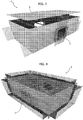
- FIG. 1 a portion of a floating breakwater dam manufactured using the method of the invention is indicated in its entirety with 1.
- the represented configuration is purely by way of example, in that the manufacture of the floating dam, in terms of shape and size, may widely vary according to the design parameters thereof.
- it may be adapted to the construction of floating dams with various geometric shapes and not only designed for breakwater purposes but also for mooring vessels as well as residential settlements or settlements of other types.
- the floating structure manufactured according to the method described in detail hereinafter, has an upper part 1a projecting above the waterline L on the water surface where the floating dam 1 is installed, and a submerged lower part 1b.
- the submerged part 1b shall, for example, be configured and dimensioned as a function of the statistical analysis regarding the predictable wave motion, even in terms of maximum values, regarding the water surface.
- the floating dam 1 may be provided with submerged dummy-bottom tanks 2, with zero hydrostatic pressure, as well as possible floating wharfs 3 anchored to the tanks 2 for mooring vessels.
- Such floating wharfs 3 may for example be of the type described and illustrated in the previously mentioned European patent EP-0905324 B1 on behalf of the Applicant.
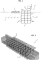
- the floating dam 1 is formed by a plurality of modular hollow bodies 4 one of which is schematically represented in figures 2 to 4 .
- Each modular body 4 is formed by a generally parallelepiped-shaped pre-fabricated tank conveniently manufactured using ship building techniques with ferro-cement. Other similar composite materials, may also be used. In an embodiment not covered by the present invention, ironwood may be used as a material for the modular body 4.
- Typical dimensions may for example be 20 m (length), 5 m (width) and 4 m (height), with a 4 cm wall thickness.
- Transversal stiffening septa or ribs 5 may be provided for in the module 4 for example with a 1 m pitch, and - as regards the modules 4 designed to be positioned above the waterline L - apertures for access to possible internal service gaps may be provided for.
- the required reinforcing rods shall be established during the planning stage and thus they are variable in terms of density and thickness and they may be, in an embodiment not covered by the present invention, absent for some modular bodies 4 or parts thereof, for example in cases where they can be mechanically joined with contiguous modular bodies 4, through pins or rods, and/or by gluing.
- Figure 2 shows the arrangement of the longitudinal, transversal and vertical reinforcing rods of each module 4, at least partly projecting outwards for joining with the contiguous modules 4 by means of the methods outlined hereinafter.
- Figures 3 and 4 show an exemplary preferred embodiment of the modular body 4 which is provided, at at least one of the walls thereof, with an annular spacer member 6 projecting outwards for reasons to be outlined hereinafter.
- the annular spacer member 6 also allows providing an intercommunication passage between the module 4 and the contiguous module/s 4 after composition thereof.
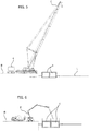
- the methods for manufacturing the floating dam 1 are exemplified in succession in figures 5-12 , described hereinafter.
- the modular hollow bodies 4 are pre-fabricated and thus moved to a quay B one at a time so as to be lifted, by means of a crane G, and transferred to the water surface.
- the first step ( figure 5 ) consists of laying a first group of said modular bodies 4 to float near the quay B in mutual side-to-side arrangement so as to delimit therebetween intermediate gaps within which the respective longitudinal and transversal reinforcing rods are protruding as schematically illustrated in figure 8 , in which one of such gaps is indicated with 7.
- Such gap 7 is for example defined by the coupling of the spacer members 6 of the modules 4, illustrated in figures 3 and 4 , also serving as positioning members.
- These spacer/positioning members 6 may define intercommunication passages or wire and pipe passages between the contiguous modular bodies 4, and they may be of various and several types, with different shapes depending on the planning requirements.
- the modules 4 of the first group are mutually joined through a first concrete casting, by means of a first concrete mixer pump truck P, so as to obtain vertical counter-walls which embody spacer members 6, and an upper horizontal slab.
- a particularly fluid but quick drying concrete is used.
- possible conventional formworks or formworks made of ferro-cement panels or other material, serving as disposable formworks are used.
- the subsequent step ( figure 7 ) consists of laying a second group of modular bodies 4 on the first group and performing a second concrete casting in order to join the first and second group together.
- Possible dummy-bottom tanks 2 ( figure 9 ), to be subsequently joined to the floating dam 1 for a better stabilisation thereof as well as for obtaining a more efficient reduction of the wave motion, are then laid.
- the subsequent step ( figure 10 ) consists of a controlled flooding of at least part of the first group of modular bodies 4 so as to lower the second group and then proceeding to lay a third group of modular bodies 4 ( figure 11 ), which are then joined to the second group through a further concrete casting ( figure 12 ).
- the controlled flooding stage may for example be obtained through the methods described in the aforementioned Italian patent n° TO2012A000216 , or other systems known to a man skilled in the art.
- FIGS 13 and 14 schematically show possible examples of configurations of the various groups of modular bodies 4 with the respective reinforcing rods and the relative spacer members 6.
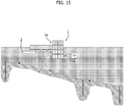
- the floating dam 1 is dragged to the site it is meant to be positioned and then it is anchored to the floor by means of conventional systems with piles and chains, as schematically illustrated in figure 15 .
- Figures 16 and 17 show two examples of possible planimetric configurations of a composite floating island manufactured according to the invention, in which two concentric circular dams are provided to protect a group of residential, commercial and service floating modules.
- the circular dams shall be provided with wind and/or photovoltaic and/or turbine wells systems for generating electricity, as well as water purification plants and other service equipment.
- the floating dam or island according to the invention allows attaining several advantages with respect to conventional solutions with permanent structure obtained by means of conventional construction techniques: Besides the aforementioned advantages, lying in the fact that the structure is simple and inexpensive to construct, easy to move or remove as well as its low environmental impact, another advantage lies in the fact that the configuration of the modular hollow bodies that form the structure allows the construction thereof in industrial plants with elementary equipment, and the subsequent transfer to the site of installation by means of entirely ordinary means, thus further reducing the environmental impact.
- contiguous modular hollow bodies 4 may also be mutually joined by means of mechanical systems and/or gluing.
Landscapes
- Engineering & Computer Science (AREA)
- General Engineering & Computer Science (AREA)
- Mechanical Engineering (AREA)
- Ocean & Marine Engineering (AREA)
- Civil Engineering (AREA)
- Structural Engineering (AREA)
- Chemical & Material Sciences (AREA)
- Combustion & Propulsion (AREA)
- Environmental & Geological Engineering (AREA)
- Architecture (AREA)
- Revetment (AREA)
Claims (9)
- Verfahren zur Herstellung eines/r schwimmenden Damms oder Insel (1) durch- Vorfertigen einer Mehrzahl von modularen Hohlkörpern (4), die im Allgemeinen eine Parallelepiped-Form aufweisen und aus Ferrozement oder ähnlichen Materialien hergestellt sind, mit längs, quer und vertikal verlaufenden Bewehrungsstangen, die zumindest teilweise nach außen vorstehen,dadurch gekennzeichnet, dass das Verfahren ferner die folgenden Schritte umfasst:- Legen einer ersten Gruppe der modularen Körper (4) so, dass sie auf einer Wasseroberfläche schwimmen, Positionieren der modularen Körper (4) in einer Nebeneinanderanordnung, um dazwischen Zwischenspalte (7) zu begrenzen, innerhalb derer die Bewehrungsstangen vorstehen;- Ausführen eines ersten Betongießvorgangs in die Spalte (7) und über die modularen Körper (4), um sie durch vertikale Gegenwände und eine horizontale Platte miteinander zu verbinden,- Legen einer zweiten Gruppe der modularen Körper (4) über die erste Gruppe und Ausführen eines zweiten Betongießvorgangs, um die erste und zweite Gruppe miteinander zu verbinden,- Fortfahren auf die gleiche Weise durch Legen zusätzlicher Gruppen modularer Körper (4) und Ausführen weiterer Betongießvorgänge bis zum Erhalt eines monolithischen Blocks, der die gewünschte Konfiguration eines/r schwimmenden Damms oder Insel (1) aufweist,wobei dem Schritt des Legens zumindest eines Teils der zusätzlichen Gruppen modularer Körper (4) eine Phase für das kontrollierte Überfluten der darunterliegenden modularen Körper (4) vorausgeht.
- Verfahren nach Anspruch 1, dadurch gekennzeichnet, dass zwischen den nebeneinanderliegenden modularen Körpern (4) Abstandsmittel (6) bereitgestellt sind, die dafür ausgelegt sind, innerhalb der Betonierungen ausgeführt zu sein.
- Verfahren nach Anspruch 2, dadurch gekennzeichnet, dass die Abstandsmittel (6) einstückig mit den modularen Körpern (4) ausgebildet sind.
- Verfahren nach Anspruch 3, dadurch gekennzeichnet, dass die Abstandsmittel aus ringförmigen Elementen (6) bestehen, die von den Seitenwänden der modularen Körper (4) an entsprechenden Zwischenverbindungsöffnungen vorstehen.
- Verfahren nach einem oder mehreren der vorangehenden Ansprüche, dadurch gekennzeichnet, dass die modularen Körper (4) mit inneren Verstärkungsrippen (5) ausgebildet sind.
- Verfahren nach einem oder mehreren der vorangehenden Ansprüche, dadurch gekennzeichnet, dass es ferner den Schritt eines Bereitstellens und Anbringens untergetauchter Pseudoboden-Tanks (2) zum Stabilisieren des/r schwimmenden Damms oder Insel (1) umfasst.
- Verfahren nach einem oder mehreren der vorangehenden Ansprüche, dadurch gekennzeichnet, dass es ferner den Schritt eines Bereitstellens permanenter Verankerungen des/r schwimmenden Damms oder Insel (1) umfasst.
- Verfahren nach einem oder mehreren der vorangehenden Ansprüche, dadurch gekennzeichnet, dass es ferner den Schritt eines Bereitstellens von schwimmenden Kais (3), die mit dem/r schwimmenden Damm oder Insel (1) verbunden sind, umfasst.
- Schwimmender Damm oder Insel (1), der/die gemäß einem der vorangehenden Ansprüche hergestellt wird.
Applications Claiming Priority (2)
| Application Number | Priority Date | Filing Date | Title |
|---|---|---|---|
| ITTO20140801 | 2014-10-08 | ||
| PCT/IB2015/057702 WO2016055965A1 (en) | 2014-10-08 | 2015-10-08 | Floating dam or island and method of manufacture thereof |
Publications (2)
| Publication Number | Publication Date |
|---|---|
| EP3204559A1 EP3204559A1 (de) | 2017-08-16 |
| EP3204559B1 true EP3204559B1 (de) | 2018-12-12 |
Family
ID=52101505
Family Applications (1)
| Application Number | Title | Priority Date | Filing Date |
|---|---|---|---|
| EP15790277.6A Active EP3204559B1 (de) | 2014-10-08 | 2015-10-08 | Schwimmender damm oder insel und verfahren zur herstellung davon |
Country Status (4)
| Country | Link |
|---|---|
| US (1) | US10024013B2 (de) |
| EP (1) | EP3204559B1 (de) |
| CN (1) | CN107002376B (de) |
| WO (1) | WO2016055965A1 (de) |
Cited By (1)
| Publication number | Priority date | Publication date | Assignee | Title |
|---|---|---|---|---|
| TWI694035B (zh) * | 2019-02-21 | 2020-05-21 | 陳光正 | 多功能生態浮島與多功能生態浮島組合 |
Families Citing this family (10)
| Publication number | Priority date | Publication date | Assignee | Title |
|---|---|---|---|---|
| RU2699462C1 (ru) * | 2018-07-27 | 2019-09-05 | Федеральное государственное бюджетное образовательное учреждение высшего образования "Национальный исследовательский Московский государственный строительный университет" (НИУ МГСУ) | Способ изготовления водоизмещающих бетонных изделий |
| TWI767158B (zh) * | 2019-04-02 | 2022-06-11 | 國立臺灣海洋大學 | 消波船 |
| CN110080169B (zh) * | 2019-04-03 | 2020-11-24 | 温州大学 | 一种基于地下室利用的围海造地的施工方法 |
| IL268914B (en) * | 2019-08-26 | 2022-08-01 | Israel Ports Dev & Assets Company Ltd | A marine construction and a method for constructing the same |
| GB2601135B (en) | 2020-11-18 | 2025-01-15 | Desmond Fitzgerald Calum | Carbon sequestration apparatus |
| GB2634415B (en) * | 2020-11-18 | 2025-08-06 | t allen John | Carbon sequestration apparatus |
| CN112623127B (zh) * | 2020-12-14 | 2022-03-29 | 清华大学 | 应用于深海远洋的自浮式模板及混凝土浮岛建造下水方法 |
| CN112550634B (zh) * | 2020-12-14 | 2022-03-22 | 江苏巨鑫石油钢管有限公司 | 应用于深海远洋的混凝土浮岛现场建造装置及施工方法 |
| CN114622516B (zh) * | 2022-04-02 | 2024-01-23 | 黄河勘测规划设计研究院有限公司 | 一种具有河道控导作用的新型生态码头及其设计方法 |
| CN119037648A (zh) * | 2024-10-17 | 2024-11-29 | 清华大学 | 浮式结构基础的模板体系及混凝土浮式基础快速成型方法 |
Citations (2)
| Publication number | Priority date | Publication date | Assignee | Title |
|---|---|---|---|---|
| US2645114A (en) * | 1945-10-18 | 1953-07-14 | Amirikian Arsham | Hollow structure |
| DE1784905A1 (de) * | 1962-12-29 | 1971-11-11 | Lowe & Rodin | Gebaeude in Raumkastenbauweise |
Family Cites Families (9)
| Publication number | Priority date | Publication date | Assignee | Title |
|---|---|---|---|---|
| JPS4918394B1 (de) * | 1969-06-05 | 1974-05-09 | ||
| SE8007162L (sv) * | 1980-10-13 | 1982-04-14 | Goetaverken Arendal Ab | Flytdocka |
| US5379559A (en) * | 1991-11-29 | 1995-01-10 | Niimura; Masateru | Semisubmersible building |
| US5740753A (en) * | 1995-10-24 | 1998-04-21 | Theophanis; Peter M. | Method of fabricating buoyant prestressed concrete building modules, resulting modules, and assembly thereof |
| IT1295440B1 (it) | 1997-09-26 | 1999-05-12 | Giorgio Salis | Pontile o molo galleggiante per l'attracco di imbarcazioni. |
| US6058869A (en) | 1997-11-25 | 2000-05-09 | Thon; Ralph C. | Floating pontoon structure with adjustable draft |
| US7242107B1 (en) * | 2003-03-17 | 2007-07-10 | Harry Edward Dempster | Water-based wind-driven power generation using a submerged platform |
| ITTO20120216A1 (it) * | 2012-03-12 | 2013-09-13 | Giorgio Salis | Modulo a dislocamento variabile per pontili, moli e dighe galleggianti |
| CN102910263A (zh) * | 2012-10-08 | 2013-02-06 | 杜卫冲 | 平台构造组件和水上浮动结构及其制备方法 |
-
2015
- 2015-10-08 EP EP15790277.6A patent/EP3204559B1/de active Active
- 2015-10-08 WO PCT/IB2015/057702 patent/WO2016055965A1/en not_active Ceased
- 2015-10-08 US US15/517,787 patent/US10024013B2/en active Active
- 2015-10-08 CN CN201580054763.7A patent/CN107002376B/zh active Active
Patent Citations (2)
| Publication number | Priority date | Publication date | Assignee | Title |
|---|---|---|---|---|
| US2645114A (en) * | 1945-10-18 | 1953-07-14 | Amirikian Arsham | Hollow structure |
| DE1784905A1 (de) * | 1962-12-29 | 1971-11-11 | Lowe & Rodin | Gebaeude in Raumkastenbauweise |
Cited By (1)
| Publication number | Priority date | Publication date | Assignee | Title |
|---|---|---|---|---|
| TWI694035B (zh) * | 2019-02-21 | 2020-05-21 | 陳光正 | 多功能生態浮島與多功能生態浮島組合 |
Also Published As
| Publication number | Publication date |
|---|---|
| CN107002376A (zh) | 2017-08-01 |
| WO2016055965A1 (en) | 2016-04-14 |
| US20170306579A1 (en) | 2017-10-26 |
| US10024013B2 (en) | 2018-07-17 |
| CN107002376B (zh) | 2019-09-10 |
| EP3204559A1 (de) | 2017-08-16 |
Similar Documents
| Publication | Publication Date | Title |
|---|---|---|
| EP3204559B1 (de) | Schwimmender damm oder insel und verfahren zur herstellung davon | |
| US20260015811A1 (en) | Suction Anchors and Their Methods of Manufacture | |
| EP2837554A1 (de) | Teilweise schwimmende meeresplattform für offshore-windkraftanlage, brücken und meeresgebäude sowie konstruktionsverfahren | |
| US11946216B2 (en) | Additive manufacturing of support structures | |
| CN103255752B (zh) | 支撑海上风机、海洋建筑物的浮力支撑固定平台 | |
| AU2017253505B2 (en) | Sea wall structures, sea walls and methods of manufacture and assembly of the same | |
| US10400407B2 (en) | Modular wave-break and bulkhead system | |
| KR20230162941A (ko) | 해상 풍력 터빈용 기초 | |
| CN204491641U (zh) | 挡水墙单元和自平衡围堰结构 | |
| KR20140092217A (ko) | 작업선을 이용한 교각의 수중설치공법. | |
| US20220162825A1 (en) | Method for the installation of an offshore maritime structure and offshore maritime structure | |
| JP7389893B2 (ja) | 海上構造及び建設方法 | |
| KR100227536B1 (ko) | 벨 타입 강각(鋼殼) 케이슨 공법 | |
| CN205502042U (zh) | 近堤高水位差复合式钢板桩围堰水中承台 | |
| CN105040661B (zh) | 用于建造人工岛的钢模及施工方法 | |
| JP7597618B2 (ja) | 水中における構造物の施工方法 | |
| JP2003020634A (ja) | 水路の施工方法 | |
| EP3879035A1 (de) | Meeresfundament, anordnung, verwendung eines meeresfundaments und verfahren zur installation und deinstallation eines meeresfundaments | |
| JPH06257163A (ja) | 浅水深基礎工事用渇水台船 | |
| JP2024508480A (ja) | 浮遊可能なコンクリートブロック構造物及びその製作方法 | |
| CN114108555A (zh) | 一种河道抢险吸力式组合桩坝施工方法 | |
| JP5797181B2 (ja) | 岸壁補修工法 | |
| CN114086513A (zh) | 一种河道抢险吸力式组合桩坝结构 | |
| JPH1018297A (ja) | ケーソン据え付けに伴う水中コンクリート及び砂の漏洩防止工法 |
Legal Events
| Date | Code | Title | Description |
|---|---|---|---|
| STAA | Information on the status of an ep patent application or granted ep patent |
Free format text: STATUS: THE INTERNATIONAL PUBLICATION HAS BEEN MADE |
|
| PUAI | Public reference made under article 153(3) epc to a published international application that has entered the european phase |
Free format text: ORIGINAL CODE: 0009012 |
|
| STAA | Information on the status of an ep patent application or granted ep patent |
Free format text: STATUS: REQUEST FOR EXAMINATION WAS MADE |
|
| 17P | Request for examination filed |
Effective date: 20170407 |
|
| AK | Designated contracting states |
Kind code of ref document: A1 Designated state(s): AL AT BE BG CH CY CZ DE DK EE ES FI FR GB GR HR HU IE IS IT LI LT LU LV MC MK MT NL NO PL PT RO RS SE SI SK SM TR |
|
| AX | Request for extension of the european patent |
Extension state: BA ME |
|
| DAV | Request for validation of the european patent (deleted) | ||
| DAX | Request for extension of the european patent (deleted) | ||
| REG | Reference to a national code |
Ref country code: DE Ref legal event code: R079 Ref document number: 602015021561 Country of ref document: DE Free format text: PREVIOUS MAIN CLASS: E02B0003060000 Ipc: B63B0035440000 |
|
| GRAP | Despatch of communication of intention to grant a patent |
Free format text: ORIGINAL CODE: EPIDOSNIGR1 |
|
| STAA | Information on the status of an ep patent application or granted ep patent |
Free format text: STATUS: GRANT OF PATENT IS INTENDED |
|
| RIC1 | Information provided on ipc code assigned before grant |
Ipc: B63B 35/44 20060101AFI20180704BHEP Ipc: B63B 35/38 20060101ALI20180704BHEP Ipc: B63B 5/14 20060101ALI20180704BHEP Ipc: E02B 3/06 20060101ALI20180704BHEP |
|
| INTG | Intention to grant announced |
Effective date: 20180716 |
|
| GRAS | Grant fee paid |
Free format text: ORIGINAL CODE: EPIDOSNIGR3 |
|
| GRAA | (expected) grant |
Free format text: ORIGINAL CODE: 0009210 |
|
| STAA | Information on the status of an ep patent application or granted ep patent |
Free format text: STATUS: THE PATENT HAS BEEN GRANTED |
|
| AK | Designated contracting states |
Kind code of ref document: B1 Designated state(s): AL AT BE BG CH CY CZ DE DK EE ES FI FR GB GR HR HU IE IS IT LI LT LU LV MC MK MT NL NO PL PT RO RS SE SI SK SM TR |
|
| REG | Reference to a national code |
Ref country code: GB Ref legal event code: FG4D |
|
| REG | Reference to a national code |
Ref country code: CH Ref legal event code: EP |
|
| REG | Reference to a national code |
Ref country code: AT Ref legal event code: REF Ref document number: 1075612 Country of ref document: AT Kind code of ref document: T Effective date: 20181215 |
|
| REG | Reference to a national code |
Ref country code: DE Ref legal event code: R096 Ref document number: 602015021561 Country of ref document: DE |
|
| REG | Reference to a national code |
Ref country code: IE Ref legal event code: FG4D |
|
| REG | Reference to a national code |
Ref country code: NL Ref legal event code: FP |
|
| REG | Reference to a national code |
Ref country code: LT Ref legal event code: MG4D |
|
| PG25 | Lapsed in a contracting state [announced via postgrant information from national office to epo] |
Ref country code: NO Free format text: LAPSE BECAUSE OF FAILURE TO SUBMIT A TRANSLATION OF THE DESCRIPTION OR TO PAY THE FEE WITHIN THE PRESCRIBED TIME-LIMIT Effective date: 20190312 Ref country code: LV Free format text: LAPSE BECAUSE OF FAILURE TO SUBMIT A TRANSLATION OF THE DESCRIPTION OR TO PAY THE FEE WITHIN THE PRESCRIBED TIME-LIMIT Effective date: 20181212 Ref country code: FI Free format text: LAPSE BECAUSE OF FAILURE TO SUBMIT A TRANSLATION OF THE DESCRIPTION OR TO PAY THE FEE WITHIN THE PRESCRIBED TIME-LIMIT Effective date: 20181212 Ref country code: LT Free format text: LAPSE BECAUSE OF FAILURE TO SUBMIT A TRANSLATION OF THE DESCRIPTION OR TO PAY THE FEE WITHIN THE PRESCRIBED TIME-LIMIT Effective date: 20181212 Ref country code: HR Free format text: LAPSE BECAUSE OF FAILURE TO SUBMIT A TRANSLATION OF THE DESCRIPTION OR TO PAY THE FEE WITHIN THE PRESCRIBED TIME-LIMIT Effective date: 20181212 Ref country code: BG Free format text: LAPSE BECAUSE OF FAILURE TO SUBMIT A TRANSLATION OF THE DESCRIPTION OR TO PAY THE FEE WITHIN THE PRESCRIBED TIME-LIMIT Effective date: 20190312 |
|
| REG | Reference to a national code |
Ref country code: AT Ref legal event code: MK05 Ref document number: 1075612 Country of ref document: AT Kind code of ref document: T Effective date: 20181212 |
|
| PG25 | Lapsed in a contracting state [announced via postgrant information from national office to epo] |
Ref country code: SE Free format text: LAPSE BECAUSE OF FAILURE TO SUBMIT A TRANSLATION OF THE DESCRIPTION OR TO PAY THE FEE WITHIN THE PRESCRIBED TIME-LIMIT Effective date: 20181212 Ref country code: AL Free format text: LAPSE BECAUSE OF FAILURE TO SUBMIT A TRANSLATION OF THE DESCRIPTION OR TO PAY THE FEE WITHIN THE PRESCRIBED TIME-LIMIT Effective date: 20181212 Ref country code: RS Free format text: LAPSE BECAUSE OF FAILURE TO SUBMIT A TRANSLATION OF THE DESCRIPTION OR TO PAY THE FEE WITHIN THE PRESCRIBED TIME-LIMIT Effective date: 20181212 |
|
| REG | Reference to a national code |
Ref country code: GR Ref legal event code: EP Ref document number: 20190400792 Country of ref document: GR Effective date: 20190524 |
|
| PG25 | Lapsed in a contracting state [announced via postgrant information from national office to epo] |
Ref country code: PL Free format text: LAPSE BECAUSE OF FAILURE TO SUBMIT A TRANSLATION OF THE DESCRIPTION OR TO PAY THE FEE WITHIN THE PRESCRIBED TIME-LIMIT Effective date: 20181212 Ref country code: ES Free format text: LAPSE BECAUSE OF FAILURE TO SUBMIT A TRANSLATION OF THE DESCRIPTION OR TO PAY THE FEE WITHIN THE PRESCRIBED TIME-LIMIT Effective date: 20181212 Ref country code: IT Free format text: LAPSE BECAUSE OF FAILURE TO SUBMIT A TRANSLATION OF THE DESCRIPTION OR TO PAY THE FEE WITHIN THE PRESCRIBED TIME-LIMIT Effective date: 20181212 Ref country code: CZ Free format text: LAPSE BECAUSE OF FAILURE TO SUBMIT A TRANSLATION OF THE DESCRIPTION OR TO PAY THE FEE WITHIN THE PRESCRIBED TIME-LIMIT Effective date: 20181212 Ref country code: PT Free format text: LAPSE BECAUSE OF FAILURE TO SUBMIT A TRANSLATION OF THE DESCRIPTION OR TO PAY THE FEE WITHIN THE PRESCRIBED TIME-LIMIT Effective date: 20190412 |
|
| PG25 | Lapsed in a contracting state [announced via postgrant information from national office to epo] |
Ref country code: SK Free format text: LAPSE BECAUSE OF FAILURE TO SUBMIT A TRANSLATION OF THE DESCRIPTION OR TO PAY THE FEE WITHIN THE PRESCRIBED TIME-LIMIT Effective date: 20181212 Ref country code: IS Free format text: LAPSE BECAUSE OF FAILURE TO SUBMIT A TRANSLATION OF THE DESCRIPTION OR TO PAY THE FEE WITHIN THE PRESCRIBED TIME-LIMIT Effective date: 20190412 Ref country code: RO Free format text: LAPSE BECAUSE OF FAILURE TO SUBMIT A TRANSLATION OF THE DESCRIPTION OR TO PAY THE FEE WITHIN THE PRESCRIBED TIME-LIMIT Effective date: 20181212 Ref country code: SM Free format text: LAPSE BECAUSE OF FAILURE TO SUBMIT A TRANSLATION OF THE DESCRIPTION OR TO PAY THE FEE WITHIN THE PRESCRIBED TIME-LIMIT Effective date: 20181212 Ref country code: EE Free format text: LAPSE BECAUSE OF FAILURE TO SUBMIT A TRANSLATION OF THE DESCRIPTION OR TO PAY THE FEE WITHIN THE PRESCRIBED TIME-LIMIT Effective date: 20181212 |
|
| REG | Reference to a national code |
Ref country code: DE Ref legal event code: R097 Ref document number: 602015021561 Country of ref document: DE |
|
| PLBE | No opposition filed within time limit |
Free format text: ORIGINAL CODE: 0009261 |
|
| STAA | Information on the status of an ep patent application or granted ep patent |
Free format text: STATUS: NO OPPOSITION FILED WITHIN TIME LIMIT |
|
| PG25 | Lapsed in a contracting state [announced via postgrant information from national office to epo] |
Ref country code: SI Free format text: LAPSE BECAUSE OF FAILURE TO SUBMIT A TRANSLATION OF THE DESCRIPTION OR TO PAY THE FEE WITHIN THE PRESCRIBED TIME-LIMIT Effective date: 20181212 Ref country code: DK Free format text: LAPSE BECAUSE OF FAILURE TO SUBMIT A TRANSLATION OF THE DESCRIPTION OR TO PAY THE FEE WITHIN THE PRESCRIBED TIME-LIMIT Effective date: 20181212 Ref country code: AT Free format text: LAPSE BECAUSE OF FAILURE TO SUBMIT A TRANSLATION OF THE DESCRIPTION OR TO PAY THE FEE WITHIN THE PRESCRIBED TIME-LIMIT Effective date: 20181212 |
|
| 26N | No opposition filed |
Effective date: 20190913 |
|
| PG25 | Lapsed in a contracting state [announced via postgrant information from national office to epo] |
Ref country code: TR Free format text: LAPSE BECAUSE OF FAILURE TO SUBMIT A TRANSLATION OF THE DESCRIPTION OR TO PAY THE FEE WITHIN THE PRESCRIBED TIME-LIMIT Effective date: 20181212 |
|
| PG25 | Lapsed in a contracting state [announced via postgrant information from national office to epo] |
Ref country code: MC Free format text: LAPSE BECAUSE OF FAILURE TO SUBMIT A TRANSLATION OF THE DESCRIPTION OR TO PAY THE FEE WITHIN THE PRESCRIBED TIME-LIMIT Effective date: 20181212 |
|
| REG | Reference to a national code |
Ref country code: CH Ref legal event code: PL |
|
| PG25 | Lapsed in a contracting state [announced via postgrant information from national office to epo] |
Ref country code: LI Free format text: LAPSE BECAUSE OF NON-PAYMENT OF DUE FEES Effective date: 20191031 Ref country code: CH Free format text: LAPSE BECAUSE OF NON-PAYMENT OF DUE FEES Effective date: 20191031 Ref country code: LU Free format text: LAPSE BECAUSE OF NON-PAYMENT OF DUE FEES Effective date: 20191008 |
|
| PG25 | Lapsed in a contracting state [announced via postgrant information from national office to epo] |
Ref country code: IE Free format text: LAPSE BECAUSE OF NON-PAYMENT OF DUE FEES Effective date: 20191008 |
|
| PG25 | Lapsed in a contracting state [announced via postgrant information from national office to epo] |
Ref country code: CY Free format text: LAPSE BECAUSE OF FAILURE TO SUBMIT A TRANSLATION OF THE DESCRIPTION OR TO PAY THE FEE WITHIN THE PRESCRIBED TIME-LIMIT Effective date: 20181212 |
|
| PG25 | Lapsed in a contracting state [announced via postgrant information from national office to epo] |
Ref country code: MT Free format text: LAPSE BECAUSE OF FAILURE TO SUBMIT A TRANSLATION OF THE DESCRIPTION OR TO PAY THE FEE WITHIN THE PRESCRIBED TIME-LIMIT Effective date: 20181212 Ref country code: HU Free format text: LAPSE BECAUSE OF FAILURE TO SUBMIT A TRANSLATION OF THE DESCRIPTION OR TO PAY THE FEE WITHIN THE PRESCRIBED TIME-LIMIT; INVALID AB INITIO Effective date: 20151008 |
|
| PG25 | Lapsed in a contracting state [announced via postgrant information from national office to epo] |
Ref country code: MK Free format text: LAPSE BECAUSE OF FAILURE TO SUBMIT A TRANSLATION OF THE DESCRIPTION OR TO PAY THE FEE WITHIN THE PRESCRIBED TIME-LIMIT Effective date: 20181212 |
|
| PGFP | Annual fee paid to national office [announced via postgrant information from national office to epo] |
Ref country code: NL Payment date: 20241023 Year of fee payment: 10 |
|
| PGFP | Annual fee paid to national office [announced via postgrant information from national office to epo] |
Ref country code: DE Payment date: 20241029 Year of fee payment: 10 |
|
| PGFP | Annual fee paid to national office [announced via postgrant information from national office to epo] |
Ref country code: BE Payment date: 20241023 Year of fee payment: 10 Ref country code: GR Payment date: 20241021 Year of fee payment: 10 |
|
| PGFP | Annual fee paid to national office [announced via postgrant information from national office to epo] |
Ref country code: GB Payment date: 20241022 Year of fee payment: 10 |
|
| PGFP | Annual fee paid to national office [announced via postgrant information from national office to epo] |
Ref country code: FR Payment date: 20241025 Year of fee payment: 10 |