EP3204183B1 - Échangeur de chaleur brasé - Google Patents
Échangeur de chaleur brasé Download PDFInfo
- Publication number
- EP3204183B1 EP3204183B1 EP15849290.0A EP15849290A EP3204183B1 EP 3204183 B1 EP3204183 B1 EP 3204183B1 EP 15849290 A EP15849290 A EP 15849290A EP 3204183 B1 EP3204183 B1 EP 3204183B1
- Authority
- EP
- European Patent Office
- Prior art keywords
- heat exchanger
- ducts
- braze
- plates
- brazed heat
- Prior art date
- Legal status (The legal status is an assumption and is not a legal conclusion. Google has not performed a legal analysis and makes no representation as to the accuracy of the status listed.)
- Active
Links
- 239000000463 material Substances 0.000 claims description 127
- 229910000831 Steel Inorganic materials 0.000 claims description 7
- 239000010959 steel Substances 0.000 claims description 7
- 239000000203 mixture Substances 0.000 claims description 6
- 238000002844 melting Methods 0.000 claims description 4
- 230000008018 melting Effects 0.000 claims description 4
- 238000005219 brazing Methods 0.000 description 68
- 239000010949 copper Substances 0.000 description 44
- 229910052802 copper Inorganic materials 0.000 description 33
- XEEYBQQBJWHFJM-UHFFFAOYSA-N iron Substances [Fe] XEEYBQQBJWHFJM-UHFFFAOYSA-N 0.000 description 33
- RYGMFSIKBFXOCR-UHFFFAOYSA-N Copper Chemical compound [Cu] RYGMFSIKBFXOCR-UHFFFAOYSA-N 0.000 description 29
- 239000003921 oil Substances 0.000 description 23
- 238000000034 method Methods 0.000 description 15
- 229910052742 iron Inorganic materials 0.000 description 14
- 239000000126 substance Substances 0.000 description 14
- 239000007788 liquid Substances 0.000 description 13
- 229910045601 alloy Inorganic materials 0.000 description 12
- 239000000956 alloy Substances 0.000 description 12
- 239000000470 constituent Substances 0.000 description 12
- 239000000110 cooling liquid Substances 0.000 description 11
- 238000004519 manufacturing process Methods 0.000 description 10
- 239000011888 foil Substances 0.000 description 7
- 229910052751 metal Inorganic materials 0.000 description 5
- 239000000843 powder Substances 0.000 description 5
- 238000004090 dissolution Methods 0.000 description 4
- 239000002184 metal Substances 0.000 description 4
- 238000007747 plating Methods 0.000 description 4
- 230000015572 biosynthetic process Effects 0.000 description 2
- 229910052804 chromium Inorganic materials 0.000 description 2
- 239000002826 coolant Substances 0.000 description 2
- 230000008878 coupling Effects 0.000 description 2
- 238000010168 coupling process Methods 0.000 description 2
- 238000005859 coupling reaction Methods 0.000 description 2
- 229910052759 nickel Inorganic materials 0.000 description 2
- 229910000838 Al alloy Inorganic materials 0.000 description 1
- 229910018125 Al-Si Inorganic materials 0.000 description 1
- 229910018520 Al—Si Inorganic materials 0.000 description 1
- 229910052782 aluminium Inorganic materials 0.000 description 1
- XAGFODPZIPBFFR-UHFFFAOYSA-N aluminium Chemical compound [Al] XAGFODPZIPBFFR-UHFFFAOYSA-N 0.000 description 1
- 238000006243 chemical reaction Methods 0.000 description 1
- 239000011248 coating agent Substances 0.000 description 1
- 238000000576 coating method Methods 0.000 description 1
- 238000010276 construction Methods 0.000 description 1
- 230000007797 corrosion Effects 0.000 description 1
- 238000005260 corrosion Methods 0.000 description 1
- 238000002788 crimping Methods 0.000 description 1
- 230000001419 dependent effect Effects 0.000 description 1
- 230000000694 effects Effects 0.000 description 1
- 229910052748 manganese Inorganic materials 0.000 description 1
- 238000007650 screen-printing Methods 0.000 description 1
- 229910052710 silicon Inorganic materials 0.000 description 1
- 239000011343 solid material Substances 0.000 description 1
- 239000010935 stainless steel Substances 0.000 description 1
- 229910001220 stainless steel Inorganic materials 0.000 description 1
- 238000003466 welding Methods 0.000 description 1
Images


Classifications
-
- F—MECHANICAL ENGINEERING; LIGHTING; HEATING; WEAPONS; BLASTING
- F28—HEAT EXCHANGE IN GENERAL
- F28D—HEAT-EXCHANGE APPARATUS, NOT PROVIDED FOR IN ANOTHER SUBCLASS, IN WHICH THE HEAT-EXCHANGE MEDIA DO NOT COME INTO DIRECT CONTACT
- F28D9/00—Heat-exchange apparatus having stationary plate-like or laminated conduit assemblies for both heat-exchange media, the media being in contact with different sides of a conduit wall
- F28D9/0031—Heat-exchange apparatus having stationary plate-like or laminated conduit assemblies for both heat-exchange media, the media being in contact with different sides of a conduit wall the conduits for one heat-exchange medium being formed by paired plates touching each other
- F28D9/0043—Heat-exchange apparatus having stationary plate-like or laminated conduit assemblies for both heat-exchange media, the media being in contact with different sides of a conduit wall the conduits for one heat-exchange medium being formed by paired plates touching each other the plates having openings therein for circulation of at least one heat-exchange medium from one conduit to another
- F28D9/005—Heat-exchange apparatus having stationary plate-like or laminated conduit assemblies for both heat-exchange media, the media being in contact with different sides of a conduit wall the conduits for one heat-exchange medium being formed by paired plates touching each other the plates having openings therein for circulation of at least one heat-exchange medium from one conduit to another the plates having openings therein for both heat-exchange media
-
- B—PERFORMING OPERATIONS; TRANSPORTING
- B23—MACHINE TOOLS; METAL-WORKING NOT OTHERWISE PROVIDED FOR
- B23K—SOLDERING OR UNSOLDERING; WELDING; CLADDING OR PLATING BY SOLDERING OR WELDING; CUTTING BY APPLYING HEAT LOCALLY, e.g. FLAME CUTTING; WORKING BY LASER BEAM
- B23K1/00—Soldering, e.g. brazing, or unsoldering
- B23K1/0008—Soldering, e.g. brazing, or unsoldering specially adapted for particular articles or work
- B23K1/0012—Brazing heat exchangers
-
- B—PERFORMING OPERATIONS; TRANSPORTING
- B23—MACHINE TOOLS; METAL-WORKING NOT OTHERWISE PROVIDED FOR
- B23K—SOLDERING OR UNSOLDERING; WELDING; CLADDING OR PLATING BY SOLDERING OR WELDING; CUTTING BY APPLYING HEAT LOCALLY, e.g. FLAME CUTTING; WORKING BY LASER BEAM
- B23K35/00—Rods, electrodes, materials, or media, for use in soldering, welding, or cutting
- B23K35/02—Rods, electrodes, materials, or media, for use in soldering, welding, or cutting characterised by mechanical features, e.g. shape
- B23K35/0222—Rods, electrodes, materials, or media, for use in soldering, welding, or cutting characterised by mechanical features, e.g. shape for use in soldering, brazing
- B23K35/0233—Sheets, foils
-
- B—PERFORMING OPERATIONS; TRANSPORTING
- B23—MACHINE TOOLS; METAL-WORKING NOT OTHERWISE PROVIDED FOR
- B23K—SOLDERING OR UNSOLDERING; WELDING; CLADDING OR PLATING BY SOLDERING OR WELDING; CUTTING BY APPLYING HEAT LOCALLY, e.g. FLAME CUTTING; WORKING BY LASER BEAM
- B23K35/00—Rods, electrodes, materials, or media, for use in soldering, welding, or cutting
- B23K35/02—Rods, electrodes, materials, or media, for use in soldering, welding, or cutting characterised by mechanical features, e.g. shape
- B23K35/0222—Rods, electrodes, materials, or media, for use in soldering, welding, or cutting characterised by mechanical features, e.g. shape for use in soldering, brazing
- B23K35/0244—Powders, particles or spheres; Preforms made therefrom
- B23K35/025—Pastes, creams, slurries
-
- B—PERFORMING OPERATIONS; TRANSPORTING
- B23—MACHINE TOOLS; METAL-WORKING NOT OTHERWISE PROVIDED FOR
- B23K—SOLDERING OR UNSOLDERING; WELDING; CLADDING OR PLATING BY SOLDERING OR WELDING; CUTTING BY APPLYING HEAT LOCALLY, e.g. FLAME CUTTING; WORKING BY LASER BEAM
- B23K35/00—Rods, electrodes, materials, or media, for use in soldering, welding, or cutting
- B23K35/22—Rods, electrodes, materials, or media, for use in soldering, welding, or cutting characterised by the composition or nature of the material
- B23K35/24—Selection of soldering or welding materials proper
- B23K35/30—Selection of soldering or welding materials proper with the principal constituent melting at less than 1550 degrees C
- B23K35/302—Cu as the principal constituent
-
- B—PERFORMING OPERATIONS; TRANSPORTING
- B23—MACHINE TOOLS; METAL-WORKING NOT OTHERWISE PROVIDED FOR
- B23K—SOLDERING OR UNSOLDERING; WELDING; CLADDING OR PLATING BY SOLDERING OR WELDING; CUTTING BY APPLYING HEAT LOCALLY, e.g. FLAME CUTTING; WORKING BY LASER BEAM
- B23K35/00—Rods, electrodes, materials, or media, for use in soldering, welding, or cutting
- B23K35/22—Rods, electrodes, materials, or media, for use in soldering, welding, or cutting characterised by the composition or nature of the material
- B23K35/24—Selection of soldering or welding materials proper
- B23K35/30—Selection of soldering or welding materials proper with the principal constituent melting at less than 1550 degrees C
- B23K35/3053—Fe as the principal constituent
-
- F—MECHANICAL ENGINEERING; LIGHTING; HEATING; WEAPONS; BLASTING
- F28—HEAT EXCHANGE IN GENERAL
- F28D—HEAT-EXCHANGE APPARATUS, NOT PROVIDED FOR IN ANOTHER SUBCLASS, IN WHICH THE HEAT-EXCHANGE MEDIA DO NOT COME INTO DIRECT CONTACT
- F28D7/00—Heat-exchange apparatus having stationary tubular conduit assemblies for both heat-exchange media, the media being in contact with different sides of a conduit wall
- F28D7/16—Heat-exchange apparatus having stationary tubular conduit assemblies for both heat-exchange media, the media being in contact with different sides of a conduit wall the conduits being arranged in parallel spaced relation
- F28D7/1615—Heat-exchange apparatus having stationary tubular conduit assemblies for both heat-exchange media, the media being in contact with different sides of a conduit wall the conduits being arranged in parallel spaced relation the conduits being inside a casing and extending at an angle to the longitudinal axis of the casing; the conduits crossing the conduit for the other heat exchange medium
-
- F—MECHANICAL ENGINEERING; LIGHTING; HEATING; WEAPONS; BLASTING
- F28—HEAT EXCHANGE IN GENERAL
- F28D—HEAT-EXCHANGE APPARATUS, NOT PROVIDED FOR IN ANOTHER SUBCLASS, IN WHICH THE HEAT-EXCHANGE MEDIA DO NOT COME INTO DIRECT CONTACT
- F28D9/00—Heat-exchange apparatus having stationary plate-like or laminated conduit assemblies for both heat-exchange media, the media being in contact with different sides of a conduit wall
- F28D9/0031—Heat-exchange apparatus having stationary plate-like or laminated conduit assemblies for both heat-exchange media, the media being in contact with different sides of a conduit wall the conduits for one heat-exchange medium being formed by paired plates touching each other
- F28D9/0043—Heat-exchange apparatus having stationary plate-like or laminated conduit assemblies for both heat-exchange media, the media being in contact with different sides of a conduit wall the conduits for one heat-exchange medium being formed by paired plates touching each other the plates having openings therein for circulation of at least one heat-exchange medium from one conduit to another
- F28D9/0056—Heat-exchange apparatus having stationary plate-like or laminated conduit assemblies for both heat-exchange media, the media being in contact with different sides of a conduit wall the conduits for one heat-exchange medium being formed by paired plates touching each other the plates having openings therein for circulation of at least one heat-exchange medium from one conduit to another with U-flow or serpentine-flow inside conduits; with centrally arranged openings on the plates
-
- F—MECHANICAL ENGINEERING; LIGHTING; HEATING; WEAPONS; BLASTING
- F28—HEAT EXCHANGE IN GENERAL
- F28F—DETAILS OF HEAT-EXCHANGE AND HEAT-TRANSFER APPARATUS, OF GENERAL APPLICATION
- F28F21/00—Constructions of heat-exchange apparatus characterised by the selection of particular materials
- F28F21/06—Constructions of heat-exchange apparatus characterised by the selection of particular materials of plastics material
-
- F—MECHANICAL ENGINEERING; LIGHTING; HEATING; WEAPONS; BLASTING
- F28—HEAT EXCHANGE IN GENERAL
- F28F—DETAILS OF HEAT-EXCHANGE AND HEAT-TRANSFER APPARATUS, OF GENERAL APPLICATION
- F28F21/00—Constructions of heat-exchange apparatus characterised by the selection of particular materials
- F28F21/08—Constructions of heat-exchange apparatus characterised by the selection of particular materials of metal
- F28F21/081—Heat exchange elements made from metals or metal alloys
- F28F21/082—Heat exchange elements made from metals or metal alloys from steel or ferrous alloys
-
- F—MECHANICAL ENGINEERING; LIGHTING; HEATING; WEAPONS; BLASTING
- F28—HEAT EXCHANGE IN GENERAL
- F28F—DETAILS OF HEAT-EXCHANGE AND HEAT-TRANSFER APPARATUS, OF GENERAL APPLICATION
- F28F21/00—Constructions of heat-exchange apparatus characterised by the selection of particular materials
- F28F21/08—Constructions of heat-exchange apparatus characterised by the selection of particular materials of metal
- F28F21/081—Heat exchange elements made from metals or metal alloys
- F28F21/084—Heat exchange elements made from metals or metal alloys from aluminium or aluminium alloys
-
- F—MECHANICAL ENGINEERING; LIGHTING; HEATING; WEAPONS; BLASTING
- F28—HEAT EXCHANGE IN GENERAL
- F28F—DETAILS OF HEAT-EXCHANGE AND HEAT-TRANSFER APPARATUS, OF GENERAL APPLICATION
- F28F3/00—Plate-like or laminated elements; Assemblies of plate-like or laminated elements
- F28F3/08—Elements constructed for building-up into stacks, e.g. capable of being taken apart for cleaning
- F28F3/10—Arrangements for sealing the margins
-
- F—MECHANICAL ENGINEERING; LIGHTING; HEATING; WEAPONS; BLASTING
- F28—HEAT EXCHANGE IN GENERAL
- F28F—DETAILS OF HEAT-EXCHANGE AND HEAT-TRANSFER APPARATUS, OF GENERAL APPLICATION
- F28F9/00—Casings; Header boxes; Auxiliary supports for elements; Auxiliary members within casings
- F28F9/02—Header boxes; End plates
- F28F9/0219—Arrangements for sealing end plates into casing or header box; Header box sub-elements
- F28F9/0224—Header boxes formed by sealing end plates into covers
- F28F9/0226—Header boxes formed by sealing end plates into covers with resilient gaskets
-
- F—MECHANICAL ENGINEERING; LIGHTING; HEATING; WEAPONS; BLASTING
- F28—HEAT EXCHANGE IN GENERAL
- F28F—DETAILS OF HEAT-EXCHANGE AND HEAT-TRANSFER APPARATUS, OF GENERAL APPLICATION
- F28F9/00—Casings; Header boxes; Auxiliary supports for elements; Auxiliary members within casings
- F28F9/02—Header boxes; End plates
- F28F9/0246—Arrangements for connecting header boxes with flow lines
- F28F9/0251—Massive connectors, e.g. blocks; Plate-like connectors
- F28F9/0253—Massive connectors, e.g. blocks; Plate-like connectors with multiple channels, e.g. with combined inflow and outflow channels
-
- F—MECHANICAL ENGINEERING; LIGHTING; HEATING; WEAPONS; BLASTING
- F28—HEAT EXCHANGE IN GENERAL
- F28D—HEAT-EXCHANGE APPARATUS, NOT PROVIDED FOR IN ANOTHER SUBCLASS, IN WHICH THE HEAT-EXCHANGE MEDIA DO NOT COME INTO DIRECT CONTACT
- F28D21/00—Heat-exchange apparatus not covered by any of the groups F28D1/00 - F28D20/00
- F28D2021/0019—Other heat exchangers for particular applications; Heat exchange systems not otherwise provided for
- F28D2021/008—Other heat exchangers for particular applications; Heat exchange systems not otherwise provided for for vehicles
- F28D2021/0089—Oil coolers
-
- F—MECHANICAL ENGINEERING; LIGHTING; HEATING; WEAPONS; BLASTING
- F28—HEAT EXCHANGE IN GENERAL
- F28F—DETAILS OF HEAT-EXCHANGE AND HEAT-TRANSFER APPARATUS, OF GENERAL APPLICATION
- F28F1/00—Tubular elements; Assemblies of tubular elements
- F28F1/02—Tubular elements of cross-section which is non-circular
- F28F1/022—Tubular elements of cross-section which is non-circular with multiple channels
-
- F—MECHANICAL ENGINEERING; LIGHTING; HEATING; WEAPONS; BLASTING
- F28—HEAT EXCHANGE IN GENERAL
- F28F—DETAILS OF HEAT-EXCHANGE AND HEAT-TRANSFER APPARATUS, OF GENERAL APPLICATION
- F28F1/00—Tubular elements; Assemblies of tubular elements
- F28F1/10—Tubular elements and assemblies thereof with means for increasing heat-transfer area, e.g. with fins, with projections, with recesses
- F28F1/12—Tubular elements and assemblies thereof with means for increasing heat-transfer area, e.g. with fins, with projections, with recesses the means being only outside the tubular element
- F28F1/126—Tubular elements and assemblies thereof with means for increasing heat-transfer area, e.g. with fins, with projections, with recesses the means being only outside the tubular element consisting of zig-zag shaped fins
-
- F—MECHANICAL ENGINEERING; LIGHTING; HEATING; WEAPONS; BLASTING
- F28—HEAT EXCHANGE IN GENERAL
- F28F—DETAILS OF HEAT-EXCHANGE AND HEAT-TRANSFER APPARATUS, OF GENERAL APPLICATION
- F28F2255/00—Heat exchanger elements made of materials having special features or resulting from particular manufacturing processes
- F28F2255/10—Heat exchanger elements made of materials having special features or resulting from particular manufacturing processes made by hydroforming
-
- F—MECHANICAL ENGINEERING; LIGHTING; HEATING; WEAPONS; BLASTING
- F28—HEAT EXCHANGE IN GENERAL
- F28F—DETAILS OF HEAT-EXCHANGE AND HEAT-TRANSFER APPARATUS, OF GENERAL APPLICATION
- F28F2255/00—Heat exchanger elements made of materials having special features or resulting from particular manufacturing processes
- F28F2255/16—Heat exchanger elements made of materials having special features or resulting from particular manufacturing processes extruded
-
- F—MECHANICAL ENGINEERING; LIGHTING; HEATING; WEAPONS; BLASTING
- F28—HEAT EXCHANGE IN GENERAL
- F28F—DETAILS OF HEAT-EXCHANGE AND HEAT-TRANSFER APPARATUS, OF GENERAL APPLICATION
- F28F2275/00—Fastening; Joining
- F28F2275/04—Fastening; Joining by brazing
Definitions
- the present invention relates to a heat exchanger brazed in a brazing furnace, comprising stacked heat exchanger plates which between them have ducts for different media, and braze material in the brazed connection seams.
- brazed heat exchanger used herein as a basis for the introduction of improvements is, for example, known from EP 1 152 204 B1 . Few details are given in that document with regard to the brazing, the type of braze alloys used, or the brazing process.
- the material of the heat exchanger plates and the material of the fins arranged in the ducts are often a suitable steel, in some cases a high-grade steel.
- braze materials suitable for the brazing of steel there are, for example, Ni-based braze materials, Cu-based braze materials, Fe-based braze materials, Cr-based braze materials, and the like.
- the expression "based” expresses that the respective metal constitutes the main alloy constituent, or at least a major constituent of the braze material, in conjunction with other alloy constituents such as Mn, Mo, P and Si, to name but a few.
- braze materials are either mixed before being applied, with the mixture applied to individual parts of the cooler to be brazed or to a base material, or the two braze materials are applied one on top of the other as a lower and upper layer in the form of a braze paste. Improved corrosion resistance of the exhaust-gas cooler can be achieved with such a proposal.
- the base material is plated with three braze materials having different base substances, specifically first a Cr-based braze material, then a Ni-based braze material and finally a Cu-based braze material.
- the same braze materials are provided in all of the ducts of said heat exchanger, which is expedient inter alia from a manufacturing and logistical aspect.
- the use of braze pastes, braze powders or braze foils is regarded as being disadvantageous. Electrical or non-electrical plating methods are thus performed on the base material of the heat exchanger using the braze materials.
- a method for producing brazed plate-type heat exchangers is known from DE 103 28 274 A1 .
- the method provides a combination of particular welding and brazing working steps.
- the use of braze foils or the application of braze pastes or braze powders is also mentioned.
- the document also claims a number of suitable braze materials.
- Document EP1094291 discloses a plate heat exchanger for a refrigerator, which uses different types of brazing material according to whether the heat transfer medium is corrosive or not.
- braze materials are typically Al-Si-based braze materials. They differ, however, with regard to the content of certain alloy constituents.
- the plates are arranged such that identical braze materials are provided on the surfaces of all of the ducts of the heat exchanger.
- Some embodiments of the invention encompass a so-called “housingless” heat exchanger in which the plates are mainly of trough-shaped form and are stacked one inside the other. Said heat exchanger plates have at least four openings which form four inlet and outlet ducts that extend through the stack. One inlet duct and one outlet duct are assigned to a respective medium.
- Some other embodiments of the invention encompass a heat exchanger that has a housing in which the stack is arranged.
- Said stack has plate pairs, which form tubes, and fins or (alternatively) studs between the tubes or the plate pairs, with ducts in the tubes and with other ducts in which the fins or the studs are arranged, and with braze material provided in the brazed connecting seams.
- Said heat exchanger plates generally have only two openings in the plates, which openings form an inlet duct and an outlet duct in the plate stack for the medium flowing through the ducts in the plate pairs. The second medium flows into the housing and flows through the other ducts with the fins or the studs between the plate pairs, before subsequently exiting the housing.
- the braze material in the ducts assigned to one medium differs from the braze material in the other ducts, which are assigned to a different medium, the heat exchanger is improved at least for certain applications from a functional aspect, and possibly also with regard to cost.
- the braze materials are particularly preferably two braze materials based on different substances.
- the braze materials based on different substances are applied in the form of braze paste, braze foil or braze powder.
- the alternatively possible use of correspondingly plated plates and/or fins or duct sheets can be expedient under some economic conditions.
- the braze materials are (copper) Cu-based and (iron) Fe-based braze materials.
- the base material for the heat exchanger plates and for undulating fins and undulating duct sheets that are preferably situated in the ducts is preferably a steel, in some cases a high-grade steel.
- the one brazing material can be present at least partially in an upper and/or lower channel of the first or second channels of the heat exchanger that are assigned to the first or the second medium, and that the other brazing material is arranged in the remaining first or in the remaining second channels for the same medium.
- those first or second channels assigned to a medium do not necessarily have to be the uppermost or the lowermost channel.
- such embodiments can have one channel or some channels on one medium side or even on both medium sides at least partially equipped with another brazing material than the other remaining channels on the respective medium side, in order to provide the heat exchanger with the advantages which are to be assigned to said other brazing material.
- the heat exchanger is used, for example, as an oil cooler, provision is made for the Cu-based braze material to be used in the ducts assigned to the oil and for the Fe-based braze material to be used in the other ducts that are assigned to a cooling liquid.
- the oil cooler higher pressures often prevail on the oil side.
- the Cu-based braze exhibits considerably better strength characteristics and is therefore used there.
- one or more other braze materials based on different substances is additionally used to construct the heat exchanger.
- a suitable Cu-based braze material has a Cu fraction of approximately 99% Cu or even greater.
- a suitable Fe-based braze material contains for example 20 wt% Cr, 39 wt% Fe and 20 wt% Ni and also 10 wt% Cu, and also other alloy constituents in small amounts.
- a suitable Fe-based braze contains 54 wt% Fe and only 15 wt% Cr, and also 10 wt% Ni and other alloy constituents, inter alia also 5 wt% Cu.
- alloy constituents for example copper, Cu
- Some alloy constituents are said to be responsible for damage occurring in the circuits, because they trigger undesired chemical reactions.
- the brazing method provided is preferably a known, fluxless vacuum brazing method. It may however also be a brazing method that uses shielding gas.
- the different braze materials are configured so as to be matched to one another in terms of melting temperature ranges, required vacuum, etc., which is realized by corresponding addition of alloy constituents.
- melting temperature ranges required vacuum, etc.
- alloy constituents for the brazing of high-grade steel, it is known that brazing temperatures above approximately 1200°C are required.
- the discussed melting temperature ranges of the two braze materials must lie below that, and should be for example approximately 1100°C. They should preferably differ from one another only by +/- 50°C or less.
- the method for producing brazed heat exchangers including stacked heat exchanger plates which, in the process of the formation of the stack, form ducts for different media, wherein, in said process, undulating fins are placed into one set of ducts and undulating duct sheets are placed into the other ducts, wherein, before or during said process, braze materials are applied, and wherein finally, the heat exchanger is brazed in a brazing furnace, is characterized in that the braze material that is or has previously been applied to surfaces in one set of ducts differs from the brazing solid material that is or has previously been applied to other surfaces in the other set of ducts. Said surfaces preferably correspond to the brazed connection seams mentioned in the introduction.
- the placement of fins and/or duct sheets may be omitted or partially omitted if studs are formed in the heat exchanger plates.
- the braze material is applied to the tips of the studs. It is also possible, in another alternative, for a mix of fins/duct sheets and studs to be realized in the ducts.
- the expression “applied” encompasses all known techniques and methods for the arrangement of braze, that is to say: substantially the plating of the base material with braze, braze powder or braze paste applied as a braze layer, and also the introduction of braze foils in the process of the formation of the stack.
- the plating is performed already during the production of the base materials, that is to say during the production of sheet-metal strips, of the plates, of the fins, and of the duct sheets, which must take place before the production of the plate-type heat exchanger.
- improved strength properties of a heat exchanger are achieved by way of a heat exchanger which is brazed in a brazing furnace using at least two brazing materials.
- One brazing material is preferably present at least partially in an upper and/or lower channel of the first or second channels of the heat exchanger which are assigned to the first or the second medium, and the other brazing material is arranged in the remaining first or in the remaining second channels for the same medium.
- the first or second channel having the one brazing material are the uppermost or the lowermost channel, but not necessarily in all embodiments.
- one channel or some channels on one medium side or even on both medium sides are at least partially equipped with another brazing material than the other remaining channels on the respective medium side, in order to provide the heat exchanger with the advantages which are provide by said other brazing material.
- the inventors have found that, with regard to strength, only the one uppermost and/or the one lowermost channel are of significance in some embodiments, because the greatest loads will occur there and the strength is therefore to be increased there.
- This can be the first channel which lies below a cover plate or above a base plate and/or can also be, for example, the second channel, namely depending on the respective medium side which is to be reinforced.
- the uppermost and/or the lowermost channels can also be present on both media sides of the heat exchanger.
- Certain aspects of the invention proceed, inter alia, from the knowledge that, for example, a copper-based brazing material which contains almost exclusively copper can provide a higher strength than, for example, an iron-based brazing material which has different other alloy constituent parts.
- Tests have shown that no damage caused by dissolution of copper occurred in the connected circuits as a result of the provision of copper brazing substance merely in the upper and the lower channel, which are loaded the most with regard to strength, of the first or the second channels. All of the remaining first or the remaining second channels, which therefore represent the majority of the channels, have namely been equipped with an iron-based brazing material, as in other embodiments. The overall quantity of, for example, copper therefore still remains below a threshold which triggers supposed damage. This also applies to other alternative embodiments where the part regions which are provided with copper brazing substance in the first or in the second channels are relatively small.
- One particular exemplary embodiment of a heat exchanger arranges for not providing the uppermost and/or the lowermost channel completely with copper brazing substance, but rather only partially, as a result of which the quantity of copper used is reduced further, but the strength can be increased to a sufficient extent, in comparison with other embodiments.
- the remaining brazing substance in the upper and/or in the lower channels can be an iron-based brazing substance.
- "partially” is therefore to be understood to mean that there are areas in said channels which have the copper brazing substance and other areas in the same channels which are provided with the iron brazing substance.
- the heat exchanger parts of which, which form the channels are heat exchanger plates which are stacked inside one another and have two inlets and two outlets
- the addressed areas with the copper brazing substance are mainly those which are situated in a region around the inlets and outlets.
- the addressed other areas within the channels which are provided with the iron brazing substance are those areas which are present in a middle plate or channel region between the inlets and outlets.
- the heat exchanger is an oil cooler which is cooled by means of liquid
- the uppermost and/or the lowermost channel are/is provided (partially) with the copper brazing material, whereas all the remaining channels for the liquid are provided completely with the iron brazing material.
- the brazed heat exchangers comprise, as a first type, what are known as "housingless” heat exchangers, in which the heat exchanger parts are usually configured as trough-shaped plates which are stacked inside one another.
- Heat exchanger plates of this type have at least four openings which, as has already been mentioned, form four inlet or outlet channels which extend through the stack.
- One inlet channel and one outlet channel are assigned to in each case one medium.
- all the channels are closed channels. Closed channels are those which are closed all around by means of connected plate edges.
- the heat exchangers according to some such embodiments of the invention also include those of a second type which has a housing, in which the stack is arranged.
- said stack has tubes or else plate pairs and fins which form tubes or (as an alternative) lobes, between the tubes or the plate pairs, with closed channels in the tubes or plate pairs and with other, open channels, in which the fins or the lobes are arranged.
- the heat exchanger parts are single-piece tubes, in particular flat tubes, they can be closed at their opposite ends by way of crimping or folding, as known in the art.
- Open channels are those which are at least partially open on the circumferential side, but are preferably completely open all the way around.
- Said heat exchanger parts generally have merely two openings in the plates or in the flat tube walls, which openings form an inlet channel and an outlet channel in the plate stack for the medium which flows through the closed channels.
- the second medium flows into the housing and subsequently flows through the other channels which are open at least partially all around with the fins or the lobes between the plate pairs, in order to subsequently leave the housing.
- the second heat exchanger type is distinguished by way of an alternation in the stack of closed channels with the open channels.
- brazing materials Copper-based and iron-based brazing materials have been addressed up to now.
- the different brazing materials should lie at least close to one another or be approximately identical with regard to their melting points, as has already been stated.
- a heat exchanger according to the invention can also have more than two different brazing materials.
- the first and the second medium can be different media or identical media (for example, two oils), but at different temperatures.
- FIGs. 1 to 7a and 7b show exemplary embodiments according to the invention of heat exchangers, said exemplary embodiments relating to the type often designated as "housingless" heat exchangers.
- FIGs. 8 to 10 show different exemplary embodiments of another heat exchanger type, in which the stack is arranged in a housing 30.
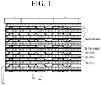
- FIG. 1 can be regarded as a section through a part of a brazed heat exchanger according to the invention.
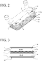
- FIG. 2 shows a perspective view of the heat exchanger from FIG. 1 .
- the plates 1 have four plate openings 12.
- FIG. 3 is a highly abstract sketch showing only two of the ducts 2a, 2b of the heat exchanger and three of the plates 1.
- the braze materials 3a, 3b are in the form of braze foils.
- the braze foils can be cut out over a large area such that the braze material 3a, 3b is present only at the contact surfaces (not shown).
- the contact surfaces are for example those marked by lines in FIGs. 4 - 6 .
- the braze material 3 a, 3b is provided in the form of plating.
- FIGs. 4 and 5 show an insert in the form of an undulating duct sheet 4b which is situated in one set of ducts 2b.
- One illustration shows the top side of the duct sheet 4b and the other illustration shows the underside thereof.
- the braze material 3b which in this case is applied as braze paste, has been indicated - not in full but predominantly - by the thick lines.
- FIG. 6 shows a detail of an insert in the form an undulating fin 4a that is situated in the other set of ducts 2a.
- the other braze material 3a which is likewise applied in the form of a braze paste, has been indicated by straight thick lines - dashed lines on the underside (not visible in FIG. 6 ) of the undulation troughs 4t and solid lines on the visible top side of the undulation peaks 4bg.
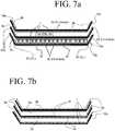
- FIG. 7a shows a further abstract sketch of a possible embodiment on the basis of a duct 2b formed from two plates 1 (still illustrated with a spacing to one another), in which duct there is situated an undulating duct sheet 4b.
- a braze material identical to the respective duct 2a, 2b. Only one of the oil ducts 2a is shown in FIG. 7a , in a somewhat more abstract fashion, above the coolant duct 2b.
- the braze on the plate edges 10 is - by contrast to that shown in FIG. 7a - identical for all of the plates 1 or for all of the ducts 2a, 2b.
- a Cu-based braze material 3a On the bent edges 10 of the plates 1 that extend around the entire plate periphery, there is provided a Cu-based braze material 3a.
- a Fe-based braze material 3b is provided on the duct sheet 4b. It is self-evident that all of the ducts 2b that are assigned, in an oil cooler, to a cooling liquid have been designed in the manner of the duct 2b that is shown.
- the Cu-based braze material 3a is provided both in the oil ducts 2a and also on the associated plate edges 10. It has been found that the relatively small amount of copper on the edges 10 does not result in copper dissolution phenomena.
- the undulating duct sheets 4b and the undulating fins 4a are, in an exemplary embodiment that is not shown, of physically identical form, for example designed as shown in FIG. 6 .
- a mix of fins 4a and duct sheets 4b is provided in the ducts 2a and/or 2b.
- the fins 4a and the duct sheets 4b which are situated jointly in one duct should be provided with an identical braze material 3a or 3b.
- a mix of fins and studs 11 it is also possible for a mix of fins and studs 11 to be provided in each duct 2a and 2b, or else a mix of duct sheets 4b and studs 11.
- braze materials 3a, 3b are provided only at the said contact surfaces, which of the surfaces on the butting protuberances.
- the contact surfaces likewise correspond to the brazed connection seams
- braze materials 3a, 3b in the form of braze paste may be realized by means of rotating drums W or by means other devices in order that said process can be carried out in an effective manner, that is to say in a manner suitable for mass production. Screen printing methods are also known and suitable for braze application. Owing to the at least two different braze materials 3a, 3b, separate production lines are expedient. Contact between the braze materials should at least be prevented.
- FIG. 8 shows a stack of heat exchanger plates 1 arranged in the housing 30.
- the plates 1 have only two plate openings 12, for example for oil.
- a flange 5 is situated on the opening 12 of the uppermost plate 1.
- the housing 30 has an inlet 31 and an outlet 32, for example for a cooling liquid CL.
- FIG. 9 shows a stack of said type on its own.
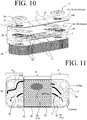
- FIG. 10 shows a stack illustrated in a partially exploded view.
- the uppermost duct 2b in the stack for the cooling liquid CL has been illustrated in exploded form.
- in uppermost duct 2a in the stack for oil has been illustrated a plate pair.
- the braze material 3b in the ducts 2b is, in this example embodiment, inserted in the form of a braze foil.
- a braze powder may be applied to the fins 4a situated therein.
- the ducts 2b are predominantly formed with studs 11 which are stamped into the plates 1. Opposite studs 11 are brazed to one another. It is sufficient here for the expensive braze material 3a or 3b to be applied only to the tips of the studs.
- FIGs. 11-13 show another exemplary embodiment using a "caseless" heat exchanger which has exclusively closed channels, similar to the embodiment of FIGs. 1-7 .
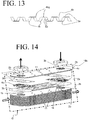
- FIG. 14 shows another exemplary embodiment using a heat exchanger in a housing which has closed and open channels, similar to the embodiment of FIGs. 8-10 .
- FIG. 11 shows a view into an uppermost channel 2a which is preferably a cooling liquid channel.
- a heat exchanger part 1 in particular a heat exchanger plate 1 with an obliquely raised edge 10a can be seen.
- the edges 10a of the plates 1 are connected in order to form the closed channels.
- Four holes are situated in said heat exchanger plates 1.
- a further heat exchanger plate 1 is laid on top in order to form the liquid channel which is shown.
- Said further heat exchanger plate (not shown) might also be a cover plate which normally has somewhat thicker walls than a heat exchanger plate 1.
- the upper left-hand and the upper right-hand hole is a part of an inlet channel and an outlet channel 14, 15, respectively.
- the channel 2b (not shown) which is adjacent toward the bottom, preferably an oil channel, is fed.
- the channels 2a and 2b alternate in the vertical plate stack direction, as is usually customary at any rate.
- the inlet and outlet channels 12, 13, 14, 15 which are formed in this way are otherwise clearly visible in FIG. 12 which shows a perspective view of the plate stack.
- the lower right-hand and the lower left-hand hole and the inlet and outlet channels 12, 13 which are formed from them in the plate stack are correspondingly provided for the cooling liquid. It can accordingly be assumed that the cooling liquid flows into the cooling liquid channel 2a which is shown at the bottom right and leaves said channel 2a again at the bottom left ( FIG. 1 ).
- each corrugated duct sheet 4a is situated in the upper liquid channel which is shown and preferably also in all other liquid channels of the heat exchanger, on the left and right in the inlet region and in the outlet region of the liquid channel.
- the corrugated duct sheets 4a have two openings, each of which corresponds with one of the abovementioned holes in the plates 1. The openings are therefore slightly larger than the holes.
- the duct sheets 4a have arcuate corrugations which firstly lead from the inlet channel to a middle plate region and secondly lead from the middle plate region to the outlet channel. To this end, apertures are arranged in the duct sheets 4a at the ends of the corrugations.
- the liquid can flow between the duct sheet 4a and the lower heat exchanger plate 1.
- the duct sheets 4a are configured without corrugations, that is to say are of planar configuration, the liquid flows between the duct sheet 4a and the upper heat exchanger plate 1.
- individual lobes 11 are also present in the corrugated duct sheets 4a.
- a corrugated fin 4b is situated between the two duct sheets 4a, the details of which corrugated fin 4b are shown in FIG. 13 .
- the corrugations of the duct sheets 4a and the fins 4b have corresponding corrugation peaks 4bg and corrugation troughs 4t.
- the fin 4b has cuts in the corrugation flanks 42.
- a copper brazing material 3b indicated in FIG.11 merely by way of some thick, arcuate lines which lie on the corrugation peaks 4bg, is situated on the visible upper side on the corrugations of the duct sheets 4a.
- the copper brazing material 3b for connecting to a bottom of the heat exchanger plate 1 which is shown is also situated on the non-visible underside of the duct sheets 4a.
- the copper brazing material 3b on the underside is situated on the planar areas which lie on the bottom of the heat exchanger plate 1 and which can also be understood to be corrugation troughs 4t.
- an iron brazing material 3a is situated on the upper side and on the underside of the fin 4b and on its corrugation peaks 4bg and corrugation troughs 4t. Said embodiment applies to the upper channel 2a which is shown and to the lower channel 2a which is not shown.
- FIGs. 11 to 13 have not shown the oil channels in detail.
- the oil channels might be provided completely with a fin 4b (shown in FIG. 3 ) or might also be of some other configuration.
- the copper brazing material 3b is situated therein in said exemplary embodiment, in order to withstand the high pressure on the oil side.
- two first part regions A have also been marked which are arranged to the left and the right of a second part region B which corresponds to the abovementioned middle plate or channel region.
- the part regions A correspond to the likewise abovementioned inlet and outlet regions.
- all the liquid channels of the heat exchanger are configured with the one and with the other brazing material 3a, 3b in the alternative embodiment.
- the copper brazing material 3b is therefore situated in the two part regions A and the iron brazing material 3a is situated in the second part region B.
- the copper brazing material 3b is also situated in all the oil channels here.
- FIG. 14 shows the oil channels there in somewhat greater detail. They are situated within tubes which are formed in this exemplary embodiment from pairs of plates 1 which are connected at their plate edges 10b and which therefore produce in each case one closed channel (first channel 2a). In contrast to the previous exemplary embodiment, said plates 1 have merely two openings. In each case one open channel (second channel 2b) is situated between the tubes.
- the housing G which is present in said exemplary embodiment and in which the stack according to FIG. 4 is situated has been indicated as a dashed-line frame, but can in general be similar to the housing 30 of FIG. 8 .
- the open channels are flowed through by a cooling liquid which enters into the housing G and leaves the housing G again after having flowed through the open channels.
- the cooling liquid has been symbolized by way of block arrows and the oil by way of line arrows in FIG. 14 .
- a copper brazing material 3b is also situated within the oil channels in said exemplary embodiment.
- two other duct sheets 4c are situated in the open channels.
- the said other duct sheets 4c have merely a single opening. They are also of corrugated configuration, however, in order that they can be flowed through just like the duct sheets 4a of the previous exemplary embodiment.
- the opening corresponds with one of the abovementioned two plate openings.
- a copper brazing material 3b is situated in the upper, open channel which is shown, whereas an iron brazing material 3a is situated in the remaining other open channels which are not shown in detail.
- the copper brazing material 3b has been shown as a brazing film, without being restricted hereto. It might also be, for example, a brazing paste or a brazing coating.
- the brazing film has been provided with cutouts, in order that the brazing material 3b is present only where it is required, for example in order to connect two lobes 11 which lie opposite one another and are configured in the plates 1, and which in each case protrude into the open channels.
- the basic material of those parts of the heat exchangers which are shown in the exemplary embodiments is a stainless steel. In other exemplary embodiments which are not shown, it can be, for example, an aluminum alloy or another metal which can be brazed with correspondingly different brazing materials.
- the heat exchangers according to the invention may, aside from being used as oil coolers, be advantageous for all possible applications, in particular for applications in which it is sought to eliminate certain metallic elements, such as in this case copper, for example.
Claims (13)
- Échangeur de chaleur brasé présentant des plaques empilées (1) définissant une pluralité de conduits afin de permettre l'écoulement de deux milieux ou plus entre les plaques, comprenant :un premier matériau de brasage (3a) fournissant des joints de brassage dans un premier ensemble de la pluralité de conduits (2a) ; etun second matériau de brasage (3b) de composition différente du premier matériau de brasage fournissant des joints de brasage dans un second ensemble de la pluralité de conduits (2b),le premier matériau de brasage et le second matériau de brasage présentant une adéquation des gammes de température de fusion, dans lequel au moins certains de la pluralité de conduits sont soit dans le premier ensemble ou dans le second ensemble mais pas dans les deux, dans lequel un du premier et du second matériau de brasage est un matériau de brasage à base de cuivre et l'autre du premier et du second matériau de brasage est un matériau de brasage à base de fer.
- Échangeur de chaleur brasé selon la revendication 1, dans lequel les plaques empilées (1) sont réalisées en acier.
- Échangeur de chaleur brasé selon la revendication 1, dans lequel aucun de la pluralité de conduits (2a, 2b) n'est à la fois dans le premier ensemble et dans le second ensemble.
- Échangeur de chaleur brasé selon la revendication 1, dans lequel des plaques adjacentes des plaques empilées (1) sont jointes le long de leur périphérie par au moins un du premier et du second matériau de brasage (3a, 3b).
- Échangeur de chaleur brasé selon la revendication 4, dans lequel des paires successives des plaques empilées (1) dans une direction d'empilement sont jointes le long de leur périphérie par le premier et le second matériau de brasage (3a, 3b) en séquence alternative.
- Échangeur de chaleur brasé selon la revendication 4, dans lequel tous les joints de brasage le long des périphéries des plaques empilées (1) sont formés par exactement un du premier et du second matériau de brasage (3a, 3b).
- Échangeur de chaleur brasé selon la revendication 1, dans lequel le premier et le second ensemble de conduits (2a, 2b) sont agencés en alternance dans une direction d'empilement des plaques empilées (1).
- Échangeur de chaleur brasé selon la revendication 1, comprenant en outre des inserts (4a, 4b) agencés dans au moins certains des conduits (2a, 2b) et joints aux plaques (1) par au moins un des premier et second matériaux de brasage (3a, 3b).
- Échangeur de chaleur brasé selon la revendication 8, dans lequel au moins certains des inserts (4b) sont des ailettes ondulées.
- Échangeur de chaleur brasé selon la revendication 8, dans lequel au moins certains des inserts (4a) sont des feuilles de conduits ondulées.
- Échangeur de chaleur brasé selon la revendication 1, dans lequel au moins certains des conduits (2a, 2b) incluent :une périphérie scellée définie par des bords d'une première des plaques et d'une seconde des plaques, lesdits bords étant joints par un des premier et second matériaux de brasage (3a, 3b) ; etun insert (4a, 4b) agencé dans ledit conduit (2a, 2b) et joint à la fois à la première des plaques et à la seconde des plaques par l'autre des premier et second matériaux de brasage (3a, 3b).
- Échangeur de chaleur brasé selon la revendication 1, dans lequel au moins certains des conduits (2a, 2b) incluent :une périphérie scellée définie par des bords d'une première des plaques et d'une seconde des plaques ;un premier insert (4a, 4b) agencé dans ledit conduit et joint à la fois à la première des plaques et à la seconde des plaques par l'un des premier et second matériaux de brasage (3a, 3b), etun second insert (4a, 4b) agencé dans ledit conduit et joint à la fois à la première des plaques et à la seconde des plaques par l'autre des premier et second matériaux de brasage (3a, 3b).
- Échangeur de chaleur brasé selon la revendication 1, dans lequel la pluralité de conduits (2a, 2b) inclut :une première pluralité de conduits (2a) pour un premier des milieux et une seconde pluralité de conduits (2b) pour un second des milieux, la première et la seconde pluralités de conduits étant agencées en alternance dans la pile de plaques (1),dans lequel toute la première pluralité de conduits appartient au premier ensemble de conduits, toute la seconde pluralité de conduits appartient au second ensemble de conduits et au moins un des plus extérieurs de la seconde pluralité de conduits appartient en outre au premier ensemble de conduits.
Applications Claiming Priority (3)
| Application Number | Priority Date | Filing Date | Title |
|---|---|---|---|
| DE102014015170.0A DE102014015170B3 (de) | 2014-10-10 | 2014-10-10 | Gelöteter Wärmetauscher und Herstellungsverfahren |
| DE102015010310.5A DE102015010310A1 (de) | 2015-08-08 | 2015-08-08 | Gelöteter Wärmetauscher und Herstellungsverfahren |
| PCT/US2015/054811 WO2016057856A1 (fr) | 2014-10-10 | 2015-10-09 | Échangeur de chaleur brasé et son procédé de fabrication |
Publications (3)
| Publication Number | Publication Date |
|---|---|
| EP3204183A1 EP3204183A1 (fr) | 2017-08-16 |
| EP3204183A4 EP3204183A4 (fr) | 2018-05-30 |
| EP3204183B1 true EP3204183B1 (fr) | 2020-05-27 |
Family
ID=55653816
Family Applications (1)
| Application Number | Title | Priority Date | Filing Date |
|---|---|---|---|
| EP15849290.0A Active EP3204183B1 (fr) | 2014-10-10 | 2015-10-09 | Échangeur de chaleur brasé |
Country Status (5)
| Country | Link |
|---|---|
| US (1) | US10302366B2 (fr) |
| EP (1) | EP3204183B1 (fr) |
| CN (1) | CN106794531B (fr) |
| CA (1) | CA2961642A1 (fr) |
| WO (1) | WO2016057856A1 (fr) |
Families Citing this family (14)
| Publication number | Priority date | Publication date | Assignee | Title |
|---|---|---|---|---|
| DE102014005149B4 (de) * | 2014-04-08 | 2016-01-21 | Modine Manufacturing Company | Gelöteter Wärmetauscher |
| DE102016007089A1 (de) * | 2016-06-10 | 2017-06-29 | Modine Manufacturing Company | Flanschplatte mit Unterkühlfunktion |
| WO2018216245A1 (fr) * | 2017-05-23 | 2018-11-29 | 三菱電機株式会社 | Échangeur de chaleur à plaques et système d'alimentation en eau chaude de pompe à chaleur |
| FR3069919B1 (fr) * | 2017-08-04 | 2019-11-22 | L'air Liquide, Societe Anonyme Pour L'etude Et L'exploitation Des Procedes Georges Claude | Element intercalaire en alliage d'aluminium de fonderie pour un echangeur de chaleur |
| US11719495B2 (en) * | 2018-03-15 | 2023-08-08 | Mitsubishi Electric Corporation | Plate heat exchanger, heat pump device including plate heat exchanger, and heat pump type of cooling, heating, and hot water supply system including heat pump device |
| DE102018006461B4 (de) * | 2018-08-10 | 2024-01-25 | Eberhard Paul | Wärmetauscher mit ineinanderragenden spitzwinkligen oder spitzdachartigen Platinen |
| US10801789B2 (en) * | 2019-02-05 | 2020-10-13 | Senior Uk Limited | Heat exchangers with improved fluid distribution |
| CN109732165A (zh) * | 2019-02-22 | 2019-05-10 | 常州爱克普换热器有限公司 | 换热器翅板真空钎焊工艺 |
| CN113474610B (zh) * | 2019-02-25 | 2023-09-15 | 乔治洛德方法研究和开发液化空气有限公司 | 集成至少一种热交换功能和一种蒸馏功能的基体 |
| SE543338C2 (en) * | 2019-04-04 | 2020-12-08 | Swep Int Ab | Stencil device and method for stencil printing of brazing material onto a heat exchanger plate and use thereof |
| CN110253131B (zh) * | 2019-07-01 | 2020-12-04 | 中国科学院工程热物理研究所 | 毛细通道换热器及其制备方法 |
| US11217505B2 (en) * | 2019-09-10 | 2022-01-04 | Aptiv Technologies Limited | Heat exchanger for electronics |
| US11633799B2 (en) * | 2020-10-01 | 2023-04-25 | Hamilton Sundstrand Corporation | Control assembly fabrication via brazing |
| CN112809117A (zh) * | 2021-03-02 | 2021-05-18 | 辽宁东升精机有限公司 | 封条式散热器芯体封条钎焊工艺 |
Family Cites Families (34)
| Publication number | Priority date | Publication date | Assignee | Title |
|---|---|---|---|---|
| FR2303622A1 (fr) * | 1975-03-10 | 1976-10-08 | Microturbo Sa | Procede de fabrication d'une unite du type echangeur de chaleur |
| JPS5639908Y2 (fr) | 1977-04-23 | 1981-09-17 | ||
| US4327802A (en) * | 1979-06-18 | 1982-05-04 | Borg-Warner Corporation | Multiple fluid heat exchanger |
| DE3107010C2 (de) * | 1981-02-25 | 1985-02-28 | Dieter Christian Steinegg-Appenzell Steeb | Metallkühler zum Kühlen eines unter hohem Druck durchströmenden Fluids durch Luft |
| US4967835A (en) * | 1989-08-21 | 1990-11-06 | Modine Manufacturing Company, Inc. | Filter first donut oil cooler |
| US5102032A (en) | 1989-09-12 | 1992-04-07 | Modine Manufacturing Company | Finned assembly for heat exchangers |
| US5042574A (en) | 1989-09-12 | 1991-08-27 | Modine Manufacturing Company | Finned assembly for heat exchangers |
| US4949543A (en) | 1989-09-12 | 1990-08-21 | Modine Manufacturing Company | Tube and fin assembly for heat exchangers in power plants |
| FR2656412B1 (fr) * | 1989-12-21 | 1995-02-17 | Valeo Thermique Moteur Sa | Echangeur de chaleur a lames, en particulier pour le refroidissement de l'huile de lubrification d'un vehicule automobile. |
| DE19511991C2 (de) * | 1995-03-31 | 2002-06-13 | Behr Gmbh & Co | Plattenwärmetauscher |
| US20010047862A1 (en) | 1995-04-13 | 2001-12-06 | Anderson Alexander F. | Carbon/carbon heat exchanger and manufacturing method |
| US5595271A (en) | 1995-08-07 | 1997-01-21 | Tseng; Ling-Yuan | Electric vehicle pick-up position control |
| CA2260890A1 (fr) * | 1999-02-05 | 2000-08-05 | Long Manufacturing Ltd. | Echangeurs de chaleur fermes |
| JP2001116483A (ja) * | 1999-10-22 | 2001-04-27 | Ebara Corp | プレート熱交換器 |
| US6544662B2 (en) | 1999-10-25 | 2003-04-08 | Alliedsignal Inc. | Process for manufacturing of brazed multi-channeled structures |
| JP2002028775A (ja) | 2000-05-10 | 2002-01-29 | Denso Corp | 耐腐食性熱交換器の製造方法 |
| JP3448265B2 (ja) | 2000-07-27 | 2003-09-22 | 昭 藤山 | チタン製プレート式熱交換器の製造方法 |
| JP2002137054A (ja) * | 2000-10-26 | 2002-05-14 | Toyo Radiator Co Ltd | 熱交換器の製造方法および熱交換器 |
| FR2816046B1 (fr) | 2000-10-27 | 2003-01-24 | Air Liquide | Procede de fabrication d'un echangeur de chaleur a plaques brasees, et echangeur ainsi produit |
| JP2002168591A (ja) * | 2000-11-29 | 2002-06-14 | Denso Corp | アルミニウム製熱交換器 |
| SE519062C2 (sv) | 2001-05-03 | 2003-01-07 | Alfa Laval Corp Ab | Sätt att sammanlöda tunna värmeväxlarplattor samt lödd plattvärmeväxlare framställd enligt sättet |
| DE10349141A1 (de) * | 2003-10-17 | 2005-05-12 | Behr Gmbh & Co Kg | Stapelscheibenwärmeübertrager, insbesondere Ölkühler für Kraftfahrzeuge |
| DE10353577A1 (de) | 2003-11-14 | 2005-06-16 | Behr Gmbh & Co. Kg | Hochtemperaturgelöteter Abgaswärmetauscher |
| WO2005061166A1 (fr) * | 2003-12-24 | 2005-07-07 | Showa Denko K.K. | Echangeur thermique et son procede de fabrication |
| US20070017561A1 (en) * | 2005-07-19 | 2007-01-25 | Shih-Shin Kuo | Automatic collapsible umbrella |
| EP1913324B1 (fr) * | 2005-07-19 | 2011-09-14 | Behr GmbH & Co. KG | Echangeur thermique |
| DE102005053924B4 (de) * | 2005-11-11 | 2016-03-31 | Modine Manufacturing Co. | Ladeluftkühler in Plattenbauweise |
| JP4675821B2 (ja) | 2006-04-28 | 2011-04-27 | 株式会社豊田中央研究所 | ろう付け方法 |
| JP4270237B2 (ja) * | 2006-07-31 | 2009-05-27 | 日立電線株式会社 | 非ハロゲン難燃性熱可塑性エラストマー組成物及びその製造方法並びにこれを用いた電線・ケーブル |
| US20080078538A1 (en) * | 2006-09-28 | 2008-04-03 | Ali Jalilevand | Heat exchanger plate having integrated turbulation feature |
| DE102006048305B4 (de) * | 2006-10-12 | 2011-06-16 | Modine Manufacturing Co., Racine | Plattenwärmetauscher |
| JP5196940B2 (ja) | 2007-10-02 | 2013-05-15 | 三菱化学株式会社 | ケーキ類製造用澱粉組成物およびケーキ類 |
| HUE028006T2 (en) * | 2011-11-11 | 2016-11-28 | Aleris Rolled Prod Germany Gmbh | Aluminum alloy plate product or extruded product for brazing without fluid |
| EP2746711A1 (fr) | 2012-12-21 | 2014-06-25 | VALEO AUTOSYSTEMY Sp. Z. o.o. | Plaque de noyau d'échangeur de chaleur, échangeur de chaleur équipé d'une telle plaque et procédé de fabrication d'un tel échangeur de chaleur |
-
2015
- 2015-10-09 EP EP15849290.0A patent/EP3204183B1/fr active Active
- 2015-10-09 CN CN201580054414.5A patent/CN106794531B/zh active Active
- 2015-10-09 WO PCT/US2015/054811 patent/WO2016057856A1/fr active Application Filing
- 2015-10-09 CA CA2961642A patent/CA2961642A1/fr not_active Abandoned
- 2015-10-09 US US15/517,661 patent/US10302366B2/en active Active
Non-Patent Citations (1)
| Title |
|---|
| None * |
Also Published As
| Publication number | Publication date |
|---|---|
| EP3204183A4 (fr) | 2018-05-30 |
| CN106794531A (zh) | 2017-05-31 |
| CN106794531B (zh) | 2019-06-07 |
| WO2016057856A1 (fr) | 2016-04-14 |
| US20170241716A1 (en) | 2017-08-24 |
| CA2961642A1 (fr) | 2016-04-14 |
| EP3204183A1 (fr) | 2017-08-16 |
| US10302366B2 (en) | 2019-05-28 |
Similar Documents
| Publication | Publication Date | Title |
|---|---|---|
| EP3204183B1 (fr) | Échangeur de chaleur brasé | |
| US20170038150A1 (en) | Brazed Heat Exchanger and Production Method | |
| US6959492B1 (en) | Plate type heat exchanger and method of manufacturing the heat exchanger | |
| US20150285572A1 (en) | Brazed heat exchanger | |
| JP5226015B2 (ja) | プレート熱交換器 | |
| US10462931B2 (en) | Heat exchanger | |
| KR100677719B1 (ko) | 납땜방법 및 납땜구조 | |
| JP5601928B2 (ja) | 高密度積層型熱交換器 | |
| EP1094291A2 (fr) | Echangeur de chaleur à plaques | |
| EP3086072A1 (fr) | Échangeur de chaleur sans plaque à collecteur | |
| JP4482997B2 (ja) | 積層式熱交換器およびその製造方法 | |
| EP1750078A2 (fr) | Echangeur de chaleur en alliages de cuivre et laiton avec recuit à haute température et facteur de dureté élevé, capable de résister aux pressions internes élevées | |
| EP4343263A1 (fr) | Module d'échangeur de chaleur | |
| EP4023992A1 (fr) | Échangeur de chaleur | |
| CN215337881U (zh) | 换热器 | |
| US11340027B2 (en) | Tube for a heat exchanger, and method of making the same | |
| JP2000039284A5 (fr) | ||
| TW493059B (en) | Plate heat exchanger and method of making same | |
| EP4343252A1 (fr) | Echangeur de chaleur à plaques | |
| WO2020232261A1 (fr) | Échangeur de chaleur à plaques | |
| JP2002267272A (ja) | 熱交換器 | |
| JP2019035528A (ja) | 熱交換器 | |
| JP2011185498A (ja) | 熱交換器 |
Legal Events
| Date | Code | Title | Description |
|---|---|---|---|
| STAA | Information on the status of an ep patent application or granted ep patent |
Free format text: STATUS: THE INTERNATIONAL PUBLICATION HAS BEEN MADE |
|
| PUAI | Public reference made under article 153(3) epc to a published international application that has entered the european phase |
Free format text: ORIGINAL CODE: 0009012 |
|
| STAA | Information on the status of an ep patent application or granted ep patent |
Free format text: STATUS: REQUEST FOR EXAMINATION WAS MADE |
|
| 17P | Request for examination filed |
Effective date: 20170510 |
|
| AK | Designated contracting states |
Kind code of ref document: A1 Designated state(s): AL AT BE BG CH CY CZ DE DK EE ES FI FR GB GR HR HU IE IS IT LI LT LU LV MC MK MT NL NO PL PT RO RS SE SI SK SM TR |
|
| AX | Request for extension of the european patent |
Extension state: BA ME |
|
| DAV | Request for validation of the european patent (deleted) | ||
| DAX | Request for extension of the european patent (deleted) | ||
| A4 | Supplementary search report drawn up and despatched |
Effective date: 20180426 |
|
| RIC1 | Information provided on ipc code assigned before grant |
Ipc: F28F 1/12 20060101ALI20180420BHEP Ipc: B23K 35/30 20060101ALI20180420BHEP Ipc: F28F 3/08 20060101ALI20180420BHEP Ipc: F28D 7/16 20060101ALI20180420BHEP Ipc: B23K 1/00 20060101AFI20180420BHEP Ipc: B23K 35/02 20060101ALI20180420BHEP Ipc: F28F 3/10 20060101ALI20180420BHEP Ipc: F28F 1/02 20060101ALI20180420BHEP Ipc: F28D 21/00 20060101ALI20180420BHEP Ipc: F28F 21/06 20060101ALI20180420BHEP Ipc: F28F 21/08 20060101ALI20180420BHEP Ipc: F28D 9/00 20060101ALI20180420BHEP Ipc: F28F 9/02 20060101ALI20180420BHEP |
|
| GRAP | Despatch of communication of intention to grant a patent |
Free format text: ORIGINAL CODE: EPIDOSNIGR1 |
|
| STAA | Information on the status of an ep patent application or granted ep patent |
Free format text: STATUS: GRANT OF PATENT IS INTENDED |
|
| INTG | Intention to grant announced |
Effective date: 20191210 |
|
| GRAS | Grant fee paid |
Free format text: ORIGINAL CODE: EPIDOSNIGR3 |
|
| GRAA | (expected) grant |
Free format text: ORIGINAL CODE: 0009210 |
|
| STAA | Information on the status of an ep patent application or granted ep patent |
Free format text: STATUS: THE PATENT HAS BEEN GRANTED |
|
| AK | Designated contracting states |
Kind code of ref document: B1 Designated state(s): AL AT BE BG CH CY CZ DE DK EE ES FI FR GB GR HR HU IE IS IT LI LT LU LV MC MK MT NL NO PL PT RO RS SE SI SK SM TR |
|
| REG | Reference to a national code |
Ref country code: GB Ref legal event code: FG4D |
|
| REG | Reference to a national code |
Ref country code: CH Ref legal event code: EP |
|
| REG | Reference to a national code |
Ref country code: DE Ref legal event code: R096 Ref document number: 602015053547 Country of ref document: DE |
|
| REG | Reference to a national code |
Ref country code: AT Ref legal event code: REF Ref document number: 1274058 Country of ref document: AT Kind code of ref document: T Effective date: 20200615 |
|
| REG | Reference to a national code |
Ref country code: LT Ref legal event code: MG4D |
|
| PG25 | Lapsed in a contracting state [announced via postgrant information from national office to epo] |
Ref country code: PT Free format text: LAPSE BECAUSE OF FAILURE TO SUBMIT A TRANSLATION OF THE DESCRIPTION OR TO PAY THE FEE WITHIN THE PRESCRIBED TIME-LIMIT Effective date: 20200928 Ref country code: NO Free format text: LAPSE BECAUSE OF FAILURE TO SUBMIT A TRANSLATION OF THE DESCRIPTION OR TO PAY THE FEE WITHIN THE PRESCRIBED TIME-LIMIT Effective date: 20200827 Ref country code: GR Free format text: LAPSE BECAUSE OF FAILURE TO SUBMIT A TRANSLATION OF THE DESCRIPTION OR TO PAY THE FEE WITHIN THE PRESCRIBED TIME-LIMIT Effective date: 20200828 Ref country code: IS Free format text: LAPSE BECAUSE OF FAILURE TO SUBMIT A TRANSLATION OF THE DESCRIPTION OR TO PAY THE FEE WITHIN THE PRESCRIBED TIME-LIMIT Effective date: 20200927 Ref country code: SE Free format text: LAPSE BECAUSE OF FAILURE TO SUBMIT A TRANSLATION OF THE DESCRIPTION OR TO PAY THE FEE WITHIN THE PRESCRIBED TIME-LIMIT Effective date: 20200527 Ref country code: LT Free format text: LAPSE BECAUSE OF FAILURE TO SUBMIT A TRANSLATION OF THE DESCRIPTION OR TO PAY THE FEE WITHIN THE PRESCRIBED TIME-LIMIT Effective date: 20200527 Ref country code: FI Free format text: LAPSE BECAUSE OF FAILURE TO SUBMIT A TRANSLATION OF THE DESCRIPTION OR TO PAY THE FEE WITHIN THE PRESCRIBED TIME-LIMIT Effective date: 20200527 |
|
| REG | Reference to a national code |
Ref country code: NL Ref legal event code: MP Effective date: 20200527 |
|
| PG25 | Lapsed in a contracting state [announced via postgrant information from national office to epo] |
Ref country code: BG Free format text: LAPSE BECAUSE OF FAILURE TO SUBMIT A TRANSLATION OF THE DESCRIPTION OR TO PAY THE FEE WITHIN THE PRESCRIBED TIME-LIMIT Effective date: 20200827 Ref country code: LV Free format text: LAPSE BECAUSE OF FAILURE TO SUBMIT A TRANSLATION OF THE DESCRIPTION OR TO PAY THE FEE WITHIN THE PRESCRIBED TIME-LIMIT Effective date: 20200527 Ref country code: HR Free format text: LAPSE BECAUSE OF FAILURE TO SUBMIT A TRANSLATION OF THE DESCRIPTION OR TO PAY THE FEE WITHIN THE PRESCRIBED TIME-LIMIT Effective date: 20200527 Ref country code: RS Free format text: LAPSE BECAUSE OF FAILURE TO SUBMIT A TRANSLATION OF THE DESCRIPTION OR TO PAY THE FEE WITHIN THE PRESCRIBED TIME-LIMIT Effective date: 20200527 |
|
| REG | Reference to a national code |
Ref country code: AT Ref legal event code: MK05 Ref document number: 1274058 Country of ref document: AT Kind code of ref document: T Effective date: 20200527 |
|
| PG25 | Lapsed in a contracting state [announced via postgrant information from national office to epo] |
Ref country code: NL Free format text: LAPSE BECAUSE OF FAILURE TO SUBMIT A TRANSLATION OF THE DESCRIPTION OR TO PAY THE FEE WITHIN THE PRESCRIBED TIME-LIMIT Effective date: 20200527 Ref country code: AL Free format text: LAPSE BECAUSE OF FAILURE TO SUBMIT A TRANSLATION OF THE DESCRIPTION OR TO PAY THE FEE WITHIN THE PRESCRIBED TIME-LIMIT Effective date: 20200527 |
|
| PG25 | Lapsed in a contracting state [announced via postgrant information from national office to epo] |
Ref country code: SM Free format text: LAPSE BECAUSE OF FAILURE TO SUBMIT A TRANSLATION OF THE DESCRIPTION OR TO PAY THE FEE WITHIN THE PRESCRIBED TIME-LIMIT Effective date: 20200527 Ref country code: EE Free format text: LAPSE BECAUSE OF FAILURE TO SUBMIT A TRANSLATION OF THE DESCRIPTION OR TO PAY THE FEE WITHIN THE PRESCRIBED TIME-LIMIT Effective date: 20200527 Ref country code: DK Free format text: LAPSE BECAUSE OF FAILURE TO SUBMIT A TRANSLATION OF THE DESCRIPTION OR TO PAY THE FEE WITHIN THE PRESCRIBED TIME-LIMIT Effective date: 20200527 Ref country code: AT Free format text: LAPSE BECAUSE OF FAILURE TO SUBMIT A TRANSLATION OF THE DESCRIPTION OR TO PAY THE FEE WITHIN THE PRESCRIBED TIME-LIMIT Effective date: 20200527 Ref country code: IT Free format text: LAPSE BECAUSE OF FAILURE TO SUBMIT A TRANSLATION OF THE DESCRIPTION OR TO PAY THE FEE WITHIN THE PRESCRIBED TIME-LIMIT Effective date: 20200527 Ref country code: RO Free format text: LAPSE BECAUSE OF FAILURE TO SUBMIT A TRANSLATION OF THE DESCRIPTION OR TO PAY THE FEE WITHIN THE PRESCRIBED TIME-LIMIT Effective date: 20200527 Ref country code: ES Free format text: LAPSE BECAUSE OF FAILURE TO SUBMIT A TRANSLATION OF THE DESCRIPTION OR TO PAY THE FEE WITHIN THE PRESCRIBED TIME-LIMIT Effective date: 20200527 Ref country code: CZ Free format text: LAPSE BECAUSE OF FAILURE TO SUBMIT A TRANSLATION OF THE DESCRIPTION OR TO PAY THE FEE WITHIN THE PRESCRIBED TIME-LIMIT Effective date: 20200527 |
|
| PG25 | Lapsed in a contracting state [announced via postgrant information from national office to epo] |
Ref country code: PL Free format text: LAPSE BECAUSE OF FAILURE TO SUBMIT A TRANSLATION OF THE DESCRIPTION OR TO PAY THE FEE WITHIN THE PRESCRIBED TIME-LIMIT Effective date: 20200527 Ref country code: SK Free format text: LAPSE BECAUSE OF FAILURE TO SUBMIT A TRANSLATION OF THE DESCRIPTION OR TO PAY THE FEE WITHIN THE PRESCRIBED TIME-LIMIT Effective date: 20200527 |
|
| REG | Reference to a national code |
Ref country code: DE Ref legal event code: R097 Ref document number: 602015053547 Country of ref document: DE |
|
| PLBE | No opposition filed within time limit |
Free format text: ORIGINAL CODE: 0009261 |
|
| STAA | Information on the status of an ep patent application or granted ep patent |
Free format text: STATUS: NO OPPOSITION FILED WITHIN TIME LIMIT |
|
| REG | Reference to a national code |
Ref country code: DE Ref legal event code: R119 Ref document number: 602015053547 Country of ref document: DE |
|
| 26N | No opposition filed |
Effective date: 20210302 |
|
| PG25 | Lapsed in a contracting state [announced via postgrant information from national office to epo] |
Ref country code: SI Free format text: LAPSE BECAUSE OF FAILURE TO SUBMIT A TRANSLATION OF THE DESCRIPTION OR TO PAY THE FEE WITHIN THE PRESCRIBED TIME-LIMIT Effective date: 20200527 |
|
| REG | Reference to a national code |
Ref country code: CH Ref legal event code: PL |
|
| GBPC | Gb: european patent ceased through non-payment of renewal fee |
Effective date: 20201009 |
|
| PG25 | Lapsed in a contracting state [announced via postgrant information from national office to epo] |
Ref country code: MC Free format text: LAPSE BECAUSE OF FAILURE TO SUBMIT A TRANSLATION OF THE DESCRIPTION OR TO PAY THE FEE WITHIN THE PRESCRIBED TIME-LIMIT Effective date: 20200527 Ref country code: LU Free format text: LAPSE BECAUSE OF NON-PAYMENT OF DUE FEES Effective date: 20201009 |
|
| REG | Reference to a national code |
Ref country code: BE Ref legal event code: MM Effective date: 20201031 |
|
| PG25 | Lapsed in a contracting state [announced via postgrant information from national office to epo] |
Ref country code: DE Free format text: LAPSE BECAUSE OF NON-PAYMENT OF DUE FEES Effective date: 20210501 Ref country code: FR Free format text: LAPSE BECAUSE OF NON-PAYMENT OF DUE FEES Effective date: 20201031 |
|
| PG25 | Lapsed in a contracting state [announced via postgrant information from national office to epo] |
Ref country code: LI Free format text: LAPSE BECAUSE OF NON-PAYMENT OF DUE FEES Effective date: 20201031 Ref country code: GB Free format text: LAPSE BECAUSE OF NON-PAYMENT OF DUE FEES Effective date: 20201009 Ref country code: BE Free format text: LAPSE BECAUSE OF NON-PAYMENT OF DUE FEES Effective date: 20201031 Ref country code: CH Free format text: LAPSE BECAUSE OF NON-PAYMENT OF DUE FEES Effective date: 20201031 |
|
| REG | Reference to a national code |
Ref country code: GB Ref legal event code: S28 Free format text: APPLICATION FILED |
|
| PG25 | Lapsed in a contracting state [announced via postgrant information from national office to epo] |
Ref country code: IE Free format text: LAPSE BECAUSE OF NON-PAYMENT OF DUE FEES Effective date: 20201009 |
|
| REG | Reference to a national code |
Ref country code: DE Ref legal event code: R073 Ref document number: 602015053547 Country of ref document: DE |
|
| REG | Reference to a national code |
Ref country code: DE Ref legal event code: R074 Ref document number: 602015053547 Country of ref document: DE |
|
| REG | Reference to a national code |
Ref country code: GB Ref legal event code: S28 Free format text: RESTORATION ALLOWED Effective date: 20211122 |
|
| PG25 | Lapsed in a contracting state [announced via postgrant information from national office to epo] |
Ref country code: FR Free format text: LAPSE BECAUSE OF NON-PAYMENT OF DUE FEES Effective date: 20201031 Ref country code: DE Free format text: LAPSE BECAUSE OF NON-PAYMENT OF DUE FEES Effective date: 20210501 |
|
| PGRI | Patent reinstated in contracting state [announced from national office to epo] |
Ref country code: FR Effective date: 20211224 Ref country code: DE Effective date: 20211113 |
|
| PG25 | Lapsed in a contracting state [announced via postgrant information from national office to epo] |
Ref country code: TR Free format text: LAPSE BECAUSE OF FAILURE TO SUBMIT A TRANSLATION OF THE DESCRIPTION OR TO PAY THE FEE WITHIN THE PRESCRIBED TIME-LIMIT Effective date: 20200527 Ref country code: MT Free format text: LAPSE BECAUSE OF FAILURE TO SUBMIT A TRANSLATION OF THE DESCRIPTION OR TO PAY THE FEE WITHIN THE PRESCRIBED TIME-LIMIT Effective date: 20200527 Ref country code: CY Free format text: LAPSE BECAUSE OF FAILURE TO SUBMIT A TRANSLATION OF THE DESCRIPTION OR TO PAY THE FEE WITHIN THE PRESCRIBED TIME-LIMIT Effective date: 20200527 |
|
| PG25 | Lapsed in a contracting state [announced via postgrant information from national office to epo] |
Ref country code: MK Free format text: LAPSE BECAUSE OF FAILURE TO SUBMIT A TRANSLATION OF THE DESCRIPTION OR TO PAY THE FEE WITHIN THE PRESCRIBED TIME-LIMIT Effective date: 20200527 |
|
| PGFP | Annual fee paid to national office [announced via postgrant information from national office to epo] |
Ref country code: GB Payment date: 20231027 Year of fee payment: 9 |
|
| REG | Reference to a national code |
Ref country code: DE Ref legal event code: R082 Ref document number: 602015053547 Country of ref document: DE Representative=s name: TER MEER STEINMEISTER & PARTNER PATENTANWAELTE, DE |
|
| PGFP | Annual fee paid to national office [announced via postgrant information from national office to epo] |
Ref country code: FR Payment date: 20231025 Year of fee payment: 9 Ref country code: DE Payment date: 20231027 Year of fee payment: 9 |