EP3203650A1 - Système de radiocommunication, appareil de station de base radio et équipement utilisateur - Google Patents
Système de radiocommunication, appareil de station de base radio et équipement utilisateur Download PDFInfo
- Publication number
- EP3203650A1 EP3203650A1 EP17162534.6A EP17162534A EP3203650A1 EP 3203650 A1 EP3203650 A1 EP 3203650A1 EP 17162534 A EP17162534 A EP 17162534A EP 3203650 A1 EP3203650 A1 EP 3203650A1
- Authority
- EP
- European Patent Office
- Prior art keywords
- base station
- radio base
- user equipment
- antenna
- phase rotation
- Prior art date
- Legal status (The legal status is an assumption and is not a legal conclusion. Google has not performed a legal analysis and makes no representation as to the accuracy of the status listed.)
- Ceased
Links
Images


Classifications
-
- H—ELECTRICITY
- H04—ELECTRIC COMMUNICATION TECHNIQUE
- H04L—TRANSMISSION OF DIGITAL INFORMATION, e.g. TELEGRAPHIC COMMUNICATION
- H04L25/00—Baseband systems
- H04L25/02—Details ; arrangements for supplying electrical power along data transmission lines
- H04L25/0202—Channel estimation
-
- H—ELECTRICITY
- H04—ELECTRIC COMMUNICATION TECHNIQUE
- H04B—TRANSMISSION
- H04B17/00—Monitoring; Testing
- H04B17/30—Monitoring; Testing of propagation channels
- H04B17/391—Modelling the propagation channel
-
- H—ELECTRICITY
- H04—ELECTRIC COMMUNICATION TECHNIQUE
- H04B—TRANSMISSION
- H04B7/00—Radio transmission systems, i.e. using radiation field
- H04B7/02—Diversity systems; Multi-antenna system, i.e. transmission or reception using multiple antennas
- H04B7/04—Diversity systems; Multi-antenna system, i.e. transmission or reception using multiple antennas using two or more spaced independent antennas
- H04B7/0413—MIMO systems
- H04B7/0456—Selection of precoding matrices or codebooks, e.g. using matrices antenna weighting
- H04B7/046—Selection of precoding matrices or codebooks, e.g. using matrices antenna weighting taking physical layer constraints into account
- H04B7/0469—Selection of precoding matrices or codebooks, e.g. using matrices antenna weighting taking physical layer constraints into account taking special antenna structures, e.g. cross polarized antennas into account
-
- H—ELECTRICITY
- H04—ELECTRIC COMMUNICATION TECHNIQUE
- H04B—TRANSMISSION
- H04B7/00—Radio transmission systems, i.e. using radiation field
- H04B7/02—Diversity systems; Multi-antenna system, i.e. transmission or reception using multiple antennas
- H04B7/04—Diversity systems; Multi-antenna system, i.e. transmission or reception using multiple antennas using two or more spaced independent antennas
- H04B7/0413—MIMO systems
- H04B7/0456—Selection of precoding matrices or codebooks, e.g. using matrices antenna weighting
- H04B7/0478—Special codebook structures directed to feedback optimisation
- H04B7/0479—Special codebook structures directed to feedback optimisation for multi-dimensional arrays, e.g. horizontal or vertical pre-distortion matrix index [PMI]
-
- H—ELECTRICITY
- H04—ELECTRIC COMMUNICATION TECHNIQUE
- H04B—TRANSMISSION
- H04B7/00—Radio transmission systems, i.e. using radiation field
- H04B7/02—Diversity systems; Multi-antenna system, i.e. transmission or reception using multiple antennas
- H04B7/04—Diversity systems; Multi-antenna system, i.e. transmission or reception using multiple antennas using two or more spaced independent antennas
- H04B7/06—Diversity systems; Multi-antenna system, i.e. transmission or reception using multiple antennas using two or more spaced independent antennas at the transmitting station
- H04B7/0613—Diversity systems; Multi-antenna system, i.e. transmission or reception using multiple antennas using two or more spaced independent antennas at the transmitting station using simultaneous transmission
- H04B7/0615—Diversity systems; Multi-antenna system, i.e. transmission or reception using multiple antennas using two or more spaced independent antennas at the transmitting station using simultaneous transmission of weighted versions of same signal
- H04B7/0619—Diversity systems; Multi-antenna system, i.e. transmission or reception using multiple antennas using two or more spaced independent antennas at the transmitting station using simultaneous transmission of weighted versions of same signal using feedback from receiving side
- H04B7/0621—Feedback content
- H04B7/0626—Channel coefficients, e.g. channel state information [CSI]
-
- H—ELECTRICITY
- H04—ELECTRIC COMMUNICATION TECHNIQUE
- H04B—TRANSMISSION
- H04B7/00—Radio transmission systems, i.e. using radiation field
- H04B7/02—Diversity systems; Multi-antenna system, i.e. transmission or reception using multiple antennas
- H04B7/04—Diversity systems; Multi-antenna system, i.e. transmission or reception using multiple antennas using two or more spaced independent antennas
- H04B7/06—Diversity systems; Multi-antenna system, i.e. transmission or reception using multiple antennas using two or more spaced independent antennas at the transmitting station
- H04B7/0613—Diversity systems; Multi-antenna system, i.e. transmission or reception using multiple antennas using two or more spaced independent antennas at the transmitting station using simultaneous transmission
- H04B7/0615—Diversity systems; Multi-antenna system, i.e. transmission or reception using multiple antennas using two or more spaced independent antennas at the transmitting station using simultaneous transmission of weighted versions of same signal
- H04B7/0619—Diversity systems; Multi-antenna system, i.e. transmission or reception using multiple antennas using two or more spaced independent antennas at the transmitting station using simultaneous transmission of weighted versions of same signal using feedback from receiving side
- H04B7/0621—Feedback content
- H04B7/063—Parameters other than those covered in groups H04B7/0623 - H04B7/0634, e.g. channel matrix rank or transmit mode selection
-
- H—ELECTRICITY
- H04—ELECTRIC COMMUNICATION TECHNIQUE
- H04B—TRANSMISSION
- H04B7/00—Radio transmission systems, i.e. using radiation field
- H04B7/02—Diversity systems; Multi-antenna system, i.e. transmission or reception using multiple antennas
- H04B7/04—Diversity systems; Multi-antenna system, i.e. transmission or reception using multiple antennas using two or more spaced independent antennas
- H04B7/06—Diversity systems; Multi-antenna system, i.e. transmission or reception using multiple antennas using two or more spaced independent antennas at the transmitting station
- H04B7/0613—Diversity systems; Multi-antenna system, i.e. transmission or reception using multiple antennas using two or more spaced independent antennas at the transmitting station using simultaneous transmission
- H04B7/0615—Diversity systems; Multi-antenna system, i.e. transmission or reception using multiple antennas using two or more spaced independent antennas at the transmitting station using simultaneous transmission of weighted versions of same signal
- H04B7/0619—Diversity systems; Multi-antenna system, i.e. transmission or reception using multiple antennas using two or more spaced independent antennas at the transmitting station using simultaneous transmission of weighted versions of same signal using feedback from receiving side
- H04B7/0636—Feedback format
- H04B7/0645—Variable feedback
- H04B7/065—Variable contents, e.g. long-term or short-short
-
- H—ELECTRICITY
- H04—ELECTRIC COMMUNICATION TECHNIQUE
- H04L—TRANSMISSION OF DIGITAL INFORMATION, e.g. TELEGRAPHIC COMMUNICATION
- H04L5/00—Arrangements affording multiple use of the transmission path
- H04L5/003—Arrangements for allocating sub-channels of the transmission path
- H04L5/0053—Allocation of signaling, i.e. of overhead other than pilot signals
-
- H—ELECTRICITY
- H04—ELECTRIC COMMUNICATION TECHNIQUE
- H04W—WIRELESS COMMUNICATION NETWORKS
- H04W72/00—Local resource management
- H04W72/04—Wireless resource allocation
-
- H—ELECTRICITY
- H04—ELECTRIC COMMUNICATION TECHNIQUE
- H04B—TRANSMISSION
- H04B7/00—Radio transmission systems, i.e. using radiation field
- H04B7/02—Diversity systems; Multi-antenna system, i.e. transmission or reception using multiple antennas
- H04B7/04—Diversity systems; Multi-antenna system, i.e. transmission or reception using multiple antennas using two or more spaced independent antennas
- H04B7/06—Diversity systems; Multi-antenna system, i.e. transmission or reception using multiple antennas using two or more spaced independent antennas at the transmitting station
- H04B7/0613—Diversity systems; Multi-antenna system, i.e. transmission or reception using multiple antennas using two or more spaced independent antennas at the transmitting station using simultaneous transmission
- H04B7/0615—Diversity systems; Multi-antenna system, i.e. transmission or reception using multiple antennas using two or more spaced independent antennas at the transmitting station using simultaneous transmission of weighted versions of same signal
- H04B7/0619—Diversity systems; Multi-antenna system, i.e. transmission or reception using multiple antennas using two or more spaced independent antennas at the transmitting station using simultaneous transmission of weighted versions of same signal using feedback from receiving side
- H04B7/0636—Feedback format
- H04B7/0641—Differential feedback
-
- H—ELECTRICITY
- H04—ELECTRIC COMMUNICATION TECHNIQUE
- H04B—TRANSMISSION
- H04B7/00—Radio transmission systems, i.e. using radiation field
- H04B7/02—Diversity systems; Multi-antenna system, i.e. transmission or reception using multiple antennas
- H04B7/10—Polarisation diversity; Directional diversity
Definitions
- the present invention relates to a radio communication technology, and more particularly, to a three-dimensional multiple input, multiple output (3D-MIMO) radio communication system, a radio base station apparatus, and user equipment.
- 3D-MIMO three-dimensional multiple input, multiple output
- 3GPP LTE Long term evolution standardization in Third Generation Partnership Project
- Release 8 to Release 11 have adopted horizontal beamforming using linear array antenna elements arranged in the lateral dimension.
- 3D-MIMO beamforming scheme that uses a number of antenna elements arranged two-dimensionally in the vertical and the lateral directions is being discussed.
- This new technology allows a base station to perform vertical beamforming in addition to horizontal beamforming. See, for example, non-Patent documents 1 and 2 listed below. By providing directionality in both the vertical (or elevation) and the horizontal (or azimuth) directions, improvement of system characteristics is expected.
- closed loop MIMO precoding has been achieved by returning channel state information (CSI) in the horizontal direction and between polarized antenna elements back to a MIMO base station.
- CSI channel state information
- a codebook describing a set of precoding matrices is shared between the base station and user equipment.
- the user equipment selects a desired precoding matrix from the codebook and reports the selected matrix index together with the channel quality indicator (CQI) to the base station.
- the base station applies the precoding matrix to transmission data based upon the feedback information supplied from the user equipment.
- the transmission side needs to acquire channel information in the vertical direction (which may be referred to as “horizontal channel information), in addition to channel information in the horizontal direction (which may be referred to as “vertical channel information”) and channel information between polarized antenna elements (which may be referred to as “inter-polarization channel information”).
- horizontal channel information channel information in the vertical direction
- vertical channel information channel information in the horizontal direction
- inter-polarization channel information channel information between polarized antenna elements
- FD-MIMO full-dimension MIMO
- FD-MIMO full-dimension MIMO
- One of the objectives of the invention is to reduce at least one of transmission overhead of reference signals and transmission overhead of feedback information.
- configuration of RS transmission systems includes configuration control information specifying a multiplexing position of a reference signal in terms of time and/or frequency, a reference signal transmission period, a combination of antenna elements and/or a transmission sequence used for RS transmission, etc.
- a radio communication system includes a radio base station having multiple antenna elements arranged two-dimensionally; and a user equipment configured to perform radio communication with the radio base station, wherein the radio base station is configured to transmit a reference signal used for channel estimation in two or more different configurations using a part or all of the antenna elements, and wherein the user equipment is configured to feedback at least one of horizontal channel information, vertical channel information, and inter-polarization channel information to the radio base station.
- At least one of reference signal transmission overhead and feedback information transmission overhead can be reduced in a 3D-MIMO radio communication system.
- FIG. 1 is a schematic diagram of a radio communication system 1 according to the embodiment.
- the radio communication system 1 includes a radio base station 10 and user equipment 20-1 and 20-2.
- multi-user MIMO MU-MIMO
- MU-MIMO multi-user MIMO
- the radio base station 10 has an antenna array 11 in which antennas are arranged two-dimensionally in rows and columns.
- the radio base station 10 uses a part or all of the antennas in the antenna array 11 when transmitting a reference signal (RS) as indicated by the arrow (1).
- the reference signal is received at the user equipment 20-1 and 20-2, respectively, and used for channel estimation. Detailed techniques of transmitting the reference signal from the antenna array 11 will be explained later.
- Each of the user equipment 20-1 and 20-2 feeds back channel state information (CSI) estimated from the received reference signal to the radio base station 10 as indicated by the arrow (2).
- CSI channel state information
- the radio base station 10 creates transmission precoding weights for the user equipment 20-1 and 20-2 using the feedback information so as to suppress mutual interference between the user equipment 20-1 and 20-2.
- the radio base station 10 performs beamforming for transmitting data signals addressed to the user equipment 20-1 and 20-2 and the reference signal for channel estimation, and transmits the data signals as indicated by the arrow (3).
- the precoding vectors i.e., the beamforming weight vectors may be calculated at the radio base station 10 based upon the CSI fed back from the user equipment 20-1 and 20-2.
- the calculated precoding vectors may be reported to the user equipment 20-1 and 20-2.
- the user equipment 20-1 and 20-2 may calculate the precoding vectors, respectively, based upon the estimated channel information or channel matrixes. In this case, the estimated precoding vectors may be fed back to the radio base station 10.
- the radio base station 10 and the user equipment 20-1 and 20-2 may share a common codebook describing a set of precoding matrices. In this case, each of the user equipment 20-1 and 20-2 may select a desired precoding vector from the codebook based upon the estimated channel matrix.
- the radio base station 10 with the two-dimensionally arranged antenna array 11 is able to perform vertical or elevation beamforming, in addition to horizontal or azimuth beamforming.
- FIG. 2 illustrates several antenna configurations at the radio base station 10.
- eight antennas are arranged in two rows and four columns.
- Each of the antenna #0 to antenna #7 may serve as an individual antenna element, or alternatively, two adjacent antennas (e.g., antenna #0 and antenna #1) allocated to mutually orthogonal polarizations may form one antenna element.
- each antenna element including two antennas corresponding to orthogonal polarizations.
- four antennas are arranged in a matrix.
- two antenna elements are arranged in the vertical direction, each of the antenna elements including two antennas corresponding to orthogonal polarizations.
- the radio base station 10 reduces the number of antenna ports used for transmitting reference signals, compared with the actual number of antenna ports, when transmitting the reference signals. It is unnecessary to know all the relationships between antennas of the two-dimensional array when carrying out beamforming; rather, only a limited number of the antennas is needed. Important factors in the inter-antenna relationship are channel information in the horizontal direction, channel information in the vertical direction, and channel information between polarizations. Channel information includes, for example, absolute or relative values of the amount of phase rotation, variation in amplitude, or other parameters.
- high-value antenna combinations are ⁇ 0, 1 ⁇ , ⁇ 2, 3 ⁇ , ⁇ 4, 5 ⁇ , and ⁇ 6, 7 ⁇ in the horizontal relationship; ⁇ 0, 4 ⁇ , ⁇ 1, 5 ⁇ , ⁇ 2, 6 ⁇ , and ⁇ 3, 7 ⁇ in the vertical relationship; and ⁇ 0, 2 ⁇ , ⁇ 1, 3 ⁇ , ⁇ 4, 6 ⁇ , and ⁇ 5, 7 ⁇ in the inter-polarization relationship.
- Other antenna combinations are not so important. Accordingly, in the embodiment, reference signals are transmitted using a part of the antenna groups (combinations) of the two-dimensional antenna array.
- FIG. 2 illustrates examples of antenna configurations with eight or less antennas, the same applies to the case using more than 8 antennas.
- a number of antennas (greater than 8) are used to form a sharp beam for data transmission, thereby improving the frequency gain.
- only high-value antenna combinations may be used to reduce overhead.
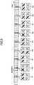
- FIG. 3 illustrates examples of selection of antennas for transmission of reference signals.
- a part of antennas of the 4X4 antenna array is used for transmission of reference signals.
- the antennas #0, #1, #2, and #3 positioned at the center of the antenna array are used.
- a phase difference or an amplitude difference in channels between horizontally adjacent antennas can be estimated between antenna #0 and antenna #1.
- a phase difference or an amplitude difference in channels between vertically adjacent antennas can be estimated between antenna #0 and antenna #2.
- a phase difference or an amplitude difference in channels between the reference antenna #0 and other antennas positioned outside the antennas #0 through #3 can be estimated by extrapolation.
- antennas #0, #1, #2 and #3 positioned at the corners of the antenna array are used for transmission of reference signals.
- a phase difference or an amplitude difference in channels exists between horizontally arranged antennas.
- a phase difference or an amplitude difference of channels exists between vertically arranged antennas.
- a phase difference or an amplitude difference in channels between the reference antenna #0 and other antennas positioned inside the antennas #0 through #3 can be estimated by interpolation.
- a row (or a horizontal line) and a column (or a vertical line) of the antenna array are selected.
- the antenna #0 positioned at the intersection between the selected row and column is the reference antenna.
- a phase difference or an amplitude difference in channels between horizontally arranged antennas can be estimated from the mutual relationship between the antennas #1, #0, #2 and #3 of the selected row.
- a phase difference or an amplitude difference in channels between vertically arranged antennas can be estimated from the mutual relationship between the antennas #4, #0, #5 and #6 of the selected column.
- antennas are arranged, which antennas form 4 polarization antenna elements.
- antenna #0 as the reference antenna
- a phase difference (or an amplitude difference) in channels between horizontally arranged antennas can be estimated between the reference antenna #0 and antenna #1.
- a phase difference or an amplitude difference between polarizations can be estimated between the reference antenna #0 and antenna #2.
- a phase difference (or an amplitude difference) in channels between vertically arranged antennas can be estimated between the reference antenna #0 and antenna #3.
- the radio base station 10 transmits a reference signal using only a part of the antennas, thereby reducing downlink resource consumption.
- the user equipment 20-1 and 20-2 report channel information relative to the reference antenna #0 to the radio base station 10, thereby reducing the feedback overhead.
- the reference antenna #0 may be determined in advance by selecting a suitable antenna. As an alternative, the reference antenna #0 may be configured semi-statically with a higher layer.
- CSI-RS channel status information reference signal
- CRS cell-specific reference signal
- DRS demodulation reference signal
- a newly provided reference signal may be transmitted as the reference signal.
- FIG. 4 through FIG. 7 illustrate examples of transmission of reference signals.
- horizontal channel estimation, vertical channel estimation, and inter-polarization channel estimation are performed using two or more RS sequences.
- CSI-RS configuration information supplied from an higher layer may be used to perform horizontal, vertical, and inter-polarization channel estimations.
- a reference signal is transmitted in horizontal configuration C1.
- a reference signal is transmitted in polarization configuration C2.
- a reference signal is transmitted in vertical configuration C3.
- the resource allocation rate for RS transmission with the horizontal configuration C1 is set the greatest.
- the resource allocation rate for RS transmission with the polarization configuration C2 is set the second greatest.
- the resource allocation rate for RS transmission with the vertical configuration C3 is set smaller than other configurations (C1 and C2 in this example).
- the configuration group ⁇ C1, C2, C3 ⁇ used for the RS transmission may be instructed to be used by the higher layer.
- three configurations are used in FIG. 4 , the invention is not limited to these examples and only two configurations may be used.
- a combination of antennas #0, #1, and #2 of pattern (D) of FIG. 3 may be used as the first configuration C1, which configuration may be named "horizontal-and-polarization configuration".
- the vertical configuration C3 of FIG. 4 may be used as the second configuration.
- the user equipment 20-1 and 20-2 that received the referenced signal in two or more configurations may employ different feedback schemes corresponding to different configurations. For example, a horizontal channel estimate value and an inter-polarization channel estimate value (or precoding vectors selected based upon these channel estimate values) may be reported as feedback information to the radio base station 10 by means of LTE 4 Tx codebooks. A vertical channel estimate value or the precoding vector selected based upon the channel estimate value may be fed back to the radio base station 10 by another codebook or a precoded reference signal index (such as precoded CSI-RS index). The radio base station 10 may designate and report the feedback scheme to be used to the user equipment 20-1 and 20-2.
- the radio base station 10 may dynamically change over antenna groups used for multiplexing the reference signal.
- FIG. 5 and FIG. 6 illustrate examples of changing over antennas to which CSI-RS is mapped along the time axis.
- RS transmission overhead is reduced by transmitting reference signals in two or more RS configurations using a part of antenna elements.
- the overhead may also be reduced by dynamically changing over antenna elements to which the reference signal is multiplexed.
- a CIS-RS is transmitted every 10 milliseconds in horizontal configuration C1, and transmitted every 20 milliseconds in polarization configuration C2 and in vertical configuration C3.
- the configuration to be used and the transmission period may be reported from the radio base station 10 to the user equipment 20-1 and 20-2.
- the user equipment 20-1 and 20-2 may carry out independent feedback operations for the respective configurations.
- FIG. 6 illustrates another example of changeover of RS configurations.
- a reference signal is transmitted every 5 milliseconds in horizontal-and-polarization configuration C5, and this configuration C5 is overridden by another configuration C6 every 20 milliseconds.
- the reference signal transmitted in configuration C6 is used vertical channel estimation and inter-polarization channel estimation.
- the overriding period (20 milliseconds in this example) may be reported from the radio base station 10 to the user equipment 20-1 and 20-2.
- the reference signal is transmitted every 20 milliseconds in configuration C6 for vertical and inter-polarization channel estimations
- the invention is not limited to this example.
- Another configuration for horizontal, vertical, and inter-polarization channel estimations may be used in place of C6.
- the horizontal channel estimate value and the inter-polarization channel estimate value may be fed back by an LTE 4 Tx codebook, and the horizontal, vertical, and inter-polarization channel estimate values may be fed back by an LTE 8 Tx codebook.
- Reference signals may be multiplexed in different configurations along the frequency axis. Multiplexing granularity may be selected arbitrarily, for example, on the sub-band basis, sub-carrier basis, or other frequency basis.
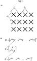
- FIG. 7 is a diagram explaining the feedback method according to the embodiment.
- 24 antenna ports, each antenna port corresponding to one antenna are arranged two-dimensionally.
- the phase rotation of channels between horizontally adjacent antenna #0 and antenna #1 is ⁇ 1.
- the phase rotation of channels between antenna #3 and antenna #4 serving as polarization elements is ⁇ 2.
- the phase rotation of channels between vertically adjacent antenna #0 and antenna #2 is 63.
- channel information in the vertical direction is incorporated in the precoding vector W which is to be fed back to the radio base station 10.
- matrix X including phase rotation (or a phase difference) ⁇ 1 between horizontally adjacent antennas is created by formula (1).
- X e j 0 ⁇ 1 e j 1 ⁇ 1 ... e jm ⁇ 1 T
- m denotes the number of antennas in the horizontal direction
- T denote transposed matrix.
- matrix Y including phase rotation (or a phase difference) ⁇ 2 between polarizations is created by formula (2).
- Y X e j ⁇ 2 X
- the previously created matrix X representing the channel information in the horizontal direction is incorporated in this matrix Y.
- matrix W containing a phase rotation (or a phase difference) ⁇ 3 between vertically adjacent antennas is created by formula (3).
- X e j 0 ⁇ 3 Y e j 1 ⁇ 3 Y ... e jn ⁇ 3 Y T
- n denotes the number of antennas in the vertical direction
- T denotes transposed matrix.
- This matrix W incorporates the matrix Y in which matrix X has been incorporated.
- channel information between horizontally adjacent antennas, channel information between polarization, and channel information between vertically adjacent antennas can be fed back to the radio base station 10. Consequently, overhead of feedback information can be efficiently reduced.
- the creation of the feedback information exemplified in FIG. 7 is for rank-1 transmission.
- the feedback information creation scheme can be extended to rank-2 or higher-rank transmission.
- other values may be used as the channel information.
- an absolute value of phase rotation, a relative or absolute value of amplitude fluctuation, or a long-period or short-period fluctuation characteristic may be used as the channel information.
- the existing 2D-MIMO codebooks may be extended to 3D-MIMO.
- the extended vector W is expressed by formula (4).
- W e j 0 ⁇ 3 X e j 1 ⁇ 3 X ... e jn ⁇ 3 X T
- n denotes the number of antennas in the vertical direction
- ⁇ 3 denotes a phase rotation (or phase difference) between vertically adjacent antennas
- X denotes a codebook achieving 2D-MIMO.
- As the codebook for achieving 2D-MIMO existing 2 Tx codebooks, 4 Tx codebooks, 8 Tx codebooks, codebooks discussed in LTE Release 12 DL-MIMO, or codebooks used in uplink transmission may be used.
- Formula (4) is for rank-1 transmission, it can be extended to rank-2 or higher-rank transmission by using a matrix orthogonal to the matrix W.
- 2D-MIMO codebooks may be used as they are. Since 2D-MIMO codebooks are not designed for including three factors, namely, horizontal channel information, vertical channel information, and inter-polarization channel information, the accuracy may be slightly degraded. However, using 2D-MIMO codebooks is still an effective method because the channel fluctuation in the vertical direction is gentle and because there is little impact on the exiting specification.
- time selectivity and frequency selectivity vary among the horizontal direction, the vertical direction, and inter-polarization. Accordingly, temporal feedback frequency and/or transmission bandwidth of feedback information may be appropriately selected.
- feedback may be carried out less frequently and at a broadband to reduce overhead.
- Feedback may be carried out dynamically at a lower layer or semi-statically at a higher layer, or alternatively, dynamic feedback at a lower layer and semi-static feedback at a higher layer may be combined.
- the number of bits for feedback information in the horizontal direction, the vertical direction, and inter-polarization may be the same or different from one another.
- phase rotation in the horizontal direction, the vertical direction, and inter-polarization may not be always acceptable.
- the phase rotation ⁇ 3 in the vertical direction physically corresponds to a tilt angle, as illustrated in the bottom part (B) of FIG. 1 . It may be effective to limit the selectable range of the ⁇ 3 value.
- Several candidates for ⁇ 3 may be set at each radio base station 10. The candidate values may be reported by a higher layer, and an appropriate value may be selected dynamically at a lower layer for changing over the value.
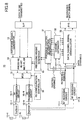
- FIG. 8 is a schematic diagram of the radio base station 10 used in the radio communication system 1 of FIG. 1 .
- the radio base station 10 has multiple antennas 11-1 to 11-N.
- Radio frequency (RF) transmission circuits 16-1 to 16-N and RF receiving circuits 17-1 to 17-N are provided according to the number of antennas 21-1 to 21-N.
- a reference signal generator 13 generates a reference signal used for channel estimation.
- a precoding weight generator 19 generates a precoding weight vector based upon received feedback information supplied via the RF receiving circuits 17-1 through 17-N.
- a precoding weight multiplier 14 performs precoding on the reference signal and data signal using the generated precoding weight vector.
- the data signal input to the precoding weight multiplier 14 has been subjected to serial-to-parallel conversion, channel coding, and modulation. Since these operations are not directly related to the invention, processing blocks are omitted in the figure.
- a multiplexer (MUX) 15 multiplexes the precoded reference signal and data signal.
- An RS configuration controller 18 controls selection and changeover of configurations of reference signal (RS) transmission.
- the RS configuration controller 18 controls allocation of resources to different RS configurations, as illustrated in FIG. 4 .
- the RS configuration controller 18 controls transmission timings or overriding timings of RF configurations, as illustrated in FIG. 5 or FIG. 6 .
- the reference signal is multiplexed to a sequence corresponding the RS configuration to be used.
- the multiplexed signal is transmitted via the RF transmission circuits 16-1 through 16-N and duplexers 12-1 through 12-N.
- a feedback signal from user equipment 20 is received at antennas 11-1 through 11-n, and supplied via the duplexers 12-1 through 12-N and the RF receiving circuits 17-1 through 17-N to a feedback control information demodulator 31.
- Demodulation results are supplied from the feedback control information demodulator 31 to the precoding weight generator 19, and a precoding weight vector is generated according to the feedback information.
- Channel estimation performed by a channel estimator 32
- demodulation of data signal performed by a data channel signal demodulator 33
- decoding operations are not directly related to the invention, and explanation is omitted.
- FIG. 9 is a schematic block diagram of user equipment 20.
- the user equipment 20 receives the reference signal transmitted from the radio base station 10 at RF receiving circuits 24-1 to 24-M through antennas 21-1 to 21-M and duplexers 22-1 to 22-M.
- a channel estimator 25 estimates a channel based upon the received reference signal.
- a precoding weight selector 27 selects a precoding weight vector according to the channel estimation value.
- a channel quality (CQI) measurement unit 26 measures a channel quality based upon the received reference signal.
- CQI channel quality
- the channel quality measurement result and the selection result of the precoding weight vector are supplied to a feedback control signal generator 28.
- the feedback control signal generator 28 generates a feedback signal to be reported to the radio base station 10.
- the feedback signal may include a precoding matrix W expressed by formula (3), containing channel information of the horizontal direction, the vertical direction, and inter-polarization.
- the feedback signal may also include a precoding matrix W expressed by formula (4), extending an existing 2D-MIMO codebook in the vertical direction.
- the feedback signal may include an existing 2D-MIMO codebook.
- a user reference signal and a user data signal are precoded at a precoding weight multiplier 31, and supplied to a multiplexer (MUX) 32.
- the multiplexer 32 multiplexes the precoded user reference signal and user data signal to form the generated feedback signal.
- the multiplexed signal is transmitted from antennas 21-1 to 21-M, via the RF transmission circuits 23-1 to 23-M and duplexers 22-1 to 22-M.
- transmission overhead of channel-estimation reference signals can be reduced in a 3D-MIMO radio communication system employing elevation beamforming. Transmission overhead is also reduced in feedback of channel characteristics.
- the invention is also applicable to uplink transmission.
- a mobile terminal user equipment
- the above-described reference signal configurations or the feedback schemes can be applied.
- three-dimensional channel estimation can be performed based upon the receiving results of the downlink reference signal, and uplink beamforming making use of uplink-downlink duality.
- DFT discrete Fourier transform
Landscapes
- Engineering & Computer Science (AREA)
- Signal Processing (AREA)
- Computer Networks & Wireless Communication (AREA)
- Physics & Mathematics (AREA)
- Mathematical Physics (AREA)
- Electromagnetism (AREA)
- Power Engineering (AREA)
- Radio Transmission System (AREA)
- Monitoring And Testing Of Transmission In General (AREA)
Applications Claiming Priority (2)
| Application Number | Priority Date | Filing Date | Title |
|---|---|---|---|
| JP2013079277A JP2014204305A (ja) | 2013-04-05 | 2013-04-05 | 無線通信システム、無線基地局装置、およびユーザ装置 |
| EP14778403.7A EP2983319A4 (fr) | 2013-04-05 | 2014-03-03 | Système de radiocommunication, dispositif station de base radio et dispositif utilisateur |
Related Parent Applications (1)
| Application Number | Title | Priority Date | Filing Date |
|---|---|---|---|
| EP14778403.7A Division EP2983319A4 (fr) | 2013-04-05 | 2014-03-03 | Système de radiocommunication, dispositif station de base radio et dispositif utilisateur |
Publications (1)
| Publication Number | Publication Date |
|---|---|
| EP3203650A1 true EP3203650A1 (fr) | 2017-08-09 |
Family
ID=51658109
Family Applications (2)
| Application Number | Title | Priority Date | Filing Date |
|---|---|---|---|
| EP17162534.6A Ceased EP3203650A1 (fr) | 2013-04-05 | 2014-03-03 | Système de radiocommunication, appareil de station de base radio et équipement utilisateur |
| EP14778403.7A Withdrawn EP2983319A4 (fr) | 2013-04-05 | 2014-03-03 | Système de radiocommunication, dispositif station de base radio et dispositif utilisateur |
Family Applications After (1)
| Application Number | Title | Priority Date | Filing Date |
|---|---|---|---|
| EP14778403.7A Withdrawn EP2983319A4 (fr) | 2013-04-05 | 2014-03-03 | Système de radiocommunication, dispositif station de base radio et dispositif utilisateur |
Country Status (4)
| Country | Link |
|---|---|
| US (2) | US20160065388A1 (fr) |
| EP (2) | EP3203650A1 (fr) |
| JP (1) | JP2014204305A (fr) |
| WO (1) | WO2014162805A1 (fr) |
Families Citing this family (30)
| Publication number | Priority date | Publication date | Assignee | Title |
|---|---|---|---|---|
| CN106471751A (zh) * | 2014-08-15 | 2017-03-01 | 富士通株式会社 | 资源配置方法、装置以及通信系统 |
| CN112448747A (zh) * | 2014-09-12 | 2021-03-05 | 索尼公司 | 无线通信设备和无线通信方法 |
| US9425875B2 (en) | 2014-09-25 | 2016-08-23 | Intel IP Corporation | Codebook for full-dimension multiple input multiple output communications |
| EP3203649A4 (fr) * | 2014-10-01 | 2018-06-06 | LG Electronics Inc. | Procédé de configuration de signal de référence pour mimo tridimensionnel dans un système de communication sans fil et appareil pour cela |
| CN111884957B (zh) * | 2015-01-28 | 2023-05-16 | 索尼公司 | 无线通信设备和无线通信方法 |
| WO2016121251A1 (fr) | 2015-01-29 | 2016-08-04 | ソニー株式会社 | Dispositif et procédé |
| US11153767B2 (en) | 2015-01-29 | 2021-10-19 | Sony Corporation | Apparatus and method for transmitting measurement restriction and configuration information |
| JP2016143916A (ja) | 2015-01-29 | 2016-08-08 | ソニー株式会社 | 装置 |
| CN104836604B (zh) * | 2015-03-09 | 2018-02-27 | 复旦大学 | 一种基于3d‑mimo系统带噪信道系数的角度域稀疏波束成形算法 |
| US10312975B2 (en) | 2015-03-24 | 2019-06-04 | Sony Corporation | Apparatus |
| EP4246866A3 (fr) | 2015-03-24 | 2023-12-20 | Sony Group Corporation | Dispositif |
| JP7002185B2 (ja) * | 2015-07-30 | 2022-01-20 | パナソニック インテレクチュアル プロパティ コーポレーション オブ アメリカ | 送信方法、送信装置、受信方法、受信装置 |
| JP6510358B2 (ja) * | 2015-08-07 | 2019-05-08 | 日本電信電話株式会社 | 無線通信システム及び無線通信方法 |
| JP6725650B2 (ja) * | 2015-09-24 | 2020-07-22 | 株式会社Nttドコモ | 無線基地局及びユーザ装置 |
| JP2017069688A (ja) * | 2015-09-29 | 2017-04-06 | パナソニックIpマネジメント株式会社 | 送信装置及び受信装置およびこれらを用いた通信方法 |
| CN108141257B (zh) * | 2015-10-05 | 2021-06-29 | 瑞典爱立信有限公司 | 考虑从上行链路参考信号波束成形产生的有效下行链路信道的方法和装置 |
| WO2017077753A1 (fr) | 2015-11-05 | 2017-05-11 | ソニー株式会社 | Dispositif et procédé |
| CN106941681B (zh) * | 2016-01-04 | 2020-03-31 | 中兴通讯股份有限公司 | 一种确定天线极化类型的方法、装置及基站 |
| WO2017188173A1 (fr) * | 2016-04-26 | 2017-11-02 | 京セラ株式会社 | Station de base et équipement terminal radioélectrique |
| WO2018025908A1 (fr) * | 2016-08-03 | 2018-02-08 | 株式会社Nttドコモ | Terminal d'utilisateur et procédé de communication sans fil |
| CN107733493B (zh) | 2016-08-10 | 2021-02-12 | 华为技术有限公司 | 用于确定预编码矩阵的方法和装置 |
| WO2018044693A1 (fr) * | 2016-08-31 | 2018-03-08 | Intel Corporation | Maintien d'une connexion de enb source pendant un transfert |
| US20190199379A1 (en) | 2016-09-06 | 2019-06-27 | Telefonaktiebolaget Lm Ericsson (Publ) | Methods and Devices for Determination of Beamforming Information |
| US10630360B2 (en) * | 2016-09-29 | 2020-04-21 | Ntt Docomo, Inc. | Communication device and communication method |
| CN110121854B (zh) | 2016-11-16 | 2022-03-04 | 瑞典爱立信有限公司 | 用于适配前传网络上的负载的方法和设备 |
| US10432273B1 (en) * | 2018-04-12 | 2019-10-01 | Telefonaktiebolaget Lm Ericsson (Publ) | Antenna arrangement for transmitting reference signals |
| US11171682B2 (en) * | 2019-01-30 | 2021-11-09 | Swiftlink Technologies Inc. | Dual polarization millimeter-wave frontend integrated circuit |
| EP3997801A1 (fr) * | 2019-07-12 | 2022-05-18 | Telefonaktiebolaget LM Ericsson (publ) | Extension de ports de signaux de référence pour réseaux d'antennes larges |
| US10659113B1 (en) * | 2019-08-06 | 2020-05-19 | Sprint Communications Company L.P. | Multiple input multiple output (MIMO) control in a wireless access node |
| US11646506B2 (en) * | 2020-12-30 | 2023-05-09 | Qualcomm Incorporated | Techniques for beam-specific phase adjustment in non-co-located dual-polarized antenna arrays |
Citations (2)
| Publication number | Priority date | Publication date | Assignee | Title |
|---|---|---|---|---|
| WO2013024350A2 (fr) * | 2011-08-15 | 2013-02-21 | Alcatel Lucent | Procédés et appareils pour mesure de canal et retour d'informations d'un réseau d'antennes multidimensionnel |
| EP2950458A1 (fr) * | 2013-01-28 | 2015-12-02 | Fujitsu Limited | Procédé de renvoi d'informations d'état de canal, procédé d'émission d'un signal de référence d'informations d'état de canal, équipement d'utilisateur et station de base |
Family Cites Families (33)
| Publication number | Priority date | Publication date | Assignee | Title |
|---|---|---|---|---|
| JP3732364B2 (ja) * | 1999-08-27 | 2006-01-05 | 松下電器産業株式会社 | 通信端末装置及びチャネル推定方法 |
| GB2386476B (en) * | 2002-03-14 | 2004-05-12 | Toshiba Res Europ Ltd | Antenna signal processing systems |
| US7492841B2 (en) * | 2003-01-30 | 2009-02-17 | Andrew Corporation | Relative phase/amplitude detection system |
| US20040221025A1 (en) * | 2003-04-29 | 2004-11-04 | Johnson Ted C. | Apparatus and method for monitoring computer networks |
| CN1567869B (zh) * | 2003-06-30 | 2010-05-05 | 叶启祥 | 可避免干扰损坏并增加空间再用率的干扰控制方法 |
| JP4183592B2 (ja) * | 2003-09-26 | 2008-11-19 | 三洋電機株式会社 | 受信方法および装置 |
| JP4108029B2 (ja) * | 2003-09-29 | 2008-06-25 | 三洋電機株式会社 | キャリブレーション方法およびそれを利用した無線装置 |
| US7391713B2 (en) * | 2003-12-30 | 2008-06-24 | Kiomars Anvari | Phase rotation technique to reduce Crest Factor of multi-carrier signals |
| WO2006013677A1 (fr) * | 2004-08-06 | 2006-02-09 | Brother Kogyo Kabushiki Kaisha | Appareil de réception radio |
| JP4689435B2 (ja) * | 2004-12-16 | 2011-05-25 | アルプス電気株式会社 | 角度検出センサ |
| US20070110092A1 (en) * | 2005-05-13 | 2007-05-17 | Texas Instruments Incorporated | System and method to support priority in wireless LAN mesh networks |
| US7558330B2 (en) * | 2005-12-07 | 2009-07-07 | Telefonaktiebolaget L M Ericsson (Publ) | Multiple stream co-phasing for multiple-input-multiple-output (MIMO) systems |
| US20070206700A1 (en) | 2006-03-06 | 2007-09-06 | Mediatek Inc. | Quadrature Amplitude Modulation receiver and diagnostic method thereof |
| US8331946B2 (en) * | 2008-03-06 | 2012-12-11 | Qualcomm Incorporated | Methods and apparatus for supporting multiple users in a system with multiple polarized antennas |
| JP2010016572A (ja) | 2008-07-02 | 2010-01-21 | Fujitsu Ltd | 無線通信装置及びシステム |
| US8199708B2 (en) * | 2008-12-30 | 2012-06-12 | Telefonaktiebolaget L M Ericsson (Publ) | Allocation of uplink reference signals in a mobile communication system |
| JP5418598B2 (ja) * | 2009-09-15 | 2014-02-19 | 富士通株式会社 | 無線通信システム、無線通信装置および無線通信方法 |
| US9667378B2 (en) * | 2009-10-01 | 2017-05-30 | Telefonaktiebolaget Lm Ericsson (Publ) | Multi-granular feedback reporting and feedback processing for precoding in telecommunications |
| US8891647B2 (en) * | 2009-10-30 | 2014-11-18 | Futurewei Technologies, Inc. | System and method for user specific antenna down tilt in wireless cellular networks |
| US20110117926A1 (en) * | 2009-11-17 | 2011-05-19 | Mediatek Inc. | Network-based positioning mechanism and reference signal design in OFDMA systems |
| US8787343B2 (en) * | 2009-11-17 | 2014-07-22 | Qualcomm Incorporated | Efficient method for determining a preferred antenna pattern |
| JP5637486B2 (ja) * | 2009-12-17 | 2014-12-10 | マーベル ワールド トレード リミテッド | 交差偏波アンテナ用のmimoフィードバックスキーム |
| JP5152207B2 (ja) * | 2010-01-11 | 2013-02-27 | 株式会社デンソー | 多相回転機の制御装置 |
| KR20110094857A (ko) * | 2010-02-18 | 2011-08-24 | 삼성전자주식회사 | 도달각을 추정하는 방법 및 그 장치 |
| US8488497B2 (en) | 2010-06-10 | 2013-07-16 | Panasonic Corporation | Transmission circuit and transmission method |
| US8787248B2 (en) * | 2010-07-14 | 2014-07-22 | Qualcomm Incorporated | Method in a wireless repeater employing an antenna array including vertical and horizontal feeds for interference reduction |
| EP3761534B1 (fr) | 2010-10-28 | 2023-05-03 | Vivo Mobile Communication Co., Ltd. | Procédé et appareil d'ajustement de puissance d'émission de signal de référence de sondage |
| WO2013006194A1 (fr) * | 2011-07-01 | 2013-01-10 | Intel Corporation | Livre de codes structuré pour réseau circulaire uniforme (uca) |
| CN102938662B (zh) * | 2011-08-15 | 2015-09-16 | 上海贝尔股份有限公司 | 用于3d天线配置的码本设计方法 |
| KR101828836B1 (ko) * | 2011-08-23 | 2018-02-13 | 삼성전자주식회사 | 빔 포밍 기반의 무선통신시스템에서 빔 스캐닝을 통한 스케줄링 장치 및 방법 |
| CN104335505A (zh) * | 2012-03-30 | 2015-02-04 | 诺基亚通信公司 | 用于每用户高程mimo的反馈方法 |
| US9119209B2 (en) * | 2012-03-30 | 2015-08-25 | Samsung Electronics Co., Ltd. | Apparatus and method for channel-state-information pilot design for an advanced wireless network |
| US9306646B2 (en) * | 2013-01-02 | 2016-04-05 | Lg Electronics Inc. | Method and apparatus for receiving downlink radio signal |
-
2013
- 2013-04-05 JP JP2013079277A patent/JP2014204305A/ja active Pending
-
2014
- 2014-03-03 US US14/781,763 patent/US20160065388A1/en not_active Abandoned
- 2014-03-03 EP EP17162534.6A patent/EP3203650A1/fr not_active Ceased
- 2014-03-03 EP EP14778403.7A patent/EP2983319A4/fr not_active Withdrawn
- 2014-03-03 WO PCT/JP2014/055294 patent/WO2014162805A1/fr active Application Filing
-
2018
- 2018-11-14 US US16/190,881 patent/US10652048B2/en active Active
Patent Citations (2)
| Publication number | Priority date | Publication date | Assignee | Title |
|---|---|---|---|---|
| WO2013024350A2 (fr) * | 2011-08-15 | 2013-02-21 | Alcatel Lucent | Procédés et appareils pour mesure de canal et retour d'informations d'un réseau d'antennes multidimensionnel |
| EP2950458A1 (fr) * | 2013-01-28 | 2015-12-02 | Fujitsu Limited | Procédé de renvoi d'informations d'état de canal, procédé d'émission d'un signal de référence d'informations d'état de canal, équipement d'utilisateur et station de base |
Non-Patent Citations (4)
| Title |
|---|
| ALCATEL-LUCENT ET AL: "Way Forward on 8 Tx Codebook for Rel. 10 DL MIMO", 3GPP TSG RAN WG1 MEETING #62, R1-105011, August 2010 (2010-08-01) |
| ALCATEL-LUCENT SHANGHAI BELL ET AL: "Considerations on CSI feedback enhancements for high-priority antenna configurations", 3GPP DRAFT; R1-112420 CONSIDERATIONS ON CSI FEEDBACK ENHANCEMENTS FOR HIGH-PRIORITY ANTENNA CONFIGURATIONS_CLEAN, 3RD GENERATION PARTNERSHIP PROJECT (3GPP), MOBILE COMPETENCE CENTRE ; 650, ROUTE DES LUCIOLES ; F-06921 SOPHIA-ANTIPOLIS CEDEX ; FRANCE, vol. RAN WG1, no. Athens, Greece; 20110822, 18 August 2011 (2011-08-18), XP050537814 * |
| NOKIA SIEMENS NETWORKS: "Study on Downlink Enhancement for Elevation Beamforming for LTE", 3GPP TSG RAN#58, RP-121994 |
| SAMSUNG: "New SID proposal: Study on Full Dimension for LTE", 3GPP TSG RAN#58, RP-122015, December 2012 (2012-12-01) |
Also Published As
| Publication number | Publication date |
|---|---|
| US20190103994A1 (en) | 2019-04-04 |
| JP2014204305A (ja) | 2014-10-27 |
| EP2983319A1 (fr) | 2016-02-10 |
| US10652048B2 (en) | 2020-05-12 |
| WO2014162805A1 (fr) | 2014-10-09 |
| EP2983319A4 (fr) | 2016-03-02 |
| US20160065388A1 (en) | 2016-03-03 |
Similar Documents
| Publication | Publication Date | Title |
|---|---|---|
| US10652048B2 (en) | 3-D MIMO communication system, radio base station, and user equipment | |
| US10530449B2 (en) | Reporting of channel state information | |
| CN110168947B (zh) | 在无线通信系统中的上行链路发送/接收方法及其装置 | |
| US9537552B2 (en) | Method and apparatus for channel state information based on antenna mapping and subsampling | |
| US9401750B2 (en) | Method and precoder information feedback in multi-antenna wireless communication systems | |
| KR102258289B1 (ko) | 이차원 배열 안테나를 사용하는 이동통신 시스템에서의 채널 피드백의 생성 및 전송 방법 및 장치 | |
| US8509338B2 (en) | Method and precoder information feedback in multi-antenna wireless communication systems | |
| KR102059125B1 (ko) | 셀룰러 무선 통신 시스템을 위한 채널 상태 정보 코드워드 구성 장치 및 방법 | |
| KR102064939B1 (ko) | 다수의 이차원 배열 안테나를 사용하는 이동통신 시스템에서의 피드백 송수신 방법 및 장치 | |
| KR101893161B1 (ko) | 무선 통신 시스템에서 3 차원 mimo를 위한 피드백 정보 산출 방법 및 이를 위한 장치 | |
| WO2016051792A1 (fr) | Procédé et système de communication mimo | |
| CN106465170B (zh) | 信息处理方法、基站和用户设备 | |
| KR20160010443A (ko) | 무선 통신 시스템에서 분할 빔포밍을 위하여 단말이 피드백 정보를 전송하는 방법 및 이를 위한 장치 | |
| KR20150143422A (ko) | 무선 통신 시스템에서 분할 빔포밍을 위한 채널 상태 정보 보고 방법 및 이를 위한 장치 | |
| KR20160012129A (ko) | 무선 통신 시스템에서 3 차원 빔포밍을 위한 채널 상태 정보 보고 방법 및 이를 위한 장치 | |
| KR20150140276A (ko) | 무선 통신 시스템에서 분할 빔포밍을 위한 제어 정보 제공 방법 및 이를 위한 장치 | |
| CN108886426B (zh) | 用于无线通信的用户设备和方法 | |
| CN110233648B (zh) | 确定预编码矩阵指示的方法、装置,以及用户设备和基站 | |
| KR102381159B1 (ko) | 다중 안테나 무선 통신 시스템에서 채널 측정을 위한 참조 신호 전송 방법 및 이를 위한 장치 | |
| WO2018026073A1 (fr) | Procédé de transmission d'informations de rétroaction d'entrées multiples sorties multiples (mimo) tridimensionnelles en fonction d'un signal de référence en forme de faisceau dans un système de communication sans fil et appareil s'y rapportant | |
| KR20210076905A (ko) | 무선 통신 시스템을 위한 도플러 코드북-기반 프리코딩 및 csi 보고 | |
| JP6085697B2 (ja) | ユーザ装置および無線基地局 | |
| WO2022106730A1 (fr) | Rapport de csi basé sur un livre de codes à combinaison linéaire | |
| CN117957789A (zh) | 用于在无线通信网络中联合传输的csi报告的方法和装置 |
Legal Events
| Date | Code | Title | Description |
|---|---|---|---|
| PUAI | Public reference made under article 153(3) epc to a published international application that has entered the european phase |
Free format text: ORIGINAL CODE: 0009012 |
|
| 17P | Request for examination filed |
Effective date: 20170323 |
|
| AC | Divisional application: reference to earlier application |
Ref document number: 2983319 Country of ref document: EP Kind code of ref document: P |
|
| AK | Designated contracting states |
Kind code of ref document: A1 Designated state(s): AL AT BE BG CH CY CZ DE DK EE ES FI FR GB GR HR HU IE IS IT LI LT LU LV MC MK MT NL NO PL PT RO RS SE SI SK SM TR |
|
| 17Q | First examination report despatched |
Effective date: 20180720 |
|
| STAA | Information on the status of an ep patent application or granted ep patent |
Free format text: STATUS: THE APPLICATION HAS BEEN REFUSED |
|
| 18R | Application refused |
Effective date: 20191112 |