EP3203140B1 - Lighting device for a vehicle and associated operating method - Google Patents
Lighting device for a vehicle and associated operating method Download PDFInfo
- Publication number
- EP3203140B1 EP3203140B1 EP17154052.9A EP17154052A EP3203140B1 EP 3203140 B1 EP3203140 B1 EP 3203140B1 EP 17154052 A EP17154052 A EP 17154052A EP 3203140 B1 EP3203140 B1 EP 3203140B1
- Authority
- EP
- European Patent Office
- Prior art keywords
- light distribution
- lighting device
- distorted
- light
- anamorphic element
- Prior art date
- Legal status (The legal status is an assumption and is not a legal conclusion. Google has not performed a legal analysis and makes no representation as to the accuracy of the status listed.)
- Active
Links
- 238000011017 operating method Methods 0.000 title 1
- 238000009826 distribution Methods 0.000 claims description 89
- 230000003287 optical effect Effects 0.000 claims description 21
- 230000007423 decrease Effects 0.000 claims description 9
- 238000000034 method Methods 0.000 claims description 9
- OAICVXFJPJFONN-UHFFFAOYSA-N Phosphorus Chemical compound [P] OAICVXFJPJFONN-UHFFFAOYSA-N 0.000 claims description 7
- 230000000694 effects Effects 0.000 description 9
- 238000005286 illumination Methods 0.000 description 9
- 239000000463 material Substances 0.000 description 7
- 230000003993 interaction Effects 0.000 description 4
- 230000008901 benefit Effects 0.000 description 3
- 230000006978 adaptation Effects 0.000 description 2
- 238000004891 communication Methods 0.000 description 2
- 238000013461 design Methods 0.000 description 2
- 238000003384 imaging method Methods 0.000 description 2
- 238000009434 installation Methods 0.000 description 2
- 238000012986 modification Methods 0.000 description 2
- 230000004048 modification Effects 0.000 description 2
- 239000004033 plastic Substances 0.000 description 2
- 229920003023 plastic Polymers 0.000 description 2
- 230000008092 positive effect Effects 0.000 description 2
- 241000283070 Equus zebra Species 0.000 description 1
- 239000006096 absorbing agent Substances 0.000 description 1
- 238000004364 calculation method Methods 0.000 description 1
- 239000011248 coating agent Substances 0.000 description 1
- 238000000576 coating method Methods 0.000 description 1
- 230000006835 compression Effects 0.000 description 1
- 238000007906 compression Methods 0.000 description 1
- 230000003247 decreasing effect Effects 0.000 description 1
- 230000001419 dependent effect Effects 0.000 description 1
- 238000001514 detection method Methods 0.000 description 1
- 238000011161 development Methods 0.000 description 1
- 230000018109 developmental process Effects 0.000 description 1
- 230000005670 electromagnetic radiation Effects 0.000 description 1
- 239000012530 fluid Substances 0.000 description 1
- 230000004313 glare Effects 0.000 description 1
- 239000011521 glass Substances 0.000 description 1
- 230000010354 integration Effects 0.000 description 1
- 230000007794 irritation Effects 0.000 description 1
- 238000004519 manufacturing process Methods 0.000 description 1
- 239000011159 matrix material Substances 0.000 description 1
- 238000009828 non-uniform distribution Methods 0.000 description 1
- 238000012634 optical imaging Methods 0.000 description 1
- 230000002093 peripheral effect Effects 0.000 description 1
- 238000012887 quadratic function Methods 0.000 description 1
- 230000005855 radiation Effects 0.000 description 1
- 230000000630 rising effect Effects 0.000 description 1
- 230000001953 sensory effect Effects 0.000 description 1
- 238000007493 shaping process Methods 0.000 description 1
- 230000003595 spectral effect Effects 0.000 description 1
Images

Classifications
-
- F—MECHANICAL ENGINEERING; LIGHTING; HEATING; WEAPONS; BLASTING
- F21—LIGHTING
- F21S—NON-PORTABLE LIGHTING DEVICES; SYSTEMS THEREOF; VEHICLE LIGHTING DEVICES SPECIALLY ADAPTED FOR VEHICLE EXTERIORS
- F21S41/00—Illuminating devices specially adapted for vehicle exteriors, e.g. headlamps
- F21S41/20—Illuminating devices specially adapted for vehicle exteriors, e.g. headlamps characterised by refractors, transparent cover plates, light guides or filters
- F21S41/25—Projection lenses
- F21S41/265—Composite lenses; Lenses with a patch-like shape
-
- F—MECHANICAL ENGINEERING; LIGHTING; HEATING; WEAPONS; BLASTING
- F21—LIGHTING
- F21S—NON-PORTABLE LIGHTING DEVICES; SYSTEMS THEREOF; VEHICLE LIGHTING DEVICES SPECIALLY ADAPTED FOR VEHICLE EXTERIORS
- F21S41/00—Illuminating devices specially adapted for vehicle exteriors, e.g. headlamps
- F21S41/10—Illuminating devices specially adapted for vehicle exteriors, e.g. headlamps characterised by the light source
- F21S41/14—Illuminating devices specially adapted for vehicle exteriors, e.g. headlamps characterised by the light source characterised by the type of light source
- F21S41/141—Light emitting diodes [LED]
- F21S41/143—Light emitting diodes [LED] the main emission direction of the LED being parallel to the optical axis of the illuminating device
-
- F—MECHANICAL ENGINEERING; LIGHTING; HEATING; WEAPONS; BLASTING
- F21—LIGHTING
- F21S—NON-PORTABLE LIGHTING DEVICES; SYSTEMS THEREOF; VEHICLE LIGHTING DEVICES SPECIALLY ADAPTED FOR VEHICLE EXTERIORS
- F21S41/00—Illuminating devices specially adapted for vehicle exteriors, e.g. headlamps
- F21S41/10—Illuminating devices specially adapted for vehicle exteriors, e.g. headlamps characterised by the light source
- F21S41/14—Illuminating devices specially adapted for vehicle exteriors, e.g. headlamps characterised by the light source characterised by the type of light source
- F21S41/141—Light emitting diodes [LED]
- F21S41/151—Light emitting diodes [LED] arranged in one or more lines
- F21S41/153—Light emitting diodes [LED] arranged in one or more lines arranged in a matrix
-
- F—MECHANICAL ENGINEERING; LIGHTING; HEATING; WEAPONS; BLASTING
- F21—LIGHTING
- F21S—NON-PORTABLE LIGHTING DEVICES; SYSTEMS THEREOF; VEHICLE LIGHTING DEVICES SPECIALLY ADAPTED FOR VEHICLE EXTERIORS
- F21S41/00—Illuminating devices specially adapted for vehicle exteriors, e.g. headlamps
- F21S41/10—Illuminating devices specially adapted for vehicle exteriors, e.g. headlamps characterised by the light source
- F21S41/14—Illuminating devices specially adapted for vehicle exteriors, e.g. headlamps characterised by the light source characterised by the type of light source
- F21S41/176—Light sources where the light is generated by photoluminescent material spaced from a primary light generating element
-
- F—MECHANICAL ENGINEERING; LIGHTING; HEATING; WEAPONS; BLASTING
- F21—LIGHTING
- F21S—NON-PORTABLE LIGHTING DEVICES; SYSTEMS THEREOF; VEHICLE LIGHTING DEVICES SPECIALLY ADAPTED FOR VEHICLE EXTERIORS
- F21S41/00—Illuminating devices specially adapted for vehicle exteriors, e.g. headlamps
- F21S41/20—Illuminating devices specially adapted for vehicle exteriors, e.g. headlamps characterised by refractors, transparent cover plates, light guides or filters
- F21S41/25—Projection lenses
-
- F—MECHANICAL ENGINEERING; LIGHTING; HEATING; WEAPONS; BLASTING
- F21—LIGHTING
- F21S—NON-PORTABLE LIGHTING DEVICES; SYSTEMS THEREOF; VEHICLE LIGHTING DEVICES SPECIALLY ADAPTED FOR VEHICLE EXTERIORS
- F21S41/00—Illuminating devices specially adapted for vehicle exteriors, e.g. headlamps
- F21S41/30—Illuminating devices specially adapted for vehicle exteriors, e.g. headlamps characterised by reflectors
- F21S41/32—Optical layout thereof
-
- F—MECHANICAL ENGINEERING; LIGHTING; HEATING; WEAPONS; BLASTING
- F21—LIGHTING
- F21W—INDEXING SCHEME ASSOCIATED WITH SUBCLASSES F21K, F21L, F21S and F21V, RELATING TO USES OR APPLICATIONS OF LIGHTING DEVICES OR SYSTEMS
- F21W2103/00—Exterior vehicle lighting devices for signalling purposes
- F21W2103/60—Projection of signs from lighting devices, e.g. symbols or information being projected onto the road
Definitions
- the invention relates to a lighting device for a vehicle according to the preamble of patent claims 1 and 2 and a method for operating such a lighting device for a vehicle according to the preamble of patent claims 7 and 8.
- anamorphic element By means of an anamorphic element, a light distribution striking it can generally be distorted, for example stretched or compressed. After interaction with the anamorphic element, a distorted image of the irradiated light distribution results.
- the term “light” is not necessarily limited to the spectral range perceivable by humans, but can also refer to other and/or additional frequencies of electromagnetic radiation.
- the US 2014 / 0 092 619 A1 describes a fog lamp with an LED and a refractive/TIR lens, the central area of which is purely refractive, while total internal reflection (TIR) is provided in a peripheral area.
- Converging light emanating from the lens passes through a light guide plate and then through an anamorphic lens.
- the latter forms an emergent light beam that has a wider divergence in a lateral direction than in a vertical direction.
- the anamorphic lens can have a flat side and a ridged side, whereby the corresponding ridges can have a repeating pattern.
- a lighting arrangement for a headlight with several optical imaging elements in which a number of light-emitting diodes are combined in groups to form light-emitting diode fields.
- the imaging elements Using the imaging elements, a height or Width of a light beam generated by a light-emitting diode field can be stretched or compressed.
- the light-emitting diode fields can be arranged offset from an optical axis of a respective associated imaging element. Due to the arrangement, a boundary of a light beam of a light-emitting diode field lies directly on a boundary of a light beam of a light-emitting diode field arranged immediately adjacent. An undistorted image is made possible in a central region of a light distribution, with an increase in the light distribution resulting from a distortion of the outer light bundles.
- the US 2015 / 0 377 442 A1 discloses a vehicle headlight with a DMD, a light source and each with lighting and projection optics. At least one of these elements shapes a light beam in such a way that pixelated light reflected by the DMD has a non-uniform beam profile, which is suitable for projecting a portion of the headlight's overall light beam.
- the total light beam has a low beam part, a high beam part and a middle part. It is intended that the non-uniform distribution of white light on the DMD has a higher intensity centrally, which decreases starting from the center.
- the projection optics may include an anamorphic lens to stretch the DMD light to a field of view (FOV).
- a headlight for vehicles is known with an optical unit arranged in front of a light source unit to generate a predetermined light distribution.
- the optical unit has, on a side facing away from the light source unit, a bulbous light decoupling surface which, at least in a horizontal central section, has a conical shape with a conical constant in a range between -1 and 0.
- the light decoupling surface can be anamorphic and have several different curvature line areas that merge into one another.
- a motor vehicle headlight device in which a light source composed of a plurality of light-emitting elements and a projection lens are arranged at a distance from each other which is smaller than the focal length of the projection lens. This allows more uniform illumination to be achieved by minimizing the effects of the distances between the individual light-emitting elements on the light image.
- a convex and a concave lens can also be provided, which together can form an anamorphic lens system, so that a corresponding shaping of the light distribution is possible.
- the US 2014/0092619 A1 discloses a fog light for a vehicle in which light emitted by an LED is directed through a special lens, which has usual light-refractive properties in a central section and enables total reflection on internal surfaces in external areas.
- An anamorphic lens is provided in the further beam path, by means of which the angular extent of the light beam is to be reduced in a vertical direction and increased in a horizontal direction.
- a surface of the anamorphic lens can have a uniformly repeating pattern such as a vertical groove structure.
- the US 2008/0285293 A1 describes a vehicle exterior mirror, the housing of which houses a light source and a lens arranged in the beam path of the light source.
- the lens can be a cylindrical lens or an anamorphic lens, by means of which an elongated light distribution is to be generated on a floor surface next to the vehicle, which extends essentially in the longitudinal direction of the vehicle.
- the lens is rotatably coupled to a mechanism for folding the exterior mirror, so that the elongated shape of the illuminated surface can be achieved regardless of the position of the exterior mirror.
- the object of the present invention is to provide a lighting device for a vehicle and a method for operating such a lighting device, by means of which a light distribution can be individually designed with as little effort as possible.
- the light distribution can be distorted non-linearly in at least one direction by the anamorphic element, i.e. is distorted. In other words, not all subregions of the light distribution are distorted uniformly in at least one direction, but subregions of the light distribution arranged successively in this direction are distorted to different degrees.
- the degree or the extent of the distortion therefore increases from a first sub-region of the distorted light distribution to a second second sub-region starting from this first sub-region in the said at least one direction, this increase along a sequence of sub-regions extending in the at least one direction follows a non-linear relationship or progression.
- Such a non-linear distortion of the light distribution irradiated by the pixel light source onto the anamorphic element makes it possible to project the light distribution - in particular in the form of patterns or images - onto a surface in the area surrounding the vehicle in a particularly advantageous manner in such a way that a Particularly good visibility can be achieved, especially for observers in the area surrounding the vehicle, and/or more uniform illumination of the illuminated surface can be achieved.
- such a lighting device is provided in particular as or in conjunction with a headlight of the vehicle, but it is also conceivable to use it in almost any other location on the vehicle, for example as a rear headlight or taillight or on the sides of the vehicle.
- the lighting device mounted on a vehicle will, in normal operation, be located above a surface traveled by the vehicle, which for the sake of simplicity will be referred to below as the roadway, regardless of its specific nature.
- the anamorphic element provided in the beam path of the lighting device, in that the undistorted light distribution emitted by the pixel light source is distorted non-linearly by the anamorphic element.
- the anamorphic element is designed in such a way that those pixels or partial areas of the light distribution that contribute to the illumination of parts of the road that are further away from the vehicle are more strongly distorted, i.e. those pixels or partial areas of the light distribution that contribute to the illumination of parts of the road that are closer to the vehicle Contribute to areas of the roadway lying on the vehicle.
- the pixel density on the illuminated surface can be specifically increased using a single anamorphic element, especially in those areas where the greatest positive effect can be achieved due to the given geometry. This represents a significantly less complex and therefore simpler option compared to, for example, the alternative of increasing the pixel density of the pixel light source.
- the anamorphic element can be implemented in various ways, preferably as a transmissive element - such as a lens - or, for example, as a reflective element - such as a mirror element.
- the anamorphic element is designed as a free-form lens.
- a free-form lens can have a flat side facing the pixel light source and an aspherical side opposite it.
- the latter can also have very complex, non-rotationally symmetrical shapes, which enables particularly precise adaptation to the respective circumstances and requirements, such as the exact installation position or position and the desired size and shape of the area that can be illuminated or illuminated.
- a free-form lens can also have any practical shape on both opposite sides or on all sides.
- the anamorphic element is designed as a gradient lens.
- a gradient lens can be independent of its Shape due to inherent material properties have continuously or regionally varying optical properties, in particular refractive properties, and can be realized, for example, by targeted doping of the lens material.
- a gradient lens can, for example, be designed cylindrical, which may simplify assembly or integration into the lighting device and/or improve the utilization of installation space. In principle, however, almost any other shape for a gradient lens is also conceivable. It is also conceivable to implement a multi-layer structure of the gradient lens, for example made of different plastics.
- the anamorphic element is designed as an arrangement of a plurality of lenses or individual lenses, which differ in at least one optical property, in particular a refractive property.
- Such an arrangement can be referred to as a lens array.
- the individual lenses can each be regularly shaped, for example as a half cylinder, which may make it possible to achieve more cost-effective production.
- the individual lenses can then differ from one another, for example in terms of their size, shape, the material used or other properties, provided that the desired effect is achieved overall.
- the invention it is provided that within a sequence of partial areas of the distorted light distribution extending in one direction, respective extensions of the partial areas extending in this direction are distorted by the anamorphic element in accordance with a monotonous square relationship compared to the corresponding partial areas of the undistorted light distribution, for which a curvature of the anamorphic element decreases asymmetrically in this direction.
- the distorted light distribution is the light distribution that occurs immediately after the interaction with the anamorphic element.
- a partial area of the light distribution is assigned or corresponds to a pixel of the pixel light source, all pixels of the pixel light source have the same size or extent in at least one direction and these emitted by the pixel light source,
- Light distribution composed of pixels of the same size is distorted by the anamorphic element in such a way that the extent of the light illuminated by one pixel at a time is distorted
- Areas of the roadway are just constant regardless of the distance from the lighting device or from the vehicle in the lighting direction - that is, for example, when the lighting device is used as a headlight, i.e. in the longitudinal direction of the vehicle.
- a square course of the distortion is particularly advantageous, since the extent in the illumination direction of the illuminated areas on the road, each assigned to a pixel, increases quadratically as the distance from the vehicle increases.
- An anamorphic element which causes a square distortion, can therefore precisely compensate for the effect of pixel enlargement caused by the angle between the light rays emanating from the lighting device and the road or the illuminated surface - that is, by the projection of the light distribution onto the road by compressing parts of the light distribution hitting the vehicle at a flatter angle and thus at a greater distance from the vehicle to a greater extent in accordance with the square of the distance.
- the size of the partial area of the distorted light distribution corresponding to a pixel immediately after interaction with the anamorphic element or at other points in the beam path is therefore not necessarily uniform and only the partial areas or pixels shown as an image on the road have a uniform size again.
- the pixel light source comprises a surface light modulator, in particular a digital micromirror device (DMD).
- DMD digital micromirror device
- Such a DMD has a large number of micromirrors, which can be tilted between at least two positions, so that any light distributions, patterns or images composed of pixels can be generated by targeted control.
- the micromirrors can be tilted accordingly so that the light hitting them is directed to an absorber and does not reach the surroundings of the lighting device or the vehicle.
- the DMD is illuminated directly or indirectly by an active light source and in turn serves as a passive pixel light source that illuminates the anamorphic element.
- this is DMD is therefore arranged in the beam path emanating from the primary, active light source between this active light source and the anamorphic element.
- any high-resolution light distribution can be generated particularly advantageously, with fluid animations or moving images or patterns being able to be generated or displayed without any problems due to the high switching frequency of the micromirror actuators.
- Any areas can also be specifically hidden or darkened so that, for example, vehicles in front or oncoming vehicles or other road users are not illuminated and therefore not blinded.
- the pixel light source is composed of a plurality of active light sources.
- a matrix of individual lasers or LEDs can be provided which directly or indirectly illuminate the anamorphic element, in which case the desired light distribution can be generated by specifically switching the individual light sources on and off.
- the lighting device comprises at least one laser and an optical converter element, in particular a phosphor element, arranged in a beam path of the laser.
- the laser represents the primary, active light source of the lighting device and in the further course of the beam the optical converter element is illuminated, which converts the incident laser radiation into light, which differs in at least one property from that through the light produced by the laser differs.
- at least approximately monochromatic laser light can typically be converted into white light, which is particularly suitable for ambient lighting purposes in the automotive sector.
- the optical converter element can also have a less pronounced point source characteristic or emit light at a larger angle or with greater divergence than the laser.
- the lighting device comprises a sensor system for detecting a surface that can be illuminated by means of the lighting device, wherein a pattern composed of pixels of at least approximately the same size can be generated on the detected surface by means of the lighting device.
- the light distribution emitted from the pixel light source to the anamorphic element can, depending on the data supplied by the sensor system, possibly already be adjusted in such a way that in interaction with the distortion caused by the anamorphic element and the projection geometry on the detected surface a particularly well-recognizable representation or an image of the light distribution results.
- a corresponding sensor system can include a large number of different sensors. These include, for example, radar, ultrasonic and laser sensors as well as cameras and generally optical sensors, with respective corresponding transmitting devices also being provided if necessary.
- the light distribution can be adjusted by specifically controlling the pixel light source, for which, for example, an electronic control unit (ECU) can be provided. It is therefore conceivable to adapt or control the light distribution using appropriately designed software and/or electronics, so that different light distributions or representations can be realized with a single lighting device.
- ECU electronice control unit
- pixels of the pixel light source can be combined or assigned to a larger pixel or partial area of the light distribution.
- the angle between the light rays emanating from the lighting device and the detected illuminated surface can have a particular influence here.
- typical road bumps and inclines typically have only a negligibly small influence, for example a wall rising in front of the vehicle in the direction of illumination approximately perpendicular to the road traveled by the vehicle, a significant modification of the light distribution emitted by the pixel light source may be required in order to achieve this to obtain a representation on the wall - or generally on an inclined surface - composed of pixels of at least approximately the same size.
- the pixel light source does not necessarily have to emit light distributions, patterns or images that are composed of pixels of the same size.
- the anamorphic element would cause a distortion which follows a quadratic relationship along at least one direction.
- the illuminated surface corresponds to the at least essentially flat roadway traveled by the vehicle, but is formed, for example, by any other surface.
- Such other surfaces can be surfaces of other vehicles or surfaces - for example walls - of buildings.
- the anamorphic element is at least partially illuminated with a light distribution by means of a pixel light source and this light distribution in at least one direction is distorted non-linearly by the anamorphic element, wherein within a sequence of partial areas of the distorted light distribution extending in this direction, respective extensions of the partial areas extending in this direction according to a monotonous square relationship compared to the corresponding partial areas of the undistorted light distribution by the anamorphic element be distorted, for which purpose a curvature of the anamorphic element (10) decreases asymmetrically in this direction.
- the lighting device according to the invention or the method according to the invention can be used particularly advantageously in each embodiment to transmit information to the environment through targeted representations, that is, for example, to other road users, but also to the respective occupants of the vehicle equipped with the lighting device according to the invention, whereby one For communication purposes, a display or projection with a uniform resolution, i.e. with a uniform pixel size, is particularly desirable.
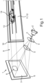
- Fig. 1 shows a schematic and perspective representation of the principle of a lighting device 1 with a laser 2 as the primary active light source, which emits a laser beam 3.
- a laser 2 as the primary active light source
- several optical elements are arranged in a beam path of the laser 2 or the laser beam 3, with the lighting device 1 as a whole being designed as a headlight.
- the Sequence in the beam path starting from the laser 2 describes the optical elements arranged in the beam path.
- the laser beam 3 first hits an optical converter element, which in the present case is designed as a phosphor element 4 and stimulates it to glow or to convert the irradiated, for example blue, laser light into white light.
- an optical converter element which in the present case is designed as a phosphor element 4 and stimulates it to glow or to convert the irradiated, for example blue, laser light into white light.
- the laser 2 represents a very bright point light source that emits an intense light beam with little divergence
- the phosphor element 4 can emit a less strongly directed cone of white light.
- the phosphor element 4 can also be shaped accordingly, in that the desired beam expansion is supported, for example, by convex surfaces or generally a lens shape.
- a refractive element in the form of a lens 5 is provided in the beam path, which is to be understood here as an example and can also be representative of several optical elements.
- the light emitted by the phosphor element 4 is bundled, expanded or generally shaped by the lens or lenses 5, depending on the specific requirements, in order to achieve optimal illumination of subsequent optical elements.
- an optical deflection element in the form of a digital micromirror device (DMD) 6 is arranged in the further path of the beam, which in the present case has an illuminated area or mirror area 7 arranged on a support.
- the individual micromirrors of the DMD 6 can each be viewed as individual pixels, so that a desired light distribution can be generated by specifically adjusting the tilting of the micromirrors.
- several micromirrors can also be combined to form a single pixel of light distribution.
- the DMD 6 illuminated at an angle serves as a passive pixel light source, which emits a predeterminable light distribution 9.
- a hidden area 8 is created by deliberately tilting a subset of micromirrors of the DMD 6, which therefore represents or creates a dark area in the light distribution 9.
- the light distribution 9 emitted by the DMD 6 impinges on an anamorphic element, which in the present case is a single anamorphic lens 10 is realized.
- an anamorphic lens 10 When passing through this anamorphic lens 10, the light distribution 9 is distorted and projected as an image 11 of the light distribution 9 onto a surface in the vicinity of the lighting device 1 - in the present case onto a roadway 12.
- an image 13 of the hidden area 8 can be clearly seen, with a foreign vehicle 14 being shown in this unilluminated area.
- those pixels in the light distribution 9 whose images are displayed at a greater distance from the lighting device 1 in the image 11 of the light distribution 9 on the road 12 are more distorted than those pixels in the light distribution 9 whose images are represented as parts of the Image 11 of the light distribution 9 on the road 12 can be shown closer to the lighting device 1 on the road 12.
- the degree or strength of the distortion increases quadratically from the less distorted to the more strongly distorted pixels of the light distribution 9.
- This quadratic increase in distortion is caused when the thus distorted light distribution is projected onto the roadway 12 by the projection onto the roadway 12, that is to say due to the effect of pixel enlargement that arises due to the angle between the light rays emanating from the lighting device 1 and the roadway 12 increasing distance from the vehicle.
- the light distribution 9 on the road 12 in Figure 11 is independent Depending on the distance from the vehicle or from the lighting device 1, the areas assigned to the individual pixels of the light distribution 9 are of the same size or extend over equally large areas of the road 12.
- a light distribution 9 or an image 11 of a light distribution 9, which is useful for communication and/or information purposes and can be projected onto the roadway 12, can, for example, represent a zebra crossing - possibly also animated or possibly provided with animated arrows - by means of which pedestrians can be signaled that they have been recognized by the vehicle and safe crossing of the road is possible.
- Fig. 2 shows a schematic representation of a distortion pattern 15, which can be understood as a distorted light distribution, which results when a light distribution 9 composed of pixels of the same size passes through the anamorphic lens 10 immediately after it.
- a two-dimensional coordinate system with x and y directions is shown. It can be clearly seen that, for example, pixel 16 is the largest pixel and as the distortion pattern 15 passes through in the y direction, the subsequent pixels become smaller, so that, for example, pixel 17 only has a fraction of the height or extent in the y direction of pixel 16 .
- the x-direction of the distortion pattern 15 describes the extent of the illuminated area on the road 12 in the road and vehicle transverse directions and here the extent of the illuminated area is typically significantly smaller than the extent of the illuminated area on the roadway 12 in the roadway and vehicle longitudinal direction, corresponding to that in the y-direction of the distortion pattern 15.
- This also means the effect of the pixel enlargement caused by the projection in the image 11 of the light distribution 9 on the roadway 12 in the x direction is significantly less pronounced or less noticeable for observers.
- FIG. 3a shows a free-form lens 19, which has a half-lens shape with a flat side 20 and a curved side 21.
- the curvature of the curved side 21 decreases in the negative y-direction, so that a deviation from a spherical shape is present and also clearly recognizable.
- the variant shown shows a lens arrangement 22, which also has a flat side 23.
- the side opposite this flat side 23 is here composed of a plurality of individual lenses 24, 25, 26, 27, each of which has a half-lens or half-cylindrical shape with the same or regular curvature.
- the individual lenses 24 to 27 differ both in their curvature and in their thickness or material thickness, with the corresponding values decreasing in the negative y-direction from one of the individual lenses 24 to 27 to the next. This means that the individual lens 24 has both the greatest thickness or material thickness and the greatest curvature of all individual lenses 24 to 27 and the individual lens 27 correspondingly has the smallest thickness or material thickness and the smallest curvature.
- each of the individual lenses 24 to 27 causes a uniform distortion of the parts of the light distribution 9 passing through them and the described, overall non-linear distortion of the light distribution 9 only arises over the entire area when comparing the respective partial areas.
- an anamorphic lens arrangement 22 composed of individual lenses 24 to 27 in this way, a large number of other variants are conceivable in addition to the one shown schematically here, whereby in principle the individual lenses 24 to 27 do not have to be regularly shaped in themselves, but also as a free-form lens and / or can be designed as a gradient lens.
- the semi-cylindrical shape of the individual lenses 24 to 27 shown here is only to be understood as an example and a hemispherical or other shape would also be conceivable. This means that each individual lens 24 to 27 can be assigned a single or several rows of pixels or a single or several pixels.
- the anamorphic lens 10 can be made of glass or a plastic material, for example.
- a reflection-reducing coating can be provided in order to minimize losses.
- a particularly non-linear distortion of a light distribution 9 can be caused by an anamorphic lens 10 in the beam path of the lighting device 1, whereby a particularly advantageous adjustment of the pixel size or pixel density in the image 11 of the light distribution 9 that is ultimately visible on an illuminated surface can be achieved is.
Landscapes
- Engineering & Computer Science (AREA)
- General Engineering & Computer Science (AREA)
- Physics & Mathematics (AREA)
- Microelectronics & Electronic Packaging (AREA)
- Optics & Photonics (AREA)
- Mathematical Physics (AREA)
- Non-Portable Lighting Devices Or Systems Thereof (AREA)
- Lighting Device Outwards From Vehicle And Optical Signal (AREA)
Description
Die Erfindung betrifft eine Beleuchtungseinrichtung für ein Fahrzeug gemäß dem Oberbegriff des Patentanspruchs 1 und 2 und ein Verfahren zum Betreiben einer solchen Beleuchtungseinrichtung für ein Fahrzeug gemäß dem Oberbegriff des Patentanspruchs 7 und 8.The invention relates to a lighting device for a vehicle according to the preamble of patent claims 1 and 2 and a method for operating such a lighting device for a vehicle according to the preamble of patent claims 7 and 8.
Mittels eines anamorphotischen Elements kann allgemein eine auf dieses auftreffende Lichtverteilung verzerrt, beispielsweise gestreckt oder gestaucht werden. Nach der Interaktion mit dem anamorphotischen Element ergibt sich also ein verzerrtes Abbild der eingestrahlten Lichtverteilung. Im Sinne der vorliegenden Erfindung ist der Begriff "Licht" dabei nicht notwendig auf den vom Menschen wahrnehmbaren Spektralbereich beschränkt, sondern kann sich auch auf andere und/oder zusätzliche Frequenzen elektromagnetischer Strahlung beziehen.By means of an anamorphic element, a light distribution striking it can generally be distorted, for example stretched or compressed. After interaction with the anamorphic element, a distorted image of the irradiated light distribution results. For the purposes of the present invention, the term “light” is not necessarily limited to the spectral range perceivable by humans, but can also refer to other and/or additional frequencies of electromagnetic radiation.
Die
Aus der
Die
Aus der
Aus der
Die
Die
Aufgabe der vorliegenden Erfindung ist es, eine Beleuchtungseinrichtung für ein Fahrzeug und ein Verfahren zum Betreiben einer solchen Beleuchtungseinrichtung bereitzustellen, mittels welcher mit möglichst geringem Aufwand eine Lichtverteilung individuell gestaltet werden kann.The object of the present invention is to provide a lighting device for a vehicle and a method for operating such a lighting device, by means of which a light distribution can be individually designed with as little effort as possible.
Diese Aufgabe wird erfindungsgemäß durch eine Beleuchtungseinrichtung mit den Merkmalen des Patentanspruchs 1 und 2 und durch ein Verfahren mit den Merkmalen des Patentanspruchs 7 und 8 gelöst. Vorteilhafte Ausgestaltungen der Erfindung mit zweckmäßigen Weiterbildungen sind Gegenstand der abhängigen Ansprüche.This object is achieved according to the invention by a lighting device with the features of patent claims 1 and 2 and by a method with the features of patent claims 7 and 8. Advantageous embodiments of the invention with useful further developments are the subject of the dependent claims.
Um eine Beleuchtungseinrichtung für ein Fahrzeug bereitzustellen, mittels welcher mit möglichst geringem Aufwand eine Lichtverteilung individuell gestaltet werden kann, ist es erfindungsgemäß vorgesehen, dass die Lichtverteilung in zumindest einer Richtung durch das anamorphotische Element nichtlinear verzerrbar ist, also verzerrt wird. Mit anderen Worten werden also nicht alle Teilbereiche der Lichtverteilung in der zumindest einen Richtung gleichmäßig verzerrt, sondern es werden in dieser Richtung aufeinanderfolgend angeordnete Teilbereiche der Lichtverteilung unterschiedlich stark verzerrt. Der Grad beziehungsweise das Ausmaß der Verzerrung steigen also von einem ersten Teilbereich der verzerrten Lichtverteilung zu einem zweiten von diesem ersten Teilbereich ausgehend in der genannten zumindest einen Richtung gelegenen zweiten Teilbereich an, wobei dieser Anstieg entlang einer sich in der zumindest einen Richtung erstreckenden Abfolge von Teilbereichen einem nichtlinearen Zusammenhang beziehungsweise Verlauf folgt. Eine solche nichtlineare Verzerrung der von der Pixel-Lichtquelle auf das anamorphotische Element eingestrahlten Lichtverteilung ermöglicht es, auf besonders vorteilhafte Art und Weise die Lichtverteilung - insbesondere in Form von Mustern oder Bildern - so auf eine Oberfläche in einer Umgebung des Fahrzeugs zu projizieren, dass eine besonders gute Erkennbarkeit insbesondere für Beobachter in der Umgebung des Fahrzeugs und/oder eine gleichmäßigere Ausleuchtung der beleuchteten Oberfläche erzielbar ist.In order to provide a lighting device for a vehicle by means of which a light distribution can be individually designed with as little effort as possible, it is provided according to the invention that the light distribution can be distorted non-linearly in at least one direction by the anamorphic element, i.e. is distorted. In other words, not all subregions of the light distribution are distorted uniformly in at least one direction, but subregions of the light distribution arranged successively in this direction are distorted to different degrees. The degree or the extent of the distortion therefore increases from a first sub-region of the distorted light distribution to a second second sub-region starting from this first sub-region in the said at least one direction, this increase along a sequence of sub-regions extending in the at least one direction follows a non-linear relationship or progression. Such a non-linear distortion of the light distribution irradiated by the pixel light source onto the anamorphic element makes it possible to project the light distribution - in particular in the form of patterns or images - onto a surface in the area surrounding the vehicle in a particularly advantageous manner in such a way that a Particularly good visibility can be achieved, especially for observers in the area surrounding the vehicle, and/or more uniform illumination of the illuminated surface can be achieved.
Eine solche Beleuchtungseinrichtung ist vorliegend insbesondere als oder in Verbindung mit einem Frontscheinwerfer des Fahrzeugs vorgesehen, es ist jedoch auch ein Einsatz an nahezu beliebiger anderer Stelle des Fahrzeugs denkbar, etwa als Rückscheinwerfer beziehungsweise Rücklicht oder an den Seiten des Fahrzeugs. In jedem Fall wird die an einem Fahrzeug montierte Beleuchtungseinrichtung sich in bestimmungsgemäßem Betrieb oberhalb eines von dem Fahrzeug befahrenen Untergrundes befinden, welcher der Einfachheit halber im Folgenden unabhängig von seiner konkreten Beschaffenheit als Fahrbahn bezeichnet wird. Dadurch ergibt es sich zwangsläufig, dass bei konstanter gleichmäßiger Pixel-Größe der Pixel-Lichtquelle beziehungsweise der von der Pixel-Lichtquelle ausgestrahlten unverzerrten Lichtverteilung ohne eine speziell angepasste Verzerrung, das heißt hier ohne das anamorphotische Element, bei einer Beleuchtung der Fahrbahn in der Umgebung des Fahrzeugs durch die Beleuchtungseinrichtung die Größe der jeweils einem Pixel zugeordneten Bereiche der beleuchteten Fläche auf der Fahrbahn mit zunehmendem Abstand von dem Fahrzeug ansteigt. In diesem Fall würde also die Flächenhelligkeit sowie die Pixeldichte und damit die Auflösung eines von der Beleuchtungseinrichtung auf die Fahrbahn gestrahlten Musters oder Bildes in unvorteilhafter Weise variieren. Dieser Effekt der Pixelvergrößerung beziehungsweise der Abnahme der Pixeldichte steigt in dabei mit zunehmender Entfernung vom Fahrzeug nichtlinear an.In the present case, such a lighting device is provided in particular as or in conjunction with a headlight of the vehicle, but it is also conceivable to use it in almost any other location on the vehicle, for example as a rear headlight or taillight or on the sides of the vehicle. In any case, the lighting device mounted on a vehicle will, in normal operation, be located above a surface traveled by the vehicle, which for the sake of simplicity will be referred to below as the roadway, regardless of its specific nature. This inevitably results in the fact that with a constant uniform pixel size of the pixel light source or the undistorted light distribution emitted by the pixel light source without a specially adapted distortion, that is here without the anamorphic element, when illuminating the road in the area around the Vehicle through the lighting device the size of the areas of the illuminated area on the road assigned to a pixel increases with increasing distance from the vehicle. In this case, the surface brightness as well as the pixel density and thus the resolution would be one The pattern or image radiated from the lighting device onto the road varies in an unfavorable manner. This effect of pixel enlargement or the decrease in pixel density increases non-linearly as the distance from the vehicle increases.
Dieser unerwünschte, negative Effekt wird durch das im Strahlengang der Beleuchtungseinrichtung vorgesehene anamorphotische Element ausgeglichen, indem die von der Pixel-Lichtquelle abgestrahlte unverzerrte Lichtverteilung durch das anamorphotische Element nichtlinear verzerrt wird. Das anamorphotische Element ist dabei so gestaltet, dass solche Pixel beziehungsweise Teilbereiche der Lichtverteilung, welche zu einer Beleuchtung von weiter von dem Fahrzeug entfernt liegenden Teile der Fahrbahn beitragen, stärker verzerrt werden also solche Pixel beziehungsweise Teilbereiche der Lichtverteilung, welche zur Beleuchtung von näher an dem Fahrzeug liegenden Bereichen der Fahrbahn beitragen. Damit kann die Pixeldichte auf der beleuchteten Oberfläche durch ein einziges anamorphotisches Element gerade in den Bereichen gezielt erhöht werden, in denen sich aufgrund der gegebenen Geometrie der größte positive Effekt erzielen lässt. Dies stellt eine deutlich weniger aufwändige und damit einfachere Möglichkeit gegenüber beispielsweise der Alternative dar, die Pixeldichte der Pixel-Lichtquelle zu erhöhen.This undesirable, negative effect is compensated for by the anamorphic element provided in the beam path of the lighting device, in that the undistorted light distribution emitted by the pixel light source is distorted non-linearly by the anamorphic element. The anamorphic element is designed in such a way that those pixels or partial areas of the light distribution that contribute to the illumination of parts of the road that are further away from the vehicle are more strongly distorted, i.e. those pixels or partial areas of the light distribution that contribute to the illumination of parts of the road that are closer to the vehicle Contribute to areas of the roadway lying on the vehicle. This means that the pixel density on the illuminated surface can be specifically increased using a single anamorphic element, especially in those areas where the greatest positive effect can be achieved due to the given geometry. This represents a significantly less complex and therefore simpler option compared to, for example, the alternative of increasing the pixel density of the pixel light source.
Prinzipiell kann das anamorphotische Element dabei auf verschiedene Weisen realisiert sein, bevorzugt als transmissives Element - wie etwa als Linse - oder beispielsweise aber auch als reflektives Element - etwa als Spiegelelement.In principle, the anamorphic element can be implemented in various ways, preferably as a transmissive element - such as a lens - or, for example, as a reflective element - such as a mirror element.
In einer Ausführungsform der Erfindung ist das anamorphotische Element als Freiformlinse ausgestaltet. Eine solche Freiformlinse kann dabei eine ebene, der Pixel-Lichtquelle zugewandte Seite und eine dieser gegenüberliegenden, asphärische Seite aufweisen. Letztere kann auch sehr komplexe, nicht rotationssymmetrische Formen aufweisen, wodurch eine besonders genaue Anpassung an die jeweiligen Gegebenheiten und Anforderungen wie etwa die genaue Einbaulage beziehungsweise -position und die gewünschte Größe und Gestalt des be- beziehungsweise ausleuchtbaren Bereiches ermöglicht wird. Prinzipiell kann eine solche Freiformlinse jedoch auch auf beiden gegenüberliegenden beziehungsweise auf allen Seiten eine beliebige zweckmäßige Formgebung aufweisen.In one embodiment of the invention, the anamorphic element is designed as a free-form lens. Such a free-form lens can have a flat side facing the pixel light source and an aspherical side opposite it. The latter can also have very complex, non-rotationally symmetrical shapes, which enables particularly precise adaptation to the respective circumstances and requirements, such as the exact installation position or position and the desired size and shape of the area that can be illuminated or illuminated. In principle, however, such a free-form lens can also have any practical shape on both opposite sides or on all sides.
Gemäß einer Ausführungsform ist das anamorphotische Element als Gradientenlinse ausgebildet. Eine solche Gradientenlinse kann unabhängig von ihrer Form durch inhärente Materialeigenschaften kontinuierlich oder bereichsweise variierende optische Eigenschaften, insbesondere Brechungseigenschaften, aufweisen und lässt sich beispielsweise durch eine gezielte Dotierung des Linsenmaterials realisieren. Eine Gradientenlinse kann beispielsweise zylinderförmig gestaltet sein, wodurch gegebenenfalls eine Montage beziehungsweise Integration in die Beleuchtungseinrichtung vereinfacht und/oder die Bauraumausnutzung verbessert werden kann. Prinzipiell sind jedoch auch nahezu beliebige andere Formen für eine Gradientenlinse denkbar. Ebenso denkbar ist eine Realisierung durch einen mehrschichtigen Aufbau der Gradientenlinse beispielsweise aus verschiedenen Kunststoffen.According to one embodiment, the anamorphic element is designed as a gradient lens. Such a gradient lens can be independent of its Shape due to inherent material properties have continuously or regionally varying optical properties, in particular refractive properties, and can be realized, for example, by targeted doping of the lens material. A gradient lens can, for example, be designed cylindrical, which may simplify assembly or integration into the lighting device and/or improve the utilization of installation space. In principle, however, almost any other shape for a gradient lens is also conceivable. It is also conceivable to implement a multi-layer structure of the gradient lens, for example made of different plastics.
In einer weiteren Ausführungsform der Erfindung ist das anamorphotische Element als Anordnung einer Mehrzahl von Linsen beziehungsweise Einzellinsen, welche sich durch zumindest eine optische Eigenschaft, insbesondere eine Brechungseigenschaft, unterscheiden, ausgebildet. Eine solche Anordnung kann als Linsenarray bezeichnet werden. Dabei können die einzelnen Linsen jeweils regelmäßig beispielsweise als Halbzylinder geformt sein, wodurch sich gegebenenfalls eine kostengünstigere Herstellung erzielen lässt. Untereinander können sich die einzelnen Linsen dann beispielsweise durch ihre Größe, ihre Gestalt, das verwendete Material oder sonstige Eigenschaften unterscheiden, sofern sich insgesamt der gewünschte Effekt ergibt.In a further embodiment of the invention, the anamorphic element is designed as an arrangement of a plurality of lenses or individual lenses, which differ in at least one optical property, in particular a refractive property. Such an arrangement can be referred to as a lens array. The individual lenses can each be regularly shaped, for example as a half cylinder, which may make it possible to achieve more cost-effective production. The individual lenses can then differ from one another, for example in terms of their size, shape, the material used or other properties, provided that the desired effect is achieved overall.
Bei der Erfindung ist es vorgesehen, dass innerhalb einer sich in eine Richtung erstreckenden Abfolge von Teilbereichen der verzerrten Lichtverteilung jeweilige sich in eben diese Richtung erstreckende Ausdehnungen der Teilbereiche gemäß einem monotonen quadratischen Zusammenhang gegenüber den entsprechenden Teilbereichen der unverzerrten Lichtverteilung durch das anamorphotische Element verzerrt sind, wozu eine Krümmung des anamorphotischen Elements in dieser Richtung asymmetrisch abnimmt. Die verzerrte Lichtverteilung ist dabei diejenige Lichtverteilung, die unmittelbar nach der Interaktion mit dem anamorphotischen Element vorliegt.In the invention it is provided that within a sequence of partial areas of the distorted light distribution extending in one direction, respective extensions of the partial areas extending in this direction are distorted by the anamorphic element in accordance with a monotonous square relationship compared to the corresponding partial areas of the undistorted light distribution, for which a curvature of the anamorphic element decreases asymmetrically in this direction. The distorted light distribution is the light distribution that occurs immediately after the interaction with the anamorphic element.
Mit anderen Worten ist es vorgesehen, dass beispielsweise jeweils ein Teilbereich der Lichtverteilung einem Pixel der Pixel-Lichtquelle zugeordnet ist beziehungsweise entspricht, alle Pixel der Pixel-Lichtquelle in zumindest einer Richtung die gleiche Größe beziehungsweise Ausdehnung aufweisen und diese von der Pixel-Lichtquelle ausgestrahlte, aus gleich großen Pixeln zusammengesetzte Lichtverteilung durch das anamorphotische Element derart verzerrt wird, dass die Ausdehnung der durch jeweils einen Pixel beleuchteten Bereiche der Fahrbahn unabhängig von der Entfernung von der Beleuchtungseinrichtung beziehungsweise von dem Fahrzeug in Beleuchtungsrichtung - das heißt beispielsweise bei einem Einsatz der Beleuchtungseinrichtung als Frontscheinwerfer, also in Fahrzeuglängsrichtung - gerade konstant ist.In other words, it is provided that, for example, a partial area of the light distribution is assigned or corresponds to a pixel of the pixel light source, all pixels of the pixel light source have the same size or extent in at least one direction and these emitted by the pixel light source, Light distribution composed of pixels of the same size is distorted by the anamorphic element in such a way that the extent of the light illuminated by one pixel at a time is distorted Areas of the roadway are just constant regardless of the distance from the lighting device or from the vehicle in the lighting direction - that is, for example, when the lighting device is used as a headlight, i.e. in the longitudinal direction of the vehicle.
Ein quadratischer Verlauf der Verzerrung ist dabei besonders vorteilhaft, da die Ausdehnung in Beleuchtungsrichtung der jeweils einem Pixel zugeordneten beleuchteten Bereiche auf der Fahrbahn mit zunehmender Entfernung von dem Fahrzeug quadratisch ansteigt. Somit kann durch ein anamorphotisches Element, welches eine quadratische Verzerrung bewirkt, der durch den Winkel zwischen den von der Beleuchtungseinrichtung ausgehenden Lichtstrahlen und der Fahrbahn beziehungsweise der beleuchteten Oberfläche - das heißt also durch die Projektion der Lichtverteilung auf die Fahrbahn - hervorgerufene Effekt der Pixelvergrößerung gerade ausgeglichen werden, indem unter einem flacheren Winkel und damit in größerer Entfernung von dem Fahrzeug auf die Fahrzeug treffende Teilbereiche der Lichtverteilung entsprechend dem Quadrat der Entfernung stärker gestaucht werden.A square course of the distortion is particularly advantageous, since the extent in the illumination direction of the illuminated areas on the road, each assigned to a pixel, increases quadratically as the distance from the vehicle increases. An anamorphic element, which causes a square distortion, can therefore precisely compensate for the effect of pixel enlargement caused by the angle between the light rays emanating from the lighting device and the road or the illuminated surface - that is, by the projection of the light distribution onto the road by compressing parts of the light distribution hitting the vehicle at a flatter angle and thus at a greater distance from the vehicle to a greater extent in accordance with the square of the distance.
Die Größe der jeweils einem Pixel entsprechenden Teilbereich der verzerrten Lichtverteilung unmittelbar nach Interaktion mit dem anamorphotischen Element oder auch an anderen Stellen des Strahlverlaufs ist also nicht notwendigerweise einheitlich und erst die auf der Fahrbahn als Abbild dargestellten Teilbereiche beziehungsweise Pixel weisen wieder eine einheitliche Größe auf.The size of the partial area of the distorted light distribution corresponding to a pixel immediately after interaction with the anamorphic element or at other points in the beam path is therefore not necessarily uniform and only the partial areas or pixels shown as an image on the road have a uniform size again.
In weiterer Ausgestaltung der Erfindung umfasst die Pixel-Lichtquelle einen Flächenlichtmodulator, insbesondere ein Digital Micromirror Device (DMD). Ein solches DMD weist eine Vielzahl von Mikrospiegeln auf, welche zwischen wenigstens zwei Positionen verkippbar sind, sodass durch eine gezielte Ansteuerung beliebige aus Pixeln zusammengesetzte Lichtverteilungen, Muster oder Bilder erzeugbar sind. Die Mikrospiegel können dazu entsprechend verkippt werden, sodass das auf sie treffende Licht zu einem Absorber gelenkt wird und nicht in die Umgebung der Beleuchtungseinrichtung beziehungsweise des Fahrzeugs gelangt.In a further embodiment of the invention, the pixel light source comprises a surface light modulator, in particular a digital micromirror device (DMD). Such a DMD has a large number of micromirrors, which can be tilted between at least two positions, so that any light distributions, patterns or images composed of pixels can be generated by targeted control. For this purpose, the micromirrors can be tilted accordingly so that the light hitting them is directed to an absorber and does not reach the surroundings of the lighting device or the vehicle.
Dabei ist es vorgesehen, dass das DMD direkt oder indirekt von einer aktiven Lichtquelle beleuchtet wird und seinerseits als passive Pixel-Lichtquelle dient, die das anamorphotische Element beleuchtet. Mit anderen Worten ist das DMD also im von der primären, aktiven Lichtquelle ausgehenden Strahlengang zwischen dieser aktiven Lichtquelle und dem anamorphotischen Element angeordnet.It is intended that the DMD is illuminated directly or indirectly by an active light source and in turn serves as a passive pixel light source that illuminates the anamorphic element. In other words, this is DMD is therefore arranged in the beam path emanating from the primary, active light source between this active light source and the anamorphic element.
Durch die Verwendung eines DMD kann besonders vorteilhaft eine beliebige, hochaufgelöste Lichtverteilung erzeugt werden, wobei durch die hohe Schaltfrequenz der Mikrospiegelaktuatoren auch problemlos flüssige Animationen beziehungsweise bewegte Bilder oder Muster erzeugbar beziehungsweise darstellbar sind. Es können auch gezielt beliebige Bereiche ausgeblendet beziehungsweise abgedunkelt werden, sodass beispielsweise vorausfahrende oder entgegenkommende Fahrzeuge oder andere Verkehrsteilnehmer nicht angestrahlt und somit nicht geblendet werden.By using a DMD, any high-resolution light distribution can be generated particularly advantageously, with fluid animations or moving images or patterns being able to be generated or displayed without any problems due to the high switching frequency of the micromirror actuators. Any areas can also be specifically hidden or darkened so that, for example, vehicles in front or oncoming vehicles or other road users are not illuminated and therefore not blinded.
In einer anderen Ausbildung der Beleuchtungseinrichtung ist die Pixel-Lichtquelle aus einer Mehrzahl von aktiven Lichtquellen zusammengesetzt. Es kann also beispielsweise eine Matrix aus einzelnen Lasern oder LEDs vorgesehen sein, welche direkt oder indirekt das anamorphotische Element beleuchten, wobei in diesem Fall durch gezieltes Ein- und Ausschalten der einzelnen Lichtquellen die gewünschte Lichtverteilung erzeugbar ist. Eine solche Anordnung ermöglicht es gegebenenfalls die Anzahl optischer Elemente im Strahlengang zu reduzieren und somit die Beleuchtungseinrichtung in einer kompakteren Bauform zu konstruieren.In another embodiment of the lighting device, the pixel light source is composed of a plurality of active light sources. For example, a matrix of individual lasers or LEDs can be provided which directly or indirectly illuminate the anamorphic element, in which case the desired light distribution can be generated by specifically switching the individual light sources on and off. Such an arrangement makes it possible to reduce the number of optical elements in the beam path and thus to construct the lighting device in a more compact design.
In einer weiteren Ausbildung der Erfindung umfasst die Beleuchtungseinrichtung zumindest einen Laser und ein in einem Strahlengang des Lasers angeordnetes optisches Konverterelement, insbesondere ein Phosphorelement. Mit anderen Worten ist es in diesem Fall vorgesehen, dass der Laser die beziehungsweise eine primäre, aktive Lichtquelle der Beleuchtungseinrichtung darstellt und im weiteren Strahlenverlauf das optische Konverterelement angestrahlt wird, welches die einfallende Laserstrahlung in Licht umsetzt, welches sich in zumindest einer Eigenschaft von dem durch den Laser erzeugten Licht unterscheidet. Beispielsweise kann typischerweise zumindest annähernd monochromatisches Laserlicht in weißes Licht umgesetzt werden, welches besonders gut für Umgebungsbeleuchtungszwecke im Automobilbereich geeignet ist. Auch kann das optische Konverterelement eine weniger stark ausgeprägte Punktquellencharakteristik aufweisen beziehungsweise Licht in einem größeren Winkel oder mit größerer Divergenz abstrahlen als der Laser. Gemäß einer weiteren Ausführungsform der Erfindung umfasst die Beleuchtungseinrichtung eine Sensorik zur Erfassung einer mittels der Beleuchtungseinrichtung beleuchtbaren Oberfläche, wobei mittels der Beleuchtungseinrichtung auf der erfassten Oberfläche ein aus zumindest annähernd gleich großen Pixeln zusammengesetztes Muster erzeugbar ist. Mit anderen Worten kann die von der Pixel-Lichtquelle zu dem anamorphotischen Element abgestrahlte Lichtverteilung in Abhängigkeit von den von der Sensorik gelieferten Daten gegebenenfalls bereits so angepasst werden, dass sich im Zusammenspiel mit der durch das anamorphotischen Element bewirkten Verzerrung und der Projektionsgeometrie auf der erfassten Oberfläche eine besonderes gut erkennbare Darstellung beziehungsweise ein Abbild der Lichtverteilung ergibt. Hier soll insbesondere die Erkennbarkeit durch außerhalb des mit der erfindungsgemäßen Beleuchtungseinrichtung ausgestatteten Fahrzeugs verbessert werden, wobei situationsabhängig selbstverständlich auch jeweilige Fahrzeuginsassen von einer verbesserten oder auch speziell für sie angepassten Darstellung profitieren können. Eine entsprechende Sensorik kann eine Vielzahl verschiedener Sensoren umfassen. Dazu gehören beispielsweise Radar-, Ultraschall- und Lasersensoren sowie Kameras und allgemein optische Sensoren, wobei zusätzlich gegebenenfalls jeweilige entsprechende Sendeeinrichtungen vorgesehen sind.In a further embodiment of the invention, the lighting device comprises at least one laser and an optical converter element, in particular a phosphor element, arranged in a beam path of the laser. In other words, in this case it is provided that the laser represents the primary, active light source of the lighting device and in the further course of the beam the optical converter element is illuminated, which converts the incident laser radiation into light, which differs in at least one property from that through the light produced by the laser differs. For example, at least approximately monochromatic laser light can typically be converted into white light, which is particularly suitable for ambient lighting purposes in the automotive sector. The optical converter element can also have a less pronounced point source characteristic or emit light at a larger angle or with greater divergence than the laser. According to a further embodiment of the invention, the lighting device comprises a sensor system for detecting a surface that can be illuminated by means of the lighting device, wherein a pattern composed of pixels of at least approximately the same size can be generated on the detected surface by means of the lighting device. In other words, the light distribution emitted from the pixel light source to the anamorphic element can, depending on the data supplied by the sensor system, possibly already be adjusted in such a way that in interaction with the distortion caused by the anamorphic element and the projection geometry on the detected surface a particularly well-recognizable representation or an image of the light distribution results. Here, in particular, the visibility should be improved from outside the vehicle equipped with the lighting device according to the invention, whereby, depending on the situation, the respective vehicle occupants can of course also benefit from an improved or specially adapted representation. A corresponding sensor system can include a large number of different sensors. These include, for example, radar, ultrasonic and laser sensors as well as cameras and generally optical sensors, with respective corresponding transmitting devices also being provided if necessary.
Die Anpassung der Lichtverteilung kann dabei durch eine gezielte Ansteuerung der Pixel-Lichtquelle erfolgen, wofür beispielsweise eine elektronische Steuereinheit (ECU, englisch "Electronic Control Unit") vorgesehen sein kann. Es ist also eine Anpassung beziehungsweise Steuerung der Lichtverteilung durch entsprechend ausgelegte Software und/oder Elektronik denkbar, sodass eine Realisierung verschiedener Lichtverteilungen oder Darstellungen mit einer einzigen Beleuchtungseinrichtung möglich ist.The light distribution can be adjusted by specifically controlling the pixel light source, for which, for example, an electronic control unit (ECU) can be provided. It is therefore conceivable to adapt or control the light distribution using appropriately designed software and/or electronics, so that different light distributions or representations can be realized with a single lighting device.
Konkret können beispielsweise mehrere Pixel der Pixel-Lichtquelle zu einem größeren Pixel beziehungsweise Teilbereich der Lichtverteilung zusammengefasst beziehungsweise zugeordnet werden. Besonderen Einfluss kann hier der Winkel zwischen den von der Beleuchtungseinrichtung ausgehenden Lichtstrahlen und der erfassten beleuchteten Oberfläche haben. Typische Fahrbahnunebenheiten und -neigungen haben zwar typischerweise nur einen vernachlässigbar geringen Einfluss, beispielsweise eine ungefähr senkrecht zu der von dem Fahrzeug befahrenen Fahrbahn in Beleuchtungsrichtung vor dem Fahrzeug aufragende Wand, kann jedoch eine signifikante Modifikation der von der Pixel-Lichtquelle ausgestrahlten Lichtverteilung erfordern, um eine aus zumindest annähernd gleich großen Pixeln zusammengesetzte Darstellung auf der Wand - oder allgemein auf einer geneigten Oberfläche - zu erhalten.Specifically, for example, several pixels of the pixel light source can be combined or assigned to a larger pixel or partial area of the light distribution. The angle between the light rays emanating from the lighting device and the detected illuminated surface can have a particular influence here. Although typical road bumps and inclines typically have only a negligibly small influence, for example a wall rising in front of the vehicle in the direction of illumination approximately perpendicular to the road traveled by the vehicle, a significant modification of the light distribution emitted by the pixel light source may be required in order to achieve this to obtain a representation on the wall - or generally on an inclined surface - composed of pixels of at least approximately the same size.
Durch diese Kombination der sensorischen Erfassung der zu beleuchtenden Oberfläche und der entsprechenden gezielt abgestimmten Ansteuerung der Pixel-Lichtquelle beziehungsweise der Modifikation der Lichtverteilung kann besonders vorteilhaft in verschiedensten Situationen eine optimal erkennbare Darstellung erzielt werden.Through this combination of the sensory detection of the surface to be illuminated and the corresponding specifically coordinated control of the pixel light source or the modification of the light distribution, an optimally recognizable representation can be achieved particularly advantageously in a wide variety of situations.
Für alle Ausführungsformen der Erfindung gilt, dass auch andere als die beschriebenen Geometrien denkbar sind, sodass beispielsweise die Pixel-Lichtquelle nicht notwendigerweise Lichtverteilungen, Muster oder Bilder ausstrahlen muss, welche aus gleich großen Pixeln zusammengesetzt sind. Auch in diesem Fall würde jedoch durch das anamorphotische Element eine Verzerrung bewirkt werden, welche entlang zumindest einer Richtung einem quadratischen Zusammenhang folgt.For all embodiments of the invention, geometries other than those described are also conceivable, so that, for example, the pixel light source does not necessarily have to emit light distributions, patterns or images that are composed of pixels of the same size. In this case too, however, the anamorphic element would cause a distortion which follows a quadratic relationship along at least one direction.
Ebenso ist es auch denkbar, dass die beleuchtete Oberfläche der zumindest im Wesentlichen ebenen von dem Fahrzeug befahrenen Fahrbahn entspricht, sondern beispielsweise durch eine beliebige andere Oberfläche gebildet wird. Solche anderen Oberflächen können etwa Oberflächen anderer Fahrzeuge oder Oberflächen - beispielsweise Wände - von Gebäuden sein.It is also conceivable that the illuminated surface corresponds to the at least essentially flat roadway traveled by the vehicle, but is formed, for example, by any other surface. Such other surfaces can be surfaces of other vehicles or surfaces - for example walls - of buildings.
Um ein Verfahren zum Betreiben einer Beleuchtungseinrichtung für ein Fahrzeug bereitzustellen, mittels welchem mit möglichst geringem Aufwand eine Lichtverteilung individuell gestaltet werden kann, ist es erfindungsgemäß vorgesehen, dass das anamorphotische Element mittels einer Pixel-Lichtquelle zumindest teilweise mit einer Lichtverteilung beleuchtet wird und diese Lichtverteilung in zumindest einer Richtung durch das anamorphotische Element nichtlinear verzerrt wird, wobei innerhalb einer sich in diese Richtung erstreckenden Abfolge von Teilbereichen der verzerrten Lichtverteilung jeweilige sich in diese Richtung erstreckende Ausdehnungen der Teilbereiche gemäß einem monotonen quadratischen Zusammenhang gegenüber den entsprechenden Teilbereichen der unverzerrten Lichtverteilung durch das anamorphotische Element verzerrt werden, wozu eine Krümmung des anamorphotischen Elements (10) in dieser Richtung asymmetrisch abnimmt.In order to provide a method for operating a lighting device for a vehicle, by means of which a light distribution can be individually designed with as little effort as possible, it is provided according to the invention that the anamorphic element is at least partially illuminated with a light distribution by means of a pixel light source and this light distribution in at least one direction is distorted non-linearly by the anamorphic element, wherein within a sequence of partial areas of the distorted light distribution extending in this direction, respective extensions of the partial areas extending in this direction according to a monotonous square relationship compared to the corresponding partial areas of the undistorted light distribution by the anamorphic element be distorted, for which purpose a curvature of the anamorphic element (10) decreases asymmetrically in this direction.
Die bisher und im Folgenden sowie in den Patentansprüchen beschriebenen funktionalen Ausbildungen der erfindungsgemäßen Beleuchtungseinrichtung sind entsprechend sinngemäß auch auf das erfindungsgemäße Verfahren beziehungsweise die zur Ausführung des erfindungsgemäßen Verfahrens verwendeten Vorrichtungen und Bauteile übertragbar und umgekehrt.The functional designs of the lighting device according to the invention described so far and below as well as in the patent claims can also be transferred accordingly to the method according to the invention or to the devices and components used to carry out the method according to the invention and vice versa.
Insgesamt lässt sich die erfindungsgemäße Beleuchtungseinrichtung beziehungsweise das erfindungsgemäße Verfahren in jeder Ausführungsform besonders vorteilhaft dazu nutzen, durch gezielte Darstellungen Informationen an die Umgebung, das heißt beispielsweise an weitere Verkehrsteilnehmer, aber auch an jeweilige Insassen des mit der erfindungsgemäßen Beleuchtungseinrichtung ausgestatteten Fahrzeugs zu übermitteln, wobei eine für Kommunikationszwecke eine Darstellung beziehungsweise Projektion mit einheitlicher Auflösung, das heißt mit einheitlicher Pixelgröße, besonders wünschenswert ist.Overall, the lighting device according to the invention or the method according to the invention can be used particularly advantageously in each embodiment to transmit information to the environment through targeted representations, that is, for example, to other road users, but also to the respective occupants of the vehicle equipped with the lighting device according to the invention, whereby one For communication purposes, a display or projection with a uniform resolution, i.e. with a uniform pixel size, is particularly desirable.
Weitere Vorteile, Merkmale und Einzelheiten der Erfindung ergeben sich aus der nachfolgenden Beschreibung eines bevorzugten Ausführungsbeispiels sowie anhand der Zeichnungen. Dabei zeigen:
- Fig. 1
- eine schematische und perspektivische Prinzipdarstellung einer Beleuchtungseinrichtung;
- Fig. 2
- eine schematische Darstellung eines Verzerrungsmusters;
- Fig. 3a
- eine schematische und perspektivische Darstellung einer anamorphotischen Freiformlinse; und
- Fig. 3b
- eine schematische und perspektivische Darstellung eines aus einer Anordnung mehrerer Einzellinsen gebildeten anamorphotischen Elements.
- Fig. 1
- a schematic and perspective representation of the principle of a lighting device;
- Fig. 2
- a schematic representation of a distortion pattern;
- Fig. 3a
- a schematic and perspective view of an anamorphic free-form lens; and
- Fig. 3b
- a schematic and perspective representation of an anamorphic element formed from an arrangement of several individual lenses.
Der Laserstrahl 3 trifft zunächst auf ein optisches Konverterelement, welches vorliegend als Phosphorelement 4 ausgebildet ist und regt dieses zum Leuchten beziehungsweise zum Umsetzen des eingestrahlten, beispielsweise blauen Laserlichts in weißes Licht an. Während der Laser 2 eine sehr helle Punktlichtquelle darstellt, welche einen intensiven Lichtstrahl geringer Divergenz aussendet, kann das Phosphorelement 4 einen weniger stark gerichteten Kegel weißen Lichtes abstrahlen. Das Phosphorelement 4 kann dazu auch entsprechend geformt sein, indem die gewünschte Strahlaufweitung beispielsweise durch konvexe Oberflächen oder allgemein eine Linsenform unterstützt wird.The laser beam 3 first hits an optical converter element, which in the present case is designed as a
Um das gegebenenfalls flächig von dem Phosphorelement 4 abgestrahlte Licht optimal nutzen zu können, ist vorliegend im Strahlengang ein refraktives Element in Form einer Linse 5 vorgesehen, welche hier beispielhaft zu verstehen ist und repräsentativ auch für mehrere optische Elemente stehen kann. Insgesamt wird durch die Linse oder die Linsen 5 das von dem Phosphorelement 4 ausgesendete Licht je nach konkreter Anforderung gebündelt, aufgeweitet oder allgemein geformt, um eine optimale Ausleuchtung nachfolgender optischer Elemente zu erzielen.In order to be able to optimally use the light that may be emitted over a large area by the
Auf die Linse 5 folgend ist im weiteren Strahlverlauf ein optisches Ablenkelement in Form eines Digital Micromirror Device (DMD) 6 angeordnet, welches vorliegend einen auf einem Träger angeordneten beleuchteten Bereich beziehungsweise Spiegelbereich 7 aufweist. Die einzelnen Mikrospiegel des DMD 6 können jeweils als einzelner Pixel aufgefasst werden, sodass durch gezieltes Einstellen der Verkippung der Mikrospiegel eine gewünschte Lichtverteilung erzeugbar ist. Es können jedoch auch mehrere Mikrospiegel zu einem einzigen Pixel der Lichtverteilung zusammengefasst werden. Auf diese Weise dient das unter einem Winkel angestrahlte DMD 6 als passive Pixel-Lichtquelle, welche eine vorgebbare Lichtverteilung 9 abstrahlt. Vorliegend ist durch gezieltes Verkippen einer Untermenge von Mikrospiegeln des DMD 6 ein ausgeblendeter Bereich 8 erzeugt, der also einen dunklen Bereich in der Lichtverteilung 9 darstellt beziehungsweise erzeugt.Following the lens 5, an optical deflection element in the form of a digital micromirror device (DMD) 6 is arranged in the further path of the beam, which in the present case has an illuminated area or mirror area 7 arranged on a support. The individual micromirrors of the
Die von dem DMD 6 ausgestrahlte Lichtverteilung 9 trifft auf ein anamorphotisches Element, welches vorliegend als einzelne anamorphotische Linse 10 realisiert ist. Beim Durchtritt durch diese anamorphotische Linse 10 wird die Lichtverteilung 9 verzerrt und als Bild 11 der Lichtverteilung 9 auf eine Oberfläche in der Umgebung der Beleuchtungseinrichtung 1 - vorliegend auf eine Fahrbahn 12 - projiziert. In dem Bild 11 der Lichtverteilung 9 ist deutlich ein Bild 13 des ausgeblendeten Bereichs 8 zu erkennen, wobei in diesem nicht beleuchteten Bereich ein fremdes Fahrzeug 14 dargestellt ist. Durch Ausblenden beziehungsweise Nicht-Beleuchten des Bereiches, in dem sich das fremde Fahrzeug 14 befindet, kann vorteilhaft eine Blendung oder Irritation jeweiliger Fahrzeuginsassen vermieden werden, wodurch die Sicherheit im Straßenverkehr gesteigert werden kann.The
Bei bekannten Beleuchtungseinrichtungen für Fahrzeuge, welche keine oder nur eine herkömmliche, einfache anamorphotische Linse mit einer gleichmäßigen Verzerrung verwenden, ist der durch die Geometrie der Projektion unvermeidlich gegebene Effekt zu beobachten, dass in einem tatsächlich auf der Fahrbahn 12 dargestellten beziehungsweise erkennbaren Bild einer Lichtverteilung 9 auch bei konstanter Pixelgröße der Pixel-Lichtquelle die Größe der den einzelnen Pixeln entsprechenden Teilbereiche beziehungsweise Teilbilder mit zunehmender Entfernung von dem Fahrzeug variiert. Um diesen unerwünschten Effekt auszugleichen, ist es vorliegend vorgesehen, dass die anamorphotische Linse 10 eine unterschiedlich starke Verzerrung von verschiedenen Pixeln entsprechenden Teilbereichen der Lichtverteilung 9 bewirkt. Konkret ist dabei vorgesehen, dass diejenigen Pixel in der Lichtverteilung 9, deren Bilder in größerer Entfernung von der Beleuchtungseinrichtung 1 im Bild 11 der Lichtverteilung 9 auf der Fahrbahn 12 dargestellt werden, stärker verzerrt werden als diejenigen Pixel der Lichtverteilung 9, deren Bilder als Teile des Bildes 11 der Lichtverteilung 9 auf der Fahrbahn 12 näher an der Beleuchtungseinrichtung 1 auf der Fahrbahn 12 dargestellt werden.In known lighting devices for vehicles which use no or only a conventional, simple anamorphic lens with a uniform distortion, the effect that is inevitably given by the geometry of the projection can be observed that in an image of a
Insbesondere steigt der Grad beziehungsweise die Stärke der Verzerrung dabei von den weniger stark zu den stärker verzerrten Pixeln der Lichtverteilung 9 quadratisch an. Dieser quadratische Anstieg der Verzerrung wird bei der Projektion der so verzerrten Lichtverteilung auf die Fahrbahn 12 gerade durch die Projektion auf die Fahrbahn 12, das heißt durch den aufgrund des Winkels zwischen den von der Beleuchtungseinrichtung 1 ausgehenden Lichtstrahlen und der Fahrbahn 12 entstehenden Effekts der Pixelvergrößerung mit zunehmender Entfernung von dem Fahrzeug, ausgeglichen. Damit stellen sich im Endeffekt im Bild 11 der Lichtverteilung 9 auf der Fahrbahn 12 unabhängig von der Entfernung von dem Fahrzeug beziehungsweise von der Beleuchtungseinrichtung 1 die den einzelnen Pixeln der Lichtverteilung 9 zugeordneten Bereiche gleich groß dar beziehungsweise erstrecken sich über gleich große Flächenstücke der Fahrbahn 12.In particular, the degree or strength of the distortion increases quadratically from the less distorted to the more strongly distorted pixels of the
Somit kann in diesem typischen Fall ohne zusätzlichen Berechnungs- oder Steuerungsaufwand allein aufgrund der inhärenten optischen Eigenschaften der anamorphotischen Linse 10 auch bei besonders einfach zu realisierender konstanter Pixelgröße der verwendeten Pixel-Lichtquelle, das heißt hier also des DMD 6, anderen sich in der Umgebung aufhaltenden Verkehrsteilnehmern oder Personen eine optimale, unverzerrte Darstellung von Informationen präsentiert werden und/oder eine gleichmäßigere Ausleuchtung und/oder eine präzisere Aussparung von Bereichen die nicht beleuchtet werden sollen, erzielt werden.Thus, in this typical case, without additional calculation or control effort solely due to the inherent optical properties of the
Eine für Kommunikations- und/oder Informationszwecke nützliche, auf die Fahrbahn 12 projizierbare Lichtverteilung 9 beziehungsweise ein Bild 11 einer Lichtverteilung 9 kann beispielsweise einen - gegebenenfalls auch animierten oder mit gegebenenfalls animierten Pfeilen versehenen - Zebrastreifen darstellen, mittels dessen Fußgängern signalisiert werden kann, dass sie von dem Fahrzeug erkannt wurden und eine sichere Fahrbahnüberquerung möglich ist.A
Zusätzlich zu dieser zunehmenden Stauchung beziehungsweise Verzerrung in positiver y-Richtung ist vorliegend auch eine - wenn auch weniger stark ausgeprägt dargestellte - zunehmende Verzerrung in x-Richtung erkennbar, die dazu führt, dass ausgehend von einem beliebigen Pixel die Abfolge der sich in negativer x-Richtung an diesen anschließenden Pixel in ihrer Ausdehnung in x-Richtung abnehmen. Diese ansteigende Verzerrung in negativer x-Richtung ist als optional zu betrachten, da beispielsweise bei einer Beleuchtungsrichtung in Fahrzeuglängsrichtung die x-Richtung des Verzerrungsmusters 15 die Ausdehnung des beleuchteten Bereiches auf der Fahrbahn 12 in Fahrbahn- und Fahrzeugquerrichtung beschreibt und hier die Ausdehnung des beleuchteten Bereichs typischerweise deutlich geringer ist als die Ausdehnung des beleuchteten Bereiches auf der Fahrbahn 12 in Fahrbahn- und Fahrzeuglängsrichtung, entsprechende der in y-Richtung des Verzerrungsmusters 15. Damit ist auch der Effekt der durch die Projektion hervorgerufenen Pixelvergrößerung im Bild 11 der Lichtverteilung 9 auf der Fahrbahn 12 in x-Richtung deutlich weniger stark ausgeprägt beziehungsweise für Beobachter weniger auffallend.In addition to this increasing compression or distortion in the positive y-direction, an increasing distortion in the x-direction - albeit less pronounced - can also be seen here, which leads to the fact that, starting from any pixel, the sequence of the negative x-direction The direction of these adjoining pixels decreases in their extent in the x direction. This increasing distortion in the negative x-direction is to be viewed as optional, since, for example, with an illumination direction in the longitudinal direction of the vehicle, the x-direction of the
In
Die in
Durch ihre jeweilige regelmäßige Form bewirkt jede der Einzellinsen 24 bis 27 eine gleichmäßige Verzerrung der durch sie hindurchtretenden Teile der Lichtverteilung 9 und die beschriebene, insgesamt nichtlineare Verzerrung der Lichtverteilung 9 ergibt sich erst über die gesamte Fläche hinweg im Vergleich der jeweiligen Teilbereiche. Für eine derart aus Einzellinsen 24 bis 27 zusammengesetzte anamorphotische Linsenanordnung 22 sind neben der hier schematisch dargestellten eine Vielzahl weiterer Varianten denkbar, wobei prinzipiell auch die Einzellinsen 24 bis 27 jeweils für sich genommen nicht regelmäßig geformt sein müssen, sondern jeweils auch als Freiformlinse und/oder als Gradientenlinse ausgebildet sein können. Auch ist die hier dargestellte halbzylindrische Form der Einzellinsen 24 bis 27 nur als Beispiel zu verstehen und es wäre ebenso beispielsweise eine halbkugelige oder sonstige Gestalt denkbar. Damit können jeder Einzellinse 24 bis 27 eine einzige oder mehrere Pixelzeilen oder aber ein einziger oder mehrere Pixeln zugeordnet sein.Due to their respective regular shape, each of the
Ebenso ist selbstverständlich auch für die in
Unabhängig von der konkreten Gestalt der anamorphotischen Linse 10 kann diese beispielsweise aus einem Glas oder aus einem Kunststoffmaterial gefertigt sein. Um die optischen Eigenschaften der Beleuchtungseinrichtung 1 zu verbessern, kann eine reflexionsreduzierende Beschichtung vorgesehen sein, um Verluste zu minimieren.Regardless of the specific shape of the
Insgesamt kann unabhängig von der konkreten Ausführungsform also durch eine anamorphotische Linse 10 im Strahlengang der Beleuchtungseinrichtung 1 eine insbesondere nichtlineare Verzerrung einer Lichtverteilung 9 bewirkt werden, wodurch eine besonders vorteilhafte Anpassung der Pixelgröße beziehungsweise Pixeldichte im letztendlich auf einer beleuchteten Oberfläche erkennbaren Bild 11 der Lichtverteilung 9 erzielbar ist. Damit kann die Erkennbarkeit und die wahrgenommene Qualität eines Bildes oder eines Musters signifikant verbessert werden, wobei insbesondere nicht die Pixelanzahl beziehungsweise Pixeldichte der eingesetzten Pixel-Lichtquelle erhöht werden muss, sodass hiermit eine besonders effiziente und ressourcensparende Lösung gegeben ist und die Pixeldichte beziehungsweise Auflösung gezielt in denjenigen Bereichen erhöht beziehungsweise verbessert werden kann, in denen sich der größte positive Effekt erzielen lässt.Overall, regardless of the specific embodiment, a particularly non-linear distortion of a
Claims (8)
- A lighting device (1) for a vehicle, comprising a pixel light source (6) and an anamorphic element (10) capable of being at least partially lighted with a light distribution (9) by the pixel light source (6),
characterized in that
the light distribution (9) is non-linearly distorted in at least one direction by the anamorphic element (10), wherein, within a sequence of partial areas of the distorted light distribution extending in one direction, respective extents of the partial areas extending in this direction are distorted by the anamorphic element (10) according to a monotonous quadratic relation with respect to the corresponding partial areas of the undistorted light distribution (9), whereto a curvature of the anamorphic element (10) asymmetrically decreases in this direction, wherein- the anamorphic element (10) is configured as a freeform lens (10, 19),
or- the anamorphic element (10) is formed as an arrangement (22) of a plurality of individual lenses (24, 25, 26, 27), which differ by at least one optical characteristic. - A lighting device (1) for a vehicle, comprising a pixel light source (6) and an anamorphic element (10) capable of being at least partially lighted with a light distribution (9) by the pixel light source (6),
characterized in that
the light distribution (9) is non-linearly distorted in at least one direction by the anamorphic element (10), wherein, within a sequence of partial areas of the distorted light distribution extending in one direction, respective extents of the partial areas extending in this direction are distorted by the anamorphic element (10) according to a monotonous quadratic relation with respect to the corresponding partial areas of the undistorted light distribution (9), wherein the anamorphic element (10) is formed as a gradient lens. - The lighting device (1) according to any one of the preceding claims, characterized in that
the pixel light source (6) includes an area light modulator (6), in particular a digital micromirror device (6). - The lighting device (1) according to claim 1 or 2,
characterized in that
the pixel light source (6) is composed of a plurality of active light sources. - The lighting device (1) according to any one of the preceding claims, characterized in that
the lighting device (1) includes at least one laser (2) and an optical converter element (4), in particular a phosphor element (4), arranged in a beam path of the laser (2), which converts a wavelength of incident laser light of the laser (2) into light of another wavelength. - The lighting device (1) according to any one of the preceding claims, characterized in that
the lighting device (1) includes a sensor technology for capturing a surface (12) capable of being lighted by means of the lighting device (1) and an electronic control unit for adapting the light distribution radiated from the pixel light source (6) to the anamorphic element (10) depending on data provided by the sensor technology about an angle between light beams originating from the lighting device and the lighted surface (12) by controlling the pixel light source (6), such that a pattern (11) composed of at least approximately equally sized pixels is generated on the captured surface (12) by means of the lighting device (1). - A method for operating a lighting device (1) for a vehicle, in which an anamorphic element (10) is at least partially lighted with a light distribution (9) by means of a pixel light source (6), characterized in that the light distribution (9) is non-linearly distorted in at least one direction by the anamorphic element (10), wherein, within a sequence of partial areas of the distorted light distribution extending in this direction, respective extents of the partial areas extending in this direction are distorted by the anamorphic element (10) according to a monotonous quadratic relation with respect to the corresponding partial areas of the undistorted light distribution (9), whereto a curvature of the anamorphic element (10), which is configured as a freeform lens (10, 19) or is formed as an arrangement (22) of a plurality of individual lenses (24, 25, 26, 27), which differ by at least one optical characteristic, asymmetrically decreases in this direction.
- A method for operating a lighting device (1) for a vehicle, in which an anamorphic element (10) is at least partially lighted with a light distribution (9) by means of a pixel light source (6), characterized in that the light distribution (9) is non-linearly distorted in at least one direction by the anamorphic element (10), wherein, within a sequence of partial areas of the distorted light distribution extending in this direction; respective extents of the partial areas extending in this direction are distorted by the anamorphic element (10), which is formed as a gradient lens, according to a monotonous quadratic relation with respect to the corresponding partial areas of the undistorted light distribution (9).
Applications Claiming Priority (1)
| Application Number | Priority Date | Filing Date | Title |
|---|---|---|---|
| DE102016001103.3A DE102016001103A1 (en) | 2016-02-02 | 2016-02-02 | Lighting device for a vehicle and associated operating method |
Publications (2)
| Publication Number | Publication Date |
|---|---|
| EP3203140A1 EP3203140A1 (en) | 2017-08-09 |
| EP3203140B1 true EP3203140B1 (en) | 2024-03-13 |
Family
ID=57960287
Family Applications (1)
| Application Number | Title | Priority Date | Filing Date |
|---|---|---|---|
| EP17154052.9A Active EP3203140B1 (en) | 2016-02-02 | 2017-01-31 | Lighting device for a vehicle and associated operating method |
Country Status (2)
| Country | Link |
|---|---|
| EP (1) | EP3203140B1 (en) |
| DE (1) | DE102016001103A1 (en) |
Families Citing this family (8)
| Publication number | Priority date | Publication date | Assignee | Title |
|---|---|---|---|---|
| AT518286B1 (en) * | 2016-02-24 | 2017-11-15 | Zkw Group Gmbh | Headlights for vehicles |
| JP7034718B2 (en) | 2018-01-04 | 2022-03-14 | スタンレー電気株式会社 | Display device for vehicles |
| DE102018127831A1 (en) | 2018-11-07 | 2020-05-07 | Schott Ag | Illumination device, preferably with an adjustable or set color location, and their use and method for setting the color location of an illumination device |
| DE102019121511A1 (en) | 2019-08-09 | 2021-02-11 | Schott Ag | Light conversion and lighting device |
| DE102019121518A1 (en) | 2019-08-09 | 2021-02-11 | Schott Ag | Light conversion and lighting device |
| DE102019121508A1 (en) | 2019-08-09 | 2021-02-11 | Schott Ag | Base body for a light conversion or lighting device |
| DE102020132352A1 (en) | 2020-12-04 | 2022-06-09 | Marelli Automotive Lighting Reutlingen (Germany) GmbH | Light module for a motor vehicle headlight |
| DE102021134193A1 (en) | 2021-12-22 | 2023-06-22 | Bayerische Motoren Werke Aktiengesellschaft | projection device and vehicle |
Family Cites Families (11)
| Publication number | Priority date | Publication date | Assignee | Title |
|---|---|---|---|---|
| US6266476B1 (en) * | 1998-08-25 | 2001-07-24 | Physical Optics Corporation | Optical element having an integral surface diffuser |
| US20080285293A1 (en) | 2004-05-12 | 2008-11-20 | Murakami Corporation | Outer Mirror |
| DE102007018988A1 (en) * | 2007-04-21 | 2008-10-23 | Hella Kgaa Hueck & Co. | Headlights for vehicles |
| DE102008023551B4 (en) * | 2008-05-14 | 2019-05-09 | Automotive Lighting Reutlingen Gmbh | Lighting device in the form of a projection headlight for motor vehicles |
| DE102009045233A1 (en) * | 2009-10-01 | 2011-04-28 | Robert Bosch Gmbh | Method and device for the combined visual display of video and distance data of a traffic situation |
| DE102010028949A1 (en) * | 2010-05-12 | 2011-11-17 | Osram Gesellschaft mit beschränkter Haftung | headlight module |
| AT511499A1 (en) * | 2011-05-30 | 2012-12-15 | Zizala Lichtsysteme Gmbh | VEHICLE HEADLAMP WITH LED LIGHT MODULES FOR GENERATING A MAIN LIGHT DISTRIBUTION AND AN ADDITIONAL LIGHT DISTRIBUTION |
| CN105351840B (en) | 2011-09-01 | 2019-07-23 | 株式会社小糸制作所 | Vehicle headlamp apparatus |
| DE102012008833B4 (en) * | 2012-04-28 | 2018-12-27 | Daimler Ag | Lighting arrangement and vehicle headlights |
| US8733992B2 (en) | 2012-10-01 | 2014-05-27 | Osram Sylvania, Inc. | LED low profile linear front fog module |
| US10066799B2 (en) * | 2014-06-26 | 2018-09-04 | Texas Instruments Incorporated | Pixelated projection for automotive headlamp |
-
2016
- 2016-02-02 DE DE102016001103.3A patent/DE102016001103A1/en active Pending
-
2017
- 2017-01-31 EP EP17154052.9A patent/EP3203140B1/en active Active
Also Published As
| Publication number | Publication date |
|---|---|
| EP3203140A1 (en) | 2017-08-09 |
| DE102016001103A1 (en) | 2017-08-03 |
Similar Documents
| Publication | Publication Date | Title |
|---|---|---|
| EP3203140B1 (en) | Lighting device for a vehicle and associated operating method | |
| EP2799761B1 (en) | Light module for a motor vehicle headlamp | |
| DE102011052184B4 (en) | Intelligent headlight device for a vehicle | |
| EP2799762B1 (en) | Light module for a motor vehicle headlamp | |
| EP3194838B1 (en) | Headlamp with a light deflecting element | |
| AT519462A4 (en) | vehicle headlights | |
| EP3301350B1 (en) | Light module for a motor vehicle headlamp | |
| DE102008013603A1 (en) | Light module for a lighting device | |
| DE102009020593A1 (en) | For generating a defined overhead lighting vehicle headlights | |
| EP3953640B1 (en) | Light module for a motor vehicle headlight | |
| DE102011078653A1 (en) | Attachment optics for the bundling of emitted light of at least one semiconductor light source | |
| DE102016103288A1 (en) | Luminaire module especially for street lights | |
| WO2018095716A1 (en) | Generating a homogeneous light distribution according to the topography and the measured luminance | |
| DE102016213380A1 (en) | OPTICAL ELEMENT AND LIGHTING DEVICE | |
| DE102015219211A1 (en) | Light module for a vehicle lighting device | |
| DE102018219426A1 (en) | Lighting device for a vehicle | |
| DE102015201856B4 (en) | Car headlights | |
| DE102021107851B4 (en) | VEHICLE LAMP AND VEHICLE | |
| DE102016212213A1 (en) | Lighting arrangement, vehicle headlights and vehicle | |
| DE102019123515B4 (en) | Motor vehicle headlight with two projection light modules of different focal length and equally wide illuminated light exit lenses | |
| EP1554521B1 (en) | Led projector for asymmetrical illumination | |
| DE102018220818B4 (en) | LAMP DEVICE FOR A VEHICLE | |
| DE102021117875A1 (en) | headlight for a vehicle | |
| DE102021115658B4 (en) | Lighting device for a motor vehicle, motor vehicle | |
| DE102018111038A1 (en) | Bifunctional projection light module, motor vehicle headlight with such a module and motor vehicle lighting device with two such headlights |
Legal Events
| Date | Code | Title | Description |
|---|---|---|---|
| PUAI | Public reference made under article 153(3) epc to a published international application that has entered the european phase |
Free format text: ORIGINAL CODE: 0009012 |
|
| STAA | Information on the status of an ep patent application or granted ep patent |
Free format text: STATUS: THE APPLICATION HAS BEEN PUBLISHED |
|
| AK | Designated contracting states |
Kind code of ref document: A1 Designated state(s): AL AT BE BG CH CY CZ DE DK EE ES FI FR GB GR HR HU IE IS IT LI LT LU LV MC MK MT NL NO PL PT RO RS SE SI SK SM TR |
|
| AX | Request for extension of the european patent |
Extension state: BA ME |
|
| STAA | Information on the status of an ep patent application or granted ep patent |
Free format text: STATUS: REQUEST FOR EXAMINATION WAS MADE |
|
| 17P | Request for examination filed |
Effective date: 20180209 |
|
| RBV | Designated contracting states (corrected) |
Designated state(s): AL AT BE BG CH CY CZ DE DK EE ES FI FR GB GR HR HU IE IS IT LI LT LU LV MC MK MT NL NO PL PT RO RS SE SI SK SM TR |
|
| REG | Reference to a national code |
Ref country code: DE Ref legal event code: R079 Ref document number: 502017015917 Country of ref document: DE Free format text: PREVIOUS MAIN CLASS: F21S0008120000 Ipc: F21S0041250000 Ref country code: DE Free format text: PREVIOUS MAIN CLASS: F21S0008120000 |
|
| RIC1 | Information provided on ipc code assigned before grant |
Ipc: F21S 41/265 20180101ALI20200423BHEP Ipc: F21S 41/25 20180101AFI20200423BHEP |
|
| STAA | Information on the status of an ep patent application or granted ep patent |
Free format text: STATUS: EXAMINATION IS IN PROGRESS |
|
| 17Q | First examination report despatched |
Effective date: 20200721 |
|
| STAA | Information on the status of an ep patent application or granted ep patent |
Free format text: STATUS: EXAMINATION IS IN PROGRESS |
|
| P01 | Opt-out of the competence of the unified patent court (upc) registered |
Effective date: 20230529 |
|
| RIC1 | Information provided on ipc code assigned before grant |
Ipc: F21S 41/153 20180101ALI20230716BHEP Ipc: F21S 41/265 20180101ALI20230716BHEP Ipc: F21S 41/25 20180101AFI20230716BHEP |
|
| GRAP | Despatch of communication of intention to grant a patent |
Free format text: ORIGINAL CODE: EPIDOSNIGR1 |
|
| STAA | Information on the status of an ep patent application or granted ep patent |
Free format text: STATUS: GRANT OF PATENT IS INTENDED |
|
| INTG | Intention to grant announced |
Effective date: 20231004 |
|
| GRAS | Grant fee paid |
Free format text: ORIGINAL CODE: EPIDOSNIGR3 |
|
| GRAA | (expected) grant |
Free format text: ORIGINAL CODE: 0009210 |
|
| STAA | Information on the status of an ep patent application or granted ep patent |
Free format text: STATUS: THE PATENT HAS BEEN GRANTED |
|
| AK | Designated contracting states |
Kind code of ref document: B1 Designated state(s): AL AT BE BG CH CY CZ DE DK EE ES FI FR GB GR HR HU IE IS IT LI LT LU LV MC MK MT NL NO PL PT RO RS SE SI SK SM TR |
|
| REG | Reference to a national code |
Ref country code: GB Ref legal event code: FG4D Free format text: NOT ENGLISH |
|
| REG | Reference to a national code |
Ref country code: CH Ref legal event code: EP |
|
| REG | Reference to a national code |
Ref country code: DE Ref legal event code: R096 Ref document number: 502017015917 Country of ref document: DE |
|
| REG | Reference to a national code |
Ref country code: IE Ref legal event code: FG4D Free format text: LANGUAGE OF EP DOCUMENT: GERMAN |
|
| PG25 | Lapsed in a contracting state [announced via postgrant information from national office to epo] |
Ref country code: LT Free format text: LAPSE BECAUSE OF FAILURE TO SUBMIT A TRANSLATION OF THE DESCRIPTION OR TO PAY THE FEE WITHIN THE PRESCRIBED TIME-LIMIT Effective date: 20240313 |
|
| REG | Reference to a national code |
Ref country code: LT Ref legal event code: MG9D |
|
| PG25 | Lapsed in a contracting state [announced via postgrant information from national office to epo] |
Ref country code: GR Free format text: LAPSE BECAUSE OF FAILURE TO SUBMIT A TRANSLATION OF THE DESCRIPTION OR TO PAY THE FEE WITHIN THE PRESCRIBED TIME-LIMIT Effective date: 20240614 |
|
| REG | Reference to a national code |
Ref country code: NL Ref legal event code: MP Effective date: 20240313 |
|
| PG25 | Lapsed in a contracting state [announced via postgrant information from national office to epo] |
Ref country code: RS Free format text: LAPSE BECAUSE OF FAILURE TO SUBMIT A TRANSLATION OF THE DESCRIPTION OR TO PAY THE FEE WITHIN THE PRESCRIBED TIME-LIMIT Effective date: 20240613 Ref country code: HR Free format text: LAPSE BECAUSE OF FAILURE TO SUBMIT A TRANSLATION OF THE DESCRIPTION OR TO PAY THE FEE WITHIN THE PRESCRIBED TIME-LIMIT Effective date: 20240313 |
|
| PG25 | Lapsed in a contracting state [announced via postgrant information from national office to epo] |
Ref country code: ES Free format text: LAPSE BECAUSE OF FAILURE TO SUBMIT A TRANSLATION OF THE DESCRIPTION OR TO PAY THE FEE WITHIN THE PRESCRIBED TIME-LIMIT Effective date: 20240313 |
|
| PG25 | Lapsed in a contracting state [announced via postgrant information from national office to epo] |
Ref country code: RS Free format text: LAPSE BECAUSE OF FAILURE TO SUBMIT A TRANSLATION OF THE DESCRIPTION OR TO PAY THE FEE WITHIN THE PRESCRIBED TIME-LIMIT Effective date: 20240613 Ref country code: NO Free format text: LAPSE BECAUSE OF FAILURE TO SUBMIT A TRANSLATION OF THE DESCRIPTION OR TO PAY THE FEE WITHIN THE PRESCRIBED TIME-LIMIT Effective date: 20240613 Ref country code: LT Free format text: LAPSE BECAUSE OF FAILURE TO SUBMIT A TRANSLATION OF THE DESCRIPTION OR TO PAY THE FEE WITHIN THE PRESCRIBED TIME-LIMIT Effective date: 20240313 Ref country code: HR Free format text: LAPSE BECAUSE OF FAILURE TO SUBMIT A TRANSLATION OF THE DESCRIPTION OR TO PAY THE FEE WITHIN THE PRESCRIBED TIME-LIMIT Effective date: 20240313 Ref country code: GR Free format text: LAPSE BECAUSE OF FAILURE TO SUBMIT A TRANSLATION OF THE DESCRIPTION OR TO PAY THE FEE WITHIN THE PRESCRIBED TIME-LIMIT Effective date: 20240614 Ref country code: FI Free format text: LAPSE BECAUSE OF FAILURE TO SUBMIT A TRANSLATION OF THE DESCRIPTION OR TO PAY THE FEE WITHIN THE PRESCRIBED TIME-LIMIT Effective date: 20240313 Ref country code: ES Free format text: LAPSE BECAUSE OF FAILURE TO SUBMIT A TRANSLATION OF THE DESCRIPTION OR TO PAY THE FEE WITHIN THE PRESCRIBED TIME-LIMIT Effective date: 20240313 Ref country code: BG Free format text: LAPSE BECAUSE OF FAILURE TO SUBMIT A TRANSLATION OF THE DESCRIPTION OR TO PAY THE FEE WITHIN THE PRESCRIBED TIME-LIMIT Effective date: 20240313 |
|
| PG25 | Lapsed in a contracting state [announced via postgrant information from national office to epo] |
Ref country code: SE Free format text: LAPSE BECAUSE OF FAILURE TO SUBMIT A TRANSLATION OF THE DESCRIPTION OR TO PAY THE FEE WITHIN THE PRESCRIBED TIME-LIMIT Effective date: 20240313 Ref country code: LV Free format text: LAPSE BECAUSE OF FAILURE TO SUBMIT A TRANSLATION OF THE DESCRIPTION OR TO PAY THE FEE WITHIN THE PRESCRIBED TIME-LIMIT Effective date: 20240313 |
|
| PG25 | Lapsed in a contracting state [announced via postgrant information from national office to epo] |
Ref country code: NL Free format text: LAPSE BECAUSE OF FAILURE TO SUBMIT A TRANSLATION OF THE DESCRIPTION OR TO PAY THE FEE WITHIN THE PRESCRIBED TIME-LIMIT Effective date: 20240313 |
|
| PG25 | Lapsed in a contracting state [announced via postgrant information from national office to epo] |
Ref country code: NL Free format text: LAPSE BECAUSE OF FAILURE TO SUBMIT A TRANSLATION OF THE DESCRIPTION OR TO PAY THE FEE WITHIN THE PRESCRIBED TIME-LIMIT Effective date: 20240313 |