EP3202968A1 - Clothes treating apparatus - Google Patents
Clothes treating apparatus Download PDFInfo
- Publication number
- EP3202968A1 EP3202968A1 EP15847660.6A EP15847660A EP3202968A1 EP 3202968 A1 EP3202968 A1 EP 3202968A1 EP 15847660 A EP15847660 A EP 15847660A EP 3202968 A1 EP3202968 A1 EP 3202968A1
- Authority
- EP
- European Patent Office
- Prior art keywords
- fluid storage
- storage tank
- door
- cabinet
- frame
- Prior art date
- Legal status (The legal status is an assumption and is not a legal conclusion. Google has not performed a legal analysis and makes no representation as to the accuracy of the status listed.)
- Granted
Links
- 239000012530 fluid Substances 0.000 claims abstract description 162
- 239000003599 detergent Substances 0.000 claims abstract description 86
- 239000002979 fabric softener Substances 0.000 claims abstract description 24
- 238000009434 installation Methods 0.000 claims description 28
- 239000011521 glass Substances 0.000 claims description 26
- 239000012780 transparent material Substances 0.000 claims description 5
- 238000005406 washing Methods 0.000 description 60
- XLYOFNOQVPJJNP-UHFFFAOYSA-N water Substances O XLYOFNOQVPJJNP-UHFFFAOYSA-N 0.000 description 5
- 238000001035 drying Methods 0.000 description 4
- 238000000034 method Methods 0.000 description 4
- 230000018044 dehydration Effects 0.000 description 2
- 238000006297 dehydration reaction Methods 0.000 description 2
- 238000010586 diagram Methods 0.000 description 2
- 238000005516 engineering process Methods 0.000 description 2
- 230000006870 function Effects 0.000 description 2
- 238000005452 bending Methods 0.000 description 1
- 238000009835 boiling Methods 0.000 description 1
- 238000013016 damping Methods 0.000 description 1
- 230000006866 deterioration Effects 0.000 description 1
- 230000005484 gravity Effects 0.000 description 1
- 238000012423 maintenance Methods 0.000 description 1
Images


Classifications
-
- D—TEXTILES; PAPER
- D06—TREATMENT OF TEXTILES OR THE LIKE; LAUNDERING; FLEXIBLE MATERIALS NOT OTHERWISE PROVIDED FOR
- D06F—LAUNDERING, DRYING, IRONING, PRESSING OR FOLDING TEXTILE ARTICLES
- D06F39/00—Details of washing machines not specific to a single type of machines covered by groups D06F9/00 - D06F27/00
- D06F39/02—Devices for adding soap or other washing agents
- D06F39/022—Devices for adding soap or other washing agents in a liquid state
-
- D—TEXTILES; PAPER
- D06—TREATMENT OF TEXTILES OR THE LIKE; LAUNDERING; FLEXIBLE MATERIALS NOT OTHERWISE PROVIDED FOR
- D06F—LAUNDERING, DRYING, IRONING, PRESSING OR FOLDING TEXTILE ARTICLES
- D06F34/00—Details of control systems for washing machines, washer-dryers or laundry dryers
- D06F34/14—Arrangements for detecting or measuring specific parameters
- D06F34/18—Condition of the laundry, e.g. nature or weight
-
- D—TEXTILES; PAPER
- D06—TREATMENT OF TEXTILES OR THE LIKE; LAUNDERING; FLEXIBLE MATERIALS NOT OTHERWISE PROVIDED FOR
- D06F—LAUNDERING, DRYING, IRONING, PRESSING OR FOLDING TEXTILE ARTICLES
- D06F37/00—Details specific to washing machines covered by groups D06F21/00 - D06F25/00
- D06F37/02—Rotary receptacles, e.g. drums
- D06F37/04—Rotary receptacles, e.g. drums adapted for rotation or oscillation about a horizontal or inclined axis
- D06F37/10—Doors; Securing means therefor
-
- D—TEXTILES; PAPER
- D06—TREATMENT OF TEXTILES OR THE LIKE; LAUNDERING; FLEXIBLE MATERIALS NOT OTHERWISE PROVIDED FOR
- D06F—LAUNDERING, DRYING, IRONING, PRESSING OR FOLDING TEXTILE ARTICLES
- D06F37/00—Details specific to washing machines covered by groups D06F21/00 - D06F25/00
- D06F37/20—Mountings, e.g. resilient mountings, for the rotary receptacle, motor, tub or casing; Preventing or damping vibrations
- D06F37/22—Mountings, e.g. resilient mountings, for the rotary receptacle, motor, tub or casing; Preventing or damping vibrations in machines with a receptacle rotating or oscillating about a horizontal axis
-
- D—TEXTILES; PAPER
- D06—TREATMENT OF TEXTILES OR THE LIKE; LAUNDERING; FLEXIBLE MATERIALS NOT OTHERWISE PROVIDED FOR
- D06F—LAUNDERING, DRYING, IRONING, PRESSING OR FOLDING TEXTILE ARTICLES
- D06F37/00—Details specific to washing machines covered by groups D06F21/00 - D06F25/00
- D06F37/26—Casings; Tubs
- D06F37/28—Doors; Security means therefor
-
- D—TEXTILES; PAPER
- D06—TREATMENT OF TEXTILES OR THE LIKE; LAUNDERING; FLEXIBLE MATERIALS NOT OTHERWISE PROVIDED FOR
- D06F—LAUNDERING, DRYING, IRONING, PRESSING OR FOLDING TEXTILE ARTICLES
- D06F39/00—Details of washing machines not specific to a single type of machines covered by groups D06F9/00 - D06F27/00
- D06F39/12—Casings; Tubs
- D06F39/14—Doors or covers; Securing means therefor
-
- D—TEXTILES; PAPER
- D06—TREATMENT OF TEXTILES OR THE LIKE; LAUNDERING; FLEXIBLE MATERIALS NOT OTHERWISE PROVIDED FOR
- D06F—LAUNDERING, DRYING, IRONING, PRESSING OR FOLDING TEXTILE ARTICLES
- D06F2101/00—User input for the control of domestic laundry washing machines, washer-dryers or laundry dryers
- D06F2101/02—Characteristics of laundry or load
- D06F2101/04—Quantity, e.g. weight
-
- D—TEXTILES; PAPER
- D06—TREATMENT OF TEXTILES OR THE LIKE; LAUNDERING; FLEXIBLE MATERIALS NOT OTHERWISE PROVIDED FOR
- D06F—LAUNDERING, DRYING, IRONING, PRESSING OR FOLDING TEXTILE ARTICLES
- D06F2101/00—User input for the control of domestic laundry washing machines, washer-dryers or laundry dryers
- D06F2101/20—Operation modes, e.g. delicate laundry washing programs, service modes or refreshment cycles
-
- D—TEXTILES; PAPER
- D06—TREATMENT OF TEXTILES OR THE LIKE; LAUNDERING; FLEXIBLE MATERIALS NOT OTHERWISE PROVIDED FOR
- D06F—LAUNDERING, DRYING, IRONING, PRESSING OR FOLDING TEXTILE ARTICLES
- D06F2105/00—Systems or parameters controlled or affected by the control systems of washing machines, washer-dryers or laundry dryers
- D06F2105/42—Detergent or additive supply
-
- D—TEXTILES; PAPER
- D06—TREATMENT OF TEXTILES OR THE LIKE; LAUNDERING; FLEXIBLE MATERIALS NOT OTHERWISE PROVIDED FOR
- D06F—LAUNDERING, DRYING, IRONING, PRESSING OR FOLDING TEXTILE ARTICLES
- D06F33/00—Control of operations performed in washing machines or washer-dryers
- D06F33/30—Control of washing machines characterised by the purpose or target of the control
- D06F33/32—Control of operational steps, e.g. optimisation or improvement of operational steps depending on the condition of the laundry
- D06F33/37—Control of operational steps, e.g. optimisation or improvement of operational steps depending on the condition of the laundry of metering of detergents or additives
-
- E—FIXED CONSTRUCTIONS
- E05—LOCKS; KEYS; WINDOW OR DOOR FITTINGS; SAFES
- E05Y—INDEXING SCHEME RELATING TO HINGES OR OTHER SUSPENSION DEVICES FOR DOORS, WINDOWS OR WINGS AND DEVICES FOR MOVING WINGS INTO OPEN OR CLOSED POSITION, CHECKS FOR WINGS AND WING FITTINGS NOT OTHERWISE PROVIDED FOR, CONCERNED WITH THE FUNCTIONING OF THE WING
- E05Y2900/00—Application of doors, windows, wings or fittings thereof
- E05Y2900/30—Application of doors, windows, wings or fittings thereof for domestic appliances
- E05Y2900/312—Application of doors, windows, wings or fittings thereof for domestic appliances for washing machines
-
- Y—GENERAL TAGGING OF NEW TECHNOLOGICAL DEVELOPMENTS; GENERAL TAGGING OF CROSS-SECTIONAL TECHNOLOGIES SPANNING OVER SEVERAL SECTIONS OF THE IPC; TECHNICAL SUBJECTS COVERED BY FORMER USPC CROSS-REFERENCE ART COLLECTIONS [XRACs] AND DIGESTS
- Y02—TECHNOLOGIES OR APPLICATIONS FOR MITIGATION OR ADAPTATION AGAINST CLIMATE CHANGE
- Y02B—CLIMATE CHANGE MITIGATION TECHNOLOGIES RELATED TO BUILDINGS, e.g. HOUSING, HOUSE APPLIANCES OR RELATED END-USER APPLICATIONS
- Y02B40/00—Technologies aiming at improving the efficiency of home appliances, e.g. induction cooking or efficient technologies for refrigerators, freezers or dish washers
Definitions
- the present invention relates to a clothes treatment apparatus (in particular, a washing machine), and more particularly, to a clothes treatment apparatus, which includes a fluid storage tank in which a detergent or a fabric softener may be stored in advance, whereby it is not necessary to replenish the detergent or the fabric softener every time the user operates the clothes treatment apparatus.
- a clothes treatment apparatus in particular, a washing machine
- a clothes treatment apparatus which includes a fluid storage tank in which a detergent or a fabric softener may be stored in advance, whereby it is not necessary to replenish the detergent or the fabric softener every time the user operates the clothes treatment apparatus.
- clothes treatment apparatuses may include, for example, a washing machine, a drying machine, and a so-called styler, and the washing machine may include a drying function.
- the washing machine may be broadly divided into a pulsator-type washing machine, in which a drum is vertically upright (i.e. a laundry opening is located in the upper side of a cabinet), and a drum-type washing machine, in which a drum is oriented horizontally (i.e. a laundry opening is located in the front side of a cabinet).
- Such a clothes treatment apparatus may be operated via manipulation of an operating unit, which is provided in the cabinet of the laundry treatment apparatus, after, for example, an object to be treated and a detergent are introduced into the clothes treatment apparatus.
- FIG. 1 schematically illustrates a conventional clothes treatment apparatus.
- the conventional clothes treatment apparatus 1 includes a cabinet 2 defining the external appearance of the apparatus, a door 3 configured to open or close the cabinet 2, an operating unit 4 configured to operate the clothes treatment apparatus 1, and a detergent introduction unit 5 configured to supply at least one of a detergent and a fabric softener into the clothes treatment apparatus 1.
- a user In order to wash clothes using the clothes treatment apparatus 1, a user needs to introduce the clothes into the cabinet 2 in the opened state of the door 3, and then to open the detergent introduction unit 5 so as to introduce at least one of a detergent and a fabric softener.
- the user needs to open the detergent introduction unit 5 so as to introduce an appropriate amount of detergent and/or fabric softener every time the user operates the clothes treatment apparatus 1.
- the detergent and/or the fabric softener may be introduced depending on, for example, the washing course that is selected.
- the conventional clothes treatment apparatus 1 described above is problematic or inconvenient because the user needs to open the detergent introduction unit 5 and directly introduce the detergent and/or the fabric softener every time the user operates the clothes treatment apparatus 1.
- the detergent introduction unit 5 is provided at the exterior of the cabinet 2, the external appearance of the clothes treatment apparatus 1 does not have a neat appearance.
- One object of the present invention is to overcome a problem or an inconvenience in that a user needs to directly introduce a detergent and/or a fabric softener into a clothes treatment apparatus (or a detergent introduction unit) every time the user operates the clothes treatment apparatus.
- another object of the present invention is to provide a clothes treatment apparatus, which may include a fluid storage tank, which is provided so as to be attachable to or detachable from a door of the clothes treatment apparatus, so that the fluid storage tank is filled in advance with a predetermined amount of detergent and/or fabric softener, thereby allowing the clothes treatment apparatus to be operated multiple times.
- a fluid storage tank which is provided so as to be attachable to or detachable from a door of the clothes treatment apparatus, so that the fluid storage tank is filled in advance with a predetermined amount of detergent and/or fabric softener, thereby allowing the clothes treatment apparatus to be operated multiple times.
- another object of the present invention is to provide a clothes treatment apparatus, which may allow an appropriate amount of detergent to be introduced manually or automatically into the clothes treatment apparatus from a fluid storage tank depending on, for example, the course selected by a user, the type of clothes to be treated, and the amount of clothes.
- a further object of the present invention is provide a clothes treatment apparatus having a cleaner external appearance by removing a detergent introduction unit, which has conventionally been provided on the outer surface of a cabinet of a clothes treatment apparatus.
- a clothes treatment apparatus including a cabinet defining an external appearance of the apparatus, a drum rotatably installed in the cabinet and configured to accommodate an object to be treated, and a door installed on a front side of the cabinet, wherein the door includes at least one separable fluid storage tank configured to store at least one of a detergent and a fabric softener.
- the door may include a frame unit and a transparent glass unit provided in a center of the frame unit, and the fluid storage tank may be provided on the frame unit.
- the fluid storage tank may be formed of a transparent material, and, when the door is opened, a rear surface of the fluid storage tank may be exposed.
- the door may be provided with an installation portion for installation of the fluid storage tank, the installation portion having a shape corresponding to a shape of the fluid storage tank.
- the door may include a front frame facing the front side of the cabinet and a rear frame opposite the front frame, and the installation portion may be provided on the front frame.
- the door may be provided on one side portion thereof with a first hinge unit in a height direction of the door so that the door is rotated leftward or rightward relative to the cabinet, and the door may be provided on a bottom portion thereof with a second hinge unit in a width direction of the door so that the front frame is titled in a front-and-rear direction by a predetermined angle relative to the rear frame.
- the fluid storage tank may be upwardly separable from the front frame in a state in which the front frame is tilted forward by the predetermined angle relative to the rear frame.
- the fluid storage tank may be upwardly separable from the door in a state in which the door is opened away from the cabinet.
- the fluid storage tank may be connected to a tube, the tube serving to guide the detergent or the fabric softener stored in the fluid storage tank to an inside of the cabinet.
- the glass unit may include a convex portion protruding toward the inside of the cabinet, and the tube may have one end connected to the fluid storage tank, and a remaining end installed to the frame unit so as to eject the detergent or the fabric softener toward the convex portion from an upper side of the convex portion.
- the one end of the tube may be connected to a lower end of the fluid storage tank.
- the clothes treatment apparatus may further include a pump configured to eject the detergent or the fabric softener stored in the fluid storage tank to an inside of the cabinet.
- the door may be provided with two fluid storage tanks separated from each other, and the pump may be located between the two fluid storage tanks.
- the frame unit may have a rectangular shape and the glass unit has a circular shape when viewed from the front side of the cabinet, and the fluid storage tank may include a curved surface portion having a shape corresponding to a shape of an outer circumference of the glass unit.
- Each of the frame unit and the glass unit may have a circular shape when viewed from the front side of the cabinet, and the fluid storage tank may include a curved surface portion having a shape corresponding to a shape of an outer circumference of the glass unit.
- a fluid storage tank is filled in advance with a predetermined amount of detergent and/or fabric softener, which may be sufficient to operate a clothes treatment apparatus multiple times, inconvenience related to the introduction of a detergent and/or a fabric softener into the clothes treatment apparatus every time the clothes treatment apparatus is operated is eliminated.
- an appropriate amount of detergent depending on, for example, the course selected by a user, the type of clothes to be treated, and the amount of clothes may be introduced manually or automatically into the clothes treatment apparatus from the fluid storage tank.
- the user may easily check the amount of detergent stored in the fluid storage tank.
- the fluid storage tank is separable from the door, the user may easily fill the fluid storage tank with the detergent or the fabric softener.
- the fluid storage tank is installed inside a door frame, deterioration in the external appearance of the clothes treatment apparatus may be prevented, and the space inside the door frame may be efficiently used.
- the clothes treatment apparatus may achieve a cleaner external appearance, owing to the removal of a detergent introduction unit, which has conventionally been provided on the outer surface of a cabinet in a clothes treatment apparatus.
- a clothes treatment apparatus which will be described below, may include a washing machine, a drying machine, or a so-called styler, a washing machine including a drying function will be mainly described.
- a damping structure, a water supply structure, a drainage structure, and the like which may be provided inside the clothes treatment apparatus, are the same as or similar to corresponding structures of a conventional clothes treatment apparatus, and thus in the following description of the present invention, a detailed description related to general structures of the conventional clothes treatment apparatus will be omitted.
- FIG. 2 is a perspective view of a clothes treatment apparatus 10 according to an embodiment of the present invention. Specifically, FIG. 2 is a perspective view illustrating the opened state of a door 30 in the clothes treatment apparatus 10 according to the embodiment of the present invention.
- the clothes treatment apparatus 10 includes a cabinet 20 defining the external appearance of the apparatus, a drum 80, which is rotatably installed in the cabinet 20 and accommodates an object to be treated (i.e. a laundry or a washing object), and a door 30 installed on the cabinet 20.
- a cabinet 20 defining the external appearance of the apparatus
- a drum 80 which is rotatably installed in the cabinet 20 and accommodates an object to be treated (i.e. a laundry or a washing object)
- a door 30 installed on the cabinet 20.
- a tub (not illustrated) may be further disposed inside the cabinet 20 so as to surround the drum 80 in order to accommodate wash water.
- the cabinet 20 may be provided with an operating unit 40 to operate the clothes treatment apparatus 10.
- the operating unit 40 takes the form of a rotatable rotary knob, and a user may power on the clothes treatment apparatus 10 using the operating unit 40.
- the user may select, for example, a desired clothes treatment course by rotating the operating unit 40, and then may operate the clothes treatment apparatus.
- clothes treatment courses including, for example, a standard washing course, a baby clothes course, a boiling course, a speedy wash course, a lingerie course, and a bedding course.
- the number of rinsing operations in a rinsing course, the strength of dehydration of a dehydration course, and the temperature of wash water may be set via the operating unit 40.
- An opening 21 is formed in the front portion of the cabinet 20, and the object to be washed (e.g. clothes) may be placed into the drum 80 through the opening 21.
- This opening 21 may be opened or closed by the door 30.
- the door 30 may be formed on one side portion of the door 30 so as to be rotated leftward or rightward about a vertical axis Y, which extends in the vertical direction, thereby opening or closing the opening 21.
- the door 30 may be provided on one side portion thereof with a first hinge unit 331 along the height direction of the door 30 so that the door 30 is rotated leftward or rightward relative to the cabinet 20.
- the first hinge unit 331 may be provided between the door 30 and the cabinet 20 so as to be installed along the vertical axis Y.
- the door 30 may be rotated leftward or rightward relative to the cabinet 20 about the first hinge unit 331.
- the door 30 may be provided on the other side portion thereof with a first grip portion 340, which is used to open or close the door 30.
- the first grip portion 340 may be recessed in the other side portion of the door 30 in the width direction.
- At least one fluid storage tank 50 may be separably installed to the door 30 and may be used to store at least one of a detergent and a fabric softener (hereinafter referred to as a "washing detergent").
- the fluid storage tank 50 may store a predetermined amount of washing detergent.
- the amount of washing detergent stored in the fluid storage tank 50 may be sufficient to operate the clothes treatment apparatus multiple times (e.g. 5 times to 10 times).
- the fluid storage tank 50 may be formed to have a predetermined volume.
- the amount of washing detergent stored in the fluid storage tank 50 may be within a range from approximately 1 liter to 3 liters.
- the amount of washing detergent stored in each fluid storage tank 50 having a predetermined volume may be within a range from approximately 0.5 liter to 1.5 liters.
- the door 30 includes a frame unit 310, and a glass unit 320 provided in the frame unit 310.
- the fluid storage tank 50 may be attached to the frame unit 310.
- the glass unit 320 may be formed of a transparent material in order to allow the inside of the drum 80 of the clothes treatment apparatus 10 to be visible from outside the clothes treatment apparatus 10, and the glass unit 320 may be provided in the center of the frame unit 310.
- the glass unit 320 includes convex portions 321, 322 and 323, which protrude toward the inside of the cabinet 20.
- the convex portions 321, 322 and 323 may include an upper sloped surface 321, which is downwardly inclined toward the inside of the cabinet 20, a lower sloped surface 322, which is upwardly inclined toward the inside of the cabinet 20, and a boundary portion 323 between the upper sloped surface 321 and the lower sloped surface 322.
- the fluid storage tank 50 may be separably installed to the frame unit 310 of the door 30.
- the fluid storage tank 50 may be formed of a transparent material.
- the fluid storage tank 50 may be installed to the door 30 so that one surface of the fluid storage tank 50 is exposed outward (i.e. to the user) when the door 30 is opened.
- the fluid storage tank 50 may be installed to the door 30 so that the rear surface of the fluid storage tank 50 is exposed to the user when the door 30 is opened.
- the user may easily check the amount of washing detergent stored in the fluid storage tank 50.
- the door 30 may be provided with an installation portion 350 for the installation of the fluid storage tank 50.
- the installation portion 350 may be recessed and may have a shape corresponding to the shape of the fluid storage tank 50.
- the installation portion 350 is provided with an installation surface 353, and at least one surface of the fluid storage tank 50 is placed on the installation surface 353.
- the frame unit 310 of the door 30 may include a front frame 311, which faces the front side of the cabinet 20, and a rear frame 312, which is coupled to the front frame 311 with a predetermined space therebetween.
- the installation portion 350 may be provided on the front frame 311.
- a portion of the rear frame 312 at which the fluid storage tank 50 is disposed is cut away.
- the front surface of the fluid storage tank 50 is covered with the front frame 311, whereas the rear surface of the fluid storage tank 50 is exposed outward when the door 30 is opened.
- the user may easily check the amount of washing detergent stored in the fluid storage tank 50.
- the fluid storage tank 50 may be separated from the front frame 311.
- the fluid storage tank 50 has a thickness that is equal to or less than the sum of thicknesses of the front frame 311 and the rear frame 312. Thus, even if the fluid storage tank 50 is installed on the door 30, the thickness of the door 30 is not increased.
- the fluid storage tank 50 may be installed in an empty space inside the frame unit 310 of the door 30 that is defined by the thickness of the door 30.
- the fluid storage tank 50 may be connected to a tube 70, which serves to guide the washing detergent stored in the fluid storage tank 50 to the inside of the cabinet 20 (i.e. to the inside of the drum 80).
- the washing detergent stored in the fluid storage tank 50 may be introduced into the cabinet 20 through the tube 70.
- one end 71 of the tube 70 may be connected to the fluid storage tank 50, and the other end 72 of the tube 70 may be installed to the frame unit 310 of the door 30 so as to eject the washing detergent toward the convex portions 321, 322 and 323, which is provided in the glass unit 320, from the upper side of the convex portions 321, 322 and 323.
- an ejection nozzle may be provided at the other end 72 of the tube 70.
- the washing detergent ejected through the other end 72 of the tube 70 may be guided to the inside of the clothes treatment apparatus 10 along the surface of the convex portions 321, 322 and 323.
- the washing detergent ejected through the ejection nozzle provided at the other end 72 of the tube 70, may flow down along the upper sloped surface 321 of the convex portion 321, 322 and 323, thereby being guided to the inside of the clothes treatment apparatus 10.
- the washing detergent which flows down along the upper sloped surface 321, may easily flow down to the inside of the clothes treatment apparatus 10 due to the water ejected toward the inner surface of the door 30.
- one end of the tube 70 may be connected to the lower end of the fluid storage tank 50.
- one end of the tube 70 may be connected to a connection hole 51 formed in the lower end of the fluid storage tank 50.
- the clothes treatment apparatus 10 may further include a pump 60, which serves to eject the washing detergent stored in the fluid storage tank 50 to the inside of the cabinet 20.
- the pump 60 may be connected to one side of the fluid storage tank 50.
- the pump 60 may be connected to each of the fluid storage tanks 50.
- the pump 60 may apply pressure to the inside of the fluid storage tank 50 so that the washing detergent in the fluid storage tank 50 is ejected to the inside of the cabinet 20 based on the pressure and/or the time depending on a user command, or based on a preset pressure and/or time depending on a selected course.
- two fluid storage tanks 50 may be separately provided on the door 30, and the pump 60 may be located between the two fluid storage tanks 50.
- the pump 60 may be disposed on the front frame 311 of the door 30 above the glass unit 320, and the two fluid storage tanks 50 may be disposed respectively at opposite sides of the pump 60.
- each of the two fluid storage tanks 50 may be connected to the pump 60.
- the two fluid storage tanks 50 may be installed at the upper left and right corner portions of the door 30.
- the pump 60 may be connected to each of the two fluid storage tanks 50.
- FIGs. 3(a) and 3(b) and FIG. 4 a structure for attaching or detaching the fluid storage tank 50 to or from the door 30 and a method of filling the fluid storage tank 50 with the washing detergent will be described with reference to FIGs. 3(a) and 3(b) and FIG. 4 .
- FIG. 3(a) is a view illustrating the state before the front frame 311 of the door 30 is tilted in the clothes treatment apparatus 10 of FIG. 2
- FIG. 3(b) is a view illustrating the state in which the front frame 311 of the door 30 is tilted in the clothes treatment apparatus 10 of FIG. 2 .
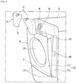
- FIG. 4 is a view illustrating the state in which the fluid storage tank 50 provided in the clothes treatment apparatus 10 of FIG. 2 is separated from the door 30.
- the front frame 311 of the door 30 may be tilted relative to the rear frame 312 by a predetermined angle in the front-and-rear direction.
- the front frame 311 of the door 30 may be opened relative to the rear frame 312 by a predetermined angle in the front-and-rear direction.
- the front frame 311 of the door may be tilted from the rear frame 312 toward the front side of the cabinet 20.
- the upper end of the front frame 311 of the door 30 may be tilted in the front-and-rear direction relative to the upper end of the rear frame 312 to thereby be opened.
- a second grip portion 341 may be provided on the upper end portion of the front surface of the door 30 (i.e. the upper end portion of the front surface of the front frame 311), in order to open the front frame 311 relative to the rear frame 312.
- the second grip portion 341 may be recessed in the upper end of the front surface of the front frame 311.
- the user may separate the fluid storage tank 50 from the front frame 311 by pulling the fluid storage tank 50 upward.
- the fluid storage tank 50 may be separable upward from the front frame 311.
- the user can attach or detach the fluid storage tank 50 to or from the door (i.e. the front frame) in a relaxed position without bending the waist.
- the user may separate the fluid storage tank 50 from the front frame 311, and thereafter may open a cover 52 provided in the fluid storage tank 50 so as to introduce the washing detergent into the fluid storage tank 50.
- the user may open the cover 52 provided on the top of the fluid storage tank 50 so as to introduce the washing detergent into the fluid storage tank 50.
- the user may introduce the washing detergent into the fluid storage tank 50 without separating the fluid storage tank 50 from the front frame 311.
- the second hinge unit 332 may be provided on the bottom portion of the door 30 in the width direction of the door 30.
- the front frame 311 may be rotated in the vertical direction about a horizontal axis X, which extends in the left-and-right direction on the bottom portion of the door 30, so as to be opened relative to the rear frame 312.
- the horizontal axis X represents the axis that extends in the width direction of the door 30 on the bottom portion of the door 30.
- the horizontal axis X may be orthogonal to the above-described vertical axis Y.
- the second hinge unit 332 is provided on the bottom portion of the door 30 and connects the front frame 311 and the rear frame 312 to each other so that the front frame 311 may be tilted by a predetermined angle relative to the rear frame 312.
- the user may separate the fluid storage tank 50 installed to the front frame 311 by upwardly pulling the fluid storage tank from the front frame 311.
- the user may install the fluid storage tank 50 to the front frame 311 by downwardly pushing the fluid storage tank 50 toward the front frame 311, which has been opened away from the rear frame 312.
- the user may introduce the washing detergent into the fluid storage tank 50 after opening only the front frame 311 relative to the rear frame 312, or may separate the fluid storage tank 50 for easy maintenance and repair thereof.
- the frame unit 310 when viewed from the front side of the cabinet 20, the frame unit 310 may have a rectangular shape and the glass unit 320 may have a circular shape.
- one side surface of the fluid storage tank 50 may be placed on the installation surface 353 provided on the installation portion 350 of the door 30.
- the installation surface 353 may be curved so as to have the same shape as the outer circumference of the glass unit 320 of the door 30.
- the side surface of the fluid storage tank 50 that is placed over the installation surface 353 may have a shape corresponding to the shape of the outer circumference of the glass unit 320.
- the fluid storage tank 50 may have a curved surface portion 53 having a shape corresponding to the shape of the outer circumference of the glass unit 320.
- the installation surface 353 may be upwardly convexly formed, and the curved surface portion 53 of the fluid storage tank 50 may be upwardly concavely formed.
- FIG. 5 is a perspective view of a clothes treatment apparatus according to another embodiment of the present invention
- FIG. 6 is a view illustrating the state in which the fluid storage tank provided in the clothes treatment apparatus of FIG. 5 is separated from the door.
- the clothes treatment apparatus 10 includes the cabinet 20 defining the external appearance of the apparatus, the drum 80, which is rotatably installed in the cabinet 20 and accommodates an object to be treated (i.e. a washing object), and the door 30 installed on the cabinet 20.
- the cabinet 20 defining the external appearance of the apparatus
- the drum 80 which is rotatably installed in the cabinet 20 and accommodates an object to be treated (i.e. a washing object)
- the door 30 installed on the cabinet 20.
- the drum 80 may be provided with one or more lifters 81 to lift and drop laundry during rotation of the drum 80, and the lifters 81 may be applied to the clothes treatment apparatus of the above-described embodiment of the present invention.
- the hinge unit 331 may be provided between the door 30 and the cabinet 20 so as to be installed along the vertical axis Y.
- the door 30 may be rotated leftward or rightward relative to the cabinet 20 about the hinge unit 331.
- At least one fluid storage tank 50 may be separably installed to the door 30 and may store a washing detergent to be ejected into the cabinet 20 of the clothes treatment apparatus 10.
- the present embodiment differs from the embodiment of the present invention described above with reference to FIGs. 2 to 4 in terms of the structure of the door 30 to which the fluid storage tank 50 is installed.
- the fluid storage tank 50 is installed to the door 30 and is connected to the pump 60.
- one end of the tube 70 is connected to the connection hole 51 formed in the lower end of the fluid storage tank 50, and the other end of the tube 70 may be installed to the frame unit 310 of the door 30 so as to eject the washing detergent toward the convex portions 321, 322 and 323 of the glass unit 320 (i.e. the upper sloped surface 321).
- cover 52 may be provided on the upper end of the fluid storage tank 50, and the user may introduce the washing detergent into the fluid storage tank 50 after opening the cover 52.
- the fluid storage tank 50 may be formed of a transparent material.
- the fluid storage tank 50 may be installed to the door 30 so that one surface of the fluid storage tank 50 is exposed outward (i.e. to the user) when the door 30 is opened.
- the user may easily check the amount of washing detergent stored in the fluid storage tank 50.
- the door 30 is provided with only one hinge unit 331. That is, the door 30 may be rotated about the hinge unit 331 to thereby be opened away from the cabinet 20.
- both the frame unit 310 of the door 30 and the glass unit 320 provided in the center of the frame unit 310 have a circular shape.
- the installation portion 350 for the installation of the fluid storage tank 50 may be provided on the rear portion of the door 30 (on the rear portion of the frame unit 310).
- the fluid storage tank 50 may be installed to the installation portion 350 of the door 30 so as to be upwardly separable from the door 30.
- the installation portion 350 may be recessed to have a shape corresponding to the shape of the fluid storage tank 50.
- the fluid storage tank 50 has the curved surface portion 53 having a shape corresponding to the shape of the outer circumference of the glass unit 320, which is the same as in the above-described embodiment of the present invention.
- the installation portion 350 may be provided with the installation surface 353, which is curved in the same manner as the outer circumference of the glass unit 320, and the fluid storage tank 50 may be placed over the installation surface 353.
- the curved surface portion 53 of the fluid storage tank 50 has a shape corresponding to the shape of the curved installation surface 353, the space in the frame unit 310 of the door 30 may be efficiently used.
- the user needs to first open the door 30 in order to separate the fluid storage tank 50 from the door 30.
- FIG. 7 is a block diagram for explaining a method of controlling the ejection of the detergent, stored in the fluid storage tank, into the clothes treatment apparatus.
- the clothes treatment apparatus 10 may further include the controller 90.
- the controller 90 may be electrically connected to the operating unit 40, a memory 95, and the pump 60.
- controller 90 may be configured to drive the pump 60 based on a command input to the operating unit 40 by the user.
- the controller 90 may be configured to differently control the pump 60 depending on a user input mode and an automatic control mode.
- the user may directly input the amount of washing detergent to be introduced into the clothes treatment apparatus 10 via the operating unit 40.
- the amount of clothes to be washed and a desired course may be input via the operating unit 40.
- the controller 90 may adjust the pressure of the pump 60 and/or the driving time of the pump 60 based on the user input indicating the amount of washing detergent.
- the pressure of the pump 60 and/or the driving time of the pump 60 depending on the amount of washing detergent may be stored in advance in the memory 95.
- the controller 90 may control the pump 60 so that the washing detergent accommodated in the two fluid storage tanks 50 is introduced into the clothes treatment apparatus 10 at the same time.
- controller 90 may control the pump 60 so that the washing detergent accommodated in the two fluid storage tanks 50 is selectively introduced into the clothes treatment apparatus 10.
- the user may input at least one of a desired course and the amount of clothes to be washed via the operating unit 40. That is, the user may not need to input the amount of washing detergent to be introduced into the clothes treatment apparatus 10.
- the controller 90 may determine the amount of washing detergent to be introduced into the clothes treatment apparatus 10 based on at least one piece of information selected from among the course and the amount of clothes to be washed, which are input by the user.
- controller 90 may adjust the pressure of the pump 60 and/or the driving time of the pump 60 based on the determined amount of clothes to be washed.
- the amount of washing detergent depending on the amount of the clothes to be washed and the course may be stored in advance in the memory 95.
- the pressure of the pump 60 and/or the driving time of the pump 60 may also be stored in advance in the memory 95.
- both of the fluid storage tanks 50 may accommodate washing detergent for use in a washing cycle.
- the controller 90 may control the pump 60 so that the washing detergent accommodated in the two fluid storage tanks 50 is simultaneously or selectively introduced into the clothes treatment apparatus 1.
- one of the two fluid storage tanks 50 may accommodate the washing detergent for use in a washing cycle, and the other one may accommodate a softener for use in a rinsing cycle.
- the controller 90 may control the pump 60 so that the pump 60 applies pressure to the fluid storage tank 50, in which the washing detergent is accommodated, during the washing cycle.
- the controller 90 may control the pump 60 so that the pump 60 applies pressure to the fluid storage tank 50, in which the softener is accommodated, during the rinsing cycle.
- an appropriate amount of washing detergent stored in the fluid storage tank 50 may be introduced to the clothes treatment apparatus 10 in a simplified manner via manipulation of the operating unit 40.
- the configuration in which the pump 60 is controlled by the controller 90 so as to apply pressure to the two fluid storage tanks 60 simultaneously or selectively is a known technology and is also a technology that may be clearly understood by those skilled in the art, and thus a detailed description thereof will not be described.
- the user may open the door 30 and check the amount of washing detergent stored in the fluid storage tank 50, in order to replenish the washing detergent in the fluid storage tank 50.
- the user may frequently check the amount of washing detergent stored in the fluid storage tank 50.
Abstract
Description
- The present invention relates to a clothes treatment apparatus (in particular, a washing machine), and more particularly, to a clothes treatment apparatus, which includes a fluid storage tank in which a detergent or a fabric softener may be stored in advance, whereby it is not necessary to replenish the detergent or the fabric softener every time the user operates the clothes treatment apparatus.
- Generally, clothes treatment apparatuses may include, for example, a washing machine, a drying machine, and a so-called styler, and the washing machine may include a drying function.
- The washing machine may be broadly divided into a pulsator-type washing machine, in which a drum is vertically upright (i.e. a laundry opening is located in the upper side of a cabinet), and a drum-type washing machine, in which a drum is oriented horizontally (i.e. a laundry opening is located in the front side of a cabinet).
- Such a clothes treatment apparatus may be operated via manipulation of an operating unit, which is provided in the cabinet of the laundry treatment apparatus, after, for example, an object to be treated and a detergent are introduced into the clothes treatment apparatus.
- Recently, with regard to the use of the clothes treatment apparatus, study on clothes treatment apparatuses capable of minimizing user inconvenience and attaining a cleaner and simpler external appearance is underway.
-
FIG. 1 schematically illustrates a conventional clothes treatment apparatus. - Referring to
FIG. 1 , the conventionalclothes treatment apparatus 1 includes acabinet 2 defining the external appearance of the apparatus, adoor 3 configured to open or close thecabinet 2, an operating unit 4 configured to operate theclothes treatment apparatus 1, and adetergent introduction unit 5 configured to supply at least one of a detergent and a fabric softener into theclothes treatment apparatus 1. - In order to wash clothes using the
clothes treatment apparatus 1, a user needs to introduce the clothes into thecabinet 2 in the opened state of thedoor 3, and then to open thedetergent introduction unit 5 so as to introduce at least one of a detergent and a fabric softener. - That is, the user needs to open the
detergent introduction unit 5 so as to introduce an appropriate amount of detergent and/or fabric softener every time the user operates theclothes treatment apparatus 1. Of course, only one of the detergent and/or the fabric softener may be introduced depending on, for example, the washing course that is selected. - The conventional
clothes treatment apparatus 1 described above is problematic or inconvenient because the user needs to open thedetergent introduction unit 5 and directly introduce the detergent and/or the fabric softener every time the user operates theclothes treatment apparatus 1. - In addition, it is problematic or inconvenient to directly adjust an appropriate amount of detergent depending on, for example, the course selected by the user, the type of clothes to be treated, and the amount of clothes, prior to introducing the detergent into the
detergent introduction unit 5. - In addition, because the
detergent introduction unit 5 is provided at the exterior of thecabinet 2, the external appearance of theclothes treatment apparatus 1 does not have a neat appearance. - One object of the present invention is to overcome a problem or an inconvenience in that a user needs to directly introduce a detergent and/or a fabric softener into a clothes treatment apparatus (or a detergent introduction unit) every time the user operates the clothes treatment apparatus.
- That is, another object of the present invention is to provide a clothes treatment apparatus, which may include a fluid storage tank, which is provided so as to be attachable to or detachable from a door of the clothes treatment apparatus, so that the fluid storage tank is filled in advance with a predetermined amount of detergent and/or fabric softener, thereby allowing the clothes treatment apparatus to be operated multiple times.
- In addition, another object of the present invention is to provide a clothes treatment apparatus, which may allow an appropriate amount of detergent to be introduced manually or automatically into the clothes treatment apparatus from a fluid storage tank depending on, for example, the course selected by a user, the type of clothes to be treated, and the amount of clothes.
- In addition, a further object of the present invention is provide a clothes treatment apparatus having a cleaner external appearance by removing a detergent introduction unit, which has conventionally been provided on the outer surface of a cabinet of a clothes treatment apparatus.
- According to one aspect of the present application to achieve the objects described above, there is provided a clothes treatment apparatus including a cabinet defining an external appearance of the apparatus, a drum rotatably installed in the cabinet and configured to accommodate an object to be treated, and a door installed on a front side of the cabinet, wherein the door includes at least one separable fluid storage tank configured to store at least one of a detergent and a fabric softener.
- The door may include a frame unit and a transparent glass unit provided in a center of the frame unit, and the fluid storage tank may be provided on the frame unit.
- The fluid storage tank may be formed of a transparent material, and, when the door is opened, a rear surface of the fluid storage tank may be exposed.
- The door may be provided with an installation portion for installation of the fluid storage tank, the installation portion having a shape corresponding to a shape of the fluid storage tank.
- The door may include a front frame facing the front side of the cabinet and a rear frame opposite the front frame, and the installation portion may be provided on the front frame.
- The door may be provided on one side portion thereof with a first hinge unit in a height direction of the door so that the door is rotated leftward or rightward relative to the cabinet, and the door may be provided on a bottom portion thereof with a second hinge unit in a width direction of the door so that the front frame is titled in a front-and-rear direction by a predetermined angle relative to the rear frame.
- When the front frame is tilted forward by the predetermined angle relative to the rear frame, an upper portion of the fluid storage tank may be exposed outward.
- The fluid storage tank may be upwardly separable from the front frame in a state in which the front frame is tilted forward by the predetermined angle relative to the rear frame.
- The fluid storage tank may be upwardly separable from the door in a state in which the door is opened away from the cabinet.
- The fluid storage tank may be connected to a tube, the tube serving to guide the detergent or the fabric softener stored in the fluid storage tank to an inside of the cabinet.
- The glass unit may include a convex portion protruding toward the inside of the cabinet, and the tube may have one end connected to the fluid storage tank, and a remaining end installed to the frame unit so as to eject the detergent or the fabric softener toward the convex portion from an upper side of the convex portion.
- The one end of the tube may be connected to a lower end of the fluid storage tank.
- The clothes treatment apparatus may further include a pump configured to eject the detergent or the fabric softener stored in the fluid storage tank to an inside of the cabinet.
- The door may be provided with two fluid storage tanks separated from each other, and the pump may be located between the two fluid storage tanks.
- The frame unit may have a rectangular shape and the glass unit has a circular shape when viewed from the front side of the cabinet, and the fluid storage tank may include a curved surface portion having a shape corresponding to a shape of an outer circumference of the glass unit.
- Each of the frame unit and the glass unit may have a circular shape when viewed from the front side of the cabinet, and the fluid storage tank may include a curved surface portion having a shape corresponding to a shape of an outer circumference of the glass unit.
- According to the present invention, because a fluid storage tank is filled in advance with a predetermined amount of detergent and/or fabric softener, which may be sufficient to operate a clothes treatment apparatus multiple times, inconvenience related to the introduction of a detergent and/or a fabric softener into the clothes treatment apparatus every time the clothes treatment apparatus is operated is eliminated.
- In addition, according to the present invention, an appropriate amount of detergent depending on, for example, the course selected by a user, the type of clothes to be treated, and the amount of clothes may be introduced manually or automatically into the clothes treatment apparatus from the fluid storage tank.
- In addition, according to the present invention, because one surface of the fluid storage tank is exposed outward when a door is opened, the user may easily check the amount of detergent stored in the fluid storage tank.
- In addition, according to the present invention, because the fluid storage tank is separable from the door, the user may easily fill the fluid storage tank with the detergent or the fabric softener.
- In addition, according to the present invention, because the fluid storage tank is installed inside a door frame, deterioration in the external appearance of the clothes treatment apparatus may be prevented, and the space inside the door frame may be efficiently used.
- In addition, according to the present invention, the clothes treatment apparatus may achieve a cleaner external appearance, owing to the removal of a detergent introduction unit, which has conventionally been provided on the outer surface of a cabinet in a clothes treatment apparatus.
-
-
FIG. 1 is a view illustrating a conventional clothes treatment apparatus. -
FIG. 2 is a perspective view of a clothes treatment apparatus according to an embodiment of the present invention. -
FIG. 3(a) is a view illustrating the state before a front frame of a door is tilted in the clothes treatment apparatus ofFIG. 2 , andFIG. 3(b) is a view illustrating the state in which the front frame of the door is tilted in the clothes treatment apparatus ofFIG. 2 . -
FIG. 4 is a view illustrating the state in which a fluid storage tank provided in the clothes treatment apparatus ofFIG. 2 is separated from the door. -
FIG. 5 is a perspective view of a clothes treatment apparatus according to another embodiment of the present invention. -
FIG. 6 is a view illustrating the state in which the fluid storage tank provided in the clothes treatment apparatus ofFIG. 5 is separated from the door. -
FIG. 7 is a block diagram for explaining a method of controlling the ejection of a detergent, stored in the fluid storage tank, into the clothes treatment apparatus. - Hereinafter, exemplary embodiments of the present invention to concretely realize the objects described above will be described with reference to the accompanying drawings. Although a clothes treatment apparatus, which will be described below, may include a washing machine, a drying machine, or a so-called styler, a washing machine including a drying function will be mainly described.
- Meanwhile, a damping structure, a water supply structure, a drainage structure, and the like, which may be provided inside the clothes treatment apparatus, are the same as or similar to corresponding structures of a conventional clothes treatment apparatus, and thus in the following description of the present invention, a detailed description related to general structures of the conventional clothes treatment apparatus will be omitted.
-
FIG. 2 is a perspective view of aclothes treatment apparatus 10 according to an embodiment of the present invention. Specifically,FIG. 2 is a perspective view illustrating the opened state of adoor 30 in theclothes treatment apparatus 10 according to the embodiment of the present invention. - Referring to
FIG. 2 , theclothes treatment apparatus 10 according to the embodiment of the present invention includes acabinet 20 defining the external appearance of the apparatus, adrum 80, which is rotatably installed in thecabinet 20 and accommodates an object to be treated (i.e. a laundry or a washing object), and adoor 30 installed on thecabinet 20. - A tub (not illustrated) may be further disposed inside the
cabinet 20 so as to surround thedrum 80 in order to accommodate wash water. - The
cabinet 20 may be provided with anoperating unit 40 to operate theclothes treatment apparatus 10. - The
operating unit 40 takes the form of a rotatable rotary knob, and a user may power on theclothes treatment apparatus 10 using theoperating unit 40. In addition, the user may select, for example, a desired clothes treatment course by rotating theoperating unit 40, and then may operate the clothes treatment apparatus. - At this time, there may be clothes treatment courses including, for example, a standard washing course, a baby clothes course, a boiling course, a speedy wash course, a lingerie course, and a bedding course. In addition, for example, the number of rinsing operations in a rinsing course, the strength of dehydration of a dehydration course, and the temperature of wash water may be set via the
operating unit 40. - An
opening 21 is formed in the front portion of thecabinet 20, and the object to be washed (e.g. clothes) may be placed into thedrum 80 through theopening 21. Thisopening 21 may be opened or closed by thedoor 30. - For example, the
door 30 may be formed on one side portion of thedoor 30 so as to be rotated leftward or rightward about a vertical axis Y, which extends in the vertical direction, thereby opening or closing theopening 21. - That is, the
door 30 may be provided on one side portion thereof with afirst hinge unit 331 along the height direction of thedoor 30 so that thedoor 30 is rotated leftward or rightward relative to thecabinet 20. - More specifically, in order to rotate the door 30 (i.e. in order to open or close the door 30), the
first hinge unit 331 may be provided between thedoor 30 and thecabinet 20 so as to be installed along the vertical axis Y. - Accordingly, the
door 30 may be rotated leftward or rightward relative to thecabinet 20 about thefirst hinge unit 331. - In addition, the
door 30 may be provided on the other side portion thereof with afirst grip portion 340, which is used to open or close thedoor 30. Thefirst grip portion 340 may be recessed in the other side portion of thedoor 30 in the width direction. - Meanwhile, at least one
fluid storage tank 50 may be separably installed to thedoor 30 and may be used to store at least one of a detergent and a fabric softener (hereinafter referred to as a "washing detergent"). - The
fluid storage tank 50, which will be described below in detail, may store a predetermined amount of washing detergent. The amount of washing detergent stored in thefluid storage tank 50 may be sufficient to operate the clothes treatment apparatus multiple times (e.g. 5 times to 10 times). - For example, the
fluid storage tank 50 may be formed to have a predetermined volume. - At this time, the amount of washing detergent stored in the
fluid storage tank 50 may be within a range from approximately 1 liter to 3 liters. - Meanwhile, in the case where two separated
fluid storage tanks 50 are provided on onedoor 30, the amount of washing detergent stored in eachfluid storage tank 50 having a predetermined volume may be within a range from approximately 0.5 liter to 1.5 liters. - Specifically, the
door 30 includes aframe unit 310, and aglass unit 320 provided in theframe unit 310. At this time, thefluid storage tank 50 may be attached to theframe unit 310. - For example, the
glass unit 320 may be formed of a transparent material in order to allow the inside of thedrum 80 of theclothes treatment apparatus 10 to be visible from outside theclothes treatment apparatus 10, and theglass unit 320 may be provided in the center of theframe unit 310. - In addition, the
glass unit 320 includesconvex portions cabinet 20. At this time, theconvex portions sloped surface 321, which is downwardly inclined toward the inside of thecabinet 20, a lower slopedsurface 322, which is upwardly inclined toward the inside of thecabinet 20, and aboundary portion 323 between the upper slopedsurface 321 and the lower slopedsurface 322. - In addition, the
fluid storage tank 50 may be separably installed to theframe unit 310 of thedoor 30. - Accordingly, in order to install the
fluid storage tank 50 to thedoor 30, no separate space may be necessary, and the remaining space in theframe unit 310 of thedoor 30 may be efficiently used. - The
fluid storage tank 50 may be formed of a transparent material. In addition, thefluid storage tank 50 may be installed to thedoor 30 so that one surface of thefluid storage tank 50 is exposed outward (i.e. to the user) when thedoor 30 is opened. - For example, defining the portion of the
cabinet 20 to which thedoor 30 is installed as the front portion and the opposite portion as the rear portion, thefluid storage tank 50 may be installed to thedoor 30 so that the rear surface of thefluid storage tank 50 is exposed to the user when thedoor 30 is opened. - Accordingly, when the
door 30 is opened away from thecabinet 20, the user may easily check the amount of washing detergent stored in thefluid storage tank 50. - In addition, the
door 30 may be provided with aninstallation portion 350 for the installation of thefluid storage tank 50. - The
installation portion 350 may be recessed and may have a shape corresponding to the shape of thefluid storage tank 50. - In addition, the
installation portion 350 is provided with aninstallation surface 353, and at least one surface of thefluid storage tank 50 is placed on theinstallation surface 353. - More specifically, the
frame unit 310 of thedoor 30 may include afront frame 311, which faces the front side of thecabinet 20, and arear frame 312, which is coupled to thefront frame 311 with a predetermined space therebetween. - At this time, the
installation portion 350 may be provided on thefront frame 311. In addition, a portion of therear frame 312 at which thefluid storage tank 50 is disposed is cut away. - That is, the front surface of the
fluid storage tank 50 is covered with thefront frame 311, whereas the rear surface of thefluid storage tank 50 is exposed outward when thedoor 30 is opened. - Accordingly, when the
door 30 is opened, the user may easily check the amount of washing detergent stored in thefluid storage tank 50. - In the state in which the
door 30 is rotated about the vertical axis Y to thereby be opened, thefluid storage tank 50 may be separated from thefront frame 311. - In addition, the
fluid storage tank 50 has a thickness that is equal to or less than the sum of thicknesses of thefront frame 311 and therear frame 312. Thus, even if thefluid storage tank 50 is installed on thedoor 30, the thickness of thedoor 30 is not increased. - That is, the
fluid storage tank 50 may be installed in an empty space inside theframe unit 310 of thedoor 30 that is defined by the thickness of thedoor 30. - Meanwhile, the
fluid storage tank 50 may be connected to atube 70, which serves to guide the washing detergent stored in thefluid storage tank 50 to the inside of the cabinet 20 (i.e. to the inside of the drum 80). - Accordingly, the washing detergent stored in the
fluid storage tank 50 may be introduced into thecabinet 20 through thetube 70. - Specifically, one
end 71 of thetube 70 may be connected to thefluid storage tank 50, and theother end 72 of thetube 70 may be installed to theframe unit 310 of thedoor 30 so as to eject the washing detergent toward theconvex portions glass unit 320, from the upper side of theconvex portions - In addition, an ejection nozzle may be provided at the
other end 72 of thetube 70. - Accordingly, the washing detergent ejected through the
other end 72 of thetube 70 may be guided to the inside of theclothes treatment apparatus 10 along the surface of theconvex portions - That is, the washing detergent, ejected through the ejection nozzle provided at the
other end 72 of thetube 70, may flow down along the upper slopedsurface 321 of theconvex portion clothes treatment apparatus 10. - Generally, because water supplied into the clothes treatment apparatus is ejected toward the inner surface of the
door 30, the washing detergent, which flows down along the upper slopedsurface 321, may easily flow down to the inside of theclothes treatment apparatus 10 due to the water ejected toward the inner surface of thedoor 30. - Meanwhile, one end of the
tube 70 may be connected to the lower end of thefluid storage tank 50. - This serves not only to allow the washing detergent stored in the
fluid storage tank 50 to be easily discharged through thetube 70 due to gravity, but also to allow the washing detergent to be efficiently supplied even in the situation in which the amount of washing detergent inside thefluid storage tank 50 is not great. - In the present embodiment, one end of the
tube 70 may be connected to aconnection hole 51 formed in the lower end of thefluid storage tank 50. - Meanwhile, the
clothes treatment apparatus 10 according to the present embodiment may further include apump 60, which serves to eject the washing detergent stored in thefluid storage tank 50 to the inside of thecabinet 20. - For example, the
pump 60 may be connected to one side of thefluid storage tank 50. In the case where a plurality offluid storage tanks 50 is provided, thepump 60 may be connected to each of thefluid storage tanks 50. - The
pump 60 may apply pressure to the inside of thefluid storage tank 50 so that the washing detergent in thefluid storage tank 50 is ejected to the inside of thecabinet 20 based on the pressure and/or the time depending on a user command, or based on a preset pressure and/or time depending on a selected course. - Meanwhile, in the present embodiment, two
fluid storage tanks 50 may be separately provided on thedoor 30, and thepump 60 may be located between the twofluid storage tanks 50. - For example, the
pump 60 may be disposed on thefront frame 311 of thedoor 30 above theglass unit 320, and the twofluid storage tanks 50 may be disposed respectively at opposite sides of thepump 60. - At this time, each of the two
fluid storage tanks 50 may be connected to thepump 60. - In addition, the two
fluid storage tanks 50 may be installed at the upper left and right corner portions of thedoor 30. - At this time, the
pump 60 may be connected to each of the twofluid storage tanks 50. - Hereinafter, a structure for attaching or detaching the
fluid storage tank 50 to or from thedoor 30 and a method of filling thefluid storage tank 50 with the washing detergent will be described with reference toFIGs. 3(a) and 3(b) andFIG. 4 . -
FIG. 3(a) is a view illustrating the state before thefront frame 311 of thedoor 30 is tilted in theclothes treatment apparatus 10 ofFIG. 2 , andFIG. 3(b) is a view illustrating the state in which thefront frame 311 of thedoor 30 is tilted in theclothes treatment apparatus 10 ofFIG. 2 . - In addition,
FIG. 4 is a view illustrating the state in which thefluid storage tank 50 provided in theclothes treatment apparatus 10 ofFIG. 2 is separated from thedoor 30. - First, referring to
FIGs. 3(a) and 3(b) , when thedoor 30 is closed relative to the cabinet 20 (FIG. 3(a) ), thefront frame 311 of thedoor 30 may be tilted relative to therear frame 312 by a predetermined angle in the front-and-rear direction. - That is, in the state in which the
door 30 is closed relative to the cabinet 20 (FIG. 3(a) ), thefront frame 311 of thedoor 30 may be opened relative to therear frame 312 by a predetermined angle in the front-and-rear direction. - For example, in the state in which the
rear frame 312 of thedoor 30 is closed relative to thecabinet 20, thefront frame 311 of the door may be tilted from therear frame 312 toward the front side of thecabinet 20. - More specifically, by a
second hinge unit 332 provided on the bottom portion of thedoor 30, which will be described below, the upper end of thefront frame 311 of thedoor 30 may be tilted in the front-and-rear direction relative to the upper end of therear frame 312 to thereby be opened. - At this time, a
second grip portion 341 may be provided on the upper end portion of the front surface of the door 30 (i.e. the upper end portion of the front surface of the front frame 311), in order to open thefront frame 311 relative to therear frame 312. - In addition, the
second grip portion 341 may be recessed in the upper end of the front surface of thefront frame 311. - When the upper end of the
front frame 311 of thedoor 30 is opened, the upper portion of thefluid storage tank 50 installed to thefront frame 311 is exposed outward. - That is, when the
front frame 311 is tilted forward by a predetermined angle relative to therear frame 312, the upper portion of thefluid storage tank 50 is exposed outward. - At this time, the user may separate the
fluid storage tank 50 from thefront frame 311 by pulling thefluid storage tank 50 upward. - That is, in the state in which the
front frame 311 is tilted forward by a predetermined angle relative to therear frame 312, thefluid storage tank 50 may be separable upward from thefront frame 311. - Accordingly, the user can attach or detach the
fluid storage tank 50 to or from the door (i.e. the front frame) in a relaxed position without bending the waist. - In addition, in the state in which the upper end of the
front frame 311 is opened by tilting thefront frame 311, the user may separate thefluid storage tank 50 from thefront frame 311, and thereafter may open acover 52 provided in thefluid storage tank 50 so as to introduce the washing detergent into thefluid storage tank 50. - In addition, in the state in which the upper end of the
front frame 311 of thedoor 30 is opened, the user may open thecover 52 provided on the top of thefluid storage tank 50 so as to introduce the washing detergent into thefluid storage tank 50. - That is, the user may introduce the washing detergent into the
fluid storage tank 50 without separating thefluid storage tank 50 from thefront frame 311. - In addition, referring to
FIG. 4 , in order to allow thefront frame 311 of thedoor 30 to be opened forward relative to therear frame 312, thesecond hinge unit 332 may be provided on the bottom portion of thedoor 30 in the width direction of thedoor 30. - For example, the
front frame 311 may be rotated in the vertical direction about a horizontal axis X, which extends in the left-and-right direction on the bottom portion of thedoor 30, so as to be opened relative to therear frame 312. - That is, the horizontal axis X represents the axis that extends in the width direction of the
door 30 on the bottom portion of thedoor 30. In addition, the horizontal axis X may be orthogonal to the above-described vertical axis Y. - In addition, the
second hinge unit 332 is provided on the bottom portion of thedoor 30 and connects thefront frame 311 and therear frame 312 to each other so that thefront frame 311 may be tilted by a predetermined angle relative to therear frame 312. - Accordingly, after the user opens the
front frame 311 relative to therear frame 312, the user may separate thefluid storage tank 50 installed to thefront frame 311 by upwardly pulling the fluid storage tank from thefront frame 311. - Conversely, the user may install the
fluid storage tank 50 to thefront frame 311 by downwardly pushing thefluid storage tank 50 toward thefront frame 311, which has been opened away from therear frame 312. - In this way, even though the user does not open the
door 30 from thecabinet 20, the user may introduce the washing detergent into thefluid storage tank 50 after opening only thefront frame 311 relative to therear frame 312, or may separate thefluid storage tank 50 for easy maintenance and repair thereof. - Meanwhile, referring to
FIGs. 1 and4 , when viewed from the front side of thecabinet 20, theframe unit 310 may have a rectangular shape and theglass unit 320 may have a circular shape. - In addition, when the
fluid storage tank 50 is coupled to thedoor 30, one side surface of thefluid storage tank 50 may be placed on theinstallation surface 353 provided on theinstallation portion 350 of thedoor 30. - At this time, the
installation surface 353 may be curved so as to have the same shape as the outer circumference of theglass unit 320 of thedoor 30. - In addition, the side surface of the
fluid storage tank 50 that is placed over theinstallation surface 353 may have a shape corresponding to the shape of the outer circumference of theglass unit 320. - That is, the
fluid storage tank 50 may have acurved surface portion 53 having a shape corresponding to the shape of the outer circumference of theglass unit 320. - For example, the
installation surface 353 may be upwardly convexly formed, and thecurved surface portion 53 of thefluid storage tank 50 may be upwardly concavely formed. - Accordingly, with the
curved surface portion 53 of thefluid storage tank 50, as much of the limited space inside theframe unit 310 of thedoor 30 as possible may be used as efficiently as possible. - Hereinafter, a clothes treatment apparatus according to another embodiment of the present invention will be described with reference to
FIGs. 5 and6 . -
FIG. 5 is a perspective view of a clothes treatment apparatus according to another embodiment of the present invention, andFIG. 6 is a view illustrating the state in which the fluid storage tank provided in the clothes treatment apparatus ofFIG. 5 is separated from the door. - Hereinafter, in the description of the clothes treatment apparatus according to the other embodiment of the present invention, made with reference to
FIGs. 5 and6 , components that are the same as or corresponding to those of the clothes treatment apparatus described with reference toFIGs. 2 to 4 will be designated by the same reference numerals. In addition, differences from the clothes treatment apparatus described with reference toFIGs. 2 to 4 will be described below in detail. - Referring to
FIGs. 5 and6 , theclothes treatment apparatus 10 according to the other embodiment of the present invention includes thecabinet 20 defining the external appearance of the apparatus, thedrum 80, which is rotatably installed in thecabinet 20 and accommodates an object to be treated (i.e. a washing object), and thedoor 30 installed on thecabinet 20. - The
drum 80 may be provided with one ormore lifters 81 to lift and drop laundry during rotation of thedrum 80, and thelifters 81 may be applied to the clothes treatment apparatus of the above-described embodiment of the present invention. - In order to rotate the door 30 (i.e. to open or close the door 30), the
hinge unit 331 may be provided between thedoor 30 and thecabinet 20 so as to be installed along the vertical axis Y. - Accordingly, the
door 30 may be rotated leftward or rightward relative to thecabinet 20 about thehinge unit 331. - Meanwhile, at least one
fluid storage tank 50 may be separably installed to thedoor 30 and may store a washing detergent to be ejected into thecabinet 20 of theclothes treatment apparatus 10. - The present embodiment differs from the embodiment of the present invention described above with reference to
FIGs. 2 to 4 in terms of the structure of thedoor 30 to which thefluid storage tank 50 is installed. - That is, the
fluid storage tank 50 is installed to thedoor 30 and is connected to thepump 60. In addition, one end of thetube 70 is connected to theconnection hole 51 formed in the lower end of thefluid storage tank 50, and the other end of thetube 70 may be installed to theframe unit 310 of thedoor 30 so as to eject the washing detergent toward theconvex portions - In addition, the
cover 52 may be provided on the upper end of thefluid storage tank 50, and the user may introduce the washing detergent into thefluid storage tank 50 after opening thecover 52. - In addition, the
fluid storage tank 50 may be formed of a transparent material. Thefluid storage tank 50 may be installed to thedoor 30 so that one surface of thefluid storage tank 50 is exposed outward (i.e. to the user) when thedoor 30 is opened. - Accordingly, when the
door 30 is opened away from thecabinet 20, the user may easily check the amount of washing detergent stored in thefluid storage tank 50. - Meanwhile, the detailed structure of the
door 30, which will be described below, differs from that in the above-described embodiment of the present invention with reference toFIGs. 2 to 4 . - First, the
door 30 is provided with only onehinge unit 331. That is, thedoor 30 may be rotated about thehinge unit 331 to thereby be opened away from thecabinet 20. - In addition, when viewed from the front side of the
cabinet 20, both theframe unit 310 of thedoor 30 and theglass unit 320 provided in the center of theframe unit 310 have a circular shape. - In addition, the
installation portion 350 for the installation of thefluid storage tank 50 may be provided on the rear portion of the door 30 (on the rear portion of the frame unit 310). - Accordingly, in the state in which the
door 30 is opened away from thecabinet 20, thefluid storage tank 50 may be installed to theinstallation portion 350 of thedoor 30 so as to be upwardly separable from thedoor 30. - In addition, the
installation portion 350 may be recessed to have a shape corresponding to the shape of thefluid storage tank 50. - Here, the
fluid storage tank 50 has thecurved surface portion 53 having a shape corresponding to the shape of the outer circumference of theglass unit 320, which is the same as in the above-described embodiment of the present invention. - That is, the
installation portion 350 may be provided with theinstallation surface 353, which is curved in the same manner as the outer circumference of theglass unit 320, and thefluid storage tank 50 may be placed over theinstallation surface 353. - At this time, because the
curved surface portion 53 of thefluid storage tank 50 has a shape corresponding to the shape of thecurved installation surface 353, the space in theframe unit 310 of thedoor 30 may be efficiently used. - The difference between the embodiment illustrated in
FIGs. 5 and6 and the embodiment illustrated inFIGs. 2 to 4 is that, in the case of the embodiment illustrated inFIGs. 5 and6 , thefluid storage tank 50 is separable from thedoor 30 only when thedoor 30 is opened. - That is, in the embodiment illustrated in
FIGs. 5 and6 , the user needs to first open thedoor 30 in order to separate thefluid storage tank 50 from thedoor 30. - Hereinafter, a control method of ejecting the washing detergent stored in the
fluid storage tank 50 to the inside of theclothes treatment apparatus 10 will be described with reference toFIG. 7 . -
FIG. 7 is a block diagram for explaining a method of controlling the ejection of the detergent, stored in the fluid storage tank, into the clothes treatment apparatus. - All features of a
controller 90 illustrated inFIG. 7 may be applied to the above-described embodiment and the other embodiment of the present invention. - Referring to
FIG. 7 , theclothes treatment apparatus 10 according to the present invention may further include thecontroller 90. - The
controller 90 may be electrically connected to the operatingunit 40, amemory 95, and thepump 60. - In addition, the
controller 90 may be configured to drive thepump 60 based on a command input to the operatingunit 40 by the user. - For example, the
controller 90 may be configured to differently control thepump 60 depending on a user input mode and an automatic control mode. - In the user input mode, the user may directly input the amount of washing detergent to be introduced into the
clothes treatment apparatus 10 via the operatingunit 40. Of course, the amount of clothes to be washed and a desired course may be input via the operatingunit 40. - In this case, the
controller 90 may adjust the pressure of thepump 60 and/or the driving time of thepump 60 based on the user input indicating the amount of washing detergent. - At this time, the pressure of the
pump 60 and/or the driving time of thepump 60 depending on the amount of washing detergent may be stored in advance in thememory 95. - Meanwhile, in the case where the
door 30 is provided with twofluid storage tanks 50, thecontroller 90 may control thepump 60 so that the washing detergent accommodated in the twofluid storage tanks 50 is introduced into theclothes treatment apparatus 10 at the same time. - In addition, the
controller 90 may control thepump 60 so that the washing detergent accommodated in the twofluid storage tanks 50 is selectively introduced into theclothes treatment apparatus 10. - In addition, in the automatic control mode, the user may input at least one of a desired course and the amount of clothes to be washed via the operating
unit 40. That is, the user may not need to input the amount of washing detergent to be introduced into theclothes treatment apparatus 10. - In this case, the
controller 90 may determine the amount of washing detergent to be introduced into theclothes treatment apparatus 10 based on at least one piece of information selected from among the course and the amount of clothes to be washed, which are input by the user. - In addition, the
controller 90 may adjust the pressure of thepump 60 and/or the driving time of thepump 60 based on the determined amount of clothes to be washed. - At this time, the amount of washing detergent depending on the amount of the clothes to be washed and the course may be stored in advance in the
memory 95. In addition, the pressure of thepump 60 and/or the driving time of thepump 60 may also be stored in advance in thememory 95. - In addition, in both the user input mode and the automatic control mode, in the case where the
door 30 is provided with twofluid storage tanks 50, the following two cases may be basically considered. - First, both of the
fluid storage tanks 50 may accommodate washing detergent for use in a washing cycle. In this case, thecontroller 90 may control thepump 60 so that the washing detergent accommodated in the twofluid storage tanks 50 is simultaneously or selectively introduced into theclothes treatment apparatus 1. - Second, one of the two
fluid storage tanks 50 may accommodate the washing detergent for use in a washing cycle, and the other one may accommodate a softener for use in a rinsing cycle. - In this case, the
controller 90 may control thepump 60 so that thepump 60 applies pressure to thefluid storage tank 50, in which the washing detergent is accommodated, during the washing cycle. In addition, thecontroller 90 may control thepump 60 so that thepump 60 applies pressure to thefluid storage tank 50, in which the softener is accommodated, during the rinsing cycle. - According to the present invention described above, even if the user does not introduce the washing detergent every time the user operates the
clothes treatment apparatus 10, an appropriate amount of washing detergent stored in thefluid storage tank 50 may be introduced to theclothes treatment apparatus 10 in a simplified manner via manipulation of the operatingunit 40. - As described above, the configuration in which the
pump 60 is controlled by thecontroller 90 so as to apply pressure to the twofluid storage tanks 60 simultaneously or selectively is a known technology and is also a technology that may be clearly understood by those skilled in the art, and thus a detailed description thereof will not be described. - Meanwhile, after operating the
clothes treatment apparatus 10 multiple times, the user may open thedoor 30 and check the amount of washing detergent stored in thefluid storage tank 50, in order to replenish the washing detergent in thefluid storage tank 50. - At this time, because the opening of the
door 30 is performed every time theclothes treatment apparatus 10 is used, the user may frequently check the amount of washing detergent stored in thefluid storage tank 50. - This is included in the content of the specification.
Claims (16)
- A clothes treatment apparatus comprising:a cabinet defining an external appearance of the apparatus;a drum rotatably installed in the cabinet and configured to accommodate an object to be treated; anda door installed on a front side of the cabinet,wherein the door includes at least one separable fluid storage tank configured to store at least one of a detergent and a fabric softener.
- The apparatus according to claim 1, wherein the door includes a frame unit and a transparent glass unit provided in a center of the frame unit, and
wherein the fluid storage tank is provided on the frame unit. - The apparatus according to claim 1, wherein the fluid storage tank is formed of a transparent material, and
wherein, when the door is opened, a rear surface of the fluid storage tank is exposed. - The apparatus according to claim 1, wherein the door is provided with an installation portion for installation of the fluid storage tank, the installation portion having a shape corresponding to a shape of the fluid storage tank.
- The apparatus according to claim 4, wherein the door includes a front frame facing the front side of the cabinet and a rear frame opposite the front frame, and
wherein the installation portion is provided on the front frame. - The apparatus according to claim 5, wherein the door is provided on one side portion thereof with a first hinge unit in a height direction of the door so that the door is rotated leftward or rightward relative to the cabinet, and
wherein the door is provided on a bottom portion thereof with a second hinge unit in a width direction of the door so that the front frame is titled in a front-and-rear direction by a predetermined angle relative to the rear frame. - The apparatus according to claim 6, wherein, when the front frame is tilted forward by the predetermined angle relative to the rear frame, an upper portion of the fluid storage tank is exposed outward.
- The apparatus according to claim 7, wherein the fluid storage tank is upwardly separable from the front frame in a state in which the front frame is tilted forward by the predetermined angle relative to the rear frame.
- The apparatus according to claim 4, wherein the fluid storage tank is upwardly separable from the door in a state in which the door is opened away from the cabinet.
- The apparatus according to claim 2, wherein the fluid storage tank is connected to a tube, the tube serving to guide the detergent or the fabric softener stored in the fluid storage tank to an inside of the cabinet.
- The apparatus according to claim 10, wherein the glass unit includes a convex portion protruding toward the inside of the cabinet, and
wherein the tube has one end connected to the fluid storage tank, and a remaining end installed to the frame unit so as to eject the detergent or the fabric softener toward the convex portion from an upper side of the convex portion. - The apparatus according to claim 11, wherein the one end of the tube is connected to a lower end of the fluid storage tank.
- The apparatus according to claim 1, further comprising a pump configured to eject the detergent or the fabric softener stored in the fluid storage tank to an inside of the cabinet.
- The apparatus according to claim 13, wherein the door is provided with two fluid storage tanks separated from each other, and
wherein the pump is located between the two fluid storage tanks. - The apparatus according to claim 2, wherein the frame unit has a rectangular shape and the glass unit has a circular shape when viewed from the front side of the cabinet, and
wherein the fluid storage tank includes a curved surface portion having a shape corresponding to a shape of an outer circumference of the glass unit. - The apparatus according to claim 2, wherein each of the frame unit and the glass unit has a circular shape when viewed from the front side of the cabinet, and
wherein the fluid storage tank includes a curved surface portion having a shape corresponding to a shape of an outer circumference of the glass unit.
Applications Claiming Priority (2)
| Application Number | Priority Date | Filing Date | Title |
|---|---|---|---|
| KR1020140130811A KR102254890B1 (en) | 2014-09-30 | 2014-09-30 | Laundry treating apparatus |
| PCT/KR2015/009996 WO2016052907A1 (en) | 2014-09-30 | 2015-09-23 | Clothes treating apparatus |
Publications (3)
| Publication Number | Publication Date |
|---|---|
| EP3202968A1 true EP3202968A1 (en) | 2017-08-09 |
| EP3202968A4 EP3202968A4 (en) | 2018-07-11 |
| EP3202968B1 EP3202968B1 (en) | 2020-08-05 |
Family
ID=55630883
Family Applications (1)
| Application Number | Title | Priority Date | Filing Date |
|---|---|---|---|
| EP15847660.6A Active EP3202968B1 (en) | 2014-09-30 | 2015-09-23 | Clothes treating apparatus |
Country Status (5)
| Country | Link |
|---|---|
| US (1) | US10370788B2 (en) |
| EP (1) | EP3202968B1 (en) |
| KR (1) | KR102254890B1 (en) |
| CN (1) | CN106715781B (en) |
| WO (1) | WO2016052907A1 (en) |
Cited By (2)
| Publication number | Priority date | Publication date | Assignee | Title |
|---|---|---|---|---|
| EP3660199A1 (en) * | 2018-11-27 | 2020-06-03 | PAS Deutschland GmbH | Dosing system for a washing machine, door for a washing machine and washing machine |
| EP3502335B1 (en) * | 2017-12-22 | 2022-02-09 | Candy S.p.A. | Washing machine |
Families Citing this family (13)
| Publication number | Priority date | Publication date | Assignee | Title |
|---|---|---|---|---|
| EP3037581B1 (en) * | 2014-12-23 | 2017-04-19 | Whirlpool EMEA S.p.A | A household appliance for washing items |
| KR102202721B1 (en) * | 2015-02-25 | 2021-01-13 | 삼성전자주식회사 | Waching machine |
| CN109944032B (en) * | 2017-12-20 | 2022-09-16 | 青岛海尔洗涤电器有限公司 | Door body structure of clothes washing equipment and clothes washing equipment |
| EP3502336B1 (en) * | 2017-12-22 | 2020-09-09 | Candy S.p.A. | Washing machine |
| US10526745B2 (en) * | 2018-04-19 | 2020-01-07 | Haier Us Appliance Solutions, Inc. | Door for improved air flow in a dryer appliance |
| CN110453450B (en) * | 2018-05-08 | 2022-02-25 | 青岛海尔洗涤电器有限公司 | Drum washing machine |
| CN110699926B (en) * | 2018-07-09 | 2022-03-18 | 青岛海尔洗涤电器有限公司 | Door body of clothes treatment equipment and clothes treatment equipment |
| CN110699929B (en) * | 2018-07-09 | 2023-07-21 | 青岛海尔洗涤电器有限公司 | Clothes treatment equipment door body structure and clothes treatment equipment |
| DE102018221470A1 (en) * | 2018-12-12 | 2020-06-18 | BSH Hausgeräte GmbH | Device with integrated laundry treatment functionality and method for using such a device |
| US11236459B2 (en) * | 2019-07-12 | 2022-02-01 | Whirlpool Corporation | Laundry treating appliance having a treating chemistry dispenser |
| JP7405558B2 (en) | 2019-10-23 | 2023-12-26 | 東芝ライフスタイル株式会社 | clothing processing equipment |
| EP3888521B1 (en) * | 2020-03-30 | 2023-11-29 | ELBI International S.p.A. | Washing machine comprising a dispenser system for a detergent, such as a washing agent and/or a rinsing agent, associated with a door of a washing machine, in particular a dishwasher |
| US20220081823A1 (en) * | 2020-09-14 | 2022-03-17 | Haier Us Appliance Solutions, Inc. | Laundry appliance and additive dispensing assembly |
Family Cites Families (13)
| Publication number | Priority date | Publication date | Assignee | Title |
|---|---|---|---|---|
| US2743393A (en) * | 1954-05-24 | 1956-04-24 | Dunlee Corp | Resistance adapter for thoriated filament valves |
| DE7017043U (en) * | 1970-04-30 | 1971-11-11 | Siemens Elektrogeraete Gmbh | DRUM WASHING MACHINE WITH A WASHING DRUM WITH HORIZONTAL DRUM AXLE, LOADABLE FROM THE FRONT SIDE |
| KR20060023016A (en) * | 2004-09-08 | 2006-03-13 | 엘지전자 주식회사 | Washing machine |
| GB0428090D0 (en) * | 2004-12-22 | 2005-01-26 | Unilever Plc | Fabric treatment device |
| KR20070013811A (en) | 2005-07-27 | 2007-01-31 | 삼성전자주식회사 | Drum type washing machine |
| KR101257703B1 (en) | 2006-04-13 | 2013-04-24 | 삼성전자주식회사 | Drum type washing machine |
| DE102006043974A1 (en) * | 2006-09-19 | 2008-03-27 | BSH Bosch und Siemens Hausgeräte GmbH | Water-conducting household appliance with a detergent dosing system |
| CN200967894Y (en) | 2006-10-30 | 2007-10-31 | 苏州三星电子有限公司 | Barrel washing machine |
| CN201132900Y (en) | 2007-10-26 | 2008-10-15 | 苏州三星电子有限公司 | Improved door glass device for roll washing machine |
| DE102009045580A1 (en) * | 2009-10-12 | 2011-04-14 | Henkel Ag & Co. Kgaa | Door for liquid-tight closure of a Wäscheaufgabe- or removal opening of a laundry treatment device, in particular a washing machine and / or a clothes dryer |
| ITTO20111118A1 (en) | 2011-12-07 | 2013-06-08 | Indesit Co Spa | WASHING MACHINE WITH FRONTAL HOUSEHOLD USE, IN PARTICULAR WASHING MACHINE OR WASHING MACHINE. |
| KR20130123547A (en) * | 2012-05-03 | 2013-11-13 | 동부대우전자 주식회사 | Drum type washing machine |
| ITTO20121072A1 (en) * | 2012-12-13 | 2014-06-14 | Indesit Co Spa | WASHING MACHINE WITH FRONTAL HOUSEHOLD USE, IN PARTICULAR WASHING MACHINE OR WASHING MACHINE |
-
2014
- 2014-09-30 KR KR1020140130811A patent/KR102254890B1/en active IP Right Grant
-
2015
- 2015-09-23 WO PCT/KR2015/009996 patent/WO2016052907A1/en active Application Filing
- 2015-09-23 CN CN201580051676.6A patent/CN106715781B/en active Active
- 2015-09-23 EP EP15847660.6A patent/EP3202968B1/en active Active
- 2015-09-23 US US15/513,239 patent/US10370788B2/en active Active
Cited By (2)
| Publication number | Priority date | Publication date | Assignee | Title |
|---|---|---|---|---|
| EP3502335B1 (en) * | 2017-12-22 | 2022-02-09 | Candy S.p.A. | Washing machine |
| EP3660199A1 (en) * | 2018-11-27 | 2020-06-03 | PAS Deutschland GmbH | Dosing system for a washing machine, door for a washing machine and washing machine |
Also Published As
| Publication number | Publication date |
|---|---|
| US10370788B2 (en) | 2019-08-06 |
| CN106715781A (en) | 2017-05-24 |
| KR102254890B1 (en) | 2021-05-24 |
| WO2016052907A1 (en) | 2016-04-07 |
| EP3202968A4 (en) | 2018-07-11 |
| EP3202968B1 (en) | 2020-08-05 |
| KR20160038270A (en) | 2016-04-07 |
| US20170306551A1 (en) | 2017-10-26 |
| CN106715781B (en) | 2019-08-27 |
Similar Documents
| Publication | Publication Date | Title |
|---|---|---|
| EP3202968B1 (en) | Clothes treating apparatus | |
| US11242639B2 (en) | Washing machine | |
| US11661697B2 (en) | Automatic detergent supply apparatus and washing machine having the same | |
| EP2905369B1 (en) | Laundry treating apparatus | |
| KR102424696B1 (en) | Waching machine | |
| EP2374926B1 (en) | Washing machine | |
| KR102628096B1 (en) | Laundry treating apparatus | |
| KR101716155B1 (en) | A control method of the washing machine | |
| US20130219972A1 (en) | Washing machine appliance with an accessible reservoir | |
| KR20100066172A (en) | Washing machine and method for washing | |
| EP3786336A1 (en) | Detergent supply device | |
| AU2020200736B2 (en) | Laundry treating apparatus and water supply control method thereof | |
| US11371176B2 (en) | Laundry treating apparatus | |
| JP6111428B2 (en) | Drum washing machine | |
| JP7470900B2 (en) | washing machine | |
| JP7281626B2 (en) | washing machine | |
| KR20100066174A (en) | Washing machine | |
| JP2021146144A (en) | Washing machine | |
| KR20130005531A (en) | Control method of washing machine | |
| JP2002331198A (en) | Washing machine | |
| KR20070084728A (en) | Fabric softener injection structure of detergent case for drum type washing machine | |
| KR20100066173A (en) | Washing machine and method for washing |
Legal Events
| Date | Code | Title | Description |
|---|---|---|---|
| STAA | Information on the status of an ep patent application or granted ep patent |
Free format text: STATUS: THE INTERNATIONAL PUBLICATION HAS BEEN MADE |
|
| PUAI | Public reference made under article 153(3) epc to a published international application that has entered the european phase |
Free format text: ORIGINAL CODE: 0009012 |
|
| STAA | Information on the status of an ep patent application or granted ep patent |
Free format text: STATUS: REQUEST FOR EXAMINATION WAS MADE |
|
| 17P | Request for examination filed |
Effective date: 20170501 |
|
| AK | Designated contracting states |
Kind code of ref document: A1 Designated state(s): AL AT BE BG CH CY CZ DE DK EE ES FI FR GB GR HR HU IE IS IT LI LT LU LV MC MK MT NL NO PL PT RO RS SE SI SK SM TR |
|
| AX | Request for extension of the european patent |
Extension state: BA ME |
|
| DAV | Request for validation of the european patent (deleted) | ||
| DAX | Request for extension of the european patent (deleted) | ||
| A4 | Supplementary search report drawn up and despatched |
Effective date: 20180611 |
|
| RIC1 | Information provided on ipc code assigned before grant |
Ipc: D06F 39/02 20060101AFI20180605BHEP Ipc: D06F 37/28 20060101ALN20180605BHEP Ipc: D06F 39/14 20060101ALI20180605BHEP |
|
| GRAP | Despatch of communication of intention to grant a patent |
Free format text: ORIGINAL CODE: EPIDOSNIGR1 |
|
| STAA | Information on the status of an ep patent application or granted ep patent |
Free format text: STATUS: GRANT OF PATENT IS INTENDED |
|
| RIC1 | Information provided on ipc code assigned before grant |
Ipc: D06F 105/42 20200101ALN20200204BHEP Ipc: D06F 39/02 20060101AFI20200204BHEP Ipc: D06F 101/20 20200101ALN20200204BHEP Ipc: D06F 39/14 20060101ALI20200204BHEP Ipc: D06F 101/04 20200101ALN20200204BHEP Ipc: D06F 33/37 20200101ALN20200204BHEP Ipc: D06F 101/00 20200101ALN20200204BHEP |
|
| INTG | Intention to grant announced |
Effective date: 20200309 |
|
| GRAS | Grant fee paid |
Free format text: ORIGINAL CODE: EPIDOSNIGR3 |
|
| GRAA | (expected) grant |
Free format text: ORIGINAL CODE: 0009210 |
|
| STAA | Information on the status of an ep patent application or granted ep patent |
Free format text: STATUS: THE PATENT HAS BEEN GRANTED |
|
| AK | Designated contracting states |
Kind code of ref document: B1 Designated state(s): AL AT BE BG CH CY CZ DE DK EE ES FI FR GB GR HR HU IE IS IT LI LT LU LV MC MK MT NL NO PL PT RO RS SE SI SK SM TR |
|
| REG | Reference to a national code |
Ref country code: GB Ref legal event code: FG4D |
|
| REG | Reference to a national code |
Ref country code: CH Ref legal event code: EP |
|
| REG | Reference to a national code |
Ref country code: AT Ref legal event code: REF Ref document number: 1298844 Country of ref document: AT Kind code of ref document: T Effective date: 20200815 |
|
| REG | Reference to a national code |
Ref country code: DE Ref legal event code: R096 Ref document number: 602015057120 Country of ref document: DE |
|
| REG | Reference to a national code |
Ref country code: IE Ref legal event code: FG4D |
|
| REG | Reference to a national code |
Ref country code: LT Ref legal event code: MG4D |
|
| REG | Reference to a national code |
Ref country code: NL Ref legal event code: MP Effective date: 20200805 |
|
| REG | Reference to a national code |
Ref country code: AT Ref legal event code: MK05 Ref document number: 1298844 Country of ref document: AT Kind code of ref document: T Effective date: 20200805 |
|
| PG25 | Lapsed in a contracting state [announced via postgrant information from national office to epo] |
Ref country code: ES Free format text: LAPSE BECAUSE OF FAILURE TO SUBMIT A TRANSLATION OF THE DESCRIPTION OR TO PAY THE FEE WITHIN THE PRESCRIBED TIME-LIMIT Effective date: 20200805 Ref country code: NO Free format text: LAPSE BECAUSE OF FAILURE TO SUBMIT A TRANSLATION OF THE DESCRIPTION OR TO PAY THE FEE WITHIN THE PRESCRIBED TIME-LIMIT Effective date: 20201105 Ref country code: PT Free format text: LAPSE BECAUSE OF FAILURE TO SUBMIT A TRANSLATION OF THE DESCRIPTION OR TO PAY THE FEE WITHIN THE PRESCRIBED TIME-LIMIT Effective date: 20201207 Ref country code: GR Free format text: LAPSE BECAUSE OF FAILURE TO SUBMIT A TRANSLATION OF THE DESCRIPTION OR TO PAY THE FEE WITHIN THE PRESCRIBED TIME-LIMIT Effective date: 20201106 Ref country code: HR Free format text: LAPSE BECAUSE OF FAILURE TO SUBMIT A TRANSLATION OF THE DESCRIPTION OR TO PAY THE FEE WITHIN THE PRESCRIBED TIME-LIMIT Effective date: 20200805 Ref country code: SE Free format text: LAPSE BECAUSE OF FAILURE TO SUBMIT A TRANSLATION OF THE DESCRIPTION OR TO PAY THE FEE WITHIN THE PRESCRIBED TIME-LIMIT Effective date: 20200805 Ref country code: FI Free format text: LAPSE BECAUSE OF FAILURE TO SUBMIT A TRANSLATION OF THE DESCRIPTION OR TO PAY THE FEE WITHIN THE PRESCRIBED TIME-LIMIT Effective date: 20200805 Ref country code: LT Free format text: LAPSE BECAUSE OF FAILURE TO SUBMIT A TRANSLATION OF THE DESCRIPTION OR TO PAY THE FEE WITHIN THE PRESCRIBED TIME-LIMIT Effective date: 20200805 Ref country code: AT Free format text: LAPSE BECAUSE OF FAILURE TO SUBMIT A TRANSLATION OF THE DESCRIPTION OR TO PAY THE FEE WITHIN THE PRESCRIBED TIME-LIMIT Effective date: 20200805 Ref country code: BG Free format text: LAPSE BECAUSE OF FAILURE TO SUBMIT A TRANSLATION OF THE DESCRIPTION OR TO PAY THE FEE WITHIN THE PRESCRIBED TIME-LIMIT Effective date: 20201105 |
|
| PG25 | Lapsed in a contracting state [announced via postgrant information from national office to epo] |
Ref country code: NL Free format text: LAPSE BECAUSE OF FAILURE TO SUBMIT A TRANSLATION OF THE DESCRIPTION OR TO PAY THE FEE WITHIN THE PRESCRIBED TIME-LIMIT Effective date: 20200805 Ref country code: PL Free format text: LAPSE BECAUSE OF FAILURE TO SUBMIT A TRANSLATION OF THE DESCRIPTION OR TO PAY THE FEE WITHIN THE PRESCRIBED TIME-LIMIT Effective date: 20200805 Ref country code: LV Free format text: LAPSE BECAUSE OF FAILURE TO SUBMIT A TRANSLATION OF THE DESCRIPTION OR TO PAY THE FEE WITHIN THE PRESCRIBED TIME-LIMIT Effective date: 20200805 Ref country code: RS Free format text: LAPSE BECAUSE OF FAILURE TO SUBMIT A TRANSLATION OF THE DESCRIPTION OR TO PAY THE FEE WITHIN THE PRESCRIBED TIME-LIMIT Effective date: 20200805 Ref country code: IS Free format text: LAPSE BECAUSE OF FAILURE TO SUBMIT A TRANSLATION OF THE DESCRIPTION OR TO PAY THE FEE WITHIN THE PRESCRIBED TIME-LIMIT Effective date: 20201205 |
|
| PG25 | Lapsed in a contracting state [announced via postgrant information from national office to epo] |
Ref country code: SM Free format text: LAPSE BECAUSE OF FAILURE TO SUBMIT A TRANSLATION OF THE DESCRIPTION OR TO PAY THE FEE WITHIN THE PRESCRIBED TIME-LIMIT Effective date: 20200805 Ref country code: RO Free format text: LAPSE BECAUSE OF FAILURE TO SUBMIT A TRANSLATION OF THE DESCRIPTION OR TO PAY THE FEE WITHIN THE PRESCRIBED TIME-LIMIT Effective date: 20200805 Ref country code: EE Free format text: LAPSE BECAUSE OF FAILURE TO SUBMIT A TRANSLATION OF THE DESCRIPTION OR TO PAY THE FEE WITHIN THE PRESCRIBED TIME-LIMIT Effective date: 20200805 Ref country code: DK Free format text: LAPSE BECAUSE OF FAILURE TO SUBMIT A TRANSLATION OF THE DESCRIPTION OR TO PAY THE FEE WITHIN THE PRESCRIBED TIME-LIMIT Effective date: 20200805 Ref country code: CZ Free format text: LAPSE BECAUSE OF FAILURE TO SUBMIT A TRANSLATION OF THE DESCRIPTION OR TO PAY THE FEE WITHIN THE PRESCRIBED TIME-LIMIT Effective date: 20200805 |
|
| REG | Reference to a national code |
Ref country code: CH Ref legal event code: PL |
|
| REG | Reference to a national code |
Ref country code: DE Ref legal event code: R097 Ref document number: 602015057120 Country of ref document: DE |
|
| PG25 | Lapsed in a contracting state [announced via postgrant information from national office to epo] |
Ref country code: AL Free format text: LAPSE BECAUSE OF FAILURE TO SUBMIT A TRANSLATION OF THE DESCRIPTION OR TO PAY THE FEE WITHIN THE PRESCRIBED TIME-LIMIT Effective date: 20200805 Ref country code: MC Free format text: LAPSE BECAUSE OF FAILURE TO SUBMIT A TRANSLATION OF THE DESCRIPTION OR TO PAY THE FEE WITHIN THE PRESCRIBED TIME-LIMIT Effective date: 20200805 |
|
| PLBE | No opposition filed within time limit |
Free format text: ORIGINAL CODE: 0009261 |
|
| STAA | Information on the status of an ep patent application or granted ep patent |
Free format text: STATUS: NO OPPOSITION FILED WITHIN TIME LIMIT |
|
| REG | Reference to a national code |
Ref country code: BE Ref legal event code: MM Effective date: 20200930 |
|
| PG25 | Lapsed in a contracting state [announced via postgrant information from national office to epo] |
Ref country code: LU Free format text: LAPSE BECAUSE OF NON-PAYMENT OF DUE FEES Effective date: 20200923 Ref country code: SK Free format text: LAPSE BECAUSE OF FAILURE TO SUBMIT A TRANSLATION OF THE DESCRIPTION OR TO PAY THE FEE WITHIN THE PRESCRIBED TIME-LIMIT Effective date: 20200805 |
|
| 26N | No opposition filed |
Effective date: 20210507 |
|
| GBPC | Gb: european patent ceased through non-payment of renewal fee |
Effective date: 20201105 |
|
| PG25 | Lapsed in a contracting state [announced via postgrant information from national office to epo] |
Ref country code: SI Free format text: LAPSE BECAUSE OF FAILURE TO SUBMIT A TRANSLATION OF THE DESCRIPTION OR TO PAY THE FEE WITHIN THE PRESCRIBED TIME-LIMIT Effective date: 20200805 Ref country code: LI Free format text: LAPSE BECAUSE OF NON-PAYMENT OF DUE FEES Effective date: 20200930 Ref country code: IE Free format text: LAPSE BECAUSE OF NON-PAYMENT OF DUE FEES Effective date: 20200923 Ref country code: BE Free format text: LAPSE BECAUSE OF NON-PAYMENT OF DUE FEES Effective date: 20200930 Ref country code: CH Free format text: LAPSE BECAUSE OF NON-PAYMENT OF DUE FEES Effective date: 20200930 |
|
| PG25 | Lapsed in a contracting state [announced via postgrant information from national office to epo] |
Ref country code: GB Free format text: LAPSE BECAUSE OF NON-PAYMENT OF DUE FEES Effective date: 20201105 |
|
| PG25 | Lapsed in a contracting state [announced via postgrant information from national office to epo] |
Ref country code: IS Free format text: LAPSE BECAUSE OF FAILURE TO SUBMIT A TRANSLATION OF THE DESCRIPTION OR TO PAY THE FEE WITHIN THE PRESCRIBED TIME-LIMIT Effective date: 20201205 Ref country code: TR Free format text: LAPSE BECAUSE OF FAILURE TO SUBMIT A TRANSLATION OF THE DESCRIPTION OR TO PAY THE FEE WITHIN THE PRESCRIBED TIME-LIMIT Effective date: 20200805 Ref country code: MT Free format text: LAPSE BECAUSE OF FAILURE TO SUBMIT A TRANSLATION OF THE DESCRIPTION OR TO PAY THE FEE WITHIN THE PRESCRIBED TIME-LIMIT Effective date: 20200805 Ref country code: CY Free format text: LAPSE BECAUSE OF FAILURE TO SUBMIT A TRANSLATION OF THE DESCRIPTION OR TO PAY THE FEE WITHIN THE PRESCRIBED TIME-LIMIT Effective date: 20200805 |
|
| PG25 | Lapsed in a contracting state [announced via postgrant information from national office to epo] |
Ref country code: MK Free format text: LAPSE BECAUSE OF FAILURE TO SUBMIT A TRANSLATION OF THE DESCRIPTION OR TO PAY THE FEE WITHIN THE PRESCRIBED TIME-LIMIT Effective date: 20200805 |
|
| PGFP | Annual fee paid to national office [announced via postgrant information from national office to epo] |
Ref country code: IT Payment date: 20230808 Year of fee payment: 9 |
|
| PGFP | Annual fee paid to national office [announced via postgrant information from national office to epo] |
Ref country code: FR Payment date: 20230807 Year of fee payment: 9 Ref country code: DE Payment date: 20230807 Year of fee payment: 9 |