EP3202525B1 - Vorrichtung zur erzeugung eines dreidimensionalen objekts und verfahren zur kalibrierung davon - Google Patents
Vorrichtung zur erzeugung eines dreidimensionalen objekts und verfahren zur kalibrierung davon Download PDFInfo
- Publication number
- EP3202525B1 EP3202525B1 EP16167723.2A EP16167723A EP3202525B1 EP 3202525 B1 EP3202525 B1 EP 3202525B1 EP 16167723 A EP16167723 A EP 16167723A EP 3202525 B1 EP3202525 B1 EP 3202525B1
- Authority
- EP
- European Patent Office
- Prior art keywords
- flat
- field
- optical power
- photo detector
- linear beam
- Prior art date
- Legal status (The legal status is an assumption and is not a legal conclusion. Google has not performed a legal analysis and makes no representation as to the accuracy of the status listed.)
- Not-in-force
Links
Images


Classifications
-
- B—PERFORMING OPERATIONS; TRANSPORTING
- B23—MACHINE TOOLS; METAL-WORKING NOT OTHERWISE PROVIDED FOR
- B23K—SOLDERING OR UNSOLDERING; WELDING; CLADDING OR PLATING BY SOLDERING OR WELDING; CUTTING BY APPLYING HEAT LOCALLY, e.g. FLAME CUTTING; WORKING BY LASER BEAM
- B23K26/00—Working by laser beam, e.g. welding, cutting or boring
- B23K26/34—Laser welding for purposes other than joining
- B23K26/342—Build-up welding
-
- B—PERFORMING OPERATIONS; TRANSPORTING
- B29—WORKING OF PLASTICS; WORKING OF SUBSTANCES IN A PLASTIC STATE IN GENERAL
- B29C—SHAPING OR JOINING OF PLASTICS; SHAPING OF MATERIAL IN A PLASTIC STATE, NOT OTHERWISE PROVIDED FOR; AFTER-TREATMENT OF THE SHAPED PRODUCTS, e.g. REPAIRING
- B29C64/00—Additive manufacturing, i.e. manufacturing of three-dimensional [3D] objects by additive deposition, additive agglomeration or additive layering, e.g. by 3D printing, stereolithography or selective laser sintering
- B29C64/20—Apparatus for additive manufacturing; Details thereof or accessories therefor
- B29C64/264—Arrangements for irradiation
- B29C64/268—Arrangements for irradiation using laser beams; using electron beams [EB]
-
- B—PERFORMING OPERATIONS; TRANSPORTING
- B33—ADDITIVE MANUFACTURING TECHNOLOGY
- B33Y—ADDITIVE MANUFACTURING, i.e. MANUFACTURING OF THREE-DIMENSIONAL [3D] OBJECTS BY ADDITIVE DEPOSITION, ADDITIVE AGGLOMERATION OR ADDITIVE LAYERING, e.g. BY 3D PRINTING, STEREOLITHOGRAPHY OR SELECTIVE LASER SINTERING
- B33Y10/00—Processes of additive manufacturing
-
- B—PERFORMING OPERATIONS; TRANSPORTING
- B33—ADDITIVE MANUFACTURING TECHNOLOGY
- B33Y—ADDITIVE MANUFACTURING, i.e. MANUFACTURING OF THREE-DIMENSIONAL [3D] OBJECTS BY ADDITIVE DEPOSITION, ADDITIVE AGGLOMERATION OR ADDITIVE LAYERING, e.g. BY 3D PRINTING, STEREOLITHOGRAPHY OR SELECTIVE LASER SINTERING
- B33Y30/00—Apparatus for additive manufacturing; Details thereof or accessories therefor
-
- B—PERFORMING OPERATIONS; TRANSPORTING
- B29—WORKING OF PLASTICS; WORKING OF SUBSTANCES IN A PLASTIC STATE IN GENERAL
- B29K—INDEXING SCHEME ASSOCIATED WITH SUBCLASSES B29B, B29C OR B29D, RELATING TO MOULDING MATERIALS OR TO MATERIALS FOR MOULDS, REINFORCEMENTS, FILLERS OR PREFORMED PARTS, e.g. INSERTS
- B29K2105/00—Condition, form or state of moulded material or of the material to be shaped
- B29K2105/0058—Liquid or visquous
Definitions
- the present invention relates to an optical apparatus and a method for calibrating the optical apparatus. More particularly, the present disclosure relates to a three-dimensional (3D) object generating apparatus and a method for calibrating the 3D object generating apparatus.
- additive manufacturing three-dimensional (3D) printing, and rapid prototyping are technologies for rapidly generating 3D object.
- the 3D information for generating 3D object may be made by software (such as CAD) or 3D object scanner.
- Stereolithography is a method and apparatus for making 3D object by successively printing thin layers of a curable material one on top of the other.
- a programmed movable beam shining on a surface or layer of UV curable liquid is used to form a solid cross-section of the object at the surface of the liquid.
- the object is then moved, in a programmed manner, away from the liquid surface by the thickness of one layer, and the next cross-section is then formed and adhered to the immediately preceding layer defining the object. This process is continued until the entire object is formed.
- US 2015/145177 A1 discloses a three-dimensional (3D) object generating apparatus according to the preamble of claim 1. Measures for stabilizing the optical power in the flat-field scanning route are not disclosed.
- US 6 129 884 A discloses a three-dimensional (3D) object generating apparatus, wherein the optical power of a laser power source is controlled based on the signal of a photo detector sensing the optical power in the flat-field scanning route. Control of laser output occurs based on a combination of supplying a regulated amount of voltage to an acusto-optic modulator (AOM) located between the laser power source and a downstream frequency conversion element.
- AOM acusto-optic modulator
- a method for calibrating an optical power adapted to be performed by a three-dimensional (3D) object generating apparatus comprising a laser light generator for generating a linear beam and a flat-field convergent lens, wherein a flat-field scanning route is formed when the linear beam passes through the flat-field convergent lens
- the method comprising: proving a flat-field optical sensor, a photo detector and a controller, wherein the flat-field optical sensor is positioned on the flat-field scanning route, the photo detector is positioned between the laser light generator and the flat-field convergent lens, and the controller is electrically connected to the flat-field optical sensor, the photo detector and the laser light generator; using the flat-field optical sensor to sense an optical power of the linear beam having passed through the flat-field convergent lens and send a sensed signal based on the sensed optical power to the controller; using the photo detector to detect an optical power of the linear beam that does not pass through the flat-field convergent lens and send
- a three-dimensional (3D) object generating apparatus includes an optical-transparent component, a laser light generating module and a controller.
- the optical-transparent component includes a working region.
- the laser light generating module includes a light emitter for outputting a spot beam, a polygon mirror, a flat-field convergent lens, and a flat-field optical sensor.
- the polygon mirror is rotatable around an axis for (re)directing the spot beam into a linear beam.
- the flat-field convergent lens is positioned between the laser light generating module and the optical-transparent component, and a flat-field scanning route is formed by the linear beam which has passed through the flat-field convergence lens, and the working region is within coverage of the flat-field scanning route.
- the flat-field optical sensor is disposed between the flat-field convergent lens and the optical-transparent component and is positioned on the flat-field scanning route, wherein the flat-field optical sensor is configured to sense an optical power of the linear beam and generates a sensed signal based on the optical power of the linear beam having passed the flat-field convergent lens.
- a photo detector is positioned between the laser light generating module and the flat-field convergent lens, wherein the photo detector is configured to detect an optical power of the linear beam that does not pass the flat-field convergent lens and to generate a detected signal.
- the controller is electrically connected to the laser light generating module, the flat-field optical sensor and the photo detector, and the controller receives the sensed signal from the flat-field optical sensor and the detected signal from the photo detector and calibrates or adjusts the optical power of the spot beam based on the sensed signal from the flat-field optical sensor and the detected signal from the photo detector.
- FIG. 1 is a schematic view of a schematic view of a three-dimensional (3D) object generating apparatus according to the present disclosure
- FIG. 2 is a sectional view of the 3D object generating apparatus according to the present disclosure.
- the 3D object generating apparatus (its reference numeral is omitted) includes an optical-transparent component 100, a laser light generating module 160, a flat-field optical sensor 20, and a housing 4.
- the housing 4 has an accommodating space 40 and an opening 42 communicating with the accommodating space 40.
- the optical-transparent component 100 is placed on the opening 42.
- the 3D object generating apparatus may further include an adhesive placed between the optical-transparent component 100 and the housing 4 for fastening the optical-transparent component 100 on the housing 4.
- the housing 4 further includes at least one sliding rail 44, as can be seen in FIG. 1 , wherein the sliding rail 44 is positioned on an inner surface facing the optical-transparent component 100, and the laser light generating module 160 is assembled with the sliding rail 44, so that the laser light generating module 160 can move along the sliding rail 44.
- the optical-transparent component 100 includes a working region 102 and a periphery region 104 surrounding the working area 102.
- a fluid medium 5 (such as photocurable resin) for producing a 3D object is arranged on the optical-transparent component 100 and in the work region 102.
- the periphery region 104 of the optical-transparent component 100 is, for example, connected to the housing 4.
- the laser light generating module 160 includes a photo detector 110, a focusing lens 112, a laser light generator 120, a flat-field convergent lens 140, and a reflector 150.
- the laser light generator 120 is configured to generate a linear beam.
- the flat-field convergent lens 140 positioned between the laser light generator 120 and the optical-transparent component 100 allows the linear beam passing there through and then a flat-field scanning route is formed.
- the working region 102 is within a coverage of the flat-field scanning route, thus the 3D object can be generated within the fluid medium 20 which is selectively cured by the linear beam generated by the laser light generator 120 brought to selective focus prescribed by a 3D model information entering the 3D object generating apparatus.
- the laser light generator 120 includes a light emitter 122 and a light adjusting unit 124.
- the light emitter 122 is, for example, a laser diode, and is configured to emit a spot beam (a light beam which can be focused to very tiny spot).
- the light adjusting unit 124 includes a collimator 1240, a converging component 1242, and a polygon mirror 1244. The light adjusting unit 124 receives the spot beam emitted from the light emitter 122, and transmits the beam which is collimated (by the collimator 1240) and converged (by the converging component 1242) to the polygon mirror 1244.
- the polygon mirror 1244 is positioned in the optical path of the adjusted beam and is rotatable around an axis 1246 for directing the adjusted beam onto the flat-field convergent lens 140 and the reflector 150 and producing the linear beam.
- the light emitter 122, the collimator 1240 and the converging component 1242 may be assembled within a barrel 130 fixed onto a shell of the laser light generating module 160.
- the flat-field optical sensor 20 is, for example, placed on the optical-transparent component 100, and the flat-field optical sensor 20 and the laser light generator 120 are arranged at the same side of the optical-transparent component 100.
- the flat-field optical sensor 20 may be placed within the working region 102 or the periphery region 104, and is configured to sense the optical power (also called laser power) of the linear beam passed through the flat-field convergent lens 140.
- the flat-field optical sensor 20 is, for example, made of a charge-coupled device (CCD) or a complementary metal-oxide-semiconductor device (CMOS).
- the photo detector 110, the focusing lens 112, and the reflector 150 are positioned between the laser light generator 120 and the flat-field convergent lens 140.
- the reflector 150 and the focusing lens 112 are positioned between the polygon mirror 1244 and the photo detector 110 for forming an optical path to sense the optical power of the linear beam that does not pass through the flat-field convergent lens 140.
- the reflector 150 may be mounted on the shell of the laser light generating module 160, and the focusing lens 112 is disposed between the reflector 150 and the photo detector 110 and may be positioned such that the focal point of the focusing lens 112 is on the photo detector 110 for deriving the laser power at a higher accuracy.
- the reflector 150 redirects a part of the linear beam from the polygon mirror 1244 to the focusing lens 112 positioned upstream from the photo detector 110, and the linear beam is then focused onto the photo detector 110.
- the photo detector 110 senses the optical power of the linear beam that does not pass through the flat-field convergent lens 140, and then generates a detected signal based on the sensed optical power of the linear beam that does not pass through the flat-field convergent lens 140.
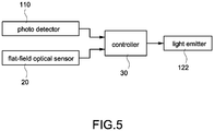
- the photo detector 110 and the flat-field optical sensor 20 are electrically connected to the controller 40.
- the controller 40 is further electrically connected to the light emitter 122.
- the controller 40 may control the optical power of the spot beam emitted from the light emitter 122 based on the optical power of the linear beam sensed by the flat-field optical sensor 20.
- the controller 40 may also control the optical power of the spot beam emitted from the light emitter 122 based on a difference between the optical power of the linear beam sensed by the flat-field optical sensor 20 and that detected by the photo detector 110.
- the controller 30 may have a lookup table providing related data for setting the optical power of the spot beam emitted from the light emitter 122 based on the optical power(s) of the linear beam sensed by the flat-field optical sensor 20 or/and detected by the photo detector 110; thus the controller 30 can obtain the optical power of the spot beam emitted from the light emitter 122 according to the lookup table while the optical power of the linear beam is sensed by the flat-field optical sensor 20 or/and detected by the photo detector 110.
- the flat-field convergent lens 140 changes its transmittance and refractive properties with age.
- the controller 30 can determine whether the flat-field convergent lens 140 ages or not based on the optical power sensed by the flat-field optical sensor 20 and that detected by the photo detector 110 since the flat-field optical sensor 20 is configured to sense the optical power of the linear beam passing through the flat-field convergent lens 140 and the photo detector 110 is configured to detect the optical power of the linear beam that does not pass through the flat-field laser convergent lens 140.
- the controller 40 may determine whether the flat-field convergent lens 140 ages or not based on the difference between the sensed signal and the detected signal. If the flat-field convergent lens 140 ages, the controller 30 may calibrate the optical power of the spot beam emitted from the light emitter 122 to make the optical power of the linear beam that has passed through the aged flat-field convergent lens 140 to be constant for stabilizing the quality of the 3D object.
- the controller 30 may generate a warning signal when the optical power of the linear beam that has passed through the flat-field laser convergent lens 20 is lower than a preset optical power to indicate to the user that the flat-field convergent lens 140 is inadequate to transmit a linear beam.
- the calibrating procedure for calibrating the optical power of the linear beam of the 3D object generating apparatus may be performed before a 3D object generating procedure is performed; however, the calibrating procedure may also be performed while the 3D object generating procedure is performed or after the 3D object generating procedure has been performed.
- the calibrating procedure for calibrating optical power of the 3D object generating apparatus starts with driving the laser light generator 120 to generate the linear beam by a controller 30, the linear beam is projected to the working region 102.
- the flat-field optical sensor 20 then senses the optical power of the linear beam and sends the sensed signal based on the sensed optical power to the controller 30.
- the controller 30 obtains the optical power of the spot beam emitted from the light emitter 122 based on the lookup table and the sensed signal.
- the controller 30 increases the optical power of the spot beam emitted from the light emitter 122.
- the controller 30 decreases the optical power of the spot beam emitted from the light emitter 122. Therefore, the optical power of the linear beam that has passed through the flat-field convergent lens 120 can be calibrated to be constant, and the quality for generating the 3D object is stabilized.
- the controller 30 may output a warning signal when the photo power of the spot beam emitted from the light emitted 122 is lower than the normal operating photo power to indicate to the user that the fluid medium 5 cannot be well cured.
- controller 30 may calibrate the optical power of the spot beam emitted from the light emitter 122 based on the sensed signal generated by the flat-field optical sensor 20 and the detected signal generated by the photo detector 110.
- the present invention provides a method for calibrating the optical power of a 3D object generating apparatus that includes the optical-transparent component 100, the flat-field convergent lens 120, and laser light generator including a light emitter 112.
- the method starts with providing the flat-field optical sensor 20 and the controller 30; the flat-field optical sensor 20 is positioned on the optical-transparent component 100, and the controller 30 is electrically connected to the flat-field optical sensor 20 and the light emitter 122.
- the flat-field optical sensor 20 senses the optical power of the linear beam generated by the laser light generator 120 and passed through the flat-field convergent lens 140 and generates a sensed signal.
- the controller 30 calibrates the optical power of the spot beam emitted by the light emitter 122 based on the sensed signal when the optical power of the linear beam passed through the flat-field convergent lens 140 is different from the preset optical power to make the optical power of the linear beam passed through the flat-field convergent lens 140 for curing the fluid medium 5 to be constant.
Landscapes
- Engineering & Computer Science (AREA)
- Chemical & Material Sciences (AREA)
- Materials Engineering (AREA)
- Physics & Mathematics (AREA)
- Optics & Photonics (AREA)
- Manufacturing & Machinery (AREA)
- Plasma & Fusion (AREA)
- Mechanical Engineering (AREA)
- Health & Medical Sciences (AREA)
- Toxicology (AREA)
- Exposure And Positioning Against Photoresist Photosensitive Materials (AREA)
- Length Measuring Devices By Optical Means (AREA)
Claims (7)
- Verfahren zum Kalibrieren einer optischen Leistung, zur Ausführung durch eine Vorrichtung zum Erzeugen eines dreidimensionalen (3D) Objekts, die einen Laserlicht-Erzeuger (120) zum Erzeugen eines linearen Strahls und eine Flachfeld-Konvergenzlinse (140) umfasst, und wobei eine Flachfeld-Abtaststrecke gebildet wird, wenn der lineare Strahl die Flachfeld-Konvergenzlinse (140) durchläuft, wobei das Verfahren umfasst:Prüfen eines optischen Flachfeldsensors (20), eines Fotodetektors (110) und einer Steuerung (30), wobei der optische Flachfeldsensor (20) auf der Flachfeld-Abtaststrecke positioniert ist, der Fotodetektor (110) zwischen dem Laserlicht-Erzeuger (120) und der Flachfeld-Konvergenzlinse (140) positioniert ist, und die Steuerung (30) elektrisch mit dem optischen Flachfeldsensor (20), dem Fotodetektor (110) und dem Laserlicht-Erzeuger (120) verbunden ist;Verwenden des optischen Flachfeldsensors (20), um eine optische Leistung des linearen Strahls, der die konvergente Flachfeldlinse (140) durchlaufen hat, abzutasten und ein erfasstes Signal, das auf der abgetasteten optischen Leistung basiert, an die Steuerung (30) zu senden;Verwenden des Fotodetektors (110), um eine optische Leistung des linearen Strahls, der die Flachfeld-Konvergenzlinse (140) nicht durchlaufen hat, zu erfassen und ein erfasstes Signal basierend auf der erfassten optischen Leistung an die Steuerung (30) zu senden; undVerwenden der Steuerung (30) zum Kalibrieren einer optischen Leistung des Laserlicht-Erzeugers (120) auf der Grundlage des erfassten Signals von dem optischen Flachfeldsensor (20) und dem erfassten Signal von dem Fotodetektor (110).
- Verfahren nach Anspruch 1, weiter umfassend:
Verwenden der Steuerung (30), um die optische Leistung des linearen Strahls zu erhöhen, der durch den Laserlicht-Erzeuger (120) erzeugt wird, wenn die optische Leistung auf der Grundlage des erfassten Signals höher als eine normale optische Betriebsleistung und niedriger als eine voreingestellte optische Leistung ist. - Verfahren nach Anspruch 2, wobei die Steuerung (30) ein Warnsignal erfasst, wenn die optische Leistung auf der Grundlage des erfassten Signals kleiner als die normale optische Betriebsleistung ist.
- Verfahren nach einem der vorhergehenden Ansprüche, wobei die Steuerung (30) die optische Leistung des linearen Strahls konstant macht.
- Vorrichtung zum Erzeugen eines dreidimensionalen (3D) Objekts, umfassend:eine optisch-durchlässige Komponente (100) mit einem Arbeitsbereich (102);ein Laserlicht-Erzeugungsmodul (160), umfassend:einen Lichtemitter (122) zum Ausgeben eines LichtLichtpunktstrahls;einen Polygonspiegel (1244), der um eine Achse drehbar ist, um den Lichtpunktstrahl in einen linearen Strahl abzulenken;eine Flachfeld-Konvergenzlinse (140), die zwischen dem Laserlicht-Erzeugungsmodul (160) und der optisch transparenten Komponente (100) angeordnet ist, wobei eine Flachfeld-Abtaststrecke gebildet wird, nachdem der lineare Strahl die Flachfeld-Konvergenzlinse (140) durchlaufen hat, und wobei der Arbeitsbereich (102) innerhalb eines abgedeckten Bereichs der Flachfeld-Abtaststrecke liegt,dadurch gekennzeichnet, dassein optischer Flachfeldsensor (20) zwischen der Flachfeld-Konvergenzlinse (140) und der optisch transparenten Komponente (100) angeordnet und auf der Flachfeld-Abtaststrecke angeordnet ist, wobei der optische Flachfeldsensor (20) so konfiguriert ist, dass er eine optische Leistung des linearen Strahls, der die Flachfeld-Konvergenzlinse (140) durchlaufen hat, erfasst und ein erfasstes Signal basierend auf der optischen Leistung des linearen Strahls, der die Flachfeld-Konvergenzlinse (140) durchlaufen hat, erzeugt;einen Fotodetektor (110), der zwischen dem Laserlicht-Erzeugungsmodul (160) und der Flachfeld-Konvergenzlinse (140) angeordnet ist, wobei der Fotodetektor (110) so konfiguriert ist, dass er eine optische Leistung des linearen Strahls, der die Flachfeld-Konvergenzlinse (140) nicht durchlaufen hat, erfasst und ein erfasstes Signal erzeugt; undeine Steuerung (30), die elektrisch mit dem Laserlicht-Erzeugungsmodul (160), dem optischen Flachfeldsensor (20) und dem Fotodetektor (110) verbunden ist,wobei die Steuerung (30) das erfasste Signal von dem optischen Flachfeldsensor (20) und das erfasste Signal von dem Fotodetektor (110) empfängt und die optische Leistung des Lichtpunktstrahls auf der Grundlage des erfassten Signals von dem optischen Flachfeldsensor (20) und des erfassten Signals von dem Fotodetektor (110) kalibriert.
- Vorrichtung nach Anspruch 5, weiter umfassend:einen Reflektor (150), der zwischen dem Laserlicht-Erzeugungsmodul (160) und dem Fotodetektor (110) angeordnet ist, um einen Teil des linearen Strahls von dem Polygonspiegel (1244) zu dem Fotodetektor (110) umzulenken; undeine konvergierende Komponente (112), die zwischen dem Reflektor (150) und dem Fotodetektor (110) so positioniert ist, dass ein Brennpunkt der konvergierenden Komponente (112) auf dem Fotodetektor (110) liegt.
- Vorrichtung nach Anspruch 5 oder 6, wobei der optische Flachfeldsensor (20) aus einem ladungsgekoppelten Bauelement oder einem komplementären Metalloxid-Halbleiter besteht.
Applications Claiming Priority (1)
| Application Number | Priority Date | Filing Date | Title |
|---|---|---|---|
| CN201610072685.XA CN107031035B (zh) | 2016-02-02 | 2016-02-02 | 立体物件成型系统及其校正方法 |
Publications (2)
| Publication Number | Publication Date |
|---|---|
| EP3202525A1 EP3202525A1 (de) | 2017-08-09 |
| EP3202525B1 true EP3202525B1 (de) | 2020-08-12 |
Family
ID=55952981
Family Applications (1)
| Application Number | Title | Priority Date | Filing Date |
|---|---|---|---|
| EP16167723.2A Not-in-force EP3202525B1 (de) | 2016-02-02 | 2016-04-29 | Vorrichtung zur erzeugung eines dreidimensionalen objekts und verfahren zur kalibrierung davon |
Country Status (5)
| Country | Link |
|---|---|
| US (1) | US10207488B2 (de) |
| EP (1) | EP3202525B1 (de) |
| JP (1) | JP6509261B2 (de) |
| CN (1) | CN107031035B (de) |
| ES (1) | ES2823849T3 (de) |
Families Citing this family (7)
| Publication number | Priority date | Publication date | Assignee | Title |
|---|---|---|---|---|
| US10717230B2 (en) * | 2016-06-16 | 2020-07-21 | Xerox Corporation | Line laser imager for thermoplastic selective laser sintering |
| CN109664502A (zh) * | 2017-10-16 | 2019-04-23 | 三纬国际立体列印科技股份有限公司 | 立体打印装置 |
| NL2019998B1 (en) * | 2017-11-30 | 2019-06-07 | Additive Ind Bv | Apparatus for producing an object by means of additive manufacturing |
| KR20190088116A (ko) * | 2018-01-04 | 2019-07-26 | 주식회사신도리코 | 냉각 기능을 구비한 3차원 프린터 |
| ES2916577T3 (es) * | 2019-02-27 | 2022-07-01 | Ivoclar Vivadent Ag | Dispositivo de estereolitografía y un procedimiento para ajustar un dispositivo de estereolitografía |
| EP3938177B1 (de) | 2019-03-15 | 2024-05-01 | Formlabs, Inc. | Verfahren und system zur kalibrierung von optischen modulen für additive herstellungsvorrichtungen |
| CN112339265A (zh) * | 2019-08-08 | 2021-02-09 | 安世亚太科技股份有限公司 | 一种用于光敏树脂的3d打印机系统及利用其的3d打印方法 |
Family Cites Families (10)
| Publication number | Priority date | Publication date | Assignee | Title |
|---|---|---|---|---|
| JPH04368190A (ja) * | 1991-06-17 | 1992-12-21 | Mitsui Eng & Shipbuild Co Ltd | レーザ発振器の出力調節方法 |
| US6129884A (en) * | 1999-02-08 | 2000-10-10 | 3D Systems, Inc. | Stereolithographic method and apparatus with enhanced control of prescribed stimulation production and application |
| US6241934B1 (en) * | 1999-02-08 | 2001-06-05 | 3D Systems, Inc. | Stereolithographic method and apparatus with enhanced control of prescribed stimulation production and application |
| JP2000238137A (ja) * | 1999-02-17 | 2000-09-05 | Mitsubishi Heavy Ind Ltd | 光造形装置及び光造形方法 |
| US6940037B1 (en) * | 2003-08-25 | 2005-09-06 | Southern Methodist University | System and method for controlling welding parameters in welding-based deposition processes |
| JP2009113294A (ja) * | 2007-11-05 | 2009-05-28 | Sony Corp | 光造形装置及び光造形方法 |
| DE102007062129B3 (de) * | 2007-12-21 | 2009-06-18 | Eos Gmbh Electro Optical Systems | Verfahren zum Herstellen eines dreidimensionalen Objekts |
| WO2012074986A1 (en) * | 2010-11-29 | 2012-06-07 | 3D Systems, Inc. | Stereolithography systems and methods using internal laser modulation |
| ES2681980T3 (es) * | 2011-06-28 | 2018-09-17 | Global Filtration Systems, A Dba Of Gulf Filtration Systems Inc. | Aparato para formar objetos tridimensionales utilizando solidificación lineal |
| US9586364B2 (en) * | 2013-11-27 | 2017-03-07 | Global Filtration Systems | Apparatus and method for forming three-dimensional objects using linear solidification with contourless object data |
-
2016
- 2016-02-02 CN CN201610072685.XA patent/CN107031035B/zh not_active Expired - Fee Related
- 2016-03-22 US US15/077,612 patent/US10207488B2/en not_active Expired - Fee Related
- 2016-04-29 ES ES16167723T patent/ES2823849T3/es active Active
- 2016-04-29 EP EP16167723.2A patent/EP3202525B1/de not_active Not-in-force
-
2017
- 2017-01-26 JP JP2017011826A patent/JP6509261B2/ja not_active Expired - Fee Related
Non-Patent Citations (1)
| Title |
|---|
| None * |
Also Published As
| Publication number | Publication date |
|---|---|
| EP3202525A1 (de) | 2017-08-09 |
| ES2823849T3 (es) | 2021-05-10 |
| US20170217099A1 (en) | 2017-08-03 |
| CN107031035A (zh) | 2017-08-11 |
| JP6509261B2 (ja) | 2019-05-08 |
| JP2017136843A (ja) | 2017-08-10 |
| US10207488B2 (en) | 2019-02-19 |
| CN107031035B (zh) | 2019-07-12 |
Similar Documents
| Publication | Publication Date | Title |
|---|---|---|
| US10207488B2 (en) | Three-dimensional object generating apparatus | |
| US12162222B2 (en) | Method for calibrating a device for producing a three-dimensional object and device configured for implementing said method | |
| EP3162542B1 (de) | Verfahren zur kalibrierung eines lichts einer vorrichtung zur erzeugung eines dreidimensionalen objekts | |
| JP6771076B2 (ja) | 三次元の部材の生成的な製造の為の装置 | |
| US6600129B2 (en) | Device and process for sintering a powder with a laser beam | |
| CN102985214B (zh) | 用于使激光射束聚焦的射束成型单元及其控制方法 | |
| US8648279B2 (en) | Process control apparatus and laser processing apparatus | |
| JP2020505625A5 (de) | ||
| KR101850222B1 (ko) | 삼차원 프린터의 축 오차 보정 장치 및 방법 | |
| KR101728876B1 (ko) | 자동 초점 조절 구조의 레이저 마킹 장치 및 그에 의한 레이저 마킹 방법 | |
| US20180272614A1 (en) | Optical device production apparatus and optical device production method | |
| KR102018570B1 (ko) | 3d 프린터의 자동정렬시스템 | |
| CN110757789A (zh) | 光固化3d打印机及其光源补偿打印方法 | |
| CN111465484B (zh) | 用于通过增材制造来生产物体的设备和方法 | |
| JP7084508B2 (ja) | レーザ較正システムを備えた三次元プリントシステム | |
| KR101918979B1 (ko) | 디엘피 프로젝터 및 레이저 스캐너를 병용하는 3차원 프린팅 장치 | |
| US20260115834A1 (en) | Apparatus and method for additively manufacturing three-dimensional objects | |
| US20190240907A1 (en) | Apparatus for additively manufacturing three-dimensional objects | |
| JP2021530369A (ja) | 外部振動に応答する三次元プリンタ | |
| JP2020028891A (ja) | 光学装置及び加工装置 | |
| KR101704547B1 (ko) | 단방향으로 회전하는 폴리곤미러를 구비하고 조형광선의 빔스팟크기 조절기능을 갖는 입체조형장비의 헤드장치 및 이를 이용하는 조형평면의 스캐닝방법 및 이를 이용하는 입체조형장치. |
Legal Events
| Date | Code | Title | Description |
|---|---|---|---|
| PUAI | Public reference made under article 153(3) epc to a published international application that has entered the european phase |
Free format text: ORIGINAL CODE: 0009012 |
|
| STAA | Information on the status of an ep patent application or granted ep patent |
Free format text: STATUS: THE APPLICATION HAS BEEN PUBLISHED |
|
| AK | Designated contracting states |
Kind code of ref document: A1 Designated state(s): AL AT BE BG CH CY CZ DE DK EE ES FI FR GB GR HR HU IE IS IT LI LT LU LV MC MK MT NL NO PL PT RO RS SE SI SK SM TR |
|
| AX | Request for extension of the european patent |
Extension state: BA ME |
|
| STAA | Information on the status of an ep patent application or granted ep patent |
Free format text: STATUS: REQUEST FOR EXAMINATION WAS MADE |
|
| 17P | Request for examination filed |
Effective date: 20180206 |
|
| RBV | Designated contracting states (corrected) |
Designated state(s): AL AT BE BG CH CY CZ DE DK EE ES FI FR GB GR HR HU IE IS IT LI LT LU LV MC MK MT NL NO PL PT RO RS SE SI SK SM TR |
|
| GRAP | Despatch of communication of intention to grant a patent |
Free format text: ORIGINAL CODE: EPIDOSNIGR1 |
|
| STAA | Information on the status of an ep patent application or granted ep patent |
Free format text: STATUS: GRANT OF PATENT IS INTENDED |
|
| RIC1 | Information provided on ipc code assigned before grant |
Ipc: B29C 67/00 20170101ALI20200225BHEP Ipc: B23K 26/342 20140101AFI20200225BHEP |
|
| INTG | Intention to grant announced |
Effective date: 20200325 |
|
| GRAS | Grant fee paid |
Free format text: ORIGINAL CODE: EPIDOSNIGR3 |
|
| GRAA | (expected) grant |
Free format text: ORIGINAL CODE: 0009210 |
|
| STAA | Information on the status of an ep patent application or granted ep patent |
Free format text: STATUS: THE PATENT HAS BEEN GRANTED |
|
| AK | Designated contracting states |
Kind code of ref document: B1 Designated state(s): AL AT BE BG CH CY CZ DE DK EE ES FI FR GB GR HR HU IE IS IT LI LT LU LV MC MK MT NL NO PL PT RO RS SE SI SK SM TR |
|
| REG | Reference to a national code |
Ref country code: CH Ref legal event code: EP |
|
| REG | Reference to a national code |
Ref country code: IE Ref legal event code: FG4D |
|
| REG | Reference to a national code |
Ref country code: DE Ref legal event code: R096 Ref document number: 602016041731 Country of ref document: DE |
|
| REG | Reference to a national code |
Ref country code: AT Ref legal event code: REF Ref document number: 1301079 Country of ref document: AT Kind code of ref document: T Effective date: 20200915 |
|
| REG | Reference to a national code |
Ref country code: LT Ref legal event code: MG4D |
|
| REG | Reference to a national code |
Ref country code: NL Ref legal event code: MP Effective date: 20200812 |
|
| PG25 | Lapsed in a contracting state [announced via postgrant information from national office to epo] |
Ref country code: LT Free format text: LAPSE BECAUSE OF FAILURE TO SUBMIT A TRANSLATION OF THE DESCRIPTION OR TO PAY THE FEE WITHIN THE PRESCRIBED TIME-LIMIT Effective date: 20200812 Ref country code: BG Free format text: LAPSE BECAUSE OF FAILURE TO SUBMIT A TRANSLATION OF THE DESCRIPTION OR TO PAY THE FEE WITHIN THE PRESCRIBED TIME-LIMIT Effective date: 20201112 Ref country code: SE Free format text: LAPSE BECAUSE OF FAILURE TO SUBMIT A TRANSLATION OF THE DESCRIPTION OR TO PAY THE FEE WITHIN THE PRESCRIBED TIME-LIMIT Effective date: 20200812 Ref country code: NO Free format text: LAPSE BECAUSE OF FAILURE TO SUBMIT A TRANSLATION OF THE DESCRIPTION OR TO PAY THE FEE WITHIN THE PRESCRIBED TIME-LIMIT Effective date: 20201112 Ref country code: HR Free format text: LAPSE BECAUSE OF FAILURE TO SUBMIT A TRANSLATION OF THE DESCRIPTION OR TO PAY THE FEE WITHIN THE PRESCRIBED TIME-LIMIT Effective date: 20200812 Ref country code: GR Free format text: LAPSE BECAUSE OF FAILURE TO SUBMIT A TRANSLATION OF THE DESCRIPTION OR TO PAY THE FEE WITHIN THE PRESCRIBED TIME-LIMIT Effective date: 20201113 Ref country code: FI Free format text: LAPSE BECAUSE OF FAILURE TO SUBMIT A TRANSLATION OF THE DESCRIPTION OR TO PAY THE FEE WITHIN THE PRESCRIBED TIME-LIMIT Effective date: 20200812 |
|
| REG | Reference to a national code |
Ref country code: AT Ref legal event code: MK05 Ref document number: 1301079 Country of ref document: AT Kind code of ref document: T Effective date: 20200812 |
|
| PG25 | Lapsed in a contracting state [announced via postgrant information from national office to epo] |
Ref country code: RS Free format text: LAPSE BECAUSE OF FAILURE TO SUBMIT A TRANSLATION OF THE DESCRIPTION OR TO PAY THE FEE WITHIN THE PRESCRIBED TIME-LIMIT Effective date: 20200812 Ref country code: NL Free format text: LAPSE BECAUSE OF FAILURE TO SUBMIT A TRANSLATION OF THE DESCRIPTION OR TO PAY THE FEE WITHIN THE PRESCRIBED TIME-LIMIT Effective date: 20200812 Ref country code: LV Free format text: LAPSE BECAUSE OF FAILURE TO SUBMIT A TRANSLATION OF THE DESCRIPTION OR TO PAY THE FEE WITHIN THE PRESCRIBED TIME-LIMIT Effective date: 20200812 Ref country code: PL Free format text: LAPSE BECAUSE OF FAILURE TO SUBMIT A TRANSLATION OF THE DESCRIPTION OR TO PAY THE FEE WITHIN THE PRESCRIBED TIME-LIMIT Effective date: 20200812 Ref country code: IS Free format text: LAPSE BECAUSE OF FAILURE TO SUBMIT A TRANSLATION OF THE DESCRIPTION OR TO PAY THE FEE WITHIN THE PRESCRIBED TIME-LIMIT Effective date: 20201212 |
|
| PG25 | Lapsed in a contracting state [announced via postgrant information from national office to epo] |
Ref country code: EE Free format text: LAPSE BECAUSE OF FAILURE TO SUBMIT A TRANSLATION OF THE DESCRIPTION OR TO PAY THE FEE WITHIN THE PRESCRIBED TIME-LIMIT Effective date: 20200812 Ref country code: RO Free format text: LAPSE BECAUSE OF FAILURE TO SUBMIT A TRANSLATION OF THE DESCRIPTION OR TO PAY THE FEE WITHIN THE PRESCRIBED TIME-LIMIT Effective date: 20200812 Ref country code: SM Free format text: LAPSE BECAUSE OF FAILURE TO SUBMIT A TRANSLATION OF THE DESCRIPTION OR TO PAY THE FEE WITHIN THE PRESCRIBED TIME-LIMIT Effective date: 20200812 Ref country code: DK Free format text: LAPSE BECAUSE OF FAILURE TO SUBMIT A TRANSLATION OF THE DESCRIPTION OR TO PAY THE FEE WITHIN THE PRESCRIBED TIME-LIMIT Effective date: 20200812 Ref country code: CZ Free format text: LAPSE BECAUSE OF FAILURE TO SUBMIT A TRANSLATION OF THE DESCRIPTION OR TO PAY THE FEE WITHIN THE PRESCRIBED TIME-LIMIT Effective date: 20200812 |
|
| REG | Reference to a national code |
Ref country code: ES Ref legal event code: FG2A Ref document number: 2823849 Country of ref document: ES Kind code of ref document: T3 Effective date: 20210510 |
|
| REG | Reference to a national code |
Ref country code: DE Ref legal event code: R097 Ref document number: 602016041731 Country of ref document: DE |
|
| PG25 | Lapsed in a contracting state [announced via postgrant information from national office to epo] |
Ref country code: AL Free format text: LAPSE BECAUSE OF FAILURE TO SUBMIT A TRANSLATION OF THE DESCRIPTION OR TO PAY THE FEE WITHIN THE PRESCRIBED TIME-LIMIT Effective date: 20200812 Ref country code: AT Free format text: LAPSE BECAUSE OF FAILURE TO SUBMIT A TRANSLATION OF THE DESCRIPTION OR TO PAY THE FEE WITHIN THE PRESCRIBED TIME-LIMIT Effective date: 20200812 |
|
| PLBE | No opposition filed within time limit |
Free format text: ORIGINAL CODE: 0009261 |
|
| STAA | Information on the status of an ep patent application or granted ep patent |
Free format text: STATUS: NO OPPOSITION FILED WITHIN TIME LIMIT |
|
| PG25 | Lapsed in a contracting state [announced via postgrant information from national office to epo] |
Ref country code: SK Free format text: LAPSE BECAUSE OF FAILURE TO SUBMIT A TRANSLATION OF THE DESCRIPTION OR TO PAY THE FEE WITHIN THE PRESCRIBED TIME-LIMIT Effective date: 20200812 |
|
| 26N | No opposition filed |
Effective date: 20210514 |
|
| PG25 | Lapsed in a contracting state [announced via postgrant information from national office to epo] |
Ref country code: SI Free format text: LAPSE BECAUSE OF FAILURE TO SUBMIT A TRANSLATION OF THE DESCRIPTION OR TO PAY THE FEE WITHIN THE PRESCRIBED TIME-LIMIT Effective date: 20200812 |
|
| REG | Reference to a national code |
Ref country code: DE Ref legal event code: R119 Ref document number: 602016041731 Country of ref document: DE |
|
| PG25 | Lapsed in a contracting state [announced via postgrant information from national office to epo] |
Ref country code: MC Free format text: LAPSE BECAUSE OF FAILURE TO SUBMIT A TRANSLATION OF THE DESCRIPTION OR TO PAY THE FEE WITHIN THE PRESCRIBED TIME-LIMIT Effective date: 20200812 |
|
| GBPC | Gb: european patent ceased through non-payment of renewal fee |
Effective date: 20210429 |
|
| PG25 | Lapsed in a contracting state [announced via postgrant information from national office to epo] |
Ref country code: LU Free format text: LAPSE BECAUSE OF NON-PAYMENT OF DUE FEES Effective date: 20210429 |
|
| REG | Reference to a national code |
Ref country code: BE Ref legal event code: MM Effective date: 20210430 |
|
| PG25 | Lapsed in a contracting state [announced via postgrant information from national office to epo] |
Ref country code: CH Free format text: LAPSE BECAUSE OF NON-PAYMENT OF DUE FEES Effective date: 20210430 Ref country code: LI Free format text: LAPSE BECAUSE OF NON-PAYMENT OF DUE FEES Effective date: 20210430 Ref country code: DE Free format text: LAPSE BECAUSE OF NON-PAYMENT OF DUE FEES Effective date: 20211103 Ref country code: GB Free format text: LAPSE BECAUSE OF NON-PAYMENT OF DUE FEES Effective date: 20210429 Ref country code: FR Free format text: LAPSE BECAUSE OF NON-PAYMENT OF DUE FEES Effective date: 20210430 |
|
| PG25 | Lapsed in a contracting state [announced via postgrant information from national office to epo] |
Ref country code: IE Free format text: LAPSE BECAUSE OF NON-PAYMENT OF DUE FEES Effective date: 20210429 |
|
| PG25 | Lapsed in a contracting state [announced via postgrant information from national office to epo] |
Ref country code: IS Free format text: LAPSE BECAUSE OF FAILURE TO SUBMIT A TRANSLATION OF THE DESCRIPTION OR TO PAY THE FEE WITHIN THE PRESCRIBED TIME-LIMIT Effective date: 20201212 |
|
| REG | Reference to a national code |
Ref country code: ES Ref legal event code: FD2A Effective date: 20220706 |
|
| PG25 | Lapsed in a contracting state [announced via postgrant information from national office to epo] |
Ref country code: ES Free format text: LAPSE BECAUSE OF NON-PAYMENT OF DUE FEES Effective date: 20210430 Ref country code: BE Free format text: LAPSE BECAUSE OF NON-PAYMENT OF DUE FEES Effective date: 20210430 |
|
| PG25 | Lapsed in a contracting state [announced via postgrant information from national office to epo] |
Ref country code: IT Free format text: LAPSE BECAUSE OF NON-PAYMENT OF DUE FEES Effective date: 20210429 |
|
| PG25 | Lapsed in a contracting state [announced via postgrant information from national office to epo] |
Ref country code: PT Free format text: LAPSE BECAUSE OF FAILURE TO SUBMIT A TRANSLATION OF THE DESCRIPTION OR TO PAY THE FEE WITHIN THE PRESCRIBED TIME-LIMIT Effective date: 20201214 |
|
| PG25 | Lapsed in a contracting state [announced via postgrant information from national office to epo] |
Ref country code: HU Free format text: LAPSE BECAUSE OF FAILURE TO SUBMIT A TRANSLATION OF THE DESCRIPTION OR TO PAY THE FEE WITHIN THE PRESCRIBED TIME-LIMIT; INVALID AB INITIO Effective date: 20160429 |
|
| PG25 | Lapsed in a contracting state [announced via postgrant information from national office to epo] |
Ref country code: CY Free format text: LAPSE BECAUSE OF FAILURE TO SUBMIT A TRANSLATION OF THE DESCRIPTION OR TO PAY THE FEE WITHIN THE PRESCRIBED TIME-LIMIT Effective date: 20200812 |
|
| PG25 | Lapsed in a contracting state [announced via postgrant information from national office to epo] |
Ref country code: MK Free format text: LAPSE BECAUSE OF FAILURE TO SUBMIT A TRANSLATION OF THE DESCRIPTION OR TO PAY THE FEE WITHIN THE PRESCRIBED TIME-LIMIT Effective date: 20200812 |
|
| PG25 | Lapsed in a contracting state [announced via postgrant information from national office to epo] |
Ref country code: TR Free format text: LAPSE BECAUSE OF FAILURE TO SUBMIT A TRANSLATION OF THE DESCRIPTION OR TO PAY THE FEE WITHIN THE PRESCRIBED TIME-LIMIT Effective date: 20200812 |
|
| PG25 | Lapsed in a contracting state [announced via postgrant information from national office to epo] |
Ref country code: MT Free format text: LAPSE BECAUSE OF FAILURE TO SUBMIT A TRANSLATION OF THE DESCRIPTION OR TO PAY THE FEE WITHIN THE PRESCRIBED TIME-LIMIT Effective date: 20200812 |