EP3201650B1 - Fensterkappe für das gehäuse einer abtastenden optoelektronischen messvorrichtung und gehäuse mit einer solchen - Google Patents
Fensterkappe für das gehäuse einer abtastenden optoelektronischen messvorrichtung und gehäuse mit einer solchen Download PDFInfo
- Publication number
- EP3201650B1 EP3201650B1 EP15763856.0A EP15763856A EP3201650B1 EP 3201650 B1 EP3201650 B1 EP 3201650B1 EP 15763856 A EP15763856 A EP 15763856A EP 3201650 B1 EP3201650 B1 EP 3201650B1
- Authority
- EP
- European Patent Office
- Prior art keywords
- window
- housing
- edge
- cap
- wall
- Prior art date
- Legal status (The legal status is an assumption and is not a legal conclusion. Google has not performed a legal analysis and makes no representation as to the accuracy of the status listed.)
- Active
Links
Images
Classifications
-
- G—PHYSICS
- G01—MEASURING; TESTING
- G01S—RADIO DIRECTION-FINDING; RADIO NAVIGATION; DETERMINING DISTANCE OR VELOCITY BY USE OF RADIO WAVES; LOCATING OR PRESENCE-DETECTING BY USE OF THE REFLECTION OR RERADIATION OF RADIO WAVES; ANALOGOUS ARRANGEMENTS USING OTHER WAVES
- G01S7/00—Details of systems according to groups G01S13/00, G01S15/00, G01S17/00
- G01S7/48—Details of systems according to groups G01S13/00, G01S15/00, G01S17/00 of systems according to group G01S17/00
- G01S7/481—Constructional features, e.g. arrangements of optical elements
- G01S7/4811—Constructional features, e.g. arrangements of optical elements common to transmitter and receiver
- G01S7/4813—Housing arrangements
-
- G—PHYSICS
- G01—MEASURING; TESTING
- G01S—RADIO DIRECTION-FINDING; RADIO NAVIGATION; DETERMINING DISTANCE OR VELOCITY BY USE OF RADIO WAVES; LOCATING OR PRESENCE-DETECTING BY USE OF THE REFLECTION OR RERADIATION OF RADIO WAVES; ANALOGOUS ARRANGEMENTS USING OTHER WAVES
- G01S17/00—Systems using the reflection or reradiation of electromagnetic waves other than radio waves, e.g. lidar systems
- G01S17/88—Lidar systems specially adapted for specific applications
- G01S17/93—Lidar systems specially adapted for specific applications for anti-collision purposes
- G01S17/931—Lidar systems specially adapted for specific applications for anti-collision purposes of land vehicles
-
- G—PHYSICS
- G01—MEASURING; TESTING
- G01S—RADIO DIRECTION-FINDING; RADIO NAVIGATION; DETERMINING DISTANCE OR VELOCITY BY USE OF RADIO WAVES; LOCATING OR PRESENCE-DETECTING BY USE OF THE REFLECTION OR RERADIATION OF RADIO WAVES; ANALOGOUS ARRANGEMENTS USING OTHER WAVES
- G01S7/00—Details of systems according to groups G01S13/00, G01S15/00, G01S17/00
- G01S7/48—Details of systems according to groups G01S13/00, G01S15/00, G01S17/00 of systems according to group G01S17/00
- G01S7/497—Means for monitoring or calibrating
- G01S2007/4975—Means for monitoring or calibrating of sensor obstruction by, e.g. dirt- or ice-coating, e.g. by reflection measurement on front-screen
- G01S2007/4977—Means for monitoring or calibrating of sensor obstruction by, e.g. dirt- or ice-coating, e.g. by reflection measurement on front-screen including means to prevent or remove the obstruction
Definitions
- the invention relates to a housing for a scanning optoelectronic measuring device, in particular a laser scanner for a motor vehicle, with a window cap with a window that is transparent to electromagnetic measuring beams of the measuring device and an edge wall that is configured at an angle to the window and forms a circumferential contour, the window cap having a window heater with heating loops for Has heating of the transparent window, is pushed onto a peripheral window edge of the housing outside and is fixed in a window edge overlapping portion of the edge wall.
- Laser-based systems also known as “LIDAR” (“Light detection and ranging”), are used for optical distance and speed measurement and enable the detection of objects in the vehicle's surroundings with a very high level of measurement accuracy.
- Known optical measuring devices include a housing in which at least one optical transmitter for emitting at least one transmitted beam and at least one optical receiver for receiving a received beam are arranged.
- Such an optical measuring device is out DE 10 2011 122 345 A1 famous.
- the receiver receives the rays reflected from objects and/or obstacles and determines the distance to the objects and/or obstacles according to the time-of-flight principle.
- the housing is closed off by a cover disk, which forms a window that is transparent to electromagnetic measuring beams of the measuring device.
- a transmission window and a reception window are provided, with transmission beams emerging from the housing through the transmission window. Transmission beams reflected from the surroundings can penetrate the housing through the reception window. If reflected transmission beams fall on the receiver arranged in the housing, a corresponding reception signal is provided.
- a collision avoidance system which includes an object detection module mounted on a vehicle to detect objects in a zone adjacent to the vehicle.
- a radar device which transmits a transmission wave to a periphery of a vehicle through a window part and detects a reflected wave of the transmission wave.
- a laser radar is known to measure distances between vehicles in a collision alarm system.
- the optical measuring devices are usually installed behind a radiator grille of a motor vehicle and are therefore exposed to the effects of the weather such as snow, ice and/or water.
- the cover plate is heated indirectly via at least one electric heating element.
- the heating device is arranged essentially in the region of the reception window, which prevents the transmission beams from being distorted by the heating device during transmission.
- known laser scanners tend to form an ice/snow collar, with a tongue of ice/snow often pushing over the cover pane and influencing the detection range of the laser scanner or completely eliminating it.
- the present invention is based on the object of the operability of an optoelectronic measuring device, in particular a laser scanner for a Motor vehicle to improve under cold weather conditions.
- the window that is transparent to electromagnetic measuring beams of the measuring device is designed as a component of a window cap, which comprises an edge wall that is designed at an angle to the window and forms a peripheral contour.
- the window and the edge wall are at an angle to one another, as a result of which the edge wall and the window delimit a volume.
- a window that is transparent to electromagnetic measuring beams of the measuring device means that the window or the material that forms the transparent window is transparent in the spectral range of the electromagnetic rays, preferably in the infrared range. In other spectral ranges, the window is not transparent and serves in particular as a blocking filter for daylight.
- the edge wall is a peripheral wall which is connected to the window on the one hand and forms a free edge on the other.
- the window is the bottom of a window cap, which is thus cup-shaped.
- the window cap is pushed onto a peripheral window edge of the housing and is fastened in a section of the edge wall of the window cap that overlaps the window edge.
- the window cap according to the invention moves the interface from the front area to a section which is significantly less exposed to environmental influences.
- the window cap is fastened on the inside in the section overlapping the window edge of the housing, which means that the connection point is significantly better protected against environmental influences caused by driving and high-pressure cleaning than with conventional measuring devices.
- the contour of the peripheral edge wall of the window cap is preferably congruent to the peripheral window edge of the housing.
- the congruent contours are designed in such a way that between an internal gap is formed between the window cap and the housing, in which a connecting means is attached.
- the window flap is glued to the window edge of the housing.
- An adhesive can be inserted with simple means into the internal adhesive gap formed between the window cap and the housing, for example an adhesive strip.
- the edge wall of the window cap has four wall sections, two of which are parallel to one another.
- the laser scanner can be installed quickly and easily.
- at least two of the wall sections carry guide tongues projecting beyond the edge of the peripheral wall.
- the guide tongues advantageously interact with guide grooves in the area of the window edge of the housing and promote precise alignment of the window cap when it is fastened to the housing.
- the window which is transparent for electromagnetic measuring beams of the measuring device, is advantageously curved outwards, so that a large detection range of the laser scanner is provided with a compact size of the housing.
- the outwardly curved shape of the transparent window also offers reduced flow resistance and promotes the drainage of water droplets.
- the window cap is a one-piece component made of a material that is transparent to electromagnetic measuring beams of the measuring device.
- a one-piece component is easy to handle and can be assembled with little effort.
- the window edge of the housing onto which the window cap is pushed according to the invention and is glued on the inside, is formed by a frame fastened to the housing.
- the frame which forms the edge of the window, can be fastened to the housing away from the areas exposed to the effects of the weather, which facilitates the assembly and in particular the disassembly of a window cap that may have been damaged during operation of the motor vehicle.
- the edge wall of the window cap is designed in such a way that the edge wall or its wall sections terminate flush with the housing in the installation position of the window cap. In this way, an attractive design is ensured with an internal attachment of the window cap with a quasi-invisible circumferential edge wall, which is increasingly important when using the housing with a window cap in measuring devices for motor vehicles.
- the window cap has a pane heater, which heats the transparent window via heating loops.
- the window heating is advantageously implemented by applying a conductive, permanently adhesive compound to the inside of the window cap.
- An even distribution of heat is given with two or more heating loops connected in parallel, which are advantageously of the same length.
- the transmission window that is to say the emitter area, is free of heating loops, which means that the transmission beams cannot be influenced by the heating loops.
- the conductor tracks of the heating loops are contacted with an electrical supply of the heating device by means of contact springs.
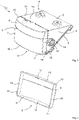
- FIG. 1 shows a perspective view of a housing 1 for a laser scanner.
- the electronics of the laser scanner are arranged in the housing 1, namely at least one optical transmitter for emitting electromagnetic radiation and a receiver for receiving reflected radiation.
- the housing 1 has a bottom wall 2 and a top wall 3 which are connected to one another by side walls 4 on both sides of the housing 1 .
- the bottom wall 2, the top wall 3 and the side walls 4 enclose an interior space in which the electronics of the Laser scanner is included.
- the housing 1 ensures electromagnetic shielding of the electronics inside it.
- the bottom wall 2, the top wall 3 and the side walls 4 form an open end face of the housing 1, which is covered by a window 5 that is transparent to electromagnetic measuring beams of the measuring device.
- the window 5 has two sub-areas, namely a transmission window 6 assigned to the optical transmitter and a reception window 7 assigned to the receiver.
- the optical transmitter and the receiver inside the laser scanner each have optics which are assigned to the respective section of the window . Accordingly, an optical system of the optical transmitter guides the transmission beams emitted by the optical transmitter through the transmission window 6 of the window 5 to the outside.
- the reflected beams falling through the reception window 7 of the window 5 into the housing and the optics of the receiver arranged behind them are redirected to the receiver by the optics (not shown).
- the window 5 is curved outwards, as a result of which the detection range of the laser scanner is increased and the air resistance is also reduced. In addition, when using the laser scanner on motor vehicles when driving in the rain, the drainage of water droplets is promoted.
- the window 5 is part of a window cap 8, which is inserted from the rear in 2 is shown.
- the same reference symbols are used in both drawing figures for the same features.
- the window cap 8 has an edge wall 10 formed at an angle to the window 5 .
- the edge wall 10 forms a peripheral contour 9 so that the window cap is a cup-shaped component with an opening defined by the edge wall 10 due to the edge wall 10 and the transparent window 5 .
- the window cap 8 with the transparent window 5 and the edge wall 10 is a one-piece component made from the material that is transparent to the electromagnetic measuring beams of the measuring device. The material is selected in such a way that there is transparency in the spectral range of the electromagnetic measuring beams and daylight is blocked at the same time.
- the window cap 8 forms thus a blocking filter for daylight.
- a circumferential window edge 11 is formed on the housing 1, onto which the window cap 8 is pushed on the outside.
- the edge of the window 11 is formed with flat sections, at least along its peripheral edge, which run essentially perpendicular to the plane delimited by the base wall 2, the cover wall 3 and the side walls 4.
- the edge of the window 11 delimits a contour which is congruent to the contour 9 of the edge wall 10 of the window cap 8 or its sections.
- the contour of the edge wall 10 of the window cap 8 and the contour of the window edge 11 are matched to one another in such a way that an internal gap is formed between the window cap 8 and the housing 1 .
- a connecting means, which holds the window cap 4 to the housing 1, is attached in the internal gap.
- the window cap 8 is glued to the window edge 11 of the housing 1.
- the mutually overlapping sections of the edge wall 10 and the window edge 11 are connected to one another circumferentially, in particular by means of an adhesive strip.
- connection of the window cap 8 to the housing 1 is on an inside 19 of the edge wall 10 of the window cap 8.
- the connecting means in particular an adhesive strip, is therefore on the inside 19 of the window cap 8 protected from the weather.
- the edge of the window 11 is formed by a frame 12 which in turn is fastened to the housing 1 .
- the side wall 4 of the window cap 1 has four side wall sections 13, 14, 15, 16, two of which are parallel to one another. In this way, the window cap 8 forms a cover which can be pushed onto the housing 1 and the housing 1 closes.
- At least two of the side wall sections 13 , 14 , 15 , 16 have guide tongues 17 protruding beyond the edge of the edge wall 10 .
- a guide groove 18 is formed in each case at the level of the guide tongues 17 of the window cap 8 .
- the guide groove 18 interacts with the guide tongues 17, the guide tongues 17 being able to be pushed into the guide grooves 18 when the window cap is pushed onto the housing 1 are. In this way, the guide tongues 17 and the guide grooves 18 form a guide which positions the window cap during the connection process or when the window cap 8 is glued to the housing 1 .
- At least the top wall 3 and the two side walls 4 are each assigned a guide, i.e. a guide tongue 17 on the corresponding side wall sections 13, 14, 15.
Landscapes
- Engineering & Computer Science (AREA)
- Physics & Mathematics (AREA)
- Computer Networks & Wireless Communication (AREA)
- General Physics & Mathematics (AREA)
- Radar, Positioning & Navigation (AREA)
- Remote Sensing (AREA)
- Electromagnetism (AREA)
- Optical Radar Systems And Details Thereof (AREA)
Description
- Die Erfindung betrifft ein Gehäuse für eine abtastende optoelektronische Messvorrichtung, insbesondere Laserscanner für ein Kraftfahrzeug, mit einer Fensterkappe mit einem für elektromagnetische Messstrahlen der Messvorrichtung transparenten Fenster und einer winklig zum Fenster ausgebildeten und eine umlaufende Kontur ausbildenden Randwandung, wobei die Fensterkappe eine Scheibenheizung mit Heizschleifen zum Erwärmen des transparenten Fensters aufweist, auf einem umlaufenden Fensterrand des Gehäuses außen aufgeschoben ist und in einem den Fensterrand überlappenden Abschnitt der Randwandung befestigt ist.
- Im Automobilbereich werden zunehmend unterschiedlichste Fahrerassistenzsysteme eingesetzt, das heißt elektronische Zusatzeinrichtungen zur Unterstützung des Fahrers in bestimmten Fahrsituationen. Laser-basierte Systeme, auch unter der Bezeichnung "LIDAR" ("Light detection and ranging") bekannt, dienen der optischen Abstands- und Geschwindigkeitsmessung und ermöglichen die Erkennung von Objekten im Umfeld des Fahrzeugs mit einer sehr hohen Messgenauigkeit.
- Bekannte optische Messvorrichtungen umfassen ein Gehäuse, in welchem mindestens ein optischer Sender zum Abstrahlen mindestens eines Sendestrahls und mindestens ein optischer Empfänger zum Empfangen eines Empfangsstrahls angeordnet sind. Eine derartige optische Messvorrichtung ist aus
DE 10 2011 122 345 A1 bekannt. Der Empfänger empfängt die an Objekten und/oder Hindernissen reflektierten Strahlen und ermittelt nach dem Lichtlaufzeitprinzip den Abstand zu den Objekten und/oder Hindernissen. Das Gehäuse wird bei der bekannten Messvorrichtung von einer Abdeckscheibe abgeschlossen, welche ein für elektromagnetische Messstrahlen der Messvorrichtung transparentes Fenster ausbildet. Bei der bekannten Messvorrichtung sind ein Sendefenster und ein Empfangsfenster vorgesehen, wobei durch das Sendefenster Sendestrahlen aus dem Gehäuse austreten. Vom Umfeld reflektierte Sendestrahlen können durch das Empfangsfenster in das Gehäuse eindringen. Fallen reflektierte Sendestrahlen auf den im Gehäuse angeordneten Empfänger, so wird ein entsprechendes Empfangssignal bereitgestellt. - Aus der
US 5 463 384 A ist ein Kollisionsvermeidungssystem bekannt, welches ein Objekterkennungsmodul umfasst, das an einem Fahrzeug angebracht ist, um Objekte in einer an dem Fahrzeug angrenzenden Zone zu detektieren. - Aus der
US 2006/152705 A1 ist eine Radarvorrichtung bekannt, die durch ein Fensterteil eine Transmissionswelle in eine Umgebung eines Fahrzeugs aussendet und eine reflektierte Welle der Transmissionswelle detektiert. - Aus der
JP H08 29535 A - Aus der
DE 198 20 704 A1 ist eine elektrische Einrichtung, insbesondere eine Abstandsregeleinrichtung für ein Kraftfahrzeug, bekannt, bei welcher in einem Gehäuse eine Sensoreinheit elektrisch mit einer auf einem Trägersubstrat angeordneten elektrischen Schaltung verbunden ist. - Üblicherweise sind die optischen Messvorrichtungen hinter einem Kühlergrill eines Kraftfahrzeugs montiert und sind somit Witterungseinflüssen wie Schnee, Eis und/oder Wasser ausgesetzt. Um Ablagerungen aus Witterungseinflüssen zu beseitigen wird die Abdeckscheibe indirekt über mindestens einen elektrischen Heizleiter beheizt. Bei der bekannten Messvorrichtung ist die Heizeinrichtung im wesentlichen im Bereich des Empfangsfensters angeordnet, wodurch verhindert ist, dass Sendestrahlen beim Senden durch die Heizeinrichtung verzerrt werden.
- Bekannte Laserscanner neigen unter ungünstigen kalten Witterungsbedingungen zur Bildung eines Eis/Schneekragens, wobei sich oft eine Eis/Schnee-Zunge über die Abdeckscheibe schiebt und den Erfassungsbereich des Laserscanners beeinflusst, beziehungsweise komplett aufhebt.
- Der vorliegenden Erfindung liegt die Aufgabe zugrunde, die Betriebsfähigkeit einer optoelektronischen Messvorrichtung, insbesondere eines Laserscanners für ein Kraftfahrzeug, unter kalten Witterungsbedingungen zu verbessern.
- Diese Aufgabe wird erfindungsgemäß durch ein Gehäuse einer abtastenden optoelektronischen Messvorrichtung mit den Merkmalen des Anspruchs 1 gelöst. Erfindungsgemäß wird das für elektromagnetische Messstrahlen der Messvorrichtung transparente Fenster als Bestandteil einer Fensterkappe ausgebildet, welche eine winkelig zum Fenster ausgebildete und eine umlaufende Kontur bildende Randwandung umfasst. Das Fenster und die Randwandung stehen dabei winkelig zueinander, wodurch die Randwandung und das Fenster ein Volumen begrenzen. Unter einem für elektromagnetische Messstrahlen der Messvorrichtung transparenten Fenster wird verstanden, dass das Fenster, beziehungsweise das Material, welches das transparente Fenster bildet, im Spektralbereich der elektromagnetischen Strahlen transparent ist, vorzugsweise im Infrarotbereich. In anderen Spektralbereichen ist das Fenster nicht transparent und dient insbesondere als Sperrfilter für Tageslicht.
- Die Randwandung ist eine umlaufende Wand, welche einerseits mit dem Fenster verbunden ist und anderseits einen freien Rand ausbildet. Das Fenster ist dabei quasi der Boden einer Fensterkappe, welche somit eine becherförmige Gestalt aufweist.
- Die Fensterkappe wird gemäß der Erfindung auf einen umlaufenden Fensterrand des Gehäuses aufgeschoben und ist in einem den Fensterrand überlappenden Abschnitt der Randwandung der Fensterkappe befestigt. Während bei herkömmlichen Gehäusen für optoelektronische Messvorrichtungen eine Verbindungsstelle direkt im Frontbereich, das heißt der das Fenster aufweisenden Stirnseite liegt, ist erfindungsgemäß mit der Fensterkappe die Schnittstelle aus dem Frontbereich verlegt in einen Abschnitt, welcher deutlich weniger Umwelteinflüssen ausgesetzt ist. Die Fensterkappe ist in dem den Fensterrand des Gehäuses überlappenden Abschnitt innen befestigt, wodurch die Verbindungsstelle deutlich besser gegen Umwelteinflüsse durch Fahrbetrieb und durch Hochdruckreinigung geschützt ist als bei herkömmlichen Messvorrichtungen.
- Die Kontur der umlaufenden Randwandung der Fensterkappe ist vorzugsweise kongruent zu dem umlaufenden Fensterrand des Gehäuses. Die kongruenten Konturen sind dabei derart aufeinander abgestimmt ausgebildet, dass zwischen der Fensterkappe und dem Gehäuse ein innen liegender Spalt ausgebildet ist, in welchem ein Verbindungsmittel angebracht ist. In einer bevorzugten Ausführungsform der Erfindung wird die Fensterklappe mit dem Fensterrand des Gehäuses verklebt. Ein Klebemittel kann dabei mit einfachen Mitteln in den zwischen Fensterkappe und Gehäuse gebildeten, innen liegenden Klebespalt eingelegt werden, beispielsweise ein Klebestreifen.
- In einer vorteilhaften Ausführungsform der Erfindung weist die Randwandung der Fensterkappe vier Wandabschnitte auf, von denen jeweils zwei parallel zueinander liegen. Auf diese Weise ist eine schnelle und einfache Montage des Laserscanners möglich. Vorteilhaft tragen wenigstens zwei der Wandabschnitte über den Rand der Randwandung hinausragende Führungszungen. Die Führungszungen wirken vorteilhaft mit Führungsnuten im Bereich des Fensterrands des Gehäuses zusammen und fördern eine präzise Ausrichtung der Fensterkappe bei der Befestigung an dem Gehäuse.
- Das für elektromagnetische Messstrahlen der Messvorrichtung transparente Fenster ist vorteilhaft nach außen gewölbt, so dass ein großer Erfassungsbereich des Laserscanners bei kompakter Baugröße des Gehäuses gegeben ist.
- Die nach außen gewölbte Form des transparenten Fensters bietet zudem einen reduzierten Strömungswiderstand und fördert das Abfließen von Wassertropfen.
- Die Fensterkappe ist in einem vorteilhaften Ausführungsbeispiel ein einteiliges Bauteil aus einem für elektromagnetische Messstrahlen der Messvorrichtung transparenten Material. Ein derartiges einteiliges Bauteil ist bequem zu handhaben und kann mit geringem Aufwand montiert werden.
- In einer besonders bevorzugten Ausführungsform der Erfindung ist der Fensterrand des Gehäuses, auf den erfindungsgemäß die Fensterkappe aufgeschoben wird und an der Innenseite verklebt wird, durch einen am Gehäuse befestigten Rahmen gebildet. Der Rahmen, welcher den Fensterrand ausbildet, kann abseits der den Witterungseinflüssen ausgesetzten Bereichen am Gehäuse befestigt werden, wodurch die Montage und insbesondere die Demontage einer gegebenenfalls im Betrieb des Kraftfahrzeug beschädigten Fensterkappe erleichtert ist.
- In einer besonders bevorzugten Ausführungsform der Erfindung ist die Randwandung der Fensterkappe derart ausgebildet, dass die Randwandung oder deren Wandabschnitte in Einbaulage der Fensterkappe jeweils bündig mit dem Gehäuse abschließen. Auf diese Weise ist mit einer innen liegenden Befestigung der Fensterkappe mit einer quasi unsichtbar umlaufenden Randwandung für ein ansprechendes Design gesorgt, was insbesondere bei der Verwendung des Gehäuses mit einer Fensterkappe bei Messvorrichtungen für Kraftfahrzeuge zunehmend bedeutsam ist.
- Die Fensterkappe weist erfindungsgemäß eine Scheibenheizung auf, welche über Heizschleifen das transparente Fenster erwärmt. Die Scheibenheizung ist vorteilhaft durch aufbringen einer leitfähigen, dauerhaft haftenden Verbindung auf die Innenseite der Fensterkappe realisiert. Eine gleichmäßige Wärmeverteilung ist mit zwei oder mehr parallel geschalteten Heizschleifen gegeben, welche vorteilhaft gleichlang sind. In der bevorzugten Ausführungsform der Erfindung ist das Sendefenster, das heißt der Emitterbereich frei von Heizschleifen, wodurch eine Beeinflussung der Sendestrahlen durch die Heizschleifen ausgeschlossen ist. Eine Kontaktierung der Leiterbahnen der Heizschleifen mit einer elektrischen Versorgung der Heizeinrichtung erfolgt erfindungsgemäß mittels Kontaktfedern.
- Ein Ausführungsbeispiel der Erfindung ist nachstehend anhand der Zeichnung näher erläutert. Es zeigen:
- Fig. 1
- eine perspektivische Ansicht eines Ausführungsbeispiels eines Gehäuses eines Laserscanners,
- Fig.2
- eine perspektivische Ansicht eines Ausführungsbeispiels der Fensterkappe des Gehäuses gemäß
Fig.1 . -
Fig. 1 zeigt in perspektivischer Ansicht ein Gehäuse 1 für einen Laserscanner. In dem Gehäuse 1 ist die Elektronik des Laserscanners angeordnet, nämlich mindestens ein optischer Sender zum Aussenden elektromagnetischer Strahlen und ein Empfänger zum Empfangen von reflektierten Strahlen. - Das Gehäuse 1 weist im gezeigten Ausführungsbeispiel eine Bodenwand 2 und eine Deckelwand 3 auf, welche durch Seitenwände 4 zu beiden Seiten des Gehäuses 1 miteinander verbunden sind. Die Bodenwand 2, die Deckelwand 3 und die Seitenwände 4 schließen einen Innenraum ein, in dem die Elektronik des Laserscanners aufgenommen ist. Das Gehäuse 1 sorgt dabei für eine elektromagnetische Abschirmung der Elektronik in seinem Inneren.
- Die Bodenwand 2, die Deckelwand 3 und die Seitenwände 4 bilden eine offene Stirnseite des Gehäuses 1 aus, welche durch ein für elektromagnetische Messstrahlen der Messvorrichtung transparenten Fenster 5 abgedeckt ist. Das Fenster 5 weist dabei zwei Teilbereiche auf, nämlich ein dem optischen Sender zugeordnetes Sendefenster 6 und ein dem Empfänger zugeordnetes Empfangsfenster 7. Der optische Sender und der Empfänger im Inneren des Laserscanners weisen dabei jeweils eine Optik auf, welche dem jeweiligen Abschnitt des Fensters zugeordnet sind. Eine Optik des optischen Senders leitet demnach die vom optischen Sender emittierten Sendestrahlen durch das Sendefenster 6 des Fensters 5 nach außen. Die durch das Empfangsfenster 7 des Fensters 5 in das Gehäuse und die dahinter angeordnete Optik des Empfängers fallenden reflektierten Strahlen werden von der nicht gezeigten Optik auf den Empfänger umgeleitet.
- Das Fenster 5 ist nach außen gewölbt ausgebildet, wodurch der Erfassungsbereich des Laserscanners vergrößert ist und zudem der Luftwiderstand verringert ist. Zudem wird bei einer Verwendung des Laserscanners an Kraftfahrzeugen bei Regenfahrten der Abfluss von Wassertropfen begünstigt.
- Das Fenster 5 ist Bestandteil einer Fensterkappe 8, welche von der Rückseite her in
Fig. 2 gezeigt ist. Für jeweils gleiche Merkmale sind dabei in beiden Zeichnungsfiguren die gleichen Bezugszeichen verwendet. - Die Fensterkappe 8 weist eine winklig zum Fenster 5 ausgebildete Randwandung 10 auf. Die Randwandung 10 bildet dabei eine umlaufende Kontur 9, so dass die Fensterkappe durch die Randwandung 10 und das transparente Fenster 5 ein becherförmiges Bauteil mit einer durch die Randwandung 10 definierten Öffnung ist. Im gezeigten Ausführungsbeispiel ist die Fensterkappe 8 mit transparentem Fenster 5 und der Randwandung 10 ein einteiliges Bauteil aus dem für die elektromagnetischen Messstrahlen der Messvorrichtung transparenten Material. Das Material ist dabei derart ausgewählt, dass eine Transparenz im Spektralbereich der elektromagnetischen Messstrahlen gegeben ist und gleichwohl eine Abblendung des Tageslichts erfolgt. Die Fensterkappe 8 bildet somit einen Sperrfilter für Tageslicht.
- An dem Gehäuse 1 ist ein umlaufender Fensterrand 11 gebildet, auf den die Fensterkappe 8 außen aufgeschoben ist. Der Fensterrand 11 ist dabei wenigstens zu seiner umlaufenden Kante mit ebenen Abschnitten ausgebildet, welche im wesentlichen senkrecht zu der durch die Bodenwand 2, die Deckelwand 3 und die Seitenwände 4 begrenzten Ebene verlaufen. Dabei begrenzt der Fensterrand 11 eine Kontur, welche kongruent zu der Kontur 9 der Randwandung 10 der Fensterkappe 8 bzw, dessen Abschnitten ist. Die Kontur der Randwandung 10 der Fensterkappe 8 und die Kontur des Fensterrands 11 sind dabei derart aufeinander abgestimmt, dass zwischen Fensterkappe 8 und Gehäuse 1 ein innen liegender Spalt ausgebildet ist. In dem innen liegenden Spalt wird ein Verbindungsmittel angebracht, welches die Fensterkappe 4 an dem Gehäuse 1 festhält. In dem bevorzugten Ausführungsbeispiel ist die Fensterkappe 8 mit dem Fensterrand 11 des Gehäuses 1 verklebt. Dabei werden die sich gegenseitig überlappenden Abschnitte der Randwandung 10 und des Fensterrands 11 miteinander umlaufend verbunden, insbesondere durch einen Klebestreifen.
- Die Verbindung der Fensterkappe 8 mit dem Gehäuse 1 liegt auf einer Innenseite 19 der Randwandung 10 der Fensterkappe 8. Das Verbindungsmittel, insbesondere ein Klebestreifen, liegt daher auf der Innenseite 19 der Fensterkappe 8 geschützt vor Witterungseinflüssen.
- Im gezeigten Ausführungsbeispiel ist der Fensterrand 11 durch einen Rahmen 12 ausgebildet, welcher seinerseits an dem Gehäuse 1 befestigt ist.
- Die Seitenwand 4 der Fensterkappe 1 weist vier Seitenwandabschnitte 13, 14, 15, 16 auf, von denen jeweils zwei parallel zueinander liegen. Auf diese Weise bildet die Fensterkappe 8 einen Deckel, welcher auf das Gehäuse 1 aufgeschoben werden kann und das Gehäuse 1 verschließt.
- Wenigstens zwei der Seitenwandabschnitte 13, 14, 15, 16 weisen über den Rand der Randwandung 10 hinausragende Führungszungen 17 auf. Am Umfang des Rahmens 12 ist jeweils auf Höhe der Führungszungen 17 der Fensterkappe 8 jeweils eine Führungsnut 18 ausgebildet. Die Führungsnut 18 wirkt mit den Führungszungen 17 zusammen, wobei beim Aufschieben der Fensterkappe auf das Gehäuse 1 die Führungszungen 17 in die Führungsnuten 18 einschiebbar sind. Auf diese Weise bilden die Führungszungen 17 und die Führungsnuten 18 eine Führung, welche die Fensterkappe beim Verbindungsprozess beziehungsweise beim Ankleben der Fensterkappe 8 an das Gehäuse 1 positionieren.
- Vorzugsweise ist wenigstens der Deckelwand 3 und den beiden Seitenwänden 4 jeweils eine Führung zugeordnet, das heißt jeweils eine Führungszunge 17 an den entsprechenden Seitenwandabschnitten 13, 14, 15.
- Ein ansprechendes Design des Gehäuses 1 und darüber hinaus ein optimaler Schutz der Klebestelle ist durch eine fluchtende Anordnung der Seitenwandabschnitte 13 mit dem Gehäuse gegeben. Durch die innen liegende Verklebung der Fensterkappe 8 mit dem Gehäuse 1 beziehungsweise die an dem Gehäuse 1 befestigten Rahmen 12 ist die Verbindungsstelle zwischen dem Fenster und dem Gehäuse von dem Fenster entfernt, so dass das transparente Fenster vor Umwelteinflüssen weitgehend geschützt ist und die Bildung einer Eiszunge auf dem Fenster 5 entgegengewirkt ist.
Claims (10)
- Gehäuse für eine abtastende optoelektronische Messvorrichtung, insbesondere Laserscanner für ein Kraftfahrzeug, mit einer Fensterkappe (8) mit einem für elektromagnetische Messstrahlen der Messvorrichtung transparenten Fenster (5) und einer winklig zum Fenster (5) ausgebildeten und eine umlaufende Kontur ausbildenden Randwandung (10), wobei die Fensterkappe eine Scheibenheizung mit Heizschleifen zum Erwärmen des transparenten Fensters (5) aufweist, auf einem umlaufenden Fensterrand (11) des Gehäuses (1) außen aufgeschoben ist und in einem den Fensterrand (11) überlappenden Abschnitt der Randwandung (10) befestigt ist,
dadurch gekennzeichnet, dass das Gehäuse (1) Kontaktfedern zum Kontaktieren von Leiterbahnen der Heizschleifen mit einer elektrischen Versorgung der Heizeinrichtung aufweist. - Gehäuse nach Anspruch 1,
dadurch gekennzeichnet, dass
die Randwandung (10) der Fensterkappe (8) mit dem Fensterrand (11) des Gehäuses (1) verklebt ist. - Gehäuse nach Anspruch 1 oder 2,
dadurch gekennzeichnet, dass
Seitenwände (4) des Gehäuses (1) den umlaufenden Fensterrand (11) tragen, wobei der Fensterrand (11) und die Randwandung (10) der Fensterkappe (8) mit kongruenten Konturen derart aufeinander ausgebildet sind, dass zwischen Fensterkappe (8) und Gehäuse (1) ein innen liegender Klebespalt ausgebildet ist. - Gehäuse nach Anspruch 3,
dadurch gekennzeichnet, dass
der Fensterrand (11) durch eine am Gehäuse (1) befestigten Rahmen (12) gebildet ist. - Gehäuse nach Anspruch 4,
dadurch gekennzeichnet, dass
der Rahmen (12) an seinem Umfang Führungsnuten (18) zur Aufnahme der Führungszungen (17) der Fensterkappe (8) aufweist. - Gehäuse nach einem der Ansprüche 1 bis 5,
dadurch gekennzeichnet, dass
die Randwandung (10) der Fensterkappe (8) bündig mit dem Gehäuse (1) abschließt. - Gehäuse nach Anspruch 1,
dadurch gekennzeichnet, dass
die Randwandung (10) der Fensterkappe (8) vier Wandabschnitte (13, 14, 15, 16) aufweist, von denen jeweils zwei parallel zueinander liegen. - Gehäuse nach Anspruch 7,
dadurch gekennzeichnet, dass
wenigstens zwei der Wandabschnitte (13, 14, 15, 16) über den Rand der Randwandung (10) hinausragende Führungszungen (17) tragen. - Gehäuse nach Anspruch 1,
dadurch gekennzeichnet, dass
das Fenster (5) nach außen gewölbt ausgebildet ist. - Gehäuse nach Anspruch 1,
dadurch gekennzeichnet, dass
die Fensterkappe (8) ein einteiliges Bauteil aus einem für elektromagnetische Messstrahlen der Messvorrichtung transparenten Material ist.
Applications Claiming Priority (2)
| Application Number | Priority Date | Filing Date | Title |
|---|---|---|---|
| DE102014114363.9A DE102014114363A1 (de) | 2014-10-02 | 2014-10-02 | Fensterkappe für das Gehäuse einer abtastenden optoelektronischen Messvorrichtung und Gehäuse mit einer solchen |
| PCT/EP2015/070242 WO2016050447A1 (de) | 2014-10-02 | 2015-09-04 | Fensterkappe für das gehäuse einer abtastenden optoelektronischen messvorrichtung und gehäuse mit einer solchen |
Publications (2)
| Publication Number | Publication Date |
|---|---|
| EP3201650A1 EP3201650A1 (de) | 2017-08-09 |
| EP3201650B1 true EP3201650B1 (de) | 2022-05-18 |
Family
ID=54145736
Family Applications (1)
| Application Number | Title | Priority Date | Filing Date |
|---|---|---|---|
| EP15763856.0A Active EP3201650B1 (de) | 2014-10-02 | 2015-09-04 | Fensterkappe für das gehäuse einer abtastenden optoelektronischen messvorrichtung und gehäuse mit einer solchen |
Country Status (3)
| Country | Link |
|---|---|
| EP (1) | EP3201650B1 (de) |
| DE (1) | DE102014114363A1 (de) |
| WO (1) | WO2016050447A1 (de) |
Families Citing this family (4)
| Publication number | Priority date | Publication date | Assignee | Title |
|---|---|---|---|---|
| DE102017109138A1 (de) | 2017-04-28 | 2018-10-31 | Valeo Schalter Und Sensoren Gmbh | Optische Erfassungseinrichtung für ein Kraftfahrzeug, wobei abhängig von einem Funktionszustand des Gehäuses der Betrieb einer Lichtquelleneinheit durchgeführt wird, Verfahren sowie Kraftfahrzeug |
| DE102018108631A1 (de) * | 2018-04-11 | 2019-10-17 | Sick Ag | Entfernungsmessender Sensor |
| WO2020031685A1 (ja) * | 2018-08-07 | 2020-02-13 | 株式会社小糸製作所 | センサシステム |
| DE102018215228A1 (de) | 2018-09-07 | 2020-03-12 | Robert Bosch Gmbh | Sensormodul, LiDAR-Sensor und Fortbewegungsmittel |
Citations (3)
| Publication number | Priority date | Publication date | Assignee | Title |
|---|---|---|---|---|
| GB1514107A (en) * | 1975-11-11 | 1978-06-14 | Seiko Instr & Electronics | Electronic timepiece |
| DE19820704A1 (de) * | 1998-05-11 | 1999-11-25 | Mannesmann Vdo Ag | Elektrische Einrichtung, insbesondere eine Abstandsregeleinrichtung für ein Kraftfahrzeug |
| EP2387053A1 (de) * | 2010-04-15 | 2011-11-16 | Astra Srl | Sicherheitsbrückenkontaktstecker |
Family Cites Families (15)
| Publication number | Priority date | Publication date | Assignee | Title |
|---|---|---|---|---|
| US5463384A (en) * | 1991-02-11 | 1995-10-31 | Auto-Sense, Ltd. | Collision avoidance system for vehicles |
| JP3145871B2 (ja) * | 1994-07-12 | 2001-03-12 | 日産ディーゼル工業株式会社 | 車両のレーザレーダ装置 |
| US6151065A (en) * | 1995-06-20 | 2000-11-21 | Steed; Van P. | Concealed integrated vehicular camera safety system |
| DE19621075C1 (de) * | 1996-05-24 | 1998-02-12 | Siemens Ag | Gehäuse für ein Abstandsmeßgerät in einem Kraftfahrzeug |
| DE19703095C1 (de) * | 1997-01-29 | 1998-06-04 | Bosch Gmbh Robert | Gehäuse oder Gehäuseteil für eine Mikrowellen-Sende- und/oder Empfangseinrichtung, insbesondere für ein Kraftfahrzeug-Radarsystem |
| DE19839927A1 (de) * | 1998-09-02 | 2000-03-30 | Mannesmann Vdo Ag | Elektrische Einrichtung, insbesondere eine Abstandsregeleinrichtung eines Kraftfahrzeuges |
| DE19941931A1 (de) * | 1999-09-03 | 2001-03-29 | Bosch Gmbh Robert | Gehäuse oder Gehäuseteil für einen Abstandsensor |
| DE19961387B4 (de) * | 1999-12-20 | 2006-02-23 | Siemens Ag | Radarsensor |
| DE19963003A1 (de) * | 1999-12-24 | 2001-06-28 | Bosch Gmbh Robert | Kraftfahrzeug-Radarsystem |
| JP2006194639A (ja) * | 2005-01-11 | 2006-07-27 | Denso Corp | レーダ装置 |
| US8581982B1 (en) * | 2007-07-30 | 2013-11-12 | Flir Systems, Inc. | Infrared camera vehicle integration systems and methods |
| DE102011052363A1 (de) * | 2011-08-02 | 2013-02-07 | Hella Kgaa Hueck & Co. | Radarsensor |
| KR20130055130A (ko) * | 2011-11-18 | 2013-05-28 | 엘지이노텍 주식회사 | 차량용 카메라 모듈 |
| DE102011122345A1 (de) | 2011-12-23 | 2013-06-27 | Valeo Schalter Und Sensoren Gmbh | Optische Messvorrichtung und Verfahren zur Herstellung einer Abdeckscheibe für ein Gehäuse einer optischen Messvorrichtung |
| JP6027329B2 (ja) * | 2012-03-30 | 2016-11-16 | シャープ株式会社 | 撮像装置 |
-
2014
- 2014-10-02 DE DE102014114363.9A patent/DE102014114363A1/de not_active Withdrawn
-
2015
- 2015-09-04 EP EP15763856.0A patent/EP3201650B1/de active Active
- 2015-09-04 WO PCT/EP2015/070242 patent/WO2016050447A1/de not_active Ceased
Patent Citations (3)
| Publication number | Priority date | Publication date | Assignee | Title |
|---|---|---|---|---|
| GB1514107A (en) * | 1975-11-11 | 1978-06-14 | Seiko Instr & Electronics | Electronic timepiece |
| DE19820704A1 (de) * | 1998-05-11 | 1999-11-25 | Mannesmann Vdo Ag | Elektrische Einrichtung, insbesondere eine Abstandsregeleinrichtung für ein Kraftfahrzeug |
| EP2387053A1 (de) * | 2010-04-15 | 2011-11-16 | Astra Srl | Sicherheitsbrückenkontaktstecker |
Also Published As
| Publication number | Publication date |
|---|---|
| DE102014114363A1 (de) | 2016-04-07 |
| EP3201650A1 (de) | 2017-08-09 |
| WO2016050447A1 (de) | 2016-04-07 |
Similar Documents
| Publication | Publication Date | Title |
|---|---|---|
| DE60110271T2 (de) | Abschirmung für ein Millimeterwellen-Radar-Gehäuse zur Reduktion des Bodenstörechos | |
| EP3234634B1 (de) | Laserscanner, umlenkspiegelanordnung hierfür sowie optisches trennmittel für eine umlenkspiegelanordnung | |
| WO2013092168A1 (de) | Optische abstandmessvorrichtung und verfahren zur herstellung einer abdeckscheibe für ein gehäuse einer optischen abstandmessvorrichtung | |
| EP1472119B1 (de) | Vorrichtung f r ein frontabdeckteil eines kraftfahrzeugs | |
| DE102017203793B4 (de) | Fahrzeug | |
| DE69834347T2 (de) | Kompakter feuchtigkeitssensor mit wirksamer sehr schrägestellter optik | |
| DE2839848B2 (de) | Außenrückspiegel für Fahrzeuge | |
| WO2020079060A1 (de) | Radar- und lichtausstrahlungsanordnung für fahrzeuge zum ausstrahlen von licht und radarstrahlung sowie verfahren und verwendung | |
| EP3145755A1 (de) | Assistenzsystem eines kraftfahrzeugs | |
| DE102015101722A1 (de) | Kostengünstiger kompakter LiDAR für Automobile | |
| EP2439553A1 (de) | Sensor, Justageverfahren und Vermessungsverfahren für einen Sensor | |
| DE102011115952A1 (de) | Radarvorrichtung für ein Fahrzeug | |
| EP2966466A2 (de) | Haltevorrichtung für nahbereichsradarsensoren | |
| WO2016012579A1 (de) | Abtastende optoelektronische messvorrichtung und verwendung eines heizleiters einer abdeckscheibe einer optoelektronischen messvorrichtung | |
| WO2015090656A1 (de) | Radarvorrichtung mit einer fahrzeugleuchte und einem radarsensor sowie kraftfahrzeug mit einer radarvorrichtung | |
| EP3201650A1 (de) | Fensterkappe für das gehäuse einer abtastenden optoelektronischen messvorrichtung und gehäuse mit einer solchen | |
| DE102021129622A1 (de) | Multispektralemissionseinrichtung für Fahrzeuge zum Ausstrahlen von sichtbarem Licht, LiDAR- und Radarstrahlung sowie Verfahren und Verwendung | |
| DE102017214020B4 (de) | Kraftfahrzeug mit mehreren Radarsensoren zur Umfelderfassung | |
| DE102016217450A1 (de) | Stereokameraanordnung für ein Kraftfahrzeug sowie Kraftfahrzeug mit einer solchen Stereokameraanordnung | |
| DE19703095C1 (de) | Gehäuse oder Gehäuseteil für eine Mikrowellen-Sende- und/oder Empfangseinrichtung, insbesondere für ein Kraftfahrzeug-Radarsystem | |
| DE102011108683A1 (de) | Optische Messvorrichtung für ein Fahrzeug | |
| DE102016218079B3 (de) | Kamera für ein Assistenzsystem eines Fahrzeugs, Assistenzsystem und Fahrzeug | |
| DE102018202201A1 (de) | Sensorvorrichtung zur Umfelderfassung eines Fahrzeugs | |
| DE102019000839B4 (de) | Optische Sensorik mit Lichtleiterelement und Sendequelle | |
| DE102018212287A1 (de) | Windschutzscheibenradar |
Legal Events
| Date | Code | Title | Description |
|---|---|---|---|
| STAA | Information on the status of an ep patent application or granted ep patent |
Free format text: STATUS: THE INTERNATIONAL PUBLICATION HAS BEEN MADE |
|
| PUAI | Public reference made under article 153(3) epc to a published international application that has entered the european phase |
Free format text: ORIGINAL CODE: 0009012 |
|
| STAA | Information on the status of an ep patent application or granted ep patent |
Free format text: STATUS: REQUEST FOR EXAMINATION WAS MADE |
|
| 17P | Request for examination filed |
Effective date: 20170321 |
|
| AK | Designated contracting states |
Kind code of ref document: A1 Designated state(s): AL AT BE BG CH CY CZ DE DK EE ES FI FR GB GR HR HU IE IS IT LI LT LU LV MC MK MT NL NO PL PT RO RS SE SI SK SM TR |
|
| AX | Request for extension of the european patent |
Extension state: BA ME |
|
| DAV | Request for validation of the european patent (deleted) | ||
| DAX | Request for extension of the european patent (deleted) | ||
| STAA | Information on the status of an ep patent application or granted ep patent |
Free format text: STATUS: EXAMINATION IS IN PROGRESS |
|
| 17Q | First examination report despatched |
Effective date: 20181122 |
|
| REG | Reference to a national code |
Ref country code: DE Ref legal event code: R079 Ref document number: 502015015851 Country of ref document: DE Free format text: PREVIOUS MAIN CLASS: G01S0017930000 Ipc: G01S0017931000 |
|
| GRAP | Despatch of communication of intention to grant a patent |
Free format text: ORIGINAL CODE: EPIDOSNIGR1 |
|
| STAA | Information on the status of an ep patent application or granted ep patent |
Free format text: STATUS: GRANT OF PATENT IS INTENDED |
|
| RIC1 | Information provided on ipc code assigned before grant |
Ipc: G01S 7/497 20060101ALI20211112BHEP Ipc: G01S 7/481 20060101ALI20211112BHEP Ipc: G01S 17/931 20200101AFI20211112BHEP |
|
| INTG | Intention to grant announced |
Effective date: 20211222 |
|
| GRAS | Grant fee paid |
Free format text: ORIGINAL CODE: EPIDOSNIGR3 |
|
| GRAA | (expected) grant |
Free format text: ORIGINAL CODE: 0009210 |
|
| STAA | Information on the status of an ep patent application or granted ep patent |
Free format text: STATUS: THE PATENT HAS BEEN GRANTED |
|
| AK | Designated contracting states |
Kind code of ref document: B1 Designated state(s): AL AT BE BG CH CY CZ DE DK EE ES FI FR GB GR HR HU IE IS IT LI LT LU LV MC MK MT NL NO PL PT RO RS SE SI SK SM TR |
|
| REG | Reference to a national code |
Ref country code: GB Ref legal event code: FG4D Free format text: NOT ENGLISH |
|
| REG | Reference to a national code |
Ref country code: CH Ref legal event code: EP |
|
| REG | Reference to a national code |
Ref country code: IE Ref legal event code: FG4D Free format text: LANGUAGE OF EP DOCUMENT: GERMAN |
|
| REG | Reference to a national code |
Ref country code: DE Ref legal event code: R096 Ref document number: 502015015851 Country of ref document: DE |
|
| REG | Reference to a national code |
Ref country code: AT Ref legal event code: REF Ref document number: 1493477 Country of ref document: AT Kind code of ref document: T Effective date: 20220615 |
|
| REG | Reference to a national code |
Ref country code: SE Ref legal event code: TRGR |
|
| REG | Reference to a national code |
Ref country code: LT Ref legal event code: MG9D |
|
| REG | Reference to a national code |
Ref country code: NL Ref legal event code: MP Effective date: 20220518 |
|
| PG25 | Lapsed in a contracting state [announced via postgrant information from national office to epo] |
Ref country code: PT Free format text: LAPSE BECAUSE OF FAILURE TO SUBMIT A TRANSLATION OF THE DESCRIPTION OR TO PAY THE FEE WITHIN THE PRESCRIBED TIME-LIMIT Effective date: 20220919 Ref country code: NO Free format text: LAPSE BECAUSE OF FAILURE TO SUBMIT A TRANSLATION OF THE DESCRIPTION OR TO PAY THE FEE WITHIN THE PRESCRIBED TIME-LIMIT Effective date: 20220818 Ref country code: NL Free format text: LAPSE BECAUSE OF FAILURE TO SUBMIT A TRANSLATION OF THE DESCRIPTION OR TO PAY THE FEE WITHIN THE PRESCRIBED TIME-LIMIT Effective date: 20220518 Ref country code: LT Free format text: LAPSE BECAUSE OF FAILURE TO SUBMIT A TRANSLATION OF THE DESCRIPTION OR TO PAY THE FEE WITHIN THE PRESCRIBED TIME-LIMIT Effective date: 20220518 Ref country code: HR Free format text: LAPSE BECAUSE OF FAILURE TO SUBMIT A TRANSLATION OF THE DESCRIPTION OR TO PAY THE FEE WITHIN THE PRESCRIBED TIME-LIMIT Effective date: 20220518 Ref country code: GR Free format text: LAPSE BECAUSE OF FAILURE TO SUBMIT A TRANSLATION OF THE DESCRIPTION OR TO PAY THE FEE WITHIN THE PRESCRIBED TIME-LIMIT Effective date: 20220819 Ref country code: FI Free format text: LAPSE BECAUSE OF FAILURE TO SUBMIT A TRANSLATION OF THE DESCRIPTION OR TO PAY THE FEE WITHIN THE PRESCRIBED TIME-LIMIT Effective date: 20220518 Ref country code: ES Free format text: LAPSE BECAUSE OF FAILURE TO SUBMIT A TRANSLATION OF THE DESCRIPTION OR TO PAY THE FEE WITHIN THE PRESCRIBED TIME-LIMIT Effective date: 20220518 Ref country code: BG Free format text: LAPSE BECAUSE OF FAILURE TO SUBMIT A TRANSLATION OF THE DESCRIPTION OR TO PAY THE FEE WITHIN THE PRESCRIBED TIME-LIMIT Effective date: 20220818 |
|
| PG25 | Lapsed in a contracting state [announced via postgrant information from national office to epo] |
Ref country code: RS Free format text: LAPSE BECAUSE OF FAILURE TO SUBMIT A TRANSLATION OF THE DESCRIPTION OR TO PAY THE FEE WITHIN THE PRESCRIBED TIME-LIMIT Effective date: 20220518 Ref country code: PL Free format text: LAPSE BECAUSE OF FAILURE TO SUBMIT A TRANSLATION OF THE DESCRIPTION OR TO PAY THE FEE WITHIN THE PRESCRIBED TIME-LIMIT Effective date: 20220518 Ref country code: LV Free format text: LAPSE BECAUSE OF FAILURE TO SUBMIT A TRANSLATION OF THE DESCRIPTION OR TO PAY THE FEE WITHIN THE PRESCRIBED TIME-LIMIT Effective date: 20220518 Ref country code: IS Free format text: LAPSE BECAUSE OF FAILURE TO SUBMIT A TRANSLATION OF THE DESCRIPTION OR TO PAY THE FEE WITHIN THE PRESCRIBED TIME-LIMIT Effective date: 20220918 |
|
| PG25 | Lapsed in a contracting state [announced via postgrant information from national office to epo] |
Ref country code: SM Free format text: LAPSE BECAUSE OF FAILURE TO SUBMIT A TRANSLATION OF THE DESCRIPTION OR TO PAY THE FEE WITHIN THE PRESCRIBED TIME-LIMIT Effective date: 20220518 Ref country code: SK Free format text: LAPSE BECAUSE OF FAILURE TO SUBMIT A TRANSLATION OF THE DESCRIPTION OR TO PAY THE FEE WITHIN THE PRESCRIBED TIME-LIMIT Effective date: 20220518 Ref country code: RO Free format text: LAPSE BECAUSE OF FAILURE TO SUBMIT A TRANSLATION OF THE DESCRIPTION OR TO PAY THE FEE WITHIN THE PRESCRIBED TIME-LIMIT Effective date: 20220518 Ref country code: EE Free format text: LAPSE BECAUSE OF FAILURE TO SUBMIT A TRANSLATION OF THE DESCRIPTION OR TO PAY THE FEE WITHIN THE PRESCRIBED TIME-LIMIT Effective date: 20220518 Ref country code: DK Free format text: LAPSE BECAUSE OF FAILURE TO SUBMIT A TRANSLATION OF THE DESCRIPTION OR TO PAY THE FEE WITHIN THE PRESCRIBED TIME-LIMIT Effective date: 20220518 Ref country code: CZ Free format text: LAPSE BECAUSE OF FAILURE TO SUBMIT A TRANSLATION OF THE DESCRIPTION OR TO PAY THE FEE WITHIN THE PRESCRIBED TIME-LIMIT Effective date: 20220518 |
|
| REG | Reference to a national code |
Ref country code: DE Ref legal event code: R097 Ref document number: 502015015851 Country of ref document: DE |
|
| PLBE | No opposition filed within time limit |
Free format text: ORIGINAL CODE: 0009261 |
|
| STAA | Information on the status of an ep patent application or granted ep patent |
Free format text: STATUS: NO OPPOSITION FILED WITHIN TIME LIMIT |
|
| PG25 | Lapsed in a contracting state [announced via postgrant information from national office to epo] |
Ref country code: AL Free format text: LAPSE BECAUSE OF FAILURE TO SUBMIT A TRANSLATION OF THE DESCRIPTION OR TO PAY THE FEE WITHIN THE PRESCRIBED TIME-LIMIT Effective date: 20220518 |
|
| 26N | No opposition filed |
Effective date: 20230221 |
|
| PG25 | Lapsed in a contracting state [announced via postgrant information from national office to epo] |
Ref country code: MC Free format text: LAPSE BECAUSE OF FAILURE TO SUBMIT A TRANSLATION OF THE DESCRIPTION OR TO PAY THE FEE WITHIN THE PRESCRIBED TIME-LIMIT Effective date: 20220518 |
|
| REG | Reference to a national code |
Ref country code: CH Ref legal event code: PL |
|
| GBPC | Gb: european patent ceased through non-payment of renewal fee |
Effective date: 20220904 |
|
| REG | Reference to a national code |
Ref country code: BE Ref legal event code: MM Effective date: 20220930 |
|
| PG25 | Lapsed in a contracting state [announced via postgrant information from national office to epo] |
Ref country code: SI Free format text: LAPSE BECAUSE OF FAILURE TO SUBMIT A TRANSLATION OF THE DESCRIPTION OR TO PAY THE FEE WITHIN THE PRESCRIBED TIME-LIMIT Effective date: 20220518 |
|
| PG25 | Lapsed in a contracting state [announced via postgrant information from national office to epo] |
Ref country code: LU Free format text: LAPSE BECAUSE OF NON-PAYMENT OF DUE FEES Effective date: 20220904 |
|
| P01 | Opt-out of the competence of the unified patent court (upc) registered |
Effective date: 20230528 |
|
| PG25 | Lapsed in a contracting state [announced via postgrant information from national office to epo] |
Ref country code: LI Free format text: LAPSE BECAUSE OF NON-PAYMENT OF DUE FEES Effective date: 20220930 Ref country code: IE Free format text: LAPSE BECAUSE OF NON-PAYMENT OF DUE FEES Effective date: 20220904 Ref country code: CH Free format text: LAPSE BECAUSE OF NON-PAYMENT OF DUE FEES Effective date: 20220930 |
|
| PG25 | Lapsed in a contracting state [announced via postgrant information from national office to epo] |
Ref country code: BE Free format text: LAPSE BECAUSE OF NON-PAYMENT OF DUE FEES Effective date: 20220930 |
|
| PG25 | Lapsed in a contracting state [announced via postgrant information from national office to epo] |
Ref country code: GB Free format text: LAPSE BECAUSE OF NON-PAYMENT OF DUE FEES Effective date: 20220904 |
|
| REG | Reference to a national code |
Ref country code: AT Ref legal event code: MM01 Ref document number: 1493477 Country of ref document: AT Kind code of ref document: T Effective date: 20220904 |
|
| PG25 | Lapsed in a contracting state [announced via postgrant information from national office to epo] |
Ref country code: IT Free format text: LAPSE BECAUSE OF FAILURE TO SUBMIT A TRANSLATION OF THE DESCRIPTION OR TO PAY THE FEE WITHIN THE PRESCRIBED TIME-LIMIT Effective date: 20220518 Ref country code: AT Free format text: LAPSE BECAUSE OF NON-PAYMENT OF DUE FEES Effective date: 20220904 |
|
| PG25 | Lapsed in a contracting state [announced via postgrant information from national office to epo] |
Ref country code: HU Free format text: LAPSE BECAUSE OF FAILURE TO SUBMIT A TRANSLATION OF THE DESCRIPTION OR TO PAY THE FEE WITHIN THE PRESCRIBED TIME-LIMIT; INVALID AB INITIO Effective date: 20150904 |
|
| PG25 | Lapsed in a contracting state [announced via postgrant information from national office to epo] |
Ref country code: CY Free format text: LAPSE BECAUSE OF FAILURE TO SUBMIT A TRANSLATION OF THE DESCRIPTION OR TO PAY THE FEE WITHIN THE PRESCRIBED TIME-LIMIT Effective date: 20220511 |
|
| PG25 | Lapsed in a contracting state [announced via postgrant information from national office to epo] |
Ref country code: MK Free format text: LAPSE BECAUSE OF FAILURE TO SUBMIT A TRANSLATION OF THE DESCRIPTION OR TO PAY THE FEE WITHIN THE PRESCRIBED TIME-LIMIT Effective date: 20220511 |
|
| PG25 | Lapsed in a contracting state [announced via postgrant information from national office to epo] |
Ref country code: MT Free format text: LAPSE BECAUSE OF FAILURE TO SUBMIT A TRANSLATION OF THE DESCRIPTION OR TO PAY THE FEE WITHIN THE PRESCRIBED TIME-LIMIT Effective date: 20220511 |
|
| PG25 | Lapsed in a contracting state [announced via postgrant information from national office to epo] |
Ref country code: BG Free format text: LAPSE BECAUSE OF FAILURE TO SUBMIT A TRANSLATION OF THE DESCRIPTION OR TO PAY THE FEE WITHIN THE PRESCRIBED TIME-LIMIT Effective date: 20220518 |
|
| PG25 | Lapsed in a contracting state [announced via postgrant information from national office to epo] |
Ref country code: BG Free format text: LAPSE BECAUSE OF FAILURE TO SUBMIT A TRANSLATION OF THE DESCRIPTION OR TO PAY THE FEE WITHIN THE PRESCRIBED TIME-LIMIT Effective date: 20220518 |
|
| PGFP | Annual fee paid to national office [announced via postgrant information from national office to epo] |
Ref country code: DE Payment date: 20250916 Year of fee payment: 11 |
|
| PGFP | Annual fee paid to national office [announced via postgrant information from national office to epo] |
Ref country code: FR Payment date: 20250929 Year of fee payment: 11 |
|
| PGFP | Annual fee paid to national office [announced via postgrant information from national office to epo] |
Ref country code: SE Payment date: 20250925 Year of fee payment: 11 |
|
| PG25 | Lapsed in a contracting state [announced via postgrant information from national office to epo] |
Ref country code: TR Free format text: LAPSE BECAUSE OF FAILURE TO SUBMIT A TRANSLATION OF THE DESCRIPTION OR TO PAY THE FEE WITHIN THE PRESCRIBED TIME-LIMIT Effective date: 20220518 |