EP3201465B1 - Überprüfung eines azimutssensors einer windturbinegondel und azimutsteuerungssystem - Google Patents
Überprüfung eines azimutssensors einer windturbinegondel und azimutsteuerungssystem Download PDFInfo
- Publication number
- EP3201465B1 EP3201465B1 EP15759376.5A EP15759376A EP3201465B1 EP 3201465 B1 EP3201465 B1 EP 3201465B1 EP 15759376 A EP15759376 A EP 15759376A EP 3201465 B1 EP3201465 B1 EP 3201465B1
- Authority
- EP
- European Patent Office
- Prior art keywords
- wind
- wind direction
- absolute
- direction signal
- signal
- Prior art date
- Legal status (The legal status is an assumption and is not a legal conclusion. Google has not performed a legal analysis and makes no representation as to the accuracy of the status listed.)
- Active
Links
Images


Classifications
-
- F—MECHANICAL ENGINEERING; LIGHTING; HEATING; WEAPONS; BLASTING
- F03—MACHINES OR ENGINES FOR LIQUIDS; WIND, SPRING, OR WEIGHT MOTORS; PRODUCING MECHANICAL POWER OR A REACTIVE PROPULSIVE THRUST, NOT OTHERWISE PROVIDED FOR
- F03D—WIND MOTORS
- F03D17/00—Monitoring or testing of wind motors, e.g. diagnostics
-
- F—MECHANICAL ENGINEERING; LIGHTING; HEATING; WEAPONS; BLASTING
- F03—MACHINES OR ENGINES FOR LIQUIDS; WIND, SPRING, OR WEIGHT MOTORS; PRODUCING MECHANICAL POWER OR A REACTIVE PROPULSIVE THRUST, NOT OTHERWISE PROVIDED FOR
- F03D—WIND MOTORS
- F03D7/00—Controlling wind motors
-
- F—MECHANICAL ENGINEERING; LIGHTING; HEATING; WEAPONS; BLASTING
- F03—MACHINES OR ENGINES FOR LIQUIDS; WIND, SPRING, OR WEIGHT MOTORS; PRODUCING MECHANICAL POWER OR A REACTIVE PROPULSIVE THRUST, NOT OTHERWISE PROVIDED FOR
- F03D—WIND MOTORS
- F03D7/00—Controlling wind motors
- F03D7/02—Controlling wind motors the wind motors having rotation axis substantially parallel to the air flow entering the rotor
- F03D7/0204—Controlling wind motors the wind motors having rotation axis substantially parallel to the air flow entering the rotor for orientation in relation to wind direction
-
- F—MECHANICAL ENGINEERING; LIGHTING; HEATING; WEAPONS; BLASTING
- F03—MACHINES OR ENGINES FOR LIQUIDS; WIND, SPRING, OR WEIGHT MOTORS; PRODUCING MECHANICAL POWER OR A REACTIVE PROPULSIVE THRUST, NOT OTHERWISE PROVIDED FOR
- F03D—WIND MOTORS
- F03D7/00—Controlling wind motors
- F03D7/02—Controlling wind motors the wind motors having rotation axis substantially parallel to the air flow entering the rotor
- F03D7/04—Automatic control; Regulation
- F03D7/042—Automatic control; Regulation by means of an electrical or electronic controller
- F03D7/048—Automatic control; Regulation by means of an electrical or electronic controller controlling wind farms
-
- F—MECHANICAL ENGINEERING; LIGHTING; HEATING; WEAPONS; BLASTING
- F03—MACHINES OR ENGINES FOR LIQUIDS; WIND, SPRING, OR WEIGHT MOTORS; PRODUCING MECHANICAL POWER OR A REACTIVE PROPULSIVE THRUST, NOT OTHERWISE PROVIDED FOR
- F03D—WIND MOTORS
- F03D9/00—Adaptations of wind motors for special use; Combinations of wind motors with apparatus driven thereby; Wind motors specially adapted for installation in particular locations
- F03D9/20—Wind motors characterised by the driven apparatus
- F03D9/25—Wind motors characterised by the driven apparatus the apparatus being an electrical generator
- F03D9/255—Wind motors characterised by the driven apparatus the apparatus being an electrical generator connected to electrical distribution networks; Arrangements therefor
- F03D9/257—Wind motors characterised by the driven apparatus the apparatus being an electrical generator connected to electrical distribution networks; Arrangements therefor the wind motor being part of a wind farm
-
- G—PHYSICS
- G01—MEASURING; TESTING
- G01P—MEASURING LINEAR OR ANGULAR SPEED, ACCELERATION, DECELERATION, OR SHOCK; INDICATING PRESENCE, ABSENCE, OR DIRECTION, OF MOVEMENT
- G01P13/00—Indicating or recording presence, absence, or direction, of movement
- G01P13/02—Indicating direction only, e.g. by weather vane
-
- G—PHYSICS
- G01—MEASURING; TESTING
- G01P—MEASURING LINEAR OR ANGULAR SPEED, ACCELERATION, DECELERATION, OR SHOCK; INDICATING PRESENCE, ABSENCE, OR DIRECTION, OF MOVEMENT
- G01P21/00—Testing or calibrating of apparatus or devices covered by the preceding groups
-
- F—MECHANICAL ENGINEERING; LIGHTING; HEATING; WEAPONS; BLASTING
- F05—INDEXING SCHEMES RELATING TO ENGINES OR PUMPS IN VARIOUS SUBCLASSES OF CLASSES F01-F04
- F05B—INDEXING SCHEME RELATING TO WIND, SPRING, WEIGHT, INERTIA OR LIKE MOTORS, TO MACHINES OR ENGINES FOR LIQUIDS COVERED BY SUBCLASSES F03B, F03D AND F03G
- F05B2260/00—Function
- F05B2260/82—Forecasts
- F05B2260/821—Parameter estimation or prediction
-
- F—MECHANICAL ENGINEERING; LIGHTING; HEATING; WEAPONS; BLASTING
- F05—INDEXING SCHEMES RELATING TO ENGINES OR PUMPS IN VARIOUS SUBCLASSES OF CLASSES F01-F04
- F05B—INDEXING SCHEME RELATING TO WIND, SPRING, WEIGHT, INERTIA OR LIKE MOTORS, TO MACHINES OR ENGINES FOR LIQUIDS COVERED BY SUBCLASSES F03B, F03D AND F03G
- F05B2270/00—Control
- F05B2270/30—Control parameters, e.g. input parameters
- F05B2270/321—Wind directions
-
- F—MECHANICAL ENGINEERING; LIGHTING; HEATING; WEAPONS; BLASTING
- F05—INDEXING SCHEMES RELATING TO ENGINES OR PUMPS IN VARIOUS SUBCLASSES OF CLASSES F01-F04
- F05B—INDEXING SCHEME RELATING TO WIND, SPRING, WEIGHT, INERTIA OR LIKE MOTORS, TO MACHINES OR ENGINES FOR LIQUIDS COVERED BY SUBCLASSES F03B, F03D AND F03G
- F05B2270/00—Control
- F05B2270/30—Control parameters, e.g. input parameters
- F05B2270/329—Azimuth or yaw angle
-
- F—MECHANICAL ENGINEERING; LIGHTING; HEATING; WEAPONS; BLASTING
- F05—INDEXING SCHEMES RELATING TO ENGINES OR PUMPS IN VARIOUS SUBCLASSES OF CLASSES F01-F04
- F05B—INDEXING SCHEME RELATING TO WIND, SPRING, WEIGHT, INERTIA OR LIKE MOTORS, TO MACHINES OR ENGINES FOR LIQUIDS COVERED BY SUBCLASSES F03B, F03D AND F03G
- F05B2270/00—Control
- F05B2270/40—Type of control system
- F05B2270/404—Type of control system active, predictive, or anticipative
-
- Y—GENERAL TAGGING OF NEW TECHNOLOGICAL DEVELOPMENTS; GENERAL TAGGING OF CROSS-SECTIONAL TECHNOLOGIES SPANNING OVER SEVERAL SECTIONS OF THE IPC; TECHNICAL SUBJECTS COVERED BY FORMER USPC CROSS-REFERENCE ART COLLECTIONS [XRACs] AND DIGESTS
- Y02—TECHNOLOGIES OR APPLICATIONS FOR MITIGATION OR ADAPTATION AGAINST CLIMATE CHANGE
- Y02E—REDUCTION OF GREENHOUSE GAS [GHG] EMISSIONS, RELATED TO ENERGY GENERATION, TRANSMISSION OR DISTRIBUTION
- Y02E10/00—Energy generation through renewable energy sources
- Y02E10/70—Wind energy
- Y02E10/72—Wind turbines with rotation axis in wind direction
Definitions
- the invention relates to techniques for verifying a nacelle yaw position sensor installed on a wind turbine and for taking restorative action to control the nacelle yaw position.
- the horizontal axis wind turbine or 'HAWT'
- the nacelle supports a rotor having a set of blades which rotate about a horizontal axis.
- the rotor is in alignment with the wind direction.
- the rotor is designed to be operated facing the wind, and in others the rotor is designed to operate facing in a 'downwind' direction.
- the wind turbine includes a nacelle yaw control system which is operable to yaw the nacelle about the tower axis.
- the yaw control system uses wind direction information, for example from a nacelle-mounted anemometer and direction sensor to determine the wind strength and its direction relative to the yaw position of the nacelle.
- the yaw control system then is able to yaw the nacelle so that it faces into the wind, thereby maximising the power that the wind turbine is able to extract from the wind.
- the yaw control system In performing the yaw control of the nacelle, the yaw control system must be provided with accurate position information about the nacelle. Without accurate information, there is a risk that yaw control system is unable to align the nacelle with the wind direction which may lead to a reduction in power generation efficiency. Also, it is important nowadays for a wind turbine to be able to determine the absolute wind direction, as opposed to the direction relative to the nacelle, since this parameter may be used for certain control strategies, such as wake reduction techniques for example. Absolute wind direction is usually determined by adding relative wind direction to the nacelle yaw position.
- the nacelle position is derived from a sensor that monitors the movement of a tower-mounted yaw ring gear that is rotated by one or more motor-driven yaw pinions.
- a sensor that monitors the movement of a tower-mounted yaw ring gear that is rotated by one or more motor-driven yaw pinions.
- an optical or magnetic encoder sensor is used for this purpose. Rotational movement of one of the yaw drive pinions may also be measured.
- Errors in the yaw measurement system can in certain circumstances accumulate into a significant yaw error which has a knock on affect particularly in the determination of a value of the absolute wind direction for the wind turbine. It will be appreciated from the above discussion that it would be desirable at least to detect when a yaw sensor is providing inaccurate data so that appropriate action can be taken. It would also be desirable to mitigate for the presence of the inaccurate data so that a given wind turbine in a wind farm always has an acceptably accurate measure of absolute wind direction available to it so that control objectives can be achieved.
- Document US-A1-2008/078228 is considered to be the closest prior art and discloses a method of verifying a sensor associated with a first wind turbine in a wind farm including other wind turbines, the method comprising: determining a first sensor signal associated with the first wind turbine; determining a second sensor signal associated with one of the other wind turbines; comparing the first signal to the second signal; and based on the comparison, determine if the first signal is inaccurate or the first sensor has failed and in that case, generate a warning.
- the invention provides a method of verifying a nacelle yaw position sensor associated with a first wind turbine in a wind farm including a plurality of other wind turbines, the method comprising:
- a benefit of the invention is that it enables the detection of an inaccurate nacelle yaw sensor without direct measurement or inspection. Instead, data gathered from wind turbines throughout the wind park is used to pick up on measurement anomalies. Since inaccurate nacelle yaw sensors can be detected promptly, this enables remedial action to be taken quickly, thus improving the availability of accurate absolute wind direction data. This will improve the accuracy of a potential wind direction reporting function of the wind farm.
- the invention can also be expressed as, and therefore also encompasses a wind farm including a first wind turbine and a plurality of other wind turbines, including a controller configured to perform the steps as defined above.
- the controller having this functionality may reside in the wind turbine, or in a wind farm control station, or alternatively the controller functionality may be distributed between once or more components of the wind farm, such as two or more wind turbines, or a central controller and a wind turbine, that are coupled together so that data can be shared.
- the first aspect of the invention allows for verification of data from the nacelle yaw position sensor. Once a sensor has been determined as being inaccurate, one option is to shut down the turbine until the fault can be resolved.
- the invention also provides a technique to derive replacement nacelle yaw position data for a given wind turbine based on data that is received from the other wind turbines in the wind farm so that the replacement nacelle yaw position data can be used instead of the yaw position data measured by the yaw position sensor.
- the invention provides a method of controlling a nacelle yaw system of a wind turbine within a wind farm having a plurality of wind turbines, the method comprising:
- the invention can also be expressed as, and therefore also encompasses a wind farm including a first wind turbine and a plurality of other wind turbines, including a controller configured to perform the steps as defined above.
- a wind farm 2 includes a plurality of wind turbines 4 and a central control station 6.
- the wind turbines 4 communicate with the central control station 6 across a data communications network 8.
- the data communications network 8 provides connectivity between respective communication nodes 10 at each of the wind turbines 4 and a wind farm controller 12 that is located at the central control station 6.
- the data communications network 8 is a wireless local area network (LAN), such as an Ethernet network using one of the IEEE 802.11 standards.
- LAN wireless local area network
- wired network would also be acceptable.
- the precise form of data communications network 8 is not central to the invention, so will not be described in detail here. However, the configuration of such a network is considered to be within the abilities of the skilled person or team, and is known generally in the field of wind farm design and installation.
- the data communications network 8 therefore serves to connect the wind turbines 4 with the wind farm controller 12 so that the controller 12 can perform a supervisory control function over each of the wind turbines 4 in order to achieve its power supply objectives and to carry out performance monitoring and diagnostics for the farm as a whole.
- SCADA Supervisory Control And Data Acquisition
- Figure 1 shows the wind farm 2 as comprising four wind turbines 4, this is for simplicity only and that in reality there would be many more wind turbines in the farm.
- a wind farm it is known for a wind farm to include over 100 wind turbines.
- the inset panel in Figure 1 shows one of the wind turbines 4 in an enlarged form so as to demonstrate some of its internal components.
- the other wind turbines can be assumed to have substantially the same configuration for the purposes of this discussion.
- the wind turbine 4 includes a nacelle 20 that is mounted on top of a tower 22.
- the nacelle 20 is mounted on the tower so that it can rotate about the major (vertical) axis of the tower 22 by way of a nacelle yaw control system 24.
- the wind turbine 4 is a horizontal-axis wind turbine (HAWT) and, as such, the nacelle 20 supports horizontally-oriented hub 26 which carries a set of blades 28.
- the hub 26 is supported on the nacelle 20 by a main bearing (not shown) and is configured to drive a gearbox 30 and, in turn, a generator 32.
- the generator 32 outputs AC voltage and current to a power converter 34 which then outputs grid voltage by way of a grid side connection in the form of a cable 36.
- the grid side connections 36 are shown in Figure 1 for each of the wind turbines 4 and are configured to feed into the central control station 6 which, in turn, provides the facility to supply a controlled power input to the grid 40.
- the nacelle 20 also houses a controller 42 which is local to the wind turbine 4 and which is responsible for conducting all of the local command and control tasks such as controlling power output, controlling rotor speed, controlling blade pitch, communicating with the central control station 6, and the like.
- a controller 42 which is local to the wind turbine 4 and which is responsible for conducting all of the local command and control tasks such as controlling power output, controlling rotor speed, controlling blade pitch, communicating with the central control station 6, and the like.
- the local controller 42 may carry out these functions by way of a control area network bus (CAN bus) rather than through direct connections with each component.
- CAN bus control area network bus
- the local controller 42 communicates with the yaw control system 24 in order to control the yaw position of the nacelle and, in this way, the local controller 42 is able to take the necessary action to yaw the nacelle 20 so that it faces into the wind to optimise power production.
- the local controller 42 is configured to receive an input signal from a nacelle yaw position sensor 50 and a relative wind direction signal 51 from a wind sensor 52.
- the local controller 42 is able to compute the absolute wind direction in the vicinity of the wind turbine 4 which is useful in the positioning of the nacelle and to achieve other control objectives.
- the wind sensor 52 could be any suitable sensor for detecting the direction of the local wind relative to the nacelle of the wind turbine. As shown, the wind sensor 52 is a combined anemometer and wind vane unit, but ultrasonic wind sensors are also known in the art.
- the local controller 42 is also provided with the facility to verify the operation of the nacelle yaw position sensor 50 and to take appropriate action if it detects that its output signal is providing inaccurate data.
- the local controller 42 is equipped with the functionality to estimate its nacelle yaw position based on data that is received from the other wind turbines. As will be explained, this functionality may be provided at the local controller 42 or, alternatively, the functionality may be distributed between the local controller 42 and the wind farm controller 12 at the central control station 6.
- Figure 2 illustrates a diagnostic function which is responsible for verifying the operation of the nacelle yaw position sensor 50 by detecting an error in the data it provides.
- the local controller 42 is configured to compare the absolute wind direction as measured locally at the wind turbine 4, with an 'average' wind direction as derived from at least two of the other wind turbines in the wind farm 2. Based on the result of this comparison, the controller 42 is able to make the inference that the nacelle yaw position sensor is outputting inaccurate data is the compared signals differ by greater than a predetermined amount.
- the local controller 42 includes a control module 54 which is responsible for the general operation of the yaw control system 24, and a diagnostic module 56 which is responsible for monitoring the signals from the nacelle yaw position sensor 50 and the wind sensor 52 and issuing a reporting signal when it detects that the signal from the yaw position sensor 50 is considered to be faulty.
- the control module 54 therefore receives respective signals from the yaw position sensor 50 and the wind sensor 52 and, based on these signals, implements stored control algorithms in order to control the yaw position of the nacelle 20 via a control output signal 58.
- the precise details of the control algorithms are not the focus of the invention and so will not be described in further detail here.
- the diagnostic module 56 is operable to run alongside the control module 54 to determine that the nacelle yaw position sensor 50 is outputting inaccurate data. As has been mentioned above, the diagnostic module 56 is configured to compare the absolute wind direction as measured locally at the wind turbine 4, with an 'average' wind direction as derived from at least two of the other wind turbines in the wind farm 2. Therefore, the diagnostic module 54 combines the signals from the nacelle yaw position sensor 50 and the wind sensor 52 at addition module 60.
- the output of the addition module 60 is a signal 63 representing the absolute wind direction local to the wind turbine 4, that is to say a measurement of the wind direction relative to the ground, which is then input into comparison module 62.
- the comparison module 62 also receives a signal 65 from the wind farm controller 12.
- the signal 65 that is output from the wind farm controller 12 represents an averaged value of the absolute wind direction for two or more of the other wind turbines 4 in the wind farm 2, as will now be explained.
- the wind farm controller 12 receives a plurality of absolute wind direction signals from the other wind turbines 4 in the wind farm, as indicated by the plurality of input arrows '64', and calculates an average value at averaging module 66.
- the absolute wind direction signals from the other wind turbines 4 are averaged to get an estimate of the true prevailing wind direction in the local area.
- the averaging module 66 may be configured to allocate weightings to the signals 64 depending on the proximity of the associated wind turbine from which the signal 64 is received.
- signals 64 from nearby wind turbines may be given higher weightings than signals from turbines that are further away since it is likely that the absolute wind direction will be more similar for neighbouring wind turbines than for wind turbines that are spaced apart.
- a level of pre-processing may be performed on the signals 64 to remove 'outliers', i.e. those signals that deviate from the other signals by more than a predetermined threshold.
- the comparison module 62 compares the values of absolute wind direction that it receives i) from the addition module 60 and ii) the from the wind farm controller 12 and determines whether the absolute wind direction signal from the addition module 60, that is to say the 'first absolute wind direction signal 63' is within a predetermined error range of the absolute wind direction signal received from the wind farm controller 60, i.e. the 'second absolute wind direction signal 65'.
- the comparison module 62 issues a fault detection signal, which is identified in Figure 2 as '70'. Judging when the first absolute wind direction signal is outside an error range of the second absolute wind direction signal is a balance between detecting faults accurately, whilst avoiding triggering the fault detection unnecessarily. It is envisaged that acceptable results would be achieved if the error range is defined as the second absolute wind direction +/-20 degrees. That is to say, the fault would be triggered if the first absolute wind direction signal is more than 20 degrees greater than the second absolute wind direction signal, or more than 20 degrees less than the second absolute wind direction signal, i.e. the error range can be considered to be a 40 degree 'swing' about the value of the second absolute wind direction signal.
- the error range is about a 30 degrees 'swing' about the second absolute wind direction signal i.e. +/- 15 degrees.
- the error range being defined as +/- 10 degrees. It should be appreciated that narrower error ranges are possible.
- the above calculation is based on the premise that the wind direction across the wind farm will be more or less the same for all of the wind turbines. Therefore, if the nacelle yaw position sensor 50 for the wind turbine 4 under consideration is operating correctly, then the absolute wind direction signal specific to that wind turbine which is calculated by combining the relative wind direction measured by the wind sensor and the nacelle yaw position measured by the yaw position sensor should be approximately the same as the averaged absolute wind direction for the rest of the turbines in the wind farm.
- Various actions may be taken upon triggering of the fault detection signal 70.
- the local controller 42 would send, via a fault reporting module 72, a fault report signal 74 to the wind farm controller 12 as part of the overall SCADA system. A fault would then be logged for investigation by maintenance personnel at the appropriate time.
- the calculation module 62 may be configured to issue the fault detection signal 70 only after a preset number of faulty signals have been detected. For example, on recognising a faulty signal, the calculation module may be configure to issue the fault detection signal 70 after a period of 10 seconds.
- the wind turbine controller 42 may be configured to yaw the nacelle to a reset-position which would trigger a reset of the nacelle yaw position sensor 50.
- the local controller 42 may be configured to may use of the information received from the wind farm controller 12 in order to estimate a nacelle yaw position to replace the nacelle yaw position measured by the yaw position sensor 50. As a result the wind turbine 4 is then able to continue operating based on the estimated yaw position.
- This process is illustrated in Figure 3 , which once again shows the system boundaries of the farm controller 'FC' and the local controller 'LC'. The process should be considered as being able to run alongside the detection process described above with reference to Figure 2 , and may be triggered to operate a predetermined period of time following the issuance of the fault detection signal 70, for example one minute after such event.
- the local controller 42 includes an estimation module 80 which is operable to determine an estimated nacelle yaw position.
- the estimation module 80 receives the relative wind direction signal 63 from the addition module 60 at the local controller 42 and also receives the second absolute wind direction signal 65 from the averaging module 66 at the wind farm controller 12.
- the estimation module 80 includes a subtraction module 82 that subtracts the relative wind direction signal 51 from the absolute wind direction signal 65 and outputs an estimated nacelle yaw position signal 84 to the control module 54. So, it will be appreciated that the control module 54 is able to use the estimated nacelle yaw position signal 84 to replace the nacelle yaw position as determined by the yaw position sensor 50.
- the wind turbine 4 can continue operating based on the estimated nacelle yaw position that is based on information gathered from the other wind turbines in the wind farm 2. Without this facility, the wind turbine would need to be placed into a safe mode and shut down, which would remove its contribution to the generated power output of the wind farm 2. Therefore, the invention improves the operating efficiency of the individual wind turbines, but also the efficiency of the wind farm overall.
- Figure 4 illustrates the functionality in which a faulty signal of the nacelle yaw position sensor 50 is detected and, as such, should be compared with Figure 2 .
- the wind farm controller 12 denoted by the system boundary 'FC', performs the role of determining that the nacelle yaw position sensor 50 of the wind turbine 4 is outputting faulty data and issuing the fault detection signal 70.
- the wind farm controller 12 includes the averaging module 66, the addition module 60 and the calculation module 62.
- the addition module 60 receives, for example over the communications network 8, signals from the nacelle yaw position sensor 50 and the wind sensor 52 from the local controller 42 at the wind turbine 4 and combines these signals into an absolute wind direction signal 63.
- the calculation module 62 then compares that signal 63 to the averaged absolute wind direction signal 65 as received from the averaging module 66.
- a fault detection signal 70 is issued in the event that the calculation module 62 determines that the first absolute wind direction signal 63 is outside of a predetermined error range of the second absolute wind direction signal 65.
- the fault detection signal 70 is an input into the control module 54, the control module 54 being configured to take appropriate action as has been discussed above in relation to Figures 2 and 3 .
- the estimation module 80 is within the system boundary of the wind farm controller FC.
- the subtraction module 82 at the estimation module 80 calculates and outputs an estimated nacelle yaw position signal 84 based on i) the relative wind direction signal 51 that is receives from the wind sensor 52 of the wind turbine 4, and ii) the averaged wind direction signal 65 received from the averaging module 66.
- the estimated nacelle yaw position signal 84 is then input directly to the control system 54 of the local controller 42 which is then able to disregard its internally calculated value of nacelle yaw position.
- Figures 2 and 3 , and Figure 4 and 5 illustrate two contrasting approaches for achieving the functionality of the invention: the embodiments of Figures 2 and 3 adopt a part-centralised/part-localised approach in which the necessary calculations are distributed between the wind farm controller 12 at the central control station 6 and the local controller 42 at the wind turbine 4; whereas the embodiments of Figures 4 and 5 adopt a fully-centralised approach in which the wind farm controller 12 i) performs the diagnostic processes to detect inaccurate nacelle yaw position data from the wind turbine ( Figure 4 ) and simply sends a fault detection signal to the local controller of the wind turbine in question, and ii) performs the necessary calculations to estimate a nacelle yaw position and sends this data to the wind turbine 4.
- a centralised approach may have a benefit in that it the necessary computing hardware could be scaled upwards quite easily to adapt to higher processing requirement, and it also allows easier interaction with the operator for alarms/warning monitoring since a single computing unit is responsible for monitoring the nacelle position sensor performance for all of the wind turbines in the wind farm.
- Figure 6 illustrates a localised diagnostic process for determining that the nacelle yaw position sensor 50 of a wind turbine 4 is outputting inaccurate data
- Figure 7 illustrates the estimation process for determining an estimated value of nacelle yaw position based on data gathered from other wind turbines in the wind farm.
- the same reference numerals will be used to refer to the same or similar components/modules as in the previous embodiments.
- the local controller 42 incorporates the functionality of the diagnostic module 56 and includes the averaging module 66, the additional module 60 and the calculation module 62.
- the averaging module 66 receives absolute wind direction signals 64 from the other wind turbines 4 in the wind farm 2.
- the individual signals 64 are generated by a routing module 90 that converts the serial data stream 92 received via the communications network 8 from the other turbines 4 into the plurality of absolute wind direction signals 64 ready to be processed by the averaging module 66. Therefore all relevant information from all relevant wind turbines is collected and presented to the averaging module 66 for processing.
- the averaging module 66 converts the plurality of input signals 64 into a single signal 65 representing an average absolute wind direction value. This signal 65 is then input into the calculation module 62 together with a local absolute wind direction signal 63 as generated by the addition module 60 based on the input signals received by the nacelle yaw position sensor 50 and the wind sensor 52.
- the calculation module 62 compares the first absolute wind direction signal 63 to the second (averaged) absolute wind direction signal 65 to determine if the two signals are within a predetermined error range. As before a fault detection signal 70 is issued in the event that the calculation module 62 determines that the first absolute wind direction signal 63 is outside of a predetermined error range of the second absolute wind direction signal 65.
- the fault reporting module 72 would be triggered by the fault detection signal 70 to send a fault report to the wind farm controller 12 as part of the SCADA error reporting system, and to feed back to the control module 54 that restorative action should be taken.
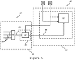
- Figure 7 illustrates an alternative option in which an estimated nacelle yaw position is calculated.
- the estimation module 80 includes the subtraction module 82, but also the averaging module 66. In this way, the estimation module 80 processes all of the absolute wind direction signals 64 received from the other wind turbines 4 in the wind farm 2 via the routing module 90 and outputs a single average absolute wind direction signal 65 to the subtraction module 82.
- the subtraction module 82 calculates and outputs an estimated nacelle yaw position signal 84 based on i) the relative wind direction signal 51 that is receives from the wind sensor 52 of the wind turbine 4, and ii) the averaged wind direction signal 65 received from the averaging module 66.
- the estimated nacelle yaw position signal 84 is then input directly to the control module 54 of the local controller 42 which is then able to disregard its internally calculated value of nacelle yaw position.
- the local controller and the wind farm controller include, if not explicitly stated here, appropriate processors, volatile and non-volatile memory, I/O interfaces and the like to implement the functionality that has been described.
- processors volatile and non-volatile memory, I/O interfaces and the like to implement the functionality that has been described.
- volatile and non-volatile memory volatile and non-volatile memory
- I/O interfaces I/O interfaces and the like to implement the functionality that has been described.
- the specific hardware and configuration required to implement the functionality is not part of the invention and is considered to be within the abilities of the skilled person or team.
- Figures 2 and 3 illustrate a 'part-centralised' implementation of a diagnostic process and an estimation process, respectively, that Figures 4 and 5 illustrate a 'fully-centralised' alternative implementation of those processes, and that Figures 6 and 7 illustrate a 'localised' implementation of those processes.
- the diagnostic process and the estimation process could be implemented as different approaches.
- the diagnostic process could be implemented as partly-centralised (i.e. Figure 2 ) and the estimation process could be implemented as fully-centralised.
Landscapes
- Engineering & Computer Science (AREA)
- Life Sciences & Earth Sciences (AREA)
- Sustainable Development (AREA)
- Sustainable Energy (AREA)
- Chemical & Material Sciences (AREA)
- Combustion & Propulsion (AREA)
- Mechanical Engineering (AREA)
- General Engineering & Computer Science (AREA)
- Physics & Mathematics (AREA)
- General Physics & Mathematics (AREA)
- Power Engineering (AREA)
- Wind Motors (AREA)
Claims (16)
- Verfahren zum Überprüfen eines Gondelnachführpositionssensors, der einer ersten Windturbine in einem Windpark zugeordnet ist, der eine Vielzahl anderer Windturbinen aufweist, wobei das Verfahren Folgendes umfasst:Bestimmen eines ersten absoluten Windrichtungssignals, das der ersten Windturbine zugeordnet ist;Bestimmen eines zweiten absoluten Windrichtungssignals, das der Vielzahl anderer Windturbinen zugeordnet ist;Vergleichen des ersten absoluten Windrichtungssignals mit dem zweiten Windrichtungssignal; undAusgeben eines Gondelnachführpositionssensor-Fehlersignals in dem Fall, dass das erste absolute Windrichtungssignal über einen vorbestimmten Fehlerbereich des zweiten Windrichtungssignals hinausgeht.
- Verfahren nach Anspruch 1, wobei das zweite absolute Windrichtungssignal eine absolute Mittelwert-Windrichtung für die Vielzahl anderer Windturbinen.
- Verfahren nach Anspruch 2, wobei das zweite Windrichtungssignal einen gewichteten Mittelwert darstellt.
- Verfahren nach einem der vorstehenden Ansprüche, wobei als Reaktion auf die Ausgabe des Fehlersignals das zweite absolute Windrichtungssignal verwendet wird, um ein geschätztes Gondelnachführpositionssignal zu bestimmen, das der ersten Windturbine zugeordnet ist.
- Verfahren nach Anspruch 4, wobei das geschätzte Gondelnachführpositionssignal durch Subtrahieren eines der ersten Turbine zugeordneten relativen Windrichtungssignals von dem zweiten absoluten Windrichtungssignal bestimmt wird.
- Verfahren nach Anspruch 4 oder 5, wobei das geschätzte Gondelnachführpositionssignal von einer Steuervorrichtung verwendet wird, die lokal zu der ersten Turbine ist, um die Nachführposition der Gondel zu steuern.
- Verfahren nach einem der vorstehenden Ansprüche, wobei das erste absolute Windrichtungssignal von einer lokalen Steuervorrichtung an der ersten Windturbine bestimmt wird.
- Verfahren nach Anspruch 7, wobei das erste absolute Windrichtungssignal durch Kombinieren eines Gondelpositionssignals und eines relativen Windrichtungssignals bestimmt wird.
- Verfahren nach Anspruch 7 oder 8, wobei der Vergleich des ersten und des zweiten absoluten Windrichtungssignals von der lokalen Steuervorrichtung durchgeführt wird.
- Verfahren nach einem der Ansprüche 7 bis 9, wobei das zweite absolute Windrichtungssignal von einer Windparksteuervorrichtung bestimmt und an die lokale Steuervorrichtung übertragen wird.
- Verfahren nach einem der Ansprüche 7 bis 9, wobei das zweite absolute Windrichtungssignal von der lokalen Steuervorrichtung bestimmt wird.
- Verfahren nach einem der Ansprüche 2 bis 6, wobei das erste absolute Windrichtungssignal von einer Windparksteuervorrichtung bestimmt wird.
- Verfahren nach Anspruch 12, wobei das zweite absolute Windrichtungssignal von der Windparksteuervorrichtung bestimmt wird, und wobei der Vergleich des ersten und des zweiten absoluten Windrichtungssignals von der Windparksteuervorrichtung durchgeführt wird, wodurch das Fehlersignal von der Windparksteuervorrichtung generiert wird und an die lokale Steuervorrichtung übertragen wird.
- Windpark mit einer ersten Windturbine und einer Vielzahl anderer Windturbinen, der eine Steuervorrichtung aufweist, die konfiguriert ist zum:Bestimmen eines ersten absoluten Windrichtungssignals, das der ersten Windturbine zugeordnet ist;Bestimmen eines zweiten absoluten Windrichtungssignals, das der Vielzahl anderer Windturbinen zugeordnet ist;Vergleichen des ersten absoluten Windrichtungssignals mit dem zweiten Windrichtungssignal; undAusgeben eines Gondelnachführpositionssensor-Fehlersignals in dem Fall, dass das erste absolute Windrichtungssignal über einen vorbestimmten Fehlerbereich des zweiten Windrichtungssignals hinausgeht.
- Steuervorrichtung für eine Windturbine oder einen Windpark, wobei die Steuervorrichtung konfiguriert ist zum:Bestimmen eines ersten absoluten Windrichtungssignals, das der ersten Windturbine zugeordnet ist;Bestimmen eines zweiten absoluten Windrichtungssignals, das der Vielzahl anderer Windturbinen zugeordnet ist;Vergleichen des ersten absoluten Windrichtungssignals mit dem zweiten Windrichtungssignal; undAusgeben eines Gondelnachführpositionssensor-Fehlersignals in dem Fall, dass das erste absolute Windrichtungssignal über einen vorbestimmten Fehlerbereich des zweiten Windrichtungssignals hinausgeht.
- Steuervorrichtung nach Anspruch 15, wobei beim Bestimmen des zweiten absoluten Windrichtungssignals die Steuervorrichtung konfiguriert ist, das zweite absolute Windrichtungssignal von einer zweiten Steuervorrichtung zu empfangen, die von ihr entfernt ist.
Priority Applications (1)
| Application Number | Priority Date | Filing Date | Title |
|---|---|---|---|
| EP17194978.7A EP3309389B1 (de) | 2014-09-29 | 2015-09-03 | Verifizierung von windturbinengondelgierpositionssensor |
Applications Claiming Priority (2)
| Application Number | Priority Date | Filing Date | Title |
|---|---|---|---|
| DKPA201470597 | 2014-09-29 | ||
| PCT/DK2015/050259 WO2016050249A1 (en) | 2014-09-29 | 2015-09-03 | Verification of wind turbine nacelle yaw position sensor |
Related Child Applications (2)
| Application Number | Title | Priority Date | Filing Date |
|---|---|---|---|
| EP17194978.7A Division EP3309389B1 (de) | 2014-09-29 | 2015-09-03 | Verifizierung von windturbinengondelgierpositionssensor |
| EP17194978.7A Division-Into EP3309389B1 (de) | 2014-09-29 | 2015-09-03 | Verifizierung von windturbinengondelgierpositionssensor |
Publications (2)
| Publication Number | Publication Date |
|---|---|
| EP3201465A1 EP3201465A1 (de) | 2017-08-09 |
| EP3201465B1 true EP3201465B1 (de) | 2018-11-07 |
Family
ID=59253319
Family Applications (2)
| Application Number | Title | Priority Date | Filing Date |
|---|---|---|---|
| EP15759376.5A Active EP3201465B1 (de) | 2014-09-29 | 2015-09-03 | Überprüfung eines azimutssensors einer windturbinegondel und azimutsteuerungssystem |
| EP17194978.7A Active EP3309389B1 (de) | 2014-09-29 | 2015-09-03 | Verifizierung von windturbinengondelgierpositionssensor |
Family Applications After (1)
| Application Number | Title | Priority Date | Filing Date |
|---|---|---|---|
| EP17194978.7A Active EP3309389B1 (de) | 2014-09-29 | 2015-09-03 | Verifizierung von windturbinengondelgierpositionssensor |
Country Status (5)
| Country | Link |
|---|---|
| US (1) | US10557459B2 (de) |
| EP (2) | EP3201465B1 (de) |
| CN (1) | CN106922162B (de) |
| ES (1) | ES2702475T3 (de) |
| WO (1) | WO2016050249A1 (de) |
Families Citing this family (20)
| Publication number | Priority date | Publication date | Assignee | Title |
|---|---|---|---|---|
| WO2015198793A1 (ja) | 2014-06-24 | 2015-12-30 | Ntn株式会社 | 状態監視システムおよびそれを用いた風力発電システム |
| CN106574606A (zh) * | 2014-07-29 | 2017-04-19 | Ntn株式会社 | 状态监视系统和具有该状态监视系统的风力发电系统 |
| CN105041570B (zh) * | 2015-07-30 | 2017-12-15 | 北京天诚同创电气有限公司 | 风电机组偏航控制方法和装置 |
| CN107304746B (zh) * | 2016-04-20 | 2020-07-17 | 北京天诚同创电气有限公司 | 风力发电机组及其运行控制方法与设备 |
| ES2899260T3 (es) | 2016-12-22 | 2022-03-10 | Vestas Wind Sys As | Método y controlador de generador de turbina eólica |
| CN110139982A (zh) * | 2016-12-22 | 2019-08-16 | 维斯塔斯风力系统集团公司 | 测量风力涡轮发电机中的换能器的电特性 |
| US10598148B2 (en) * | 2017-08-22 | 2020-03-24 | General Electric Company | System for controlling a yaw drive of a wind turbine when a native yaw drive control system is non-operational |
| US10662923B2 (en) * | 2017-09-29 | 2020-05-26 | General Electric Company | Contingency autonomous yaw control for a wind turbine |
| WO2019140614A1 (en) * | 2018-01-18 | 2019-07-25 | Abb Schweiz Ag | Method, apparatus and system for wind converter management |
| JP7101013B2 (ja) * | 2018-03-29 | 2022-07-14 | Ntn株式会社 | 風力発電所の監視システム |
| CN108979974A (zh) * | 2018-08-09 | 2018-12-11 | 绵阳鼎飞益电子科技有限公司 | 一种风力发电机组振动监测方法 |
| US12297805B2 (en) * | 2019-12-16 | 2025-05-13 | Vestas Wind Systems A/S | Yaw supervision |
| CN111664061B (zh) * | 2020-06-15 | 2021-12-17 | 三一重能有限公司 | 风力发电机组中偏航系统的故障诊断方法及装置 |
| CN111594397B (zh) * | 2020-06-22 | 2021-04-23 | 蒙东协合扎鲁特旗风力发电有限公司 | 一种风力发电机诊断装置及风力发电机 |
| CN111830279A (zh) * | 2020-08-05 | 2020-10-27 | 深圳市软筑信息技术有限公司 | 一种用于港口起重机的智能防风检测装置 |
| EP4232706B1 (de) | 2020-10-23 | 2024-07-31 | Vestas Wind Systems A/S | Giersteuerung einer windturbine mit mehreren rotoren |
| CN115683420A (zh) * | 2021-07-30 | 2023-02-03 | 北京金风科创风电设备有限公司 | 一种双转子风力发电机组的偏航传感器检测方法和相关装置 |
| CN114113683B (zh) * | 2021-11-02 | 2024-09-06 | 上海电气风电集团股份有限公司 | 风电场中风机风向仪的监测方法及其系统及计算机可读存储介质 |
| CN114856934B (zh) * | 2022-04-25 | 2025-07-08 | 许昌许继风电科技有限公司 | 一种风电机组偏航系统故障检测装置及方法 |
| US11952985B2 (en) * | 2022-06-16 | 2024-04-09 | Vestas Wind Systems A/S | Method for operating a cluster of wind turbines |
Citations (6)
| Publication number | Priority date | Publication date | Assignee | Title |
|---|---|---|---|---|
| US20080078228A1 (en) | 2006-09-29 | 2008-04-03 | Jaco Johannes Nies | Methods and apparatus for evaluating sensors and/or for controlling operation of an apparatus that includes a sensor |
| US20110098975A1 (en) | 2010-10-29 | 2011-04-28 | Maria Cecilia Mazzaro | Control system and methods of verifying operation of at least one wind turbine sensor |
| EP2520794A1 (de) | 2011-05-03 | 2012-11-07 | Siemens Aktiengesellschaft | Verfahren zum Prüfen einer Windturbine in einem Windpark auf Gier-Fehlausrichtung, Verfahren zur Überwachung einer Windturbine in einem Windpark und Überwachungsvorrichtung |
| EP2631471A1 (de) | 2012-02-24 | 2013-08-28 | Siemens Aktiengesellschaft | Windpark |
| US20130272878A1 (en) | 2010-12-30 | 2013-10-17 | Wei Zhu | System, Device, and Method for Adjusting Wind Turbine Component Workload |
| EP2728175A1 (de) | 2011-06-28 | 2014-05-07 | Mitsubishi Heavy Industries, Ltd. | Betriebsüberwachungssystem, betriebsüberwachungsverfahren und programm dafür |
Family Cites Families (23)
| Publication number | Priority date | Publication date | Assignee | Title |
|---|---|---|---|---|
| GB9706542D0 (en) * | 1997-04-01 | 1997-05-21 | Bennett Peter | Wind turbine yaw control and damping system |
| US20020029097A1 (en) * | 2000-04-07 | 2002-03-07 | Pionzio Dino J. | Wind farm control system |
| US6925385B2 (en) * | 2003-05-16 | 2005-08-02 | Seawest Holdings, Inc. | Wind power management system and method |
| CN101688517B (zh) * | 2007-01-17 | 2014-08-20 | 新世界一代股份有限公司 | 多发生器风轮机及操作方法 |
| JP4939286B2 (ja) | 2007-04-10 | 2012-05-23 | 三菱重工業株式会社 | 風力発電装置及びその制御方法 |
| WO2009068036A2 (en) * | 2007-11-30 | 2009-06-04 | Vestas Wind Systems A/S | A wind turbine, a method for controlling a wind turbine and use thereof |
| ES2524043T3 (es) * | 2008-03-07 | 2014-12-03 | Vestas Wind Systems A/S | Un sistema de control y un procedimiento para controlar una turbina eólica |
| JP5199828B2 (ja) | 2008-10-29 | 2013-05-15 | 三菱重工業株式会社 | 風力発電装置及びその制御方法 |
| US20100209246A1 (en) * | 2009-02-13 | 2010-08-19 | Robert Migliori | Yaw controller for downwind wind turbines |
| US8449255B2 (en) * | 2010-03-21 | 2013-05-28 | Btpatent Llc | Wind turbine blade system with air passageway |
| US8150641B2 (en) * | 2010-12-06 | 2012-04-03 | General Electric Company | System, device, and method for estimating possible power output of wind turbines |
| WO2013027127A2 (en) * | 2011-05-06 | 2013-02-28 | Condor Wind Energy Limited | Systems for minimizing yaw torque needed to control power output in two-bladed, teetering hinge wind turbines that control power output by yawing |
| US8977403B2 (en) * | 2011-06-22 | 2015-03-10 | Mitsubishi Heavy Industries, Ltd. | Remote monitoring apparatus, wind turbine generator system, and method of controlling remote monitoring apparatus |
| US9856855B2 (en) * | 2011-06-30 | 2018-01-02 | Vestas Wind Systems A/S | Disablement of wind turbines in a wind park |
| EP2742235B1 (de) * | 2011-08-11 | 2018-01-24 | Vestas Wind Systems A/S | Windkraftanlage und verfahren zur steuerung eines windturbinengenerators in der windkraftanlage |
| US9606518B2 (en) * | 2011-12-28 | 2017-03-28 | General Electric Company | Control system and method of predicting wind turbine power generation |
| TW201402940A (zh) * | 2012-02-08 | 2014-01-16 | Romo Wind Ag | 用於調整風力機之橫擺的裝置 |
| US9038901B2 (en) * | 2012-02-15 | 2015-05-26 | Burris Company, Inc. | Optical device having windage measurement instruments |
| EP2631470A1 (de) | 2012-02-23 | 2013-08-28 | Siemens Aktiengesellschaft | Verfahren zum Ausrichten des Windwinkels einer Windturbinengondel |
| US9574546B2 (en) | 2012-06-14 | 2017-02-21 | General Electric Company | Wind turbine rotor control |
| DE102012218484A1 (de) * | 2012-10-10 | 2014-04-10 | Wobben Properties Gmbh | Verfahren zum Betreiben einer Windenergieanlage |
| CN104021424B (zh) * | 2013-02-28 | 2018-12-07 | 乌托巴斯洞察公司 | 用于预测风场中的风机的输出功率的方法和装置 |
| ES2812808T3 (es) * | 2016-02-12 | 2021-03-18 | Vestas Wind Sys As | Mejoras en relación con un sensor de guiñada para una turbina eólica |
-
2015
- 2015-09-03 EP EP15759376.5A patent/EP3201465B1/de active Active
- 2015-09-03 US US15/508,267 patent/US10557459B2/en active Active
- 2015-09-03 CN CN201580052303.0A patent/CN106922162B/zh active Active
- 2015-09-03 EP EP17194978.7A patent/EP3309389B1/de active Active
- 2015-09-03 WO PCT/DK2015/050259 patent/WO2016050249A1/en not_active Ceased
- 2015-09-03 ES ES15759376T patent/ES2702475T3/es active Active
Patent Citations (6)
| Publication number | Priority date | Publication date | Assignee | Title |
|---|---|---|---|---|
| US20080078228A1 (en) | 2006-09-29 | 2008-04-03 | Jaco Johannes Nies | Methods and apparatus for evaluating sensors and/or for controlling operation of an apparatus that includes a sensor |
| US20110098975A1 (en) | 2010-10-29 | 2011-04-28 | Maria Cecilia Mazzaro | Control system and methods of verifying operation of at least one wind turbine sensor |
| US20130272878A1 (en) | 2010-12-30 | 2013-10-17 | Wei Zhu | System, Device, and Method for Adjusting Wind Turbine Component Workload |
| EP2520794A1 (de) | 2011-05-03 | 2012-11-07 | Siemens Aktiengesellschaft | Verfahren zum Prüfen einer Windturbine in einem Windpark auf Gier-Fehlausrichtung, Verfahren zur Überwachung einer Windturbine in einem Windpark und Überwachungsvorrichtung |
| EP2728175A1 (de) | 2011-06-28 | 2014-05-07 | Mitsubishi Heavy Industries, Ltd. | Betriebsüberwachungssystem, betriebsüberwachungsverfahren und programm dafür |
| EP2631471A1 (de) | 2012-02-24 | 2013-08-28 | Siemens Aktiengesellschaft | Windpark |
Non-Patent Citations (1)
| Title |
|---|
| RETHORE, PIERRE-ELOUAN MIKAEL ET AL.: "Systematic Wind Farm Measurement Data Filtering Tool for Wake Model Calibration", EOW CONFERENCE 2009, 2009, pages 1 - 10, XP055627709, Retrieved from the Internet <URL:https://orbit.dtu.dk/files/6410426/frandsen2_offshore_paper.pdf> |
Also Published As
| Publication number | Publication date |
|---|---|
| EP3309389B1 (de) | 2019-08-14 |
| CN106922162B (zh) | 2019-04-23 |
| US10557459B2 (en) | 2020-02-11 |
| US20170241409A1 (en) | 2017-08-24 |
| CN106922162A (zh) | 2017-07-04 |
| WO2016050249A1 (en) | 2016-04-07 |
| EP3309389A1 (de) | 2018-04-18 |
| ES2702475T3 (es) | 2019-03-01 |
| EP3201465A1 (de) | 2017-08-09 |
Similar Documents
| Publication | Publication Date | Title |
|---|---|---|
| EP3201465B1 (de) | Überprüfung eines azimutssensors einer windturbinegondel und azimutsteuerungssystem | |
| EP2940295B1 (de) | System und verfahren zur steuerung einer windenergieanlage | |
| US9366230B2 (en) | System and method for reducing loads acting on a wind turbine in response to transient wind conditions | |
| US11242841B2 (en) | System and method for controlling a wind turbine based on a collective pitch-offset | |
| US9841004B2 (en) | Yaw control system and yaw control method for wind turbine generator | |
| Zhang et al. | Fault detection and isolation of the wind turbine benchmark: An estimation-based approach | |
| US20120024053A1 (en) | System and method for detecting ice on a wind turbine rotor blade | |
| US10774810B2 (en) | System and method for estimating high bandwidth tower deflection for wind turbines | |
| US9581141B2 (en) | Early detection of wind turbine degradation using acoustical monitoring | |
| WO2018006849A1 (en) | Wind turbine and method of operating wind turbine | |
| EP4083421A1 (de) | System und verfahren zur schlupferkennung und überwachung des oberflächenzustands in einer schlupfkupplung einer drehwelle | |
| WO2016138647A1 (en) | System and method for mitigating loads on a wind turbine | |
| EP3051127A1 (de) | Windturbinenvorrichtung, anomalienerkennungsvorrichtung für die windturbinenvorrichtung und anomalienerkennungsverfahren für die windturbinenvorrichtung | |
| CN105041571A (zh) | 预测风速风向的智能控制系统及其控制方法 | |
| DK201770756A1 (en) | System and method of controlling an electronic component of a wind turbine using contingency communications | |
| EP3844388B1 (de) | Auslöseverkürzungswerkzeug für ein windenergieanlagesystem | |
| CA3206271A1 (en) | System and method for detecting and responding to rotor blade damage in a wind turbine |
Legal Events
| Date | Code | Title | Description |
|---|---|---|---|
| STAA | Information on the status of an ep patent application or granted ep patent |
Free format text: STATUS: THE INTERNATIONAL PUBLICATION HAS BEEN MADE |
|
| PUAI | Public reference made under article 153(3) epc to a published international application that has entered the european phase |
Free format text: ORIGINAL CODE: 0009012 |
|
| STAA | Information on the status of an ep patent application or granted ep patent |
Free format text: STATUS: REQUEST FOR EXAMINATION WAS MADE |
|
| 17P | Request for examination filed |
Effective date: 20170303 |
|
| AK | Designated contracting states |
Kind code of ref document: A1 Designated state(s): AL AT BE BG CH CY CZ DE DK EE ES FI FR GB GR HR HU IE IS IT LI LT LU LV MC MK MT NL NO PL PT RO RS SE SI SK SM TR |
|
| AX | Request for extension of the european patent |
Extension state: BA ME |
|
| DAV | Request for validation of the european patent (deleted) | ||
| DAX | Request for extension of the european patent (deleted) | ||
| REG | Reference to a national code |
Ref country code: DE Ref legal event code: R079 Ref document number: 602015019556 Country of ref document: DE Free format text: PREVIOUS MAIN CLASS: F03D0007040000 Ipc: F03D0017000000 |
|
| GRAP | Despatch of communication of intention to grant a patent |
Free format text: ORIGINAL CODE: EPIDOSNIGR1 |
|
| STAA | Information on the status of an ep patent application or granted ep patent |
Free format text: STATUS: GRANT OF PATENT IS INTENDED |
|
| RIC1 | Information provided on ipc code assigned before grant |
Ipc: F03D 7/04 20060101ALI20180604BHEP Ipc: F03D 17/00 20160101AFI20180604BHEP Ipc: F03D 9/00 20160101ALI20180604BHEP Ipc: F03D 7/02 20060101ALI20180604BHEP |
|
| INTG | Intention to grant announced |
Effective date: 20180626 |
|
| GRAS | Grant fee paid |
Free format text: ORIGINAL CODE: EPIDOSNIGR3 |
|
| GRAJ | Information related to disapproval of communication of intention to grant by the applicant or resumption of examination proceedings by the epo deleted |
Free format text: ORIGINAL CODE: EPIDOSDIGR1 |
|
| GRAL | Information related to payment of fee for publishing/printing deleted |
Free format text: ORIGINAL CODE: EPIDOSDIGR3 |
|
| STAA | Information on the status of an ep patent application or granted ep patent |
Free format text: STATUS: REQUEST FOR EXAMINATION WAS MADE |
|
| GRAR | Information related to intention to grant a patent recorded |
Free format text: ORIGINAL CODE: EPIDOSNIGR71 |
|
| STAA | Information on the status of an ep patent application or granted ep patent |
Free format text: STATUS: GRANT OF PATENT IS INTENDED |
|
| GRAA | (expected) grant |
Free format text: ORIGINAL CODE: 0009210 |
|
| STAA | Information on the status of an ep patent application or granted ep patent |
Free format text: STATUS: THE PATENT HAS BEEN GRANTED |
|
| INTG | Intention to grant announced |
Effective date: 20180905 |
|
| AK | Designated contracting states |
Kind code of ref document: B1 Designated state(s): AL AT BE BG CH CY CZ DE DK EE ES FI FR GB GR HR HU IE IS IT LI LT LU LV MC MK MT NL NO PL PT RO RS SE SI SK SM TR |
|
| REG | Reference to a national code |
Ref country code: GB Ref legal event code: FG4D |
|
| REG | Reference to a national code |
Ref country code: CH Ref legal event code: EP Ref country code: AT Ref legal event code: REF Ref document number: 1062357 Country of ref document: AT Kind code of ref document: T Effective date: 20181115 |
|
| REG | Reference to a national code |
Ref country code: DE Ref legal event code: R096 Ref document number: 602015019556 Country of ref document: DE |
|
| REG | Reference to a national code |
Ref country code: IE Ref legal event code: FG4D |
|
| REG | Reference to a national code |
Ref country code: ES Ref legal event code: FG2A Ref document number: 2702475 Country of ref document: ES Kind code of ref document: T3 Effective date: 20190301 |
|
| REG | Reference to a national code |
Ref country code: NL Ref legal event code: MP Effective date: 20181107 |
|
| REG | Reference to a national code |
Ref country code: LT Ref legal event code: MG4D |
|
| REG | Reference to a national code |
Ref country code: AT Ref legal event code: MK05 Ref document number: 1062357 Country of ref document: AT Kind code of ref document: T Effective date: 20181107 |
|
| PG25 | Lapsed in a contracting state [announced via postgrant information from national office to epo] |
Ref country code: FI Free format text: LAPSE BECAUSE OF FAILURE TO SUBMIT A TRANSLATION OF THE DESCRIPTION OR TO PAY THE FEE WITHIN THE PRESCRIBED TIME-LIMIT Effective date: 20181107 Ref country code: LV Free format text: LAPSE BECAUSE OF FAILURE TO SUBMIT A TRANSLATION OF THE DESCRIPTION OR TO PAY THE FEE WITHIN THE PRESCRIBED TIME-LIMIT Effective date: 20181107 Ref country code: AT Free format text: LAPSE BECAUSE OF FAILURE TO SUBMIT A TRANSLATION OF THE DESCRIPTION OR TO PAY THE FEE WITHIN THE PRESCRIBED TIME-LIMIT Effective date: 20181107 Ref country code: HR Free format text: LAPSE BECAUSE OF FAILURE TO SUBMIT A TRANSLATION OF THE DESCRIPTION OR TO PAY THE FEE WITHIN THE PRESCRIBED TIME-LIMIT Effective date: 20181107 Ref country code: BG Free format text: LAPSE BECAUSE OF FAILURE TO SUBMIT A TRANSLATION OF THE DESCRIPTION OR TO PAY THE FEE WITHIN THE PRESCRIBED TIME-LIMIT Effective date: 20190207 Ref country code: NO Free format text: LAPSE BECAUSE OF FAILURE TO SUBMIT A TRANSLATION OF THE DESCRIPTION OR TO PAY THE FEE WITHIN THE PRESCRIBED TIME-LIMIT Effective date: 20190207 Ref country code: LT Free format text: LAPSE BECAUSE OF FAILURE TO SUBMIT A TRANSLATION OF THE DESCRIPTION OR TO PAY THE FEE WITHIN THE PRESCRIBED TIME-LIMIT Effective date: 20181107 Ref country code: IS Free format text: LAPSE BECAUSE OF FAILURE TO SUBMIT A TRANSLATION OF THE DESCRIPTION OR TO PAY THE FEE WITHIN THE PRESCRIBED TIME-LIMIT Effective date: 20190307 |
|
| PG25 | Lapsed in a contracting state [announced via postgrant information from national office to epo] |
Ref country code: AL Free format text: LAPSE BECAUSE OF FAILURE TO SUBMIT A TRANSLATION OF THE DESCRIPTION OR TO PAY THE FEE WITHIN THE PRESCRIBED TIME-LIMIT Effective date: 20181107 Ref country code: PT Free format text: LAPSE BECAUSE OF FAILURE TO SUBMIT A TRANSLATION OF THE DESCRIPTION OR TO PAY THE FEE WITHIN THE PRESCRIBED TIME-LIMIT Effective date: 20190307 Ref country code: NL Free format text: LAPSE BECAUSE OF FAILURE TO SUBMIT A TRANSLATION OF THE DESCRIPTION OR TO PAY THE FEE WITHIN THE PRESCRIBED TIME-LIMIT Effective date: 20181107 Ref country code: GR Free format text: LAPSE BECAUSE OF FAILURE TO SUBMIT A TRANSLATION OF THE DESCRIPTION OR TO PAY THE FEE WITHIN THE PRESCRIBED TIME-LIMIT Effective date: 20190208 Ref country code: SE Free format text: LAPSE BECAUSE OF FAILURE TO SUBMIT A TRANSLATION OF THE DESCRIPTION OR TO PAY THE FEE WITHIN THE PRESCRIBED TIME-LIMIT Effective date: 20181107 Ref country code: RS Free format text: LAPSE BECAUSE OF FAILURE TO SUBMIT A TRANSLATION OF THE DESCRIPTION OR TO PAY THE FEE WITHIN THE PRESCRIBED TIME-LIMIT Effective date: 20181107 |
|
| PG25 | Lapsed in a contracting state [announced via postgrant information from national office to epo] |
Ref country code: CZ Free format text: LAPSE BECAUSE OF FAILURE TO SUBMIT A TRANSLATION OF THE DESCRIPTION OR TO PAY THE FEE WITHIN THE PRESCRIBED TIME-LIMIT Effective date: 20181107 Ref country code: IT Free format text: LAPSE BECAUSE OF FAILURE TO SUBMIT A TRANSLATION OF THE DESCRIPTION OR TO PAY THE FEE WITHIN THE PRESCRIBED TIME-LIMIT Effective date: 20181107 Ref country code: DK Free format text: LAPSE BECAUSE OF FAILURE TO SUBMIT A TRANSLATION OF THE DESCRIPTION OR TO PAY THE FEE WITHIN THE PRESCRIBED TIME-LIMIT Effective date: 20181107 Ref country code: PL Free format text: LAPSE BECAUSE OF FAILURE TO SUBMIT A TRANSLATION OF THE DESCRIPTION OR TO PAY THE FEE WITHIN THE PRESCRIBED TIME-LIMIT Effective date: 20181107 |
|
| REG | Reference to a national code |
Ref country code: DE Ref legal event code: R026 Ref document number: 602015019556 Country of ref document: DE |
|
| PLBI | Opposition filed |
Free format text: ORIGINAL CODE: 0009260 |
|
| PLAX | Notice of opposition and request to file observation + time limit sent |
Free format text: ORIGINAL CODE: EPIDOSNOBS2 |
|
| PG25 | Lapsed in a contracting state [announced via postgrant information from national office to epo] |
Ref country code: SM Free format text: LAPSE BECAUSE OF FAILURE TO SUBMIT A TRANSLATION OF THE DESCRIPTION OR TO PAY THE FEE WITHIN THE PRESCRIBED TIME-LIMIT Effective date: 20181107 Ref country code: EE Free format text: LAPSE BECAUSE OF FAILURE TO SUBMIT A TRANSLATION OF THE DESCRIPTION OR TO PAY THE FEE WITHIN THE PRESCRIBED TIME-LIMIT Effective date: 20181107 Ref country code: SK Free format text: LAPSE BECAUSE OF FAILURE TO SUBMIT A TRANSLATION OF THE DESCRIPTION OR TO PAY THE FEE WITHIN THE PRESCRIBED TIME-LIMIT Effective date: 20181107 Ref country code: RO Free format text: LAPSE BECAUSE OF FAILURE TO SUBMIT A TRANSLATION OF THE DESCRIPTION OR TO PAY THE FEE WITHIN THE PRESCRIBED TIME-LIMIT Effective date: 20181107 |
|
| 26 | Opposition filed |
Opponent name: SIEMENS GAMESA RENEWABLE ENERGY GMBH & CO. KG Effective date: 20190807 |
|
| PG25 | Lapsed in a contracting state [announced via postgrant information from national office to epo] |
Ref country code: SI Free format text: LAPSE BECAUSE OF FAILURE TO SUBMIT A TRANSLATION OF THE DESCRIPTION OR TO PAY THE FEE WITHIN THE PRESCRIBED TIME-LIMIT Effective date: 20181107 |
|
| PLAK | Information related to reply of patent proprietor to notice(s) of opposition modified |
Free format text: ORIGINAL CODE: EPIDOSCOBS3 |
|
| PLBB | Reply of patent proprietor to notice(s) of opposition received |
Free format text: ORIGINAL CODE: EPIDOSNOBS3 |
|
| PG25 | Lapsed in a contracting state [announced via postgrant information from national office to epo] |
Ref country code: TR Free format text: LAPSE BECAUSE OF FAILURE TO SUBMIT A TRANSLATION OF THE DESCRIPTION OR TO PAY THE FEE WITHIN THE PRESCRIBED TIME-LIMIT Effective date: 20181107 |
|
| PG25 | Lapsed in a contracting state [announced via postgrant information from national office to epo] |
Ref country code: MC Free format text: LAPSE BECAUSE OF FAILURE TO SUBMIT A TRANSLATION OF THE DESCRIPTION OR TO PAY THE FEE WITHIN THE PRESCRIBED TIME-LIMIT Effective date: 20181107 |
|
| REG | Reference to a national code |
Ref country code: CH Ref legal event code: PL |
|
| PG25 | Lapsed in a contracting state [announced via postgrant information from national office to epo] |
Ref country code: IE Free format text: LAPSE BECAUSE OF NON-PAYMENT OF DUE FEES Effective date: 20190903 Ref country code: LI Free format text: LAPSE BECAUSE OF NON-PAYMENT OF DUE FEES Effective date: 20190930 Ref country code: CH Free format text: LAPSE BECAUSE OF NON-PAYMENT OF DUE FEES Effective date: 20190930 Ref country code: LU Free format text: LAPSE BECAUSE OF NON-PAYMENT OF DUE FEES Effective date: 20190903 |
|
| REG | Reference to a national code |
Ref country code: BE Ref legal event code: MM Effective date: 20190930 |
|
| PG25 | Lapsed in a contracting state [announced via postgrant information from national office to epo] |
Ref country code: BE Free format text: LAPSE BECAUSE OF NON-PAYMENT OF DUE FEES Effective date: 20190930 |
|
| PLBP | Opposition withdrawn |
Free format text: ORIGINAL CODE: 0009264 |
|
| PLBD | Termination of opposition procedure: decision despatched |
Free format text: ORIGINAL CODE: EPIDOSNOPC1 |
|
| REG | Reference to a national code |
Ref country code: DE Ref legal event code: R100 Ref document number: 602015019556 Country of ref document: DE |
|
| PG25 | Lapsed in a contracting state [announced via postgrant information from national office to epo] |
Ref country code: CY Free format text: LAPSE BECAUSE OF FAILURE TO SUBMIT A TRANSLATION OF THE DESCRIPTION OR TO PAY THE FEE WITHIN THE PRESCRIBED TIME-LIMIT Effective date: 20181107 |
|
| PLBM | Termination of opposition procedure: date of legal effect published |
Free format text: ORIGINAL CODE: 0009276 |
|
| 27C | Opposition proceedings terminated |
Effective date: 20210322 |
|
| PG25 | Lapsed in a contracting state [announced via postgrant information from national office to epo] |
Ref country code: HU Free format text: LAPSE BECAUSE OF FAILURE TO SUBMIT A TRANSLATION OF THE DESCRIPTION OR TO PAY THE FEE WITHIN THE PRESCRIBED TIME-LIMIT; INVALID AB INITIO Effective date: 20150903 Ref country code: MT Free format text: LAPSE BECAUSE OF FAILURE TO SUBMIT A TRANSLATION OF THE DESCRIPTION OR TO PAY THE FEE WITHIN THE PRESCRIBED TIME-LIMIT Effective date: 20181107 |
|
| PG25 | Lapsed in a contracting state [announced via postgrant information from national office to epo] |
Ref country code: MK Free format text: LAPSE BECAUSE OF FAILURE TO SUBMIT A TRANSLATION OF THE DESCRIPTION OR TO PAY THE FEE WITHIN THE PRESCRIBED TIME-LIMIT Effective date: 20181107 |
|
| P01 | Opt-out of the competence of the unified patent court (upc) registered |
Effective date: 20230521 |
|
| PGFP | Annual fee paid to national office [announced via postgrant information from national office to epo] |
Ref country code: ES Payment date: 20241021 Year of fee payment: 10 |
|
| PGFP | Annual fee paid to national office [announced via postgrant information from national office to epo] |
Ref country code: DE Payment date: 20250926 Year of fee payment: 11 |
|
| PGFP | Annual fee paid to national office [announced via postgrant information from national office to epo] |
Ref country code: GB Payment date: 20250923 Year of fee payment: 11 |
|
| PGFP | Annual fee paid to national office [announced via postgrant information from national office to epo] |
Ref country code: FR Payment date: 20250925 Year of fee payment: 11 |