EP3201374B1 - Procédé et dispositif de régulation de l'activité d'un système bioélectrochimique comportant à la fois une bioanode et une biocathode - Google Patents
Procédé et dispositif de régulation de l'activité d'un système bioélectrochimique comportant à la fois une bioanode et une biocathode Download PDFInfo
- Publication number
- EP3201374B1 EP3201374B1 EP15787256.5A EP15787256A EP3201374B1 EP 3201374 B1 EP3201374 B1 EP 3201374B1 EP 15787256 A EP15787256 A EP 15787256A EP 3201374 B1 EP3201374 B1 EP 3201374B1
- Authority
- EP
- European Patent Office
- Prior art keywords
- biocathode
- bioanode
- electrolyte
- anode
- compartment
- Prior art date
- Legal status (The legal status is an assumption and is not a legal conclusion. Google has not performed a legal analysis and makes no representation as to the accuracy of the status listed.)
- Active
Links
- 238000000034 method Methods 0.000 title claims description 23
- 230000000694 effects Effects 0.000 title claims description 19
- 239000003792 electrolyte Substances 0.000 claims description 57
- 230000033228 biological regulation Effects 0.000 claims description 37
- VNWKTOKETHGBQD-UHFFFAOYSA-N methane Chemical compound C VNWKTOKETHGBQD-UHFFFAOYSA-N 0.000 claims description 21
- 239000013626 chemical specie Substances 0.000 claims description 18
- 238000005457 optimization Methods 0.000 claims description 15
- 238000004519 manufacturing process Methods 0.000 claims description 13
- 239000012528 membrane Substances 0.000 claims description 13
- 239000000126 substance Substances 0.000 claims description 13
- 238000005086 pumping Methods 0.000 claims description 10
- QTBSBXVTEAMEQO-UHFFFAOYSA-M Acetate Chemical compound CC([O-])=O QTBSBXVTEAMEQO-UHFFFAOYSA-M 0.000 claims description 9
- OKTJSMMVPCPJKN-UHFFFAOYSA-N Carbon Chemical compound [C] OKTJSMMVPCPJKN-UHFFFAOYSA-N 0.000 claims description 9
- 244000005700 microbiome Species 0.000 claims description 9
- 239000000523 sample Substances 0.000 claims description 9
- UFHFLCQGNIYNRP-UHFFFAOYSA-N Hydrogen Chemical compound [H][H] UFHFLCQGNIYNRP-UHFFFAOYSA-N 0.000 claims description 8
- 230000004071 biological effect Effects 0.000 claims description 8
- 230000001105 regulatory effect Effects 0.000 claims description 8
- 229910052739 hydrogen Inorganic materials 0.000 claims description 7
- 239000001257 hydrogen Substances 0.000 claims description 7
- 238000005341 cation exchange Methods 0.000 claims description 6
- JVTAAEKCZFNVCJ-UHFFFAOYSA-M Lactate Chemical compound CC(O)C([O-])=O JVTAAEKCZFNVCJ-UHFFFAOYSA-M 0.000 claims description 5
- 238000006073 displacement reaction Methods 0.000 claims description 5
- 239000007789 gas Substances 0.000 claims description 5
- XBDQKXXYIPTUBI-UHFFFAOYSA-M Propionate Chemical compound CCC([O-])=O XBDQKXXYIPTUBI-UHFFFAOYSA-M 0.000 claims description 4
- 238000007254 oxidation reaction Methods 0.000 claims description 4
- 229910052799 carbon Inorganic materials 0.000 claims description 3
- 238000005868 electrolysis reaction Methods 0.000 claims description 3
- 230000003647 oxidation Effects 0.000 claims description 3
- XLYOFNOQVPJJNP-UHFFFAOYSA-N water Substances O XLYOFNOQVPJJNP-UHFFFAOYSA-N 0.000 claims description 3
- 230000001276 controlling effect Effects 0.000 claims description 2
- 150000007524 organic acids Chemical class 0.000 claims description 2
- 150000003839 salts Chemical class 0.000 claims description 2
- 239000000725 suspension Substances 0.000 claims description 2
- 239000000758 substrate Substances 0.000 description 18
- QTBSBXVTEAMEQO-UHFFFAOYSA-N Acetic acid Chemical compound CC(O)=O QTBSBXVTEAMEQO-UHFFFAOYSA-N 0.000 description 12
- 238000002474 experimental method Methods 0.000 description 12
- 235000014113 dietary fatty acids Nutrition 0.000 description 8
- 229930195729 fatty acid Natural products 0.000 description 8
- 239000000194 fatty acid Substances 0.000 description 8
- 150000004665 fatty acids Chemical class 0.000 description 8
- 229910002804 graphite Inorganic materials 0.000 description 6
- 239000010439 graphite Substances 0.000 description 6
- 230000000813 microbial effect Effects 0.000 description 6
- 238000011081 inoculation Methods 0.000 description 5
- 239000012071 phase Substances 0.000 description 5
- FERIUCNNQQJTOY-UHFFFAOYSA-N Butyric acid Natural products CCCC(O)=O FERIUCNNQQJTOY-UHFFFAOYSA-N 0.000 description 4
- BDAGIHXWWSANSR-UHFFFAOYSA-M Formate Chemical compound [O-]C=O BDAGIHXWWSANSR-UHFFFAOYSA-M 0.000 description 4
- 238000010586 diagram Methods 0.000 description 4
- ZOMNIUBKTOKEHS-UHFFFAOYSA-L dimercury dichloride Chemical class Cl[Hg][Hg]Cl ZOMNIUBKTOKEHS-UHFFFAOYSA-L 0.000 description 4
- 239000008187 granular material Substances 0.000 description 4
- JVTAAEKCZFNVCJ-UHFFFAOYSA-N lactic acid Chemical compound CC(O)C(O)=O JVTAAEKCZFNVCJ-UHFFFAOYSA-N 0.000 description 4
- NQPDZGIKBAWPEJ-UHFFFAOYSA-N valeric acid Chemical compound CCCCC(O)=O NQPDZGIKBAWPEJ-UHFFFAOYSA-N 0.000 description 4
- QVGXLLKOCUKJST-UHFFFAOYSA-N atomic oxygen Chemical compound [O] QVGXLLKOCUKJST-UHFFFAOYSA-N 0.000 description 3
- 239000000203 mixture Substances 0.000 description 3
- 229910052760 oxygen Inorganic materials 0.000 description 3
- 239000001301 oxygen Substances 0.000 description 3
- OQFSYHWITGFERZ-UHFFFAOYSA-M 2-bromoethanesulfonate Chemical compound [O-]S(=O)(=O)CCBr OQFSYHWITGFERZ-UHFFFAOYSA-M 0.000 description 2
- 241000894006 Bacteria Species 0.000 description 2
- FERIUCNNQQJTOY-UHFFFAOYSA-M Butyrate Chemical compound CCCC([O-])=O FERIUCNNQQJTOY-UHFFFAOYSA-M 0.000 description 2
- 229920000049 Carbon (fiber) Polymers 0.000 description 2
- 229910000831 Steel Inorganic materials 0.000 description 2
- 239000002253 acid Substances 0.000 description 2
- 150000007513 acids Chemical class 0.000 description 2
- 238000006243 chemical reaction Methods 0.000 description 2
- 230000002596 correlated effect Effects 0.000 description 2
- 230000001186 cumulative effect Effects 0.000 description 2
- XBDQKXXYIPTUBI-UHFFFAOYSA-N dimethylselenoniopropionate Natural products CCC(O)=O XBDQKXXYIPTUBI-UHFFFAOYSA-N 0.000 description 2
- 238000004817 gas chromatography Methods 0.000 description 2
- 150000002431 hydrogen Chemical class 0.000 description 2
- 238000002347 injection Methods 0.000 description 2
- 239000007924 injection Substances 0.000 description 2
- 239000004310 lactic acid Substances 0.000 description 2
- 235000014655 lactic acid Nutrition 0.000 description 2
- 239000007788 liquid Substances 0.000 description 2
- 239000000463 material Substances 0.000 description 2
- BDAGIHXWWSANSR-UHFFFAOYSA-N methanoic acid Natural products OC=O BDAGIHXWWSANSR-UHFFFAOYSA-N 0.000 description 2
- 230000004048 modification Effects 0.000 description 2
- 238000012986 modification Methods 0.000 description 2
- 239000007787 solid Substances 0.000 description 2
- 239000010959 steel Substances 0.000 description 2
- VDZOOKBUILJEDG-UHFFFAOYSA-M tetrabutylammonium hydroxide Chemical compound [OH-].CCCC[N+](CCCC)(CCCC)CCCC VDZOOKBUILJEDG-UHFFFAOYSA-M 0.000 description 2
- 229940070710 valerate Drugs 0.000 description 2
- 239000002699 waste material Substances 0.000 description 2
- HNSDLXPSAYFUHK-UHFFFAOYSA-N 1,4-bis(2-ethylhexyl) sulfosuccinate Chemical compound CCCCC(CC)COC(=O)CC(S(O)(=O)=O)C(=O)OCC(CC)CCCC HNSDLXPSAYFUHK-UHFFFAOYSA-N 0.000 description 1
- OSWFIVFLDKOXQC-UHFFFAOYSA-N 4-(3-methoxyphenyl)aniline Chemical compound COC1=CC=CC(C=2C=CC(N)=CC=2)=C1 OSWFIVFLDKOXQC-UHFFFAOYSA-N 0.000 description 1
- 239000002028 Biomass Substances 0.000 description 1
- 101100317222 Borrelia hermsii vsp3 gene Proteins 0.000 description 1
- 230000010718 Oxidation Activity Effects 0.000 description 1
- 230000000789 acetogenic effect Effects 0.000 description 1
- 238000005349 anion exchange Methods 0.000 description 1
- 230000006399 behavior Effects 0.000 description 1
- 230000015572 biosynthetic process Effects 0.000 description 1
- 150000004649 carbonic acid derivatives Chemical class 0.000 description 1
- 238000004624 confocal microscopy Methods 0.000 description 1
- 230000000875 corresponding effect Effects 0.000 description 1
- 230000008878 coupling Effects 0.000 description 1
- 238000010168 coupling process Methods 0.000 description 1
- 238000005859 coupling reaction Methods 0.000 description 1
- 230000007423 decrease Effects 0.000 description 1
- 230000009977 dual effect Effects 0.000 description 1
- 239000003480 eluent Substances 0.000 description 1
- 229940082150 encore Drugs 0.000 description 1
- 235000019253 formic acid Nutrition 0.000 description 1
- 230000014509 gene expression Effects 0.000 description 1
- 239000011521 glass Substances 0.000 description 1
- 230000002779 inactivation Effects 0.000 description 1
- 239000002440 industrial waste Substances 0.000 description 1
- 238000004255 ion exchange chromatography Methods 0.000 description 1
- 239000003014 ion exchange membrane Substances 0.000 description 1
- 239000007791 liquid phase Substances 0.000 description 1
- 238000000386 microscopy Methods 0.000 description 1
- WWZKQHOCKIZLMA-UHFFFAOYSA-M octanoate Chemical compound CCCCCCCC([O-])=O WWZKQHOCKIZLMA-UHFFFAOYSA-M 0.000 description 1
- 239000005416 organic matter Substances 0.000 description 1
- 239000010815 organic waste Substances 0.000 description 1
- YPJUNDFVDDCYIH-UHFFFAOYSA-N perfluorobutyric acid Chemical compound OC(=O)C(F)(F)C(F)(F)C(F)(F)F YPJUNDFVDDCYIH-UHFFFAOYSA-N 0.000 description 1
- BASFCYQUMIYNBI-UHFFFAOYSA-N platinum Chemical compound [Pt] BASFCYQUMIYNBI-UHFFFAOYSA-N 0.000 description 1
- 235000019260 propionic acid Nutrition 0.000 description 1
- IUVKMZGDUIUOCP-BTNSXGMBSA-N quinbolone Chemical compound O([C@H]1CC[C@H]2[C@H]3[C@@H]([C@]4(C=CC(=O)C=C4CC3)C)CC[C@@]21C)C1=CCCC1 IUVKMZGDUIUOCP-BTNSXGMBSA-N 0.000 description 1
- 238000011084 recovery Methods 0.000 description 1
- 238000006722 reduction reaction Methods 0.000 description 1
- 239000010802 sludge Substances 0.000 description 1
- 229910001220 stainless steel Inorganic materials 0.000 description 1
- 239000010935 stainless steel Substances 0.000 description 1
- 229910052717 sulfur Inorganic materials 0.000 description 1
- 230000001360 synchronised effect Effects 0.000 description 1
- 229940005605 valeric acid Drugs 0.000 description 1
Images


Classifications
-
- C—CHEMISTRY; METALLURGY
- C25—ELECTROLYTIC OR ELECTROPHORETIC PROCESSES; APPARATUS THEREFOR
- C25B—ELECTROLYTIC OR ELECTROPHORETIC PROCESSES FOR THE PRODUCTION OF COMPOUNDS OR NON-METALS; APPARATUS THEREFOR
- C25B15/00—Operating or servicing cells
- C25B15/02—Process control or regulation
-
- C—CHEMISTRY; METALLURGY
- C12—BIOCHEMISTRY; BEER; SPIRITS; WINE; VINEGAR; MICROBIOLOGY; ENZYMOLOGY; MUTATION OR GENETIC ENGINEERING
- C12M—APPARATUS FOR ENZYMOLOGY OR MICROBIOLOGY; APPARATUS FOR CULTURING MICROORGANISMS FOR PRODUCING BIOMASS, FOR GROWING CELLS OR FOR OBTAINING FERMENTATION OR METABOLIC PRODUCTS, i.e. BIOREACTORS OR FERMENTERS
- C12M41/00—Means for regulation, monitoring, measurement or control, e.g. flow regulation
- C12M41/48—Automatic or computerized control
-
- C—CHEMISTRY; METALLURGY
- C25—ELECTROLYTIC OR ELECTROPHORETIC PROCESSES; APPARATUS THEREFOR
- C25B—ELECTROLYTIC OR ELECTROPHORETIC PROCESSES FOR THE PRODUCTION OF COMPOUNDS OR NON-METALS; APPARATUS THEREFOR
- C25B1/00—Electrolytic production of inorganic compounds or non-metals
- C25B1/01—Products
- C25B1/02—Hydrogen or oxygen
-
- C—CHEMISTRY; METALLURGY
- C25—ELECTROLYTIC OR ELECTROPHORETIC PROCESSES; APPARATUS THEREFOR
- C25B—ELECTROLYTIC OR ELECTROPHORETIC PROCESSES FOR THE PRODUCTION OF COMPOUNDS OR NON-METALS; APPARATUS THEREFOR
- C25B9/00—Cells or assemblies of cells; Constructional parts of cells; Assemblies of constructional parts, e.g. electrode-diaphragm assemblies; Process-related cell features
- C25B9/17—Cells comprising dimensionally-stable non-movable electrodes; Assemblies of constructional parts thereof
- C25B9/19—Cells comprising dimensionally-stable non-movable electrodes; Assemblies of constructional parts thereof with diaphragms
- C25B9/23—Cells comprising dimensionally-stable non-movable electrodes; Assemblies of constructional parts thereof with diaphragms comprising ion-exchange membranes in or on which electrode material is embedded
-
- H—ELECTRICITY
- H01—ELECTRIC ELEMENTS
- H01M—PROCESSES OR MEANS, e.g. BATTERIES, FOR THE DIRECT CONVERSION OF CHEMICAL ENERGY INTO ELECTRICAL ENERGY
- H01M8/00—Fuel cells; Manufacture thereof
- H01M8/16—Biochemical fuel cells, i.e. cells in which microorganisms function as catalysts
-
- H—ELECTRICITY
- H01—ELECTRIC ELEMENTS
- H01M—PROCESSES OR MEANS, e.g. BATTERIES, FOR THE DIRECT CONVERSION OF CHEMICAL ENERGY INTO ELECTRICAL ENERGY
- H01M2300/00—Electrolytes
- H01M2300/0017—Non-aqueous electrolytes
- H01M2300/0025—Organic electrolyte
-
- Y—GENERAL TAGGING OF NEW TECHNOLOGICAL DEVELOPMENTS; GENERAL TAGGING OF CROSS-SECTIONAL TECHNOLOGIES SPANNING OVER SEVERAL SECTIONS OF THE IPC; TECHNICAL SUBJECTS COVERED BY FORMER USPC CROSS-REFERENCE ART COLLECTIONS [XRACs] AND DIGESTS
- Y02—TECHNOLOGIES OR APPLICATIONS FOR MITIGATION OR ADAPTATION AGAINST CLIMATE CHANGE
- Y02E—REDUCTION OF GREENHOUSE GAS [GHG] EMISSIONS, RELATED TO ENERGY GENERATION, TRANSMISSION OR DISTRIBUTION
- Y02E60/00—Enabling technologies; Technologies with a potential or indirect contribution to GHG emissions mitigation
- Y02E60/30—Hydrogen technology
- Y02E60/50—Fuel cells
Definitions
- the present invention relates to the electrochemical domain, and more particularly to electrochemical processes using bioelectrochemical devices, that is to say electrochemical devices of which at least one of the electrodes is in contact with microorganisms.
- Bioelectrochemical devices are recent. The study of biological anodes in the context of biopiles began in the 2000s in experimental devices for which the cathode was most often abiotic. Sometimes air cathodes that could possibly be biological, however, were used.
- bioelectrochemical devices have received increasing attention with a view to studying the recovery and bioconversion of organic matter, particularly from organic waste in microbial electrolysers.
- bioelectrochemical devices require the coupling of a biological anode (also called bioanode) to a biological cathode (also called biocathode) and require a good kinetic coordination of biological activities at the anode and at the cathode. Often, these activities are not well synchronized.
- the activity of one of the bioelectrodes generally takes the step and can cause, in the circuit, potentials or currents harmful to the proper functioning of the other bioelectrode.
- a first object of the invention is therefore to overcome the drawbacks of existing processes by proposing to regulate the variations of respective activities of the bioelectrodes, that is to say the coordination of microbial activities both on the bioanode and on the biocathode of an electrochemical device whose compartments anodic and cathodic contain microorganisms.
- an anode potential regulation strategy it is preferable to use, at startup, an anode potential regulation strategy.
- the microbial oxidation activity at the anode makes it possible to reach a level of current in the circuit deemed sufficient, it becomes necessary to regulate the current density and / or the potential at the biocathode to allow a biological activity. adequate for the cathode (regulation of current or potential on beaches compatible with the activity of the anode).
- the method according to the invention therefore takes into account, first of all, the evolution of the biological activity at the anode, by the priority regulation of the potential at the bioanode (priority law).
- the current density (in A / m2) at the bioanode or at the biocathode corresponds to the intensity per unit area of the electrode in question.
- bioanode and “biocathode” is meant, here, electrodes immersed in an electrolyte in contact with microorganisms and an electrolyte. These microorganisms can be organized in biofilms directly in contact with the electrodes, the walls of the reactor and / or be suspended in the electrolyte.
- anode or bioanode and cathode or biocathode.
- the optimization of the activity of the biocathode with a view to the production of particular chemical species is controlled by physico-chemical parameters measured at the level of the cathode compartment, such as the concentration of one or more chemical species in the electrolyte or in the gaseous atmosphere surrounding the biocathode, or the rate of gas production at the biocathode.
- the chemical species measured at the cathode compartment for example is dihydrogen (resulting from an abiotic phenomenon of electrolysis of water and meaning that the intensity must be reduced to improve the functioning of the biocathode) or methane (which signifies the development of an electro-methanogenesis to the biocathode).
- the second regulation governs the optimization of the current density at the biocathode in order to the production of particular chemical species at the level of biocathode.
- anode and cathode compartments comprise several electrodes (respectively bioanodes or biocathodes), these electrodes are of course all connected to the same electrical circuit of the electrochemical device.
- the activity of the biocathode can be regulated by physicochemical parameters at the anode compartment. More particularly, while maintaining the regulation of the potential at the bioanode, the optimization of the activity of the biocathode for the production of particular chemical species is then achieved by the regulation of chemical parameters at the anode compartment, such as that the concentration of one or more chemical species in the electrolyte or in the gaseous sky surrounding the bioanode.
- This chemical species is advantageously a non-fermentable molecule, such as an organic acid or its salt, preferably chosen from acetate, lactate or propionate.
- the bioanode such as a carbon electrode
- the maximum value of the potential difference between the bioanode and a normal hydrogen electrode said reference electrode is such that the potential of the bioanode is less than or equal to 1 V relative to said reference electrode, preferably less than 0.5 V relative to said reference electrode, so as to avoid the electrolysis of water.
- the present invention also relates to the electrochemical device for carrying out the method described above, allowing the currents and / or potentials to be adapted to the cathode as a function of the evolution of the biological activity at the anode.
- the membrane may be an ion exchange membrane: cation exchange, anion exchange, proton exchange, or alternatively, an osmosis membrane.
- this electrochemical device also comprises sensors or probes disposed in the electrolyte and / or in the surrounding gaseous space respectively the bioanode or the biocathode, said sensors or probes measuring physico-chemical parameters at the anode compartment and / or the cathode compartment, such as the concentration of one or more chemical species.
- the electrochemical device according to the invention may also comprise means making it possible to vary the level of the electrolyte in at least one of the compartments (for example by means of a pump connected to an input and an output of the corresponding compartment) and / or allowing the displacement of the bioanode and / or the biocathode in the electrolyte.
- the electrochemical device 1, presented to the figure 1 is a double compartment electrolyser comprising a bioanode 3 and a biocathode 6.
- the two anode compartments 8 and 9 cathodic consist of glass containers of 1.5 L total volume separated by a cation exchange membrane 4 (MEC, Fumasep® FKE, Germany).
- the electrolyte 10A, 10C used corresponds to the medium Biochemical Methane Potential (BMP) (according to standard NF EN ISO 11734) buffered with 8 g / l of carbonates.
- BMP Biochemical Methane Potential
- the substrate used is acetic acid at 600 mg / l.
- the basic material of the bioanode is a piece of 4 cm * 4 cm of carbon fabric (Paxitech®, France) it is connected to the electrical circuit by a platinum wire 2.
- the material of the biocathode is a steel plate stainless steel (Outokumpu®, 254 SMO) 4 cm * 4 cm connected to the electrical circuit by a steel rod 5.
- the bioanode was "pre-cultured” on acetic acid in biological sludge which allowed to obtain on its surface a biofilm containing electroactive bacteria on the carbon fabric.
- the cathode compartment 9 may or may not be inoculated with a culture of acetogenic bacteria prepared from a microbial consortium for anaerobic waste treatment (biocathode).
- the anode 3 is initially polarized at +0.158 V relative to a reference electrode 7 with saturated calomel (denoted SCE for Saturated Calomel Electrode) by means of a potentiostat (BioLogic®, France, VMP3, software EC-Lab) (priority law).
- a potentiostat BioLogic®, France, VMP3, software EC-Lab
- the potentiostat is programmed to limit the current density to that value. This makes it possible to regulate the activity of the cathode (secondary law).
- the potentiostat is then set to switch back to potential control and maintain it at this value to preserve the biological activity of the bioanode (priority law). This regulation is illustrated by the figure 3 on the first 16 days of the experiment.
- the figure 3 shows the curves of the current density ( figure 3A ) and the potential of the bioanode measured with respect to the reference electrode 7 with saturated calomel ( figure 3B ) during the first 16 days of the experiment.
- the current increases rapidly with the development of the electroactive biofilm at the anode.
- the current is then regulated at 5 A / m 2 to optimize the production yield of volatile fatty acids (AGVs) at the cathode (secondary law).
- AGVs volatile fatty acids
- compositions of the gaseous skies of the anode and cathode compartments are measured by gas chromatography (Varian CP 4900).
- the three columns of the instrument make it possible to measure the proportions of the following gases: O 2 , N 2 , CH 4 , CO 2 , H 2 , H 2 S and NO 2 .
- the experiment was conducted for 30 days, with two injections of substrate in the anode compartment 8 (600 mg / l of acetic acid) on days 0 and 15.
- Three pilots were run in parallel under the same conditions with inoculation at the cathode (biocathode) and three other pilot pilots were launched without inoculation at the cathode.
- the behaviors of the three pilots with inoculation proved to be very similar throughout the experiment, one of them was stopped at day 15 to allow observation of the electrodes by microscopy.
- the results of the production of the biocathode of one of these pilots are presented to the figure 4 (parts A and B).
- the Figure 4A shows the electron balance for a biocathode 6 with inoculation.
- the upper curve indicates the amount of electrons arriving at the biocathode.
- the cumulative amounts of volatile fatty acids (VFAs), methane (CH 4 ) and hydrogen (H 2 ), measured in electron equivalents, are indicated by the hatched areas.
- the Figure 4B shows the details of the concentrations of volatile fatty acids measured in the cathode compartment 9. Formate and acetate are the main acids produced. The concentrations measured for the other acids (lactate, propionate, butyrate and valerate) are zero and are therefore not shown in this figure.
- the second injection of substrate is carried out in the anode compartment 8 and 10 mmol / l of 2-bromoethane sulfonate (BES) are injected into the cathode compartment 9 to inhibit methanogenesis.
- BES 2-bromoethane sulfonate
- volatile fatty acids such as formate and acetate are mainly produced, as well as small amounts of hydrogen and methane.
- the faradic efficiency at the cathode reaches 80%. 29% of electrons were used to produce acetate.
- the maximum rate of acetate production recorded during this phase is 11 g acetate / m 2 / day.
- 18%, 19% and 13% of the electrons are used for the production of formate, hydrogen and methane respectively ( figure 4 ). Traces of caprylate were also detected by gas chromatography analyzes coupled to a mass spectrometer.
- the bioelectrochemical reactor is a double compartment electrolyzer such as that shown in FIG. figure 1 and operated under the same experimental conditions as Example 1.
- the embodiment of the method of the present invention is here to modulate the potential difference between the anode 3 and the cathode 6 through the use of a potentiostat to to control intensity at the biocathode.
- the figure 5 shows an example of intensity delivered in the bioelectrochemical reactor over time.
- the two different levels of intensity observed (days 0-1 and 3-6 on the one hand, days 1-3 on the other) correspond to two potential differences imposed between the bioanode and the biocathode.
- the potential difference imposed was either 0.9 V (days 0-1 and 3-6) or 1.4 V (days 1-3).
- the difference in potential is established at 0.9 V between the bioanode and the biocathode.
- the potential difference is increased to 1.4 V between the two electrodes.
- the intensity curve as a function of time confirms an increase in the intensity due to this variation of the potential difference, from approximately 5-6 mA to 15 mA.
- the bioelectrochemical reactor is a double compartment electrolyzer such as that shown in FIG. figure 1 and operated under the same experimental conditions as Example 1.
- the invention here is to modulate the bioanode surface immersed in the electrolyte to vary the intensity of the biocathode.
- the figure 6 shows an example of intensity delivered in the bioelectrochemical reactor over time. The movements of the bioanode in the compartment are indicated by the arrows. Initially, the bioanode 3 is completely immersed in the electrolyte 10A. The up arrows indicate that half of the electrode is in the emergent position, the down arrows indicate that the electrode is completely submerged again. It can be seen that the abrupt variations in intensity correspond to variations in the immersed surface of the bioanode.
- the immersed surface of the bioanode is modified several times during the experiment. After a little more than 1 day, half of the bioanode 3 is removed from the electrolyte reducing the immersed surface by half. At the same time, there is a drop in the intensity of about 8 mA to 5 mA. On the second day, the bioanode is plunged completely into the electrolyte and there is a sudden increase in intensity. The experiment is thus repeated 3 times and makes it possible to observe with each variation of the immersed surface of the bioanode a correlated variation of the intensity with the biocathode.
- the control of the submerged surface of the Bioanode thus makes it possible to regulate the intensity of the bioelectrochemical reactor and consequently the activity of the biocathode.
- the bioelectrochemical reactor is a double-compartment electrolyser such as that presented in detail in FIG. figure 1 and operated under the same experimental conditions as Example 1 with the exception of the nature of the substrate provided to the anode.
- the anode compartments of two reactors were fed with biowaste, a complex substrate of 63 g / l of total COD, the composition of volatile fatty acids and lactic acid is shown in Table 1 below. .
- the figure 7 presents the intensity curves as a function of time obtained.
- the dashed line corresponds to the reactor whose anode compartment 8 received 1 ml of substrate at days 0, 4, 5, 7, 8 and 11.
- the solid curve corresponds to the reactor, whose anode compartment 8 received 3 ml of substrate. days 0, 4, 5, 7, 8 and 11.
- the least fueled reactor received 31.5 mg / dl / 1 COD on average and the second 94.5 mg / dl / 1 COD on average.
- This difference in substrate concentration made it possible to obtain a different intensity for each reactor since the average intensity obtained for the reactor fed with 1 ml of substrate was 1.1 mA, whereas the average intensity obtained for the reactor fed with 3 ml of substrate was 4.3 mA ( Figure 7 ).
- the regulation of the substrate concentration at the Bioanode thus makes it possible to regulate the intensity of the bioelectrochemical reactor and consequently to regulate the activity of the biocathode as illustrated by the potentials measured with the biocathodes: see the figure 8 which shows the biocathode potentials of the two bioelectrochemical reactors over time. These potentials are measured relative to saturated calomel reference electrodes (SCE).
- SCE saturated calomel reference electrodes
- the dashed line corresponds to the reactor which was fed with 1 ml of substrate at days 0, 4, 5, 7, 8 and 11.
- the solid curve corresponds to the reactor which was fed with 3 ml of substrate at days 0, 4 , 5, 7, 8 and 11.
- This example uses an electrochemical device comprising physicochemical sensors.
- This electrochemical device 11 schematized at figure 9 comprises an anode 3 and a cathode 6 connected to an electronic device 17 comprising a potentiostat.
- a gas sensor 13 disposed in the gaseous atmosphere 12 of the anode compartment and a probe 18 immersed in the electrolyte 10A liquid anode compartment 8.
- a gas sensor 16 is connected to the gaseous surface 15 of the cathode compartment and a probe 19 is immersed in the electrolyte 10C of the cathode compartment 9.
- the optimization of the activity of the biocathode is carried out by the regulation of chemical parameters at the level of the anode compartment 8, such as the concentration of one or more chemical species in the 10A electrolyte or in the gaseous sky 12 surrounding the bioanode, the pH, etc ...
- chemical parameters at the level of the anode compartment 8 such as the concentration of one or more chemical species in the 10A electrolyte or in the gaseous sky 12 surrounding the bioanode, the pH, etc ...
- the presence of different sensors / probes integrated to the two compartments allows to follow live the evolution of the physicochemical parameters of the system.
- the electronic device 17 can then optimize the operation of the biocathode by varying the intensity of the system, the electric potential, etc.
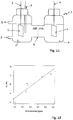
- the figure 2 schematizes another embodiment of an electrochemical device according to the invention.
- the electrochemical device 21 is a dual compartment electrolyser comprising a bioanode 22 and a biocathode 35 formed of graphite granules 20 connected to the external electrical circuit by graphite rods.
- the anode 28 and cathode compartments 39 are separated by a cation exchange membrane 24 (ECM).
- ECM cation exchange membrane 24
- the anode compartment 28 has an inlet 23 and an electrolyte outlet 10A, for example connected to pumping means (not shown).
- the cathode compartment 39 has an inlet 30 and an electrolyte outlet 31 10C that can be connected to pumping means (not shown) independent of the pumping means connected to the anode compartment.
- This device makes it possible to independently modulate the level 26 of electrolyte 10 in the anode compartment and the level 36 of electrolyte 10C in the cathode compartment, thus the volume of electrolyte in each of the compartments and thus to adjust the ratio of the active surfaces (that is to say, immersed) of the two bioelectrodes.
- this modulation makes it possible to vary the potential difference (E) between the two bioelectrodes. This allows, at first, when starting the system, to have anode potential compatible with the establishment of an electroactive biological activity. In a second step, this makes it possible to control the biosynthesis reactions at the cathode regulating its potential.
- the electrochemical device 21 is a double compartment electrolyser such as that presented in FIG. figure 2 comprising a bioanode 22 and a biocathode 35 formed of graphite granules connected to the external electrical circuit by graphite rods.
- the anode 28 and cathode compartments 39 are separated by a cation exchange membrane 24 (ECM).
- ECM cation exchange membrane 24
- the anode compartment 28 has an inlet 23 and an electrolyte outlet 10A, for example connected to pumping means (not shown).
- the cathode compartment 39 has an inlet 30 and an electrolyte outlet 31 10C that can be connected to pumping means (not shown) independent of the pumping means connected to the anode compartment.
- the embodiment of the method of the present invention is here to modulate the potential difference between the anode 22 and the cathode 35 through the use of a potentiostat to control the intensity.
- the maximum intensities obtained reach values of 5, 13 and 20 mA respectively for applied potential differences of 0.5, 1 and 1.5 V, confirming the increase in the intensity measured as a function of the increase in potential difference applied between the bioanode and the granular biocathode.
- the control of the potential difference between bioanode and biocathode thus makes it possible to regulate the intensity of the current in the double compartment bioelectrochemical reactor comprising electrodes formed of graphite granules and consequently the activity of the biocathode.
- the electrochemical device is a double compartment electrolyser comprising a bioanode and a biocathode and a system for supplying and withdrawing the liquid phase.
- the anode compartment has an input E and an electrolyte output S, connected to pumping means (not shown) for a continuous supply of the electrolyte in this compartment.
- the anode compartment of a reactor was fed continuously with bio-waste (from the substrate composition shown in Table 1 of Example 4) by means of a pump making it possible to regulate the inflow and outflow.
- a surge system to maintain a constant liquid level within the anode compartment maintained at a volume of 1 L.
- the impact of different substrate concentrations in the feed (COD load: chemical oxygen demand) on the intensity was tested for an average flow rate of 82 mL / day over an average duration of 10 days. The results are presented on the figure 12 .
Landscapes
- Chemical & Material Sciences (AREA)
- Engineering & Computer Science (AREA)
- Organic Chemistry (AREA)
- Chemical Kinetics & Catalysis (AREA)
- Electrochemistry (AREA)
- Materials Engineering (AREA)
- Metallurgy (AREA)
- Life Sciences & Earth Sciences (AREA)
- Analytical Chemistry (AREA)
- Biochemistry (AREA)
- Health & Medical Sciences (AREA)
- Wood Science & Technology (AREA)
- Bioinformatics & Cheminformatics (AREA)
- Zoology (AREA)
- Microbiology (AREA)
- Sustainable Development (AREA)
- Automation & Control Theory (AREA)
- Inorganic Chemistry (AREA)
- Biomedical Technology (AREA)
- Biotechnology (AREA)
- Computer Hardware Design (AREA)
- General Engineering & Computer Science (AREA)
- General Health & Medical Sciences (AREA)
- Genetics & Genomics (AREA)
- Manufacturing & Machinery (AREA)
- Sustainable Energy (AREA)
- General Chemical & Material Sciences (AREA)
- Electrolytic Production Of Non-Metals, Compounds, Apparatuses Therefor (AREA)
- Apparatus Associated With Microorganisms And Enzymes (AREA)
- Micro-Organisms Or Cultivation Processes Thereof (AREA)
Description
- La présente invention concerne le domaine électrochimique, et plus particulièrement les procédés électrochimiques mettant en oeuvre des dispositifs bioélectrochimiques c'est-à-dire des dispositifs électrochimiques dont l'une au moins des électrodes est au contact de microorganismes.
- Les dispositifs bioélectrochimiques sont récents. L'étude des anodes biologiques dans le cadre des biopiles a débuté au cours des années 2000 dans des dispositifs expérimentaux pour lesquels la cathode était le plus souvent abiotique. Parfois, des cathodes à air qui pouvaient éventuellement être biologiques ont toutefois été utilisées.
- Les dispositifs bioélectrochimiques font l'objet d'une attention accrue ces dernières années en vue d'étudier la valorisation et la bioconversion de la matière organique notamment issue de déchets organiques dans des électrolyseurs microbiens. Ces dispositifs bioélectrochimiques nécessitent le couplage d'une anode biologique (appelée aussi bioanode) à une cathode biologique (appelée aussi biocathode) et requièrent une bonne coordination cinétique des activités biologiques à l'anode et à la cathode. Souvent, ces activités ne sont pas bien synchronisées. Ainsi, l'activité de l'une des bioélectrodes prend en général le pas et peut entraîner, dans le circuit, des potentiels ou des courants néfastes au bon fonctionnement de l'autre bioélectrode.
- Jusqu'à présent l'étude des biocathodes pour l'électrosynthèse n'a pratiquement jamais été réalisée dans un système comportant également une bioanode. Pourtant, pour les futures applications industrielles de bioraffinage des déchets, l'utilisation conjointe d'une bioanode et d'une biocathode est nécessaire.
- Un premier but de l'invention est donc de palier les inconvénients des procédés existants en proposant de réguler les variations d'activités respectives des bioélectrodes, c'est-à-dire la coordination des activités microbiennes à la fois sur la bioanode et sur la biocathode d'un dispositif électrochimique dont les compartiments anodique et cathodique renferment des microorganismes.
- A cet effet la présente invention propose un procédé de régulation de l'activité d'un dispositif électrochimique comportant une anode et une cathode plongées dans un électrolyte respectivement placé dans un compartiment anodique et un compartiment cathodique séparés par au moins une membrane ou reliés l'un à l'autre par un pont salin, le dispositif comportant éventuellement une électrode de référence, une différence de potentiel étant appliquée entre l'anode et la cathode, ou entre l'anode et l'électrode de référence, caractérisé en ce que l'électrolyte du compartiment anodique, ainsi que l'électrolyte du compartiment cathodique, contiennent des microorganismes en suspension ou sous forme de biofilm(s), les électrodes étant respectivement dénommées bioanode et biocathode, et en ce que le fonctionnement du dispositif est régi par une double régulation :
- une première régulation, dite régulation prioritaire, de la différence de potentiel entre la bioanode et la biocathode, ou entre la bioanode et l'électrode de référence, entre une valeur limite minimale permettant le développement d'un biofilm électroactif à la bioanode et une valeur limite maximale inférieure au potentiel d'oxydation dudit biofilm, et
- une seconde régulation, dite régulation secondaire, lorsque la première régulation est mise en place, optimisant le rendement faradique de la biocathode.
- Classiquement, dans les expériences d'électrosynthèse microbienne, les réactions de réduction ayant lieu sur les biocathodes, les dispositifs électrochimiques de l'art antérieur s'appuient sur une simple régulation du courant ou du potentiel à la cathode. Lorsqu'on est en présence d'une bioanode, ce type de régulation peut entraîner une augmentation forte du potentiel à l'anode qui conduit à l'inactivation de la biomasse électroactive par une oxydation trop importante au contact de cette électrode.
- Or, de façon surprenante et inattendue, les inventeurs ont constaté qu'il est préférable d'employer, au démarrage, une stratégie de régulation du potentiel à l'anode. Une fois que l'activité microbienne d'oxydation à l'anode permet d'atteindre un niveau de courant dans le circuit jugé suffisant, il devient nécessaire de réguler la densité de courant et/ou le potentiel à la biocathode pour permettre une activité biologique adéquate à la cathode (régulation du courant ou du potentiel sur les plages compatibles avec l'activité de l'anode). Le procédé selon l'invention prend donc en compte en premier lieu l'évolution de l'activité biologique à l'anode, par la régulation prioritaire du potentiel à la bioanode (loi prioritaire).
- Dans l'ensemble du texte, les expressions efficacité coulombique, rendement coulombique, efficacité faradique et rendement faradique sont équivalentes et ont la même signification sur le plan électrochimique.
- La densité de courant (en A/m2) à la bioanode ou à la biocathode correspond à l'intensité par unité de surface de l'électrode dont il est question.
- Par "bioanode" et "biocathode", on entend, ici, des électrodes plongées dans un électrolyte au contact de microorganismes et d'un électrolyte. Ces microorganismes peuvent s'organiser en biofilms directement au contact des électrodes, des parois du réacteur et/ou être en suspension dans l'électrolyte. Dans l'ensemble du texte on utilisera indifféremment les termes d'anode ou de bioanode, et de cathode ou de biocathode.
- De manière avantageuse, tout en maintenant la régulation du potentiel à la bioanode, l'optimisation de l'activité de la biocathode en vue de la production d'espèces chimiques particulières est asservie à des paramètres physico-chimiques mesurés au niveau du compartiment cathodique, telles que la concentration d'une ou plusieurs espèces chimiques dans l'électrolyte ou dans ciel gazeux environnant la biocathode, ou au débit de production de gaz à la biocathode.
- L'espèce chimique mesurée au niveau du compartiment cathodique, est par exemple le dihydrogène (résultant d'un phénomène abiotique d'électrolyse de l'eau et signifiant que l'intensité doit être réduite pour améliorer le fonctionnement de la biocathode) ou le méthane (qui signe le développement d'une électro-méthanogenèse à la biocathode).
- Selon un mode de réalisation avantageux de l'invention, tout en maintenant la première régulation de différence de potentiel gérant l'activité biologique au niveau de la bioanode, la seconde régulation régit l'optimisation de la densité de courant à la biocathode en vue de la production d'espèces chimiques particulières au niveau de la biocathode.
- Cette optimisation de densité de courant à la biocathode peut être réalisée :
- selon une première variante : par le biais d'un dispositif électronique permettant de fixer directement l'intensité à la biocathode, et/ou par le biais d'un générateur de tension ou d'un potentiostat, permettant de faire varier, de préférence avec une précision de quelques millivolts, le potentiel de la bioanode, de la biocathode et/ou la différence de potentiel entre bioanode et biocathode, ou
- selon une seconde variante : par des variations du rapport de la surface active de la bioanode à la surface active de la biocathode.
- Dans cette seconde variante, les variations du rapport de la surface active de la bioanode à la surface active de la biocathode peuvent être réalisées :
- soit par des variations de la surface immergée de la bioanode et/ou de la biocathode, ces variations de la surface immergée de la bioanode et/ou de la biocathode pouvant être obtenues par des variations du niveau de l'électrolyte dans le compartiment anodique et/ou dans le compartiment cathodique, ou encore obtenues par des déplacements de la bioanode et/ou de la biocathode dans l'électrolyte ;
- soit par la modification du nombre de bioanodes dans le compartiment anodique et/ou la modification du nombre de biocathodes dans le compartiment cathodique : c'est-à-dire l'introduction d'une ou plusieurs nouvelles bioanodes (respectivement biocathodes) dans le compartiment anodique (respectivement cathodique), ou le retrait d'une ou plusieurs bioanodes et/ou biocathodes, pour le cas où ce(s) compartiment(s) en comprend(nent) déjà plusieurs.
- Dans les cas où les compartiments anodique et cathodique comprennent plusieurs électrodes (respectivement bioanodes ou biocathodes), ces électrodes sont bien entendues toutes connectées au même circuit électrique du dispositif électrochimique.
- Selon un autre mode de réalisation, l'activité de la biocathode peut être régulée par des paramètres physico-chimiques au niveau du compartiment anodique. Plus particulièrement, tout en maintenant la régulation du potentiel à la bioanode, l'optimisation de l'activité de la biocathode en vue de la production d'espèces chimiques particulières est alors réalisée par la régulation de paramètres chimiques au niveau du compartiment anodique, telles que la concentration d'une ou plusieurs espèces chimiques dans l'électrolyte ou dans ciel gazeux environnant la bioanode.
- Cette espèce chimique est avantageusement une molécule non fermentescible, telle qu'un acide organique ou son sel, de préférence choisi parmi l'acétate, le lactate ou le propionate.
- A titre d'exemple de régulation prioritaire, lorsque la bioanode, telle qu'une électrode en carbone, est plongée dans un électrolyte aqueux à pH d'environ 7 la valeur maximale de la différence de potentiel entre la bioanode et une électrode normale à hydrogène, dite électrode de référence, est telle que le potentiel de la bioanode est inférieur ou égal à 1 V par rapport à ladite électrode de référence, de préférence inférieur à 0,5 V par rapport à ladite électrode de référence, de manière à éviter l'électrolyse de l'eau.
- La présente invention concerne également le dispositif électrochimique pour la réalisation du procédé décrit ci-dessus, permettant l'adaptation des courants et/ou potentiels à la cathode en fonction de l'évolution de l'activité biologique à l'anode.
- Plus particulièrement le dispositif électrochimique selon l'invention comprenant :
- une anode et une cathode plongées dans un électrolyte respectivement placé dans un compartiment anodique et un compartiment cathodique séparés par au moins une membrane ou reliés l'un à l'autre par un pont salin, l'électrolyte du compartiment anodique contenant des microorganismes, ainsi que l'électrolyte du compartiment cathodique, les électrodes étant respectivement dénommées bioanode et biocathode,
- éventuellement une électrode de référence,
- des moyens permettant d'appliquer une différence de potentiel entre la bioanode et la biocathode, ou entre la bioanode et l'électrode de référence, et des moyens de régulation de cette différence de potentiel,
- La membrane peut être une membrane échangeuse d'ions : échangeuse de cations, échangeuse d'anions, échangeuse de protons, ou en variante être une membrane d'osmose.
- Selon l'invention ce dispositif électrochimique comprend également des capteurs ou sondes disposés dans l'électrolyte et/ou dans le ciel gazeux environnant respectivement la bioanode ou la biocathode, lesdits capteurs ou sondes mesurant des paramètres physico-chimiques au niveau du compartiment anodique et/ou du compartiment cathodique, telles que la concentration d'une ou plusieurs espèces chimiques.
- Le dispositif électrochimique selon l'invention peut également comprendre des moyens permettant de faire varier le niveau de l'électrolyte dans au moins un des compartiments (par exemple au moyen d'une pompe connectée à une entrée et une sortie du compartiment correspondant) et/ou permettant le déplacement de la bioanode et/ou de la biocathode dans l'électrolyte.
- L'invention sera bien comprise à la lecture de la description suivante d'exemples de réalisation, en référence aux dessins annexés dans lesquels :
- La
figure 1 est un schéma en coupe d'un mode de réalisation d'un dispositif électrochimique selon l'invention ; - La
figure 2 est un schéma en coupe d'un autre mode de réalisation d'un dispositif électrochimique selon l'invention; - La
figure 3 montre les courbes de densité de courant (figure 3A ) et de potentiel (figure 3B ) de l'exemple 1 ; - La
figure 4 schématise, pour l'exemple 1, le bilan des électrons au niveau de la biocathode de l'exemple 1 avec les quantités cumulées d'acides gras volatils (AGVs), de méthane (CH4) et de dihydrogène (H2) (figure 4A ) et les acides gras volatils mesurées au niveau du compartiment cathodique ; - La
figure 5 montre l'intensité dans le dispositif électrochimique selon l'exemple 2 en fonction du temps ; - La
figure 6 montre l'intensité dans le dispositif électrochimique selon l'exemple 3 en fonction du temps, et les déplacements de la bioanode dans l'électrolyte ; - La
figure 7 montre l'intensité dans deux dispositifs électrochimiques selon l'exemple 4 en fonction du temps ; - La
figure 8 montre le potentiel dans deux dispositifs électrochimiques selon l'exemple 4 en fonction du temps ; - La
figure 9 est un schéma général d'un dispositif électrochimique selon l'invention comportant différents capteurs physico-chimiques ; - La
figure 10 montre des courbes de variation d'intensité au cours du temps dans trois dispositifs selon l'invention fonctionnant à des différences de potentiel variées entre l'anode et la cathode ; - La
figure 11 est un schéma général d'une variante de dispositif électrochimique selon l'invention comportant une alimentation en continu de l'électrolyte dans le compartiment anodique ; - La
figure 12 montre la corrélation entre l'intensité du courant dans le circuit du dispositif de lafigure 11 et la charge journalière en DCO (demande chimique en oxygène) dans l'alimentation en électrolyte du compartiment anodique. - Le dispositif électrochimique 1, présenté à la
figure 1 , est un électrolyseur à double compartiment comportant une bioanode 3 et une biocathode 6. Les deux compartiments anodique 8 et cathodique 9 sont constitués de récipients en verre de 1,5 L de volume total séparés par une membrane 4 échangeuse de cations (MEC, Fumasep® FKE, Germany). L'électrolyte 10A, 10C utilisé correspond au milieu Biochemical Methane Potential (BMP) (selon la norme NF EN ISO 11734) tamponné avec 8 g/l de carbonates. Le substrat utilisé est l'acide acétique à 600 mg/l. Le matériau de base de la bioanode est un morceau de 4 cm ∗ 4 cm de tissu de carbone (Paxitech®, France) il est connecté au circuit électrique par un fil de platine 2. Le matériau de la biocathode est une plaque d'acier inoxydable (Outokumpu®, 254 SMO) de 4 cm ∗ 4 cm connectée au circuit électrique par une tige d'acier 5. - La bioanode a été "pré-cultivée" sur acide acétique dans des boues biologiques ce qui a permis d'obtenir à sa surface un biofilm contenant des bactéries électroactives sur le tissu de carbone. Le compartiment cathodique 9 peut recevoir ou non l'inoculation d'une culture de bactéries acétogènes préparée à partir d'un consortium microbien de traitement anaérobie de déchets (biocathode).
- L'anode 3 est, dans un premier temps, polarisée à +0,158 V par rapport à une électrode de référence 7 au calomel saturé (notée SCE pour Saturated Calomel Electrode) au moyen d'un potentiostat (BioLogic®, France, VMP3, logiciel EC-Lab) (loi prioritaire). Lorsque la densité de courant atteint 5 A/m2, le potentiostat est programmé pour limiter la densité de courant à cette valeur. Ceci permet de réguler l'activité de la cathode (loi secondaire). Enfin si le potentiel à l'anode dépasse +0,2V versus SCE, le potentiostat est alors réglé pour rebasculer en contrôle potentiel et le maintenir à cette valeur pour préserver l'activité biologique de la bioanode (loi prioritaire). Cette régulation est illustrée par la
figure 3 sur les 16 premiers jours de l'expérience. - La
figure 3 montre les courbes de la densité de courant (figure 3A ) et du potentiel de la bioanode mesuré par rapport à l'électrode de référence 7 au calomel saturé (figure 3B ) au cours des 16 premiers jours de l'expérience. En début d'expérience le courant augmente rapidement avec le développement du biofilm électroactif à l'anode. Le courant est ensuite régulé à 5 A/m2 pour optimiser le rendement de production d'acides gras volatils (AGVs) à la cathode (loi secondaire). Dans la dernière phase le courant décroit avec l'épuisement du substrat pendant que la loi prioritaire impose à nouveau le potentiel à l'anode 3. - Tout au long de l'expérience sont prélevés des échantillons dans lesquels sont mesurées les concentrations en acides gras volatils et en lactate par chromatographie ionique (DIONEX DX 120, colonne IONPAC® ICE-AS1 (9x250 mm)). Les éluants utilisés sont l'acide heptafluorobutyrique (0,4 mmol/l) et l'hydroxyde de tetrabutylammonium (TBAOH, 5 mmol/l). Les concentrations en formiate, acétate, lactate, propionate, butyrate et valérate sont ainsi mesurées dans une gamme allant de 10 mg/l à 500 mg/l. Les compositions des ciels gazeux des compartiments anodiques et cathodiques sont mesurées par chromatographie en phase gazeuse (Varian CP 4900). Les trois colonnes de l'instrument permettent de mesurer les proportions des gaz suivants : O2, N2, CH4, CO2, H2, H2S et NO2.
- L'expérience a été menée pendant 30 jours, avec deux injections de substrat dans le compartiment anodique 8 (600 mg/l d'acide acétique) aux jours 0 et 15. Trois pilotes ont été lancés en parallèle dans les mêmes conditions avec inoculation à la cathode (biocathode) et trois autres pilotes témoins ont été lancés sans inoculation à la cathode. Les comportements des trois pilotes avec inoculation se sont révélés très similaires tout au long de l'expérience, l'un d'eux a été arrêté au jour 15 pour permettre l'observation des électrodes par microscopie. Le bilan de la production de la biocathode de l'un de ces pilotes est présenté à la
figure 4 (parties A et B). - La
figure 4A montre le bilan des électrons pour une biocathode 6 avec inoculation. La courbe supérieure indique la quantité d'électrons arrivant à la biocathode. Les quantités cumulées d'acides gras volatils (AGVs), de méthane (CH4) et d'hydrogène (H2), mesurées en équivalents électrons, sont indiquées par les surfaces hachurées. Lafigure 4B montre le détail des concentrations en acides gras volatils mesurées dans le compartiment cathodique 9. Le formiate et l'acétate sont les principaux acides produits. Les concentrations mesurées pour les autres acides (lactate, propionate, butyrate et valérate) sont nulles et ne sont donc pas représentées sur cette figure. - Durant la première phase de l'expérience (jours 1 à 15), l'hydrogène (H2) et le méthane (CH4) sont principalement produits au niveau des compartiments cathodiques ayant reçu une inoculation tandis que les pilotes sans inoculation dans le compartiment cathodique produisent uniquement de l'hydrogène. Le rendement faradique à la biocathode est alors de 60% avec 53% des électrons utilisés pour produire du méthane (
figure 4A ). - Au jour 15, la deuxième injection de substrat est réalisée dans le compartiment anodique 8 et 10 mmol/l de 2-bromo-éthane sulfonate (BES) sont injectés dans le compartiment cathodique 9 pour inhiber la méthanogenèse. Durant la seconde phase, les acides gras volatils tels que le formiate et l'acétate sont principalement produits, ainsi que de faibles quantités d'hydrogène et de méthane. Le rendement faradique à la cathode atteint alors 80%. 29% des électrons ont été utilisés pour produire l'acétate. Le taux maximum de production d'acétate enregistré pendant cette phase est de 11 g d'acétate/m2/jour. Par ailleurs 18%, 19% et 13% des électrons sont utilisés pour la production de formiate, d'hydrogène et de méthane respectivement (
figure 4 ). Des traces de caprylate ont également été détectées par des analyses de chromatographie en phase gazeuse couplée à un spectromètre de masse. - Le rendement faradique à l'anode pendant l'expérience est de 85% en moyenne.
- Les observations des bioanodes et biocathodes en microscopie confocale laser à balayage à 15 jours et à 30 jours révèlent une importante colonisation microbienne des deux bioélectrodes.
- Optimisation de l'intensité à la biocathode par la régulation de la différence de potentiel.
- Dans cet exemple de réalisation, le réacteur bioélectrochimique est un électrolyseur à double compartiment comme celui présenté à la
figure 1 et opéré sous les mêmes conditions expérimentales que l'exemple 1. Le mode de réalisation du procédé de la présente invention consiste ici à moduler la différence de potentiel entre l'anode 3 et la cathode 6 grâce à l'utilisation d'un potentiostat afin de contrôler l'intensité à la biocathode. Lafigure 5 présente un exemple d'intensité débitée dans le réacteur bioélectrochimique au cours du temps. Les deux différents niveaux d'intensité observés (jours 0-1 et 3-6 d'une part, jours 1-3 d'autre part) correspondent à deux différences de potentiel imposées entre la bioanode et la biocathode. La différence de potentiel imposée a été soit 0,9 V (jours 0-1 et 3-6) soit 1,4 V (jours 1-3). - Plus particulièrement, dans la première phase de l'expérience, la différence de potentiel est établie à 0,9 V entre la bioanode et la biocathode. Après environ un jour d'expérience, la différence de potentiel est augmentée à 1,4 V entre les deux électrodes. La courbe d'intensité en fonction du temps obtenue confirme une augmentation de l'intensité due à cette variation de la différence de potentiel, passant d'environ 5-6 mA à 15 mA. Après 4 jours, la différence de potentiel est rétablie à 0,9 V et est corrélée avec un retour de l'intensité à une valeur très proche de sa valeur initiale (environ 5 mA). Le contrôle de la différence de potentiel entre bioanode et biocathode permet donc de réguler l'intensité du courant au sein du réacteur bioélectrochimique et par conséquent l'activité de la biocathode.
- Optimisation de l'intensité à la biocathode par déplacement de la bioanode dans l'électrolyte.
- Dans cet exemple de réalisation, le réacteur bioélectrochimique est un électrolyseur à double compartiment comme celui présenté à la
figure 1 et opéré sous les mêmes conditions expérimentales que l'exemple 1. L'invention consiste ici à moduler la surface de bioanode immergée dans l'électrolyte afin de faire varier l'intensité à la biocathode. Lafigure 6 présente un exemple d'intensité débitée dans le réacteur bioélectrochimique au cours du temps. Les déplacements de la bioanode dans le compartiment sont indiqués par les flèches. Au départ, la bioanode 3 est complètement immergée dans l'électrolyte 10A. Les flèches vers le haut indiquent que la moitié de l'électrode passe en position émergée, les flèches vers le bas indiquent que l'électrode est à nouveau immergée en totalité. On constate que les variations brusques d'intensité correspondent bien à des variations de la surface immergée de la bioanode. - En effet, dans cet exemple de réalisation, la surface immergée de la bioanode est modifiée plusieurs fois pendant l'expérience. Après un peu plus de 1 jour, la moitié de la bioanode 3 est sortie de l'électrolyte réduisant la surface immergée de moitié. On observe parallèlement à cela une baisse de l'intensité de 8 mA à 5 mA environ. Au deuxième jour, la bioanode est replongée totalement dans l'électrolyte et on note alors une hausse brutale de l'intensité. L'expérience est ainsi répétée 3 fois et permet d'observer à chaque variation de la surface immergée de la bioanode une variation corrélée de l'intensité à la biocathode. Le contrôle de la surface immergée de la bioanode permet donc de réguler l'intensité du réacteur bioélectrochimique et par conséquent l'activité de la biocathode.
- Régulation de l'intensité à la biocathode en fonction de la concentration en DCO (Demande chimique en Oxygène) à l'anode.
- Dans cet exemple de réalisation, le réacteur bioélectrochimique est un électrolyseur à double compartiment comme celui présenté en détail à la
figure 1 et opéré sous les mêmes conditions expérimentales que l'exemple 1 à l'exception de la nature du substrat apporté à l'anode. En effet dans cette réalisation, les compartiments anodiques de deux réacteurs ont été alimentés en biodéchets, un substrat complexe de 63 g/l de DCO totale, dont la composition en acides gras volatils et en acide lactique est présentée dans le tableau 1 ci-dessous.Tableau 1 Conc. (g/l) Acide lactique 10,52 Acide formique 0,00 Acide acétique 0,38 Acide propionique 1,28 Acide butyrique 5,32 Acide valérique 0,00 - La
figure 7 présente les courbes d'intensité en fonction du temps obtenues. La courbe en pointillés correspond au réacteur dont le compartiment anodique 8 a reçu 1 ml de substrat aux jours 0, 4, 5, 7, 8 et 11. La courbe pleine correspond au réacteur dont le compartiment anodique 8 a reçu 3 ml de substrat aux jours 0, 4, 5, 7, 8 et 11. - Le réacteur le moins alimenté a reçu 31,5 mg/j/l de DCO en moyenne et le second 94,5 mg/j/l de DCO en moyenne. Cette différence de concentration en substrat a permis d'obtenir une intensité différente pour chaque réacteur puisque l'intensité moyenne obtenue pour le réacteur alimenté avec 1 ml de substrat a été de 1,1 mA, tandis que l'intensité moyenne obtenue pour le réacteur alimenté avec 3 ml de substrat a été de 4,3 mA (
Figure 7 ). La régulation de la concentration en substrat à la bioanode permet donc de réguler l'intensité du réacteur bioélectrochimique et par conséquent de réguler l'activité de la biocathode comme illustré par les potentiels mesurés aux biocathodes : voir lafigure 8 qui montre les potentiels des biocathodes des deux réacteurs bioélectrochimiques au cours du temps. Ces potentiels sont mesurés par rapport à des électrodes de référence au calomel saturé (SCE). La courbe en pointillés correspond au réacteur qui a été alimenté avec 1 ml de substrat aux jours 0, 4, 5, 7, 8 et 11. La courbe pleine correspond au réacteur qui a été alimenté avec 3 ml de substrat aux jours 0, 4, 5, 7, 8 et 11. - Optimisation de l'activité de la biocathode par régulation de paramètres chimiques.
- Cet exemple met en oeuvre un dispositif électrochimique comportant des capteurs physico-chimiques. Ce dispositif électrochimique 11 schématisé à la
figure 9 comporte une anode 3 et une cathode 6 reliées à un dispositif électronique 17 comprenant un potentiostat. Une membrane 14, par exemple échangeuse de cations, sépare le compartiment anodique 8 du compartiment cathodique 9 renfermant l'électrolyte 10A, 10C. - Différents capteurs ou sondes peuvent être intégrés aux deux compartiments afin de suivre l'évolution des paramètres physico-chimiques du système : par exemple, un capteur de gaz 13 disposé dans le ciel gazeux 12 du compartiment anodique et une sonde 18 plongeant dans l'électrolyte 10A liquide du compartiment anodique 8. De même, un capteur 16 de gaz est relié au ciel gazeux 15 du compartiment cathodique et une sonde 19 plonge dans l'électrolyte 10C du compartiment cathodique 9.
- Tout en maintenant la régulation du potentiel à la bioanode, l'optimisation de l'activité de la biocathode est réalisée par la régulation de paramètres chimiques au niveau du compartiment anodique 8, telles que la concentration d'une ou plusieurs espèces chimiques dans l'électrolyte 10A ou dans le ciel gazeux 12 environnant la bioanode, le pH, etc... La présence de différents capteurs/sondes intégrés aux deux compartiments permet de suivre en direct l'évolution des paramètres physicochimiques du système. Selon la valeur de ces paramètres, le dispositif électronique 17 peut ensuite optimiser le fonctionnement de la biocathode en jouant sur l'intensité du système, le potentiel électrique, etc...
- La
figure 2 schématise un autre mode de réalisation d'un dispositif électrochimique selon l'invention. - Dans cet exemple de réalisation, le dispositif électrochimique 21 est un électrolyseur à double compartiment comportant une bioanode 22 et une biocathode 35 formées de granules de graphite 20 connectées au circuit électrique extérieur par des tiges de graphite. Les compartiments anodique 28 et cathodique 39 sont séparés par une membrane 24 échangeuse de cations (MEC). Le compartiment anodique 28 comporte une entrée 23 et une sortie 25 d'électrolyte 10A, par exemple reliées à des moyens de pompage (non représentés). De même, le compartiment cathodique 39 comporte une entrée 30 et une sortie 31 d'électrolyte 10C pouvant être reliées à des moyens de pompage (non représentés) indépendants des moyens de pompage reliés au compartiment anodique.
- Ce dispositif permet de moduler indépendamment le niveau 26 d'électrolyte 10 dans le compartiment anodique et le niveau 36 d'électrolyte 10C dans le compartiment cathodique, donc le volume d'électrolyte dans chacun des compartiments et ainsi à adapter le rapport des surfaces actives (c'est-à-dire immergées) des deux bioélectrodes.
- Dans le cas où l'on impose le courant (I), cette modulation permet de faire varier la différence de potentiel (E) entre les deux bioélectrodes. Cela permet, dans un premier temps, lors du démarrage du système, d'avoir un potentiel à l'anode compatible avec l'établissement d'une activité biologique électroactive. Dans un second temps, cela permet de contrôler les réactions de biosynthèse à la cathode régulant son potentiel.
- Dans le cas où l'on impose la différence de potentiel (E) entre les deux bioélectrodes, ce système de régulation permet de moduler le courant électrique (I), ce qui va influer directement sur les efficacités carboniques de production des différentes molécules, permettant d'optimiser les rendements de conversion des électrons en molécules d'intérêt.
- Optimisation de l'intensité par la régulation de la différence de potentiel (ΔE) dans un électrolyseur à double compartiment comportant des électrodes formées de granules de graphite.
- Dans cet exemple de réalisation, le dispositif électrochimique 21 est un électrolyseur à double compartiment tel que celui présenté à la
figure 2 comportant une bioanode 22 et une biocathode 35 formées de granules de graphite 20 connectées au circuit électrique extérieur par des tiges de graphite. Les compartiments anodique 28 et cathodique 39 sont séparés par une membrane 24 échangeuse de cations (MEC). Le compartiment anodique 28 comporte une entrée 23 et une sortie 25 d'électrolyte 10A, par exemple reliées à des moyens de pompage (non représentés). De même, le compartiment cathodique 39 comporte une entrée 30 et une sortie 31 d'électrolyte 10C pouvant être reliées à des moyens de pompage (non représentés) indépendants des moyens de pompage reliés au compartiment anodique. - Le mode de réalisation du procédé de la présente invention consiste ici à moduler la différence de potentiel entre l'anode 22 et la cathode 35 grâce à l'utilisation d'un potentiostat afin de contrôler l'intensité. La
figure 10 présente un exemple d'intensité débitée au cours du temps dans trois réacteurs bioélectrochimiques opérés dans les mêmes conditions pour trois différences de potentiel appliquées : 0,5 V (courbe en pointillés), 1 V (courbe en tirets) et 1,5 V (ligne continue). Au temps t=0 jour, le substrat (acétate à une concentration finale de 600 mg/l) est ajouté et l'intensité augmente pour les trois réacteurs. Les intensités maximales obtenues atteignent respectivement des valeurs de 5, 13 et 20 mA pour les différences de potentiel appliquées de 0,5, 1 et 1,5 V, confirmant l'augmentation de l'intensité mesurée en fonction de l'augmentation de la différence de potentiel appliquée entre la bioanode et la biocathode granulaire.
Le contrôle de la différence de potentiel entre bioanode et biocathode permet donc de réguler l'intensité du courant au sein du réacteur bioélectrochimique à double compartiment comportant des électrodes formées de granules de graphite et par conséquent l'activité de la biocathode. - Dans cet exemple de réalisation, le dispositif électrochimique, schématisé à la
figure 11 , est un électrolyseur à double compartiment comportant une bioanode et une biocathode et un système d'alimentation et de soutirage de la phase liquide. Plus particulièrement, dans cet exemple, le compartiment anodique comporte une entrée E et une sortie S d'électrolyte, reliées à des moyens de pompage (non représentés) permettant une alimentation en continu de l'électrolyte dans ce compartiment. - Suivant ce mode de réalisation, le compartiment anodique d'un réacteur a été alimenté en continu en biodéchets (à partir de la composition en substrat présentée dans le tableau 1 de l'exemple 4) grâce à une pompe permettant de régler le débit entrant et à un système se surverse permettant de conserver un niveau de liquide constant au sein du compartiment anodique maintenu à un volume de 1 L.
L'impact de différentes concentrations de substrat dans l'alimentation (charge DCO : demande chimique en oxygène) sur l'intensité a été testé pour un débit moyen de 82 mL/jour sur une durée moyenne de 10 jours. Les résultats sont présentés sur lafigure 12 . - La corrélation constatée entre l'intensité du courant dans le circuit et le débit de DCO alimenté montre bien que la régulation du débit d'alimentation en substrat permet de réguler l'intensité du courant.
Claims (18)
- Procédé de régulation de l'activité d'un dispositif électrochimique (1) comportant une anode (3) et une cathode (6) plongées dans un électrolyte respectivement placé dans un compartiment anodique (8) et un compartiment cathodique (9) séparés par au moins une membrane (4) ou reliés l'un à l'autre par un pont salin, le dispositif comportant éventuellement une électrode de référence (7), une différence de potentiel étant appliquée entre l'anode et la cathode, ou entre l'anode et l'électrode de référence,
caractérisé en ce que l'électrolyte (10A) du compartiment anodique, ainsi que l'électrolyte (10C) du compartiment cathodique, contiennent des microorganismes en suspension ou sous forme de biofilm(s), les électrodes étant respectivement dénommées bioanode et biocathode, et en ce que le fonctionnement du dispositif est régi par une double régulation :- une première régulation, dite régulation prioritaire, de la différence de potentiel entre la bioanode et la biocathode, ou entre la bioanode et l'électrode de référence, entre une valeur limite minimale permettant le développement d'un biofilm électroactif à la bioanode et une valeur limite maximale inférieure au potentiel d'oxydation dudit biofilm, et- une seconde régulation, dite régulation secondaire, lorsque la première régulation est mise en place, optimisant le rendement faradique de la biocathode. - Procédé selon la revendication 1,
caractérisé en ce que, tout en maintenant la régulation du potentiel à la bioanode, l'optimisation de l'activité de la biocathode en vue de la production d'espèces chimiques particulières est asservie à des paramètres physico- chimiques mesurés au niveau du compartiment cathodique (9), telles que la concentration d'une ou plusieurs espèces chimiques dans l'électrolyte ou dans ciel gazeux environnant la biocathode, ou au débit de production de gaz à la biocathode. - Procédé selon la revendication 1 ou 2,
caractérisé en ce que, tout en maintenant la première régulation de différence de potentiel gérant l'activité biologique au niveau de la bioanode, la seconde régulation régit l'optimisation de la densité de courant à la biocathode en vue de la production d'espèces chimiques particulières au niveau de la biocathode. - Procédé selon la revendication 3,
caractérisé en ce que l'optimisation de la densité de courant à la biocathode est réalisée par le biais d'un dispositif électronique permettant de fixer directement densité de courant à la biocathode, et/ou par le biais d'un générateur de tension ou d'un potentiostat, permettant de faire varier, de préférence avec une précision de quelques millivolts, le potentiel de la bioanode, de la biocathode et/ou la différence de potentiel entre bioanode et biocathode. - Procédé selon la revendication 3 ou 4,
caractérisé en ce que l'optimisation de la densité de courant à la biocathode est réalisée par des variations du rapport de la surface active de la bioanode à la surface active de la biocathode. - Procédé selon la revendication 5,
caractérisé en ce que les variations du rapport de la surface active de la bioanode à la surface active de la biocathode sont réalisées par des variations de la surface immergée de la bioanode et/ou de la biocathode. - Procédé selon la revendication 6,
caractérisé en ce que les variations de la surface immergée de la bioanode et/ou de la biocathode sont obtenues par des variations du niveau de l'électrolyte dans le compartiment anodique et/ou dans le compartiment cathodique. - Procédé selon la revendication 6 ou 7,
caractérisé en ce que les variations de la surface active de la bioanode et/ou de la biocathode sont obtenues par des déplacements de la bioanode et/ou de la biocathode dans l'électrolyte. - Procédé selon l'une quelconque des revendications 5 à 8,
caractérisé en ce que les variations du rapport de la surface active de la bioanode à la surface active de la biocathode sont réalisées par la modification du nombre de bioanodes dans le compartiment anodique et/ou la modification du nombre de biocathodes dans le compartiment cathodique. - Procédé selon l'une quelconque des revendications précédentes,
caractérisé en ce que, tout en maintenant la régulation du potentiel à la bioanode, l'optimisation de l'activité de la biocathode en vue de la production d'espèces chimiques particulières est réalisée par la régulation de paramètres chimiques au niveau du compartiment anodique, telles que la concentration d'une ou plusieurs espèces chimiques dans l'électrolyte ou dans le ciel gazeux environnant la bioanode. - Procédé selon la revendication 2, caractérisé en ce que l'espèce chimique est le dihydrogène.
- Procédé selon la revendication 2, caractérisé en ce que l'espèce chimique est le méthane.
- Procédé selon la revendication 10, caractérisé en ce que l'espèce chimique est une molécule non fermentescible, telle qu'un acide organique ou son sel, de préférence choisi parmi l'acétate, le lactate ou le propionate.
- Procédé selon l'une quelconque des revendications précédentes, caractérisé en ce que lorsque la bioanode, telle qu'une électrode en carbone, est plongée dans un électrolyte aqueux à pH d'environ 7 la valeur maximale de la différence de potentiel entre la bioanode et une électrode normale à hydrogène, dite électrode de référence, est telle que le potentiel de la bioanode est inférieur ou égal à 1 V par rapport à ladite électrode de référence, de préférence inférieur à 0,5 V par rapport à ladite électrode de référence, de manière à éviter l'électrolyse de l'eau.
- Dispositif électrochimique (1) pour la réalisation du procédé selon l'une quelconque des revendications précédentes, comprenant :- une anode (3) et une cathode (6) plongées dans un électrolyte respectivement placé dans un compartiment anodique (8;28) et un compartiment cathodique (9 ;29) séparés par au moins une membrane (4 ;14 ;24) ou reliés l'un à l'autre par un pont salin, l'électrolyte (10A) du compartiment anodique contenant des microorganismes, ainsi que l'électrolyte (10C) du compartiment cathodique, les électrodes étant respectivement dénommées bioanode et biocathode,caractérisé en ce qu'il comprend des moyens permettant d'optimiser le rendement faradique de la biocathode, les moyens comprenant des capteurs ou sondes disposés dans l'électrolyte (10A, 10C) et/ou dans le ciel gazeux (12, 15) environnant respectivement la bioanode (3) ou la biocathode (6), lesdits capteurs ou sondes mesurant des paramètres physicochimiques au niveau du compartiment anodique (28) et/ou du compartiment cathodique (39), telles que la concentration d'une ou plusieurs espèces chimiques.- éventuellement une électrode de référence (7),- des moyens permettant d'appliquer une différence de potentiel entre la bioanode et la biocathode, ou entre la bioanode et l'électrode de référence,- la bioanode et la biocathode étant reliées à un dispositif électronique de régulation de cette différence de potentiel,
- Dispositif électrochimique selon la revendication 15, caractérisé en ce que les capteurs (13,16) ou sondes (18,19) sont reliés au dispositif électronique (17).
- Dispositif électrochimique selon l'une quelconque des revendications 15 ou 16, caractérisé en ce que les compartiments anodique (28) et cathodique (39) sont séparés par une membrane (24) échangeuse de cations, le compartiment anodique comportant une entrée (23) et une sortie (25) d'électrolyte reliés à des moyens de pompage d'électrolyte, le compartiment cathodique comportant une entrée (30) et une sortie (31) d'électrolyte reliées à des moyens de pompage indépendants des moyens de pompage reliés au compartiment anodique.
- Dispositif électrochimique selon l'une quelconque des revendications 15 à 17, caractérisé en ce qu'il comprend des moyens de déplacement de la bioanode (3) et/ou de la biocathode (6) dans l'électrolyte, permettant de faire varier la surface immergée de la bioanode et/ou de la biocathode.
Applications Claiming Priority (2)
| Application Number | Priority Date | Filing Date | Title |
|---|---|---|---|
| FR1459281A FR3026413B1 (fr) | 2014-09-30 | 2014-09-30 | Procede et dispositif de regulation de l'activite d'un systeme bioelectrochimique comportant a la fois une bioanode et une biocathode |
| PCT/FR2015/052585 WO2016051064A1 (fr) | 2014-09-30 | 2015-09-29 | Procede et dispositif de regulation de l'activite d'un systeme bioelectrochimique comportant a la fois une bioanode et une biocathode |
Publications (2)
| Publication Number | Publication Date |
|---|---|
| EP3201374A1 EP3201374A1 (fr) | 2017-08-09 |
| EP3201374B1 true EP3201374B1 (fr) | 2019-11-06 |
Family
ID=52102830
Family Applications (1)
| Application Number | Title | Priority Date | Filing Date |
|---|---|---|---|
| EP15787256.5A Active EP3201374B1 (fr) | 2014-09-30 | 2015-09-29 | Procédé et dispositif de régulation de l'activité d'un système bioélectrochimique comportant à la fois une bioanode et une biocathode |
Country Status (6)
| Country | Link |
|---|---|
| US (1) | US10329678B2 (fr) |
| EP (1) | EP3201374B1 (fr) |
| AU (1) | AU2015326725B2 (fr) |
| ES (1) | ES2772178T3 (fr) |
| FR (1) | FR3026413B1 (fr) |
| WO (1) | WO2016051064A1 (fr) |
Families Citing this family (11)
| Publication number | Priority date | Publication date | Assignee | Title |
|---|---|---|---|---|
| US10164282B2 (en) * | 2016-11-13 | 2018-12-25 | Soheil Bahrebar | Microbial fuel cells and methods for generating an electric current |
| JP7174521B2 (ja) * | 2017-12-05 | 2022-11-17 | 住友重機械工業株式会社 | 微生物活性測定センサ及び微生物活性の評価方法 |
| FR3085970B1 (fr) | 2018-09-13 | 2022-07-22 | Suez Groupe | Regeneration d'une bio-electrode d'un dispositif bio-electrochimique - dispositif et procede associe |
| FR3085969B1 (fr) | 2018-09-13 | 2020-09-11 | Institut National De Recherche En Sciences Et Tech Pour Lenvironnement Et Lagriculture Irstea | Procede de regeneration in situ d'une bio-anode d'un dispositif de synthese bio-electrochimique |
| FR3085972B1 (fr) | 2018-09-13 | 2020-09-11 | Suez Groupe | Reacteur bio-electrochimique a double bio-anode, procede de regeneration anodique et utilisation du reacteur a l'electrosynthese microbienne |
| FR3085971B1 (fr) | 2018-09-13 | 2020-09-11 | Institut National De Recherche En Sciences Et Tech Pour Lenvironnement Et Lagriculture Irstea | Reacteur bio-electrochimique comportant une bio-anode et une anode abiotique et son utilisation pour l'electrosynthese microbienne |
| CN109813634B (zh) * | 2019-01-01 | 2021-07-20 | 中国人民解放军63653部队 | 用于获取核素迁移参数的改进电迁移实验方法 |
| GB201900605D0 (en) | 2019-01-16 | 2019-03-06 | Univ Durham | An electrochemical capacitor device for use with a biofilm |
| CN110776097A (zh) * | 2019-11-28 | 2020-02-11 | 天津工业大学 | 用于废水脱氮除碳的反硝化生物阴极-电催化膜反应器 |
| CN111514741B (zh) * | 2020-04-07 | 2023-12-05 | 武汉科技大学 | 一种组装式生物电化学反应装置 |
| CN114813873B (zh) * | 2022-04-18 | 2024-03-26 | 中国科学院重庆绿色智能技术研究院 | 一种微生物电化学分析装置及其分析方法 |
Family Cites Families (4)
| Publication number | Priority date | Publication date | Assignee | Title |
|---|---|---|---|---|
| GB8418775D0 (en) * | 1984-07-24 | 1984-08-30 | Queen Elizabeth College | Operation of microbial fuel cells |
| FR2843490B1 (fr) * | 2002-08-06 | 2004-09-03 | Centre Nat Rech Scient | Pile a combustible utilisant des biofilms en tant que catalyseur de la reaction cathodique et/ou de la reaction anodique |
| NL1034123C2 (nl) * | 2007-07-12 | 2009-01-13 | Stichting Wetsus Ct Of Excelle | Werkwijze voor het verkrijgen van een kathodofiele, waterstof producerende microbiele cultuur, microbiele cultuur verkregen met deze werkwijze en gebruik van deze microbiele cultuur. |
| CN102925492A (zh) * | 2012-11-09 | 2013-02-13 | 中国科学院成都生物研究所 | 一种利用生物电化学系统还原二氧化碳生产甲烷和乙酸的方法 |
-
2014
- 2014-09-30 FR FR1459281A patent/FR3026413B1/fr active Active
-
2015
- 2015-09-29 AU AU2015326725A patent/AU2015326725B2/en not_active Expired - Fee Related
- 2015-09-29 WO PCT/FR2015/052585 patent/WO2016051064A1/fr active Application Filing
- 2015-09-29 US US15/515,393 patent/US10329678B2/en active Active
- 2015-09-29 EP EP15787256.5A patent/EP3201374B1/fr active Active
- 2015-09-29 ES ES15787256T patent/ES2772178T3/es active Active
Non-Patent Citations (1)
| Title |
|---|
| None * |
Also Published As
| Publication number | Publication date |
|---|---|
| FR3026413A1 (fr) | 2016-04-01 |
| EP3201374A1 (fr) | 2017-08-09 |
| AU2015326725B2 (en) | 2020-01-30 |
| FR3026413B1 (fr) | 2023-05-12 |
| US20170218530A1 (en) | 2017-08-03 |
| ES2772178T3 (es) | 2020-07-07 |
| AU2015326725A1 (en) | 2017-04-20 |
| WO2016051064A1 (fr) | 2016-04-07 |
| US10329678B2 (en) | 2019-06-25 |
Similar Documents
| Publication | Publication Date | Title |
|---|---|---|
| EP3201374B1 (fr) | Procédé et dispositif de régulation de l'activité d'un système bioélectrochimique comportant à la fois une bioanode et une biocathode | |
| Su et al. | Close-packed nanowire-bacteria hybrids for efficient solar-driven CO2 fixation | |
| Bajracharya et al. | Carbon dioxide reduction by mixed and pure cultures in microbial electrosynthesis using an assembly of graphite felt and stainless steel as a cathode | |
| Freguia et al. | Electron and carbon balances in microbial fuel cells reveal temporary bacterial storage behavior during electricity generation | |
| Cercado-Quezada et al. | Testing various food-industry wastes for electricity production in microbial fuel cell | |
| EP2047011B1 (fr) | Dispositif d'electrolyse de l'eau | |
| Paiano et al. | Electro-fermentation and redox mediators enhance glucose conversion into butyric acid with mixed microbial cultures | |
| CA2903145C (fr) | Methode et systeme de traitement bioelectrochimique d'effluents organiques | |
| Chu et al. | Electricity-driven microbial metabolism of carbon and nitrogen: a waste-to-resource solution | |
| Hernandez et al. | Selective extraction of medium-chain carboxylic acids by electrodialysis and phase separation | |
| US9673471B2 (en) | Production of a biofilm on an electrode for a biocell, electrode and biocell obtained | |
| EP3850127A1 (fr) | Réacteur bio-électrochimique à double bio-anode, procédé de régénération anodique et utilisation du réacteur à l'électrosynthèse microbienne | |
| Chu et al. | Super‐fast Charging Biohybrid Batteries through a Power‐to‐formate‐to‐bioelectricity Process by Combining Microbial Electrochemistry and CO2 Electrolysis | |
| EP2379780B1 (fr) | Nouveau procédé électrochimique pour la production d'hydrogène et dispositif pour sa mise en oeuvre | |
| WO2013030376A1 (fr) | Procede de reduction electrochimique du co2 catalysee par un biofilm electrochimiquement actif | |
| WO2020053528A1 (fr) | Procédé de régénération in situ d'une bio-anode d'un dispositif de synthèse bio-électrochimique | |
| Reddy et al. | Potential stage in wastewater treatment for generation of bioelectricity using MFC | |
| FR3085971A1 (fr) | Reacteur bio-electrochimique comportant une bio-anode et une anode abiotique et son utilisation pour l'electrosynthese microbienne | |
| WO2019234344A1 (fr) | Procédé de valorisation du co2 par réduction biologique | |
| FR3085970A1 (fr) | Regeneration d'une bio-electrode d'un dispositif bio-electrochimique - dispositif et procede associe | |
| Kornienko et al. | Indirect electrocatalytic oxidation of glycerin on platinum electrode in acidic electrolyte involving active oxygen forms | |
| Guadarrama-Pérez et al. | Bioelectricity production from the anodic inoculation of Geobacter sulfurreducens DL-1 bacteria in constructed wetlands-microbial fuel cells | |
| KR102193010B1 (ko) | 생물학적 c1 가스 전환 공정을 위한 생물전기화학반응기 및 이를 이용한 공정방법 | |
| WO2021198251A1 (fr) | Dispositif de conversion de biomasse en médiateur réduit, système de conversion de biomasse en dihydrogène le comprenant, et procédé associé | |
| Pu et al. | Tandem Acidic CO2 Electrolysis Coupled with Syngas Fermentation: A Two-Stage Process for Producing Medium-Chain Fatty Acids |
Legal Events
| Date | Code | Title | Description |
|---|---|---|---|
| STAA | Information on the status of an ep patent application or granted ep patent |
Free format text: STATUS: THE INTERNATIONAL PUBLICATION HAS BEEN MADE |
|
| PUAI | Public reference made under article 153(3) epc to a published international application that has entered the european phase |
Free format text: ORIGINAL CODE: 0009012 |
|
| STAA | Information on the status of an ep patent application or granted ep patent |
Free format text: STATUS: REQUEST FOR EXAMINATION WAS MADE |
|
| 17P | Request for examination filed |
Effective date: 20170405 |
|
| AK | Designated contracting states |
Kind code of ref document: A1 Designated state(s): AL AT BE BG CH CY CZ DE DK EE ES FI FR GB GR HR HU IE IS IT LI LT LU LV MC MK MT NL NO PL PT RO RS SE SI SK SM TR |
|
| AX | Request for extension of the european patent |
Extension state: BA ME |
|
| DAV | Request for validation of the european patent (deleted) | ||
| DAX | Request for extension of the european patent (deleted) | ||
| GRAP | Despatch of communication of intention to grant a patent |
Free format text: ORIGINAL CODE: EPIDOSNIGR1 |
|
| STAA | Information on the status of an ep patent application or granted ep patent |
Free format text: STATUS: GRANT OF PATENT IS INTENDED |
|
| INTG | Intention to grant announced |
Effective date: 20190802 |
|
| GRAS | Grant fee paid |
Free format text: ORIGINAL CODE: EPIDOSNIGR3 |
|
| GRAA | (expected) grant |
Free format text: ORIGINAL CODE: 0009210 |
|
| STAA | Information on the status of an ep patent application or granted ep patent |
Free format text: STATUS: THE PATENT HAS BEEN GRANTED |
|
| AK | Designated contracting states |
Kind code of ref document: B1 Designated state(s): AL AT BE BG CH CY CZ DE DK EE ES FI FR GB GR HR HU IE IS IT LI LT LU LV MC MK MT NL NO PL PT RO RS SE SI SK SM TR |
|
| REG | Reference to a national code |
Ref country code: GB Ref legal event code: FG4D Free format text: NOT ENGLISH |
|
| REG | Reference to a national code |
Ref country code: CH Ref legal event code: EP Ref country code: AT Ref legal event code: REF Ref document number: 1198829 Country of ref document: AT Kind code of ref document: T Effective date: 20191115 |
|
| REG | Reference to a national code |
Ref country code: DE Ref legal event code: R096 Ref document number: 602015041253 Country of ref document: DE |
|
| REG | Reference to a national code |
Ref country code: IE Ref legal event code: FG4D Free format text: LANGUAGE OF EP DOCUMENT: FRENCH |
|
| REG | Reference to a national code |
Ref country code: NL Ref legal event code: FP |
|
| REG | Reference to a national code |
Ref country code: LT Ref legal event code: MG4D |
|
| RAP2 | Party data changed (patent owner data changed or rights of a patent transferred) |
Owner name: INSTITUT NATIONAL DE RECHERCHE POUR L'AGRICULTURE, L'ALIMENTATION ET L'ENVIRONNEMENT |
|
| PG25 | Lapsed in a contracting state [announced via postgrant information from national office to epo] |
Ref country code: LV Free format text: LAPSE BECAUSE OF FAILURE TO SUBMIT A TRANSLATION OF THE DESCRIPTION OR TO PAY THE FEE WITHIN THE PRESCRIBED TIME-LIMIT Effective date: 20191106 Ref country code: SE Free format text: LAPSE BECAUSE OF FAILURE TO SUBMIT A TRANSLATION OF THE DESCRIPTION OR TO PAY THE FEE WITHIN THE PRESCRIBED TIME-LIMIT Effective date: 20191106 Ref country code: NO Free format text: LAPSE BECAUSE OF FAILURE TO SUBMIT A TRANSLATION OF THE DESCRIPTION OR TO PAY THE FEE WITHIN THE PRESCRIBED TIME-LIMIT Effective date: 20200206 Ref country code: PT Free format text: LAPSE BECAUSE OF FAILURE TO SUBMIT A TRANSLATION OF THE DESCRIPTION OR TO PAY THE FEE WITHIN THE PRESCRIBED TIME-LIMIT Effective date: 20200306 Ref country code: GR Free format text: LAPSE BECAUSE OF FAILURE TO SUBMIT A TRANSLATION OF THE DESCRIPTION OR TO PAY THE FEE WITHIN THE PRESCRIBED TIME-LIMIT Effective date: 20200207 Ref country code: PL Free format text: LAPSE BECAUSE OF FAILURE TO SUBMIT A TRANSLATION OF THE DESCRIPTION OR TO PAY THE FEE WITHIN THE PRESCRIBED TIME-LIMIT Effective date: 20191106 Ref country code: LT Free format text: LAPSE BECAUSE OF FAILURE TO SUBMIT A TRANSLATION OF THE DESCRIPTION OR TO PAY THE FEE WITHIN THE PRESCRIBED TIME-LIMIT Effective date: 20191106 Ref country code: BG Free format text: LAPSE BECAUSE OF FAILURE TO SUBMIT A TRANSLATION OF THE DESCRIPTION OR TO PAY THE FEE WITHIN THE PRESCRIBED TIME-LIMIT Effective date: 20200206 Ref country code: FI Free format text: LAPSE BECAUSE OF FAILURE TO SUBMIT A TRANSLATION OF THE DESCRIPTION OR TO PAY THE FEE WITHIN THE PRESCRIBED TIME-LIMIT Effective date: 20191106 |
|
| PG25 | Lapsed in a contracting state [announced via postgrant information from national office to epo] |
Ref country code: IS Free format text: LAPSE BECAUSE OF FAILURE TO SUBMIT A TRANSLATION OF THE DESCRIPTION OR TO PAY THE FEE WITHIN THE PRESCRIBED TIME-LIMIT Effective date: 20200306 Ref country code: HR Free format text: LAPSE BECAUSE OF FAILURE TO SUBMIT A TRANSLATION OF THE DESCRIPTION OR TO PAY THE FEE WITHIN THE PRESCRIBED TIME-LIMIT Effective date: 20191106 Ref country code: RS Free format text: LAPSE BECAUSE OF FAILURE TO SUBMIT A TRANSLATION OF THE DESCRIPTION OR TO PAY THE FEE WITHIN THE PRESCRIBED TIME-LIMIT Effective date: 20191106 |
|
| PG25 | Lapsed in a contracting state [announced via postgrant information from national office to epo] |
Ref country code: AL Free format text: LAPSE BECAUSE OF FAILURE TO SUBMIT A TRANSLATION OF THE DESCRIPTION OR TO PAY THE FEE WITHIN THE PRESCRIBED TIME-LIMIT Effective date: 20191106 |
|
| REG | Reference to a national code |
Ref country code: ES Ref legal event code: FG2A Ref document number: 2772178 Country of ref document: ES Kind code of ref document: T3 Effective date: 20200707 |
|
| PG25 | Lapsed in a contracting state [announced via postgrant information from national office to epo] |
Ref country code: DK Free format text: LAPSE BECAUSE OF FAILURE TO SUBMIT A TRANSLATION OF THE DESCRIPTION OR TO PAY THE FEE WITHIN THE PRESCRIBED TIME-LIMIT Effective date: 20191106 Ref country code: EE Free format text: LAPSE BECAUSE OF FAILURE TO SUBMIT A TRANSLATION OF THE DESCRIPTION OR TO PAY THE FEE WITHIN THE PRESCRIBED TIME-LIMIT Effective date: 20191106 Ref country code: RO Free format text: LAPSE BECAUSE OF FAILURE TO SUBMIT A TRANSLATION OF THE DESCRIPTION OR TO PAY THE FEE WITHIN THE PRESCRIBED TIME-LIMIT Effective date: 20191106 Ref country code: CZ Free format text: LAPSE BECAUSE OF FAILURE TO SUBMIT A TRANSLATION OF THE DESCRIPTION OR TO PAY THE FEE WITHIN THE PRESCRIBED TIME-LIMIT Effective date: 20191106 |
|
| REG | Reference to a national code |
Ref country code: DE Ref legal event code: R097 Ref document number: 602015041253 Country of ref document: DE |
|
| REG | Reference to a national code |
Ref country code: BE Ref legal event code: PD Owner name: INSTITUT NATIONAL DE RECHERCHE POUR L'AGRICULTURE, L'ALIMENTATION ET L'ENVIRONNEMENT; FR Free format text: DETAILS ASSIGNMENT: CHANGE OF OWNER(S), CESSION; FORMER OWNER NAME: INSTITUT NATIONAL DE RECHERCHE EN SCIENCES ET TECHNOLOGIES POUR L'ENVIRONNEMENT ET L'AGRICULTURE (IRSTEA) Effective date: 20200505 |
|
| REG | Reference to a national code |
Ref country code: AT Ref legal event code: MK05 Ref document number: 1198829 Country of ref document: AT Kind code of ref document: T Effective date: 20191106 |
|
| PG25 | Lapsed in a contracting state [announced via postgrant information from national office to epo] |
Ref country code: SK Free format text: LAPSE BECAUSE OF FAILURE TO SUBMIT A TRANSLATION OF THE DESCRIPTION OR TO PAY THE FEE WITHIN THE PRESCRIBED TIME-LIMIT Effective date: 20191106 Ref country code: SM Free format text: LAPSE BECAUSE OF FAILURE TO SUBMIT A TRANSLATION OF THE DESCRIPTION OR TO PAY THE FEE WITHIN THE PRESCRIBED TIME-LIMIT Effective date: 20191106 |
|
| PLBE | No opposition filed within time limit |
Free format text: ORIGINAL CODE: 0009261 |
|
| STAA | Information on the status of an ep patent application or granted ep patent |
Free format text: STATUS: NO OPPOSITION FILED WITHIN TIME LIMIT |
|
| 26N | No opposition filed |
Effective date: 20200807 |
|
| PG25 | Lapsed in a contracting state [announced via postgrant information from national office to epo] |
Ref country code: AT Free format text: LAPSE BECAUSE OF FAILURE TO SUBMIT A TRANSLATION OF THE DESCRIPTION OR TO PAY THE FEE WITHIN THE PRESCRIBED TIME-LIMIT Effective date: 20191106 Ref country code: SI Free format text: LAPSE BECAUSE OF FAILURE TO SUBMIT A TRANSLATION OF THE DESCRIPTION OR TO PAY THE FEE WITHIN THE PRESCRIBED TIME-LIMIT Effective date: 20191106 |
|
| REG | Reference to a national code |
Ref country code: DE Ref legal event code: R081 Ref document number: 602015041253 Country of ref document: DE Owner name: INSTITUT NATIONAL DE RECHERCHE POUR L'AGRICULT, FR Free format text: FORMER OWNER: INSTITUT NATIONAL DE RECHERCHE EN SCIENCES ET TECHNOLOGIES POUR L'ENVIRONNEMENT ET L'AGRICULTURE (IRSTEA), ANTONY, FR |
|
| REG | Reference to a national code |
Ref country code: NL Ref legal event code: PD Owner name: INSTITUT NATIONAL DE RECHERCHE POUR L'AGRICULTURE, L'ALIMENTATION ET L'ENVIRONNEMENT; FR Free format text: DETAILS ASSIGNMENT: CHANGE OF OWNER(S), MERGE; FORMER OWNER NAME: INSTITUT NATIONAL DE RECHERCHE EN SCIENCES ET TECHNOLOGIES POUR L'ENVIRONNEMENT ET L'AGRICULTURE (IRSTEA) Effective date: 20201210 |
|
| REG | Reference to a national code |
Ref country code: GB Ref legal event code: 732E Free format text: REGISTERED BETWEEN 20210121 AND 20210127 |
|
| PG25 | Lapsed in a contracting state [announced via postgrant information from national office to epo] |
Ref country code: MC Free format text: LAPSE BECAUSE OF FAILURE TO SUBMIT A TRANSLATION OF THE DESCRIPTION OR TO PAY THE FEE WITHIN THE PRESCRIBED TIME-LIMIT Effective date: 20191106 |
|
| REG | Reference to a national code |
Ref country code: CH Ref legal event code: PL |
|
| PG25 | Lapsed in a contracting state [announced via postgrant information from national office to epo] |
Ref country code: LU Free format text: LAPSE BECAUSE OF NON-PAYMENT OF DUE FEES Effective date: 20200929 |
|
| PG25 | Lapsed in a contracting state [announced via postgrant information from national office to epo] |
Ref country code: LI Free format text: LAPSE BECAUSE OF NON-PAYMENT OF DUE FEES Effective date: 20200930 Ref country code: IE Free format text: LAPSE BECAUSE OF NON-PAYMENT OF DUE FEES Effective date: 20200929 Ref country code: CH Free format text: LAPSE BECAUSE OF NON-PAYMENT OF DUE FEES Effective date: 20200930 |
|
| PG25 | Lapsed in a contracting state [announced via postgrant information from national office to epo] |
Ref country code: TR Free format text: LAPSE BECAUSE OF FAILURE TO SUBMIT A TRANSLATION OF THE DESCRIPTION OR TO PAY THE FEE WITHIN THE PRESCRIBED TIME-LIMIT Effective date: 20191106 Ref country code: MT Free format text: LAPSE BECAUSE OF FAILURE TO SUBMIT A TRANSLATION OF THE DESCRIPTION OR TO PAY THE FEE WITHIN THE PRESCRIBED TIME-LIMIT Effective date: 20191106 Ref country code: CY Free format text: LAPSE BECAUSE OF FAILURE TO SUBMIT A TRANSLATION OF THE DESCRIPTION OR TO PAY THE FEE WITHIN THE PRESCRIBED TIME-LIMIT Effective date: 20191106 |
|
| PG25 | Lapsed in a contracting state [announced via postgrant information from national office to epo] |
Ref country code: MK Free format text: LAPSE BECAUSE OF FAILURE TO SUBMIT A TRANSLATION OF THE DESCRIPTION OR TO PAY THE FEE WITHIN THE PRESCRIBED TIME-LIMIT Effective date: 20191106 |
|
| PGFP | Annual fee paid to national office [announced via postgrant information from national office to epo] |
Ref country code: NL Payment date: 20230928 Year of fee payment: 9 |
|
| PGFP | Annual fee paid to national office [announced via postgrant information from national office to epo] |
Ref country code: FR Payment date: 20230927 Year of fee payment: 9 Ref country code: BE Payment date: 20230928 Year of fee payment: 9 |
|
| PGFP | Annual fee paid to national office [announced via postgrant information from national office to epo] |
Ref country code: GB Payment date: 20231025 Year of fee payment: 9 |
|
| PGFP | Annual fee paid to national office [announced via postgrant information from national office to epo] |
Ref country code: ES Payment date: 20231019 Year of fee payment: 9 |
|
| PGFP | Annual fee paid to national office [announced via postgrant information from national office to epo] |
Ref country code: IT Payment date: 20230929 Year of fee payment: 9 Ref country code: DE Payment date: 20231018 Year of fee payment: 9 |