EP3201374B1 - Verfahren und vorrichtung zur steuerung der aktivität eines bioelektrochemischen systems mit einer bioanode und biokathode - Google Patents
Verfahren und vorrichtung zur steuerung der aktivität eines bioelektrochemischen systems mit einer bioanode und biokathode Download PDFInfo
- Publication number
- EP3201374B1 EP3201374B1 EP15787256.5A EP15787256A EP3201374B1 EP 3201374 B1 EP3201374 B1 EP 3201374B1 EP 15787256 A EP15787256 A EP 15787256A EP 3201374 B1 EP3201374 B1 EP 3201374B1
- Authority
- EP
- European Patent Office
- Prior art keywords
- biocathode
- bioanode
- electrolyte
- anode
- compartment
- Prior art date
- Legal status (The legal status is an assumption and is not a legal conclusion. Google has not performed a legal analysis and makes no representation as to the accuracy of the status listed.)
- Active
Links
Images


Classifications
-
- C—CHEMISTRY; METALLURGY
- C25—ELECTROLYTIC OR ELECTROPHORETIC PROCESSES; APPARATUS THEREFOR
- C25B—ELECTROLYTIC OR ELECTROPHORETIC PROCESSES FOR THE PRODUCTION OF COMPOUNDS OR NON-METALS; APPARATUS THEREFOR
- C25B9/00—Cells or assemblies of cells; Constructional parts of cells; Assemblies of constructional parts, e.g. electrode-diaphragm assemblies; Process-related cell features
- C25B9/17—Cells comprising dimensionally-stable non-movable electrodes; Assemblies of constructional parts thereof
- C25B9/19—Cells comprising dimensionally-stable non-movable electrodes; Assemblies of constructional parts thereof with diaphragms
-
- C—CHEMISTRY; METALLURGY
- C25—ELECTROLYTIC OR ELECTROPHORETIC PROCESSES; APPARATUS THEREFOR
- C25B—ELECTROLYTIC OR ELECTROPHORETIC PROCESSES FOR THE PRODUCTION OF COMPOUNDS OR NON-METALS; APPARATUS THEREFOR
- C25B15/00—Operating or servicing cells
- C25B15/02—Process control or regulation
-
- C—CHEMISTRY; METALLURGY
- C12—BIOCHEMISTRY; BEER; SPIRITS; WINE; VINEGAR; MICROBIOLOGY; ENZYMOLOGY; MUTATION OR GENETIC ENGINEERING
- C12M—APPARATUS FOR ENZYMOLOGY OR MICROBIOLOGY; APPARATUS FOR CULTURING MICROORGANISMS FOR PRODUCING BIOMASS, FOR GROWING CELLS OR FOR OBTAINING FERMENTATION OR METABOLIC PRODUCTS, i.e. BIOREACTORS OR FERMENTERS
- C12M41/00—Means for regulation, monitoring, measurement or control, e.g. flow regulation
- C12M41/48—Automatic or computerized control
-
- C—CHEMISTRY; METALLURGY
- C25—ELECTROLYTIC OR ELECTROPHORETIC PROCESSES; APPARATUS THEREFOR
- C25B—ELECTROLYTIC OR ELECTROPHORETIC PROCESSES FOR THE PRODUCTION OF COMPOUNDS OR NON-METALS; APPARATUS THEREFOR
- C25B1/00—Electrolytic production of inorganic compounds or non-metals
- C25B1/01—Products
- C25B1/02—Hydrogen or oxygen
-
- C—CHEMISTRY; METALLURGY
- C25—ELECTROLYTIC OR ELECTROPHORETIC PROCESSES; APPARATUS THEREFOR
- C25B—ELECTROLYTIC OR ELECTROPHORETIC PROCESSES FOR THE PRODUCTION OF COMPOUNDS OR NON-METALS; APPARATUS THEREFOR
- C25B9/00—Cells or assemblies of cells; Constructional parts of cells; Assemblies of constructional parts, e.g. electrode-diaphragm assemblies; Process-related cell features
- C25B9/17—Cells comprising dimensionally-stable non-movable electrodes; Assemblies of constructional parts thereof
- C25B9/19—Cells comprising dimensionally-stable non-movable electrodes; Assemblies of constructional parts thereof with diaphragms
- C25B9/23—Cells comprising dimensionally-stable non-movable electrodes; Assemblies of constructional parts thereof with diaphragms comprising ion-exchange membranes in or on which electrode material is embedded
-
- H—ELECTRICITY
- H01—ELECTRIC ELEMENTS
- H01M—PROCESSES OR MEANS, e.g. BATTERIES, FOR THE DIRECT CONVERSION OF CHEMICAL ENERGY INTO ELECTRICAL ENERGY
- H01M8/00—Fuel cells; Manufacture thereof
- H01M8/16—Biochemical fuel cells, i.e. cells in which microorganisms function as catalysts
-
- H—ELECTRICITY
- H01—ELECTRIC ELEMENTS
- H01M—PROCESSES OR MEANS, e.g. BATTERIES, FOR THE DIRECT CONVERSION OF CHEMICAL ENERGY INTO ELECTRICAL ENERGY
- H01M2300/00—Electrolytes
- H01M2300/0017—Non-aqueous electrolytes
- H01M2300/0025—Organic electrolyte
-
- Y—GENERAL TAGGING OF NEW TECHNOLOGICAL DEVELOPMENTS; GENERAL TAGGING OF CROSS-SECTIONAL TECHNOLOGIES SPANNING OVER SEVERAL SECTIONS OF THE IPC; TECHNICAL SUBJECTS COVERED BY FORMER USPC CROSS-REFERENCE ART COLLECTIONS [XRACs] AND DIGESTS
- Y02—TECHNOLOGIES OR APPLICATIONS FOR MITIGATION OR ADAPTATION AGAINST CLIMATE CHANGE
- Y02E—REDUCTION OF GREENHOUSE GAS [GHG] EMISSIONS, RELATED TO ENERGY GENERATION, TRANSMISSION OR DISTRIBUTION
- Y02E60/00—Enabling technologies; Technologies with a potential or indirect contribution to GHG emissions mitigation
- Y02E60/30—Hydrogen technology
- Y02E60/50—Fuel cells
Definitions
- the present invention relates to the electrochemical domain, and more particularly to electrochemical processes using bioelectrochemical devices, that is to say electrochemical devices of which at least one of the electrodes is in contact with microorganisms.
- Bioelectrochemical devices are recent. The study of biological anodes in the context of biopiles began in the 2000s in experimental devices for which the cathode was most often abiotic. Sometimes air cathodes that could possibly be biological, however, were used.
- bioelectrochemical devices have received increasing attention with a view to studying the recovery and bioconversion of organic matter, particularly from organic waste in microbial electrolysers.
- bioelectrochemical devices require the coupling of a biological anode (also called bioanode) to a biological cathode (also called biocathode) and require a good kinetic coordination of biological activities at the anode and at the cathode. Often, these activities are not well synchronized.
- the activity of one of the bioelectrodes generally takes the step and can cause, in the circuit, potentials or currents harmful to the proper functioning of the other bioelectrode.
- a first object of the invention is therefore to overcome the drawbacks of existing processes by proposing to regulate the variations of respective activities of the bioelectrodes, that is to say the coordination of microbial activities both on the bioanode and on the biocathode of an electrochemical device whose compartments anodic and cathodic contain microorganisms.
- an anode potential regulation strategy it is preferable to use, at startup, an anode potential regulation strategy.
- the microbial oxidation activity at the anode makes it possible to reach a level of current in the circuit deemed sufficient, it becomes necessary to regulate the current density and / or the potential at the biocathode to allow a biological activity. adequate for the cathode (regulation of current or potential on beaches compatible with the activity of the anode).
- the method according to the invention therefore takes into account, first of all, the evolution of the biological activity at the anode, by the priority regulation of the potential at the bioanode (priority law).
- the current density (in A / m2) at the bioanode or at the biocathode corresponds to the intensity per unit area of the electrode in question.
- bioanode and “biocathode” is meant, here, electrodes immersed in an electrolyte in contact with microorganisms and an electrolyte. These microorganisms can be organized in biofilms directly in contact with the electrodes, the walls of the reactor and / or be suspended in the electrolyte.
- anode or bioanode and cathode or biocathode.
- the optimization of the activity of the biocathode with a view to the production of particular chemical species is controlled by physico-chemical parameters measured at the level of the cathode compartment, such as the concentration of one or more chemical species in the electrolyte or in the gaseous atmosphere surrounding the biocathode, or the rate of gas production at the biocathode.
- the chemical species measured at the cathode compartment for example is dihydrogen (resulting from an abiotic phenomenon of electrolysis of water and meaning that the intensity must be reduced to improve the functioning of the biocathode) or methane (which signifies the development of an electro-methanogenesis to the biocathode).
- the second regulation governs the optimization of the current density at the biocathode in order to the production of particular chemical species at the level of biocathode.
- anode and cathode compartments comprise several electrodes (respectively bioanodes or biocathodes), these electrodes are of course all connected to the same electrical circuit of the electrochemical device.
- the activity of the biocathode can be regulated by physicochemical parameters at the anode compartment. More particularly, while maintaining the regulation of the potential at the bioanode, the optimization of the activity of the biocathode for the production of particular chemical species is then achieved by the regulation of chemical parameters at the anode compartment, such as that the concentration of one or more chemical species in the electrolyte or in the gaseous sky surrounding the bioanode.
- This chemical species is advantageously a non-fermentable molecule, such as an organic acid or its salt, preferably chosen from acetate, lactate or propionate.
- the bioanode such as a carbon electrode
- the maximum value of the potential difference between the bioanode and a normal hydrogen electrode said reference electrode is such that the potential of the bioanode is less than or equal to 1 V relative to said reference electrode, preferably less than 0.5 V relative to said reference electrode, so as to avoid the electrolysis of water.
- the present invention also relates to the electrochemical device for carrying out the method described above, allowing the currents and / or potentials to be adapted to the cathode as a function of the evolution of the biological activity at the anode.
- the membrane may be an ion exchange membrane: cation exchange, anion exchange, proton exchange, or alternatively, an osmosis membrane.
- this electrochemical device also comprises sensors or probes disposed in the electrolyte and / or in the surrounding gaseous space respectively the bioanode or the biocathode, said sensors or probes measuring physico-chemical parameters at the anode compartment and / or the cathode compartment, such as the concentration of one or more chemical species.
- the electrochemical device according to the invention may also comprise means making it possible to vary the level of the electrolyte in at least one of the compartments (for example by means of a pump connected to an input and an output of the corresponding compartment) and / or allowing the displacement of the bioanode and / or the biocathode in the electrolyte.
- the electrochemical device 1, presented to the figure 1 is a double compartment electrolyser comprising a bioanode 3 and a biocathode 6.
- the two anode compartments 8 and 9 cathodic consist of glass containers of 1.5 L total volume separated by a cation exchange membrane 4 (MEC, Fumasep® FKE, Germany).
- the electrolyte 10A, 10C used corresponds to the medium Biochemical Methane Potential (BMP) (according to standard NF EN ISO 11734) buffered with 8 g / l of carbonates.
- BMP Biochemical Methane Potential
- the substrate used is acetic acid at 600 mg / l.
- the basic material of the bioanode is a piece of 4 cm * 4 cm of carbon fabric (Paxitech®, France) it is connected to the electrical circuit by a platinum wire 2.
- the material of the biocathode is a steel plate stainless steel (Outokumpu®, 254 SMO) 4 cm * 4 cm connected to the electrical circuit by a steel rod 5.
- the bioanode was "pre-cultured” on acetic acid in biological sludge which allowed to obtain on its surface a biofilm containing electroactive bacteria on the carbon fabric.
- the cathode compartment 9 may or may not be inoculated with a culture of acetogenic bacteria prepared from a microbial consortium for anaerobic waste treatment (biocathode).
- the anode 3 is initially polarized at +0.158 V relative to a reference electrode 7 with saturated calomel (denoted SCE for Saturated Calomel Electrode) by means of a potentiostat (BioLogic®, France, VMP3, software EC-Lab) (priority law).
- a potentiostat BioLogic®, France, VMP3, software EC-Lab
- the potentiostat is programmed to limit the current density to that value. This makes it possible to regulate the activity of the cathode (secondary law).
- the potentiostat is then set to switch back to potential control and maintain it at this value to preserve the biological activity of the bioanode (priority law). This regulation is illustrated by the figure 3 on the first 16 days of the experiment.
- the figure 3 shows the curves of the current density ( figure 3A ) and the potential of the bioanode measured with respect to the reference electrode 7 with saturated calomel ( figure 3B ) during the first 16 days of the experiment.
- the current increases rapidly with the development of the electroactive biofilm at the anode.
- the current is then regulated at 5 A / m 2 to optimize the production yield of volatile fatty acids (AGVs) at the cathode (secondary law).
- AGVs volatile fatty acids
- compositions of the gaseous skies of the anode and cathode compartments are measured by gas chromatography (Varian CP 4900).
- the three columns of the instrument make it possible to measure the proportions of the following gases: O 2 , N 2 , CH 4 , CO 2 , H 2 , H 2 S and NO 2 .
- the experiment was conducted for 30 days, with two injections of substrate in the anode compartment 8 (600 mg / l of acetic acid) on days 0 and 15.
- Three pilots were run in parallel under the same conditions with inoculation at the cathode (biocathode) and three other pilot pilots were launched without inoculation at the cathode.
- the behaviors of the three pilots with inoculation proved to be very similar throughout the experiment, one of them was stopped at day 15 to allow observation of the electrodes by microscopy.
- the results of the production of the biocathode of one of these pilots are presented to the figure 4 (parts A and B).
- the Figure 4A shows the electron balance for a biocathode 6 with inoculation.
- the upper curve indicates the amount of electrons arriving at the biocathode.
- the cumulative amounts of volatile fatty acids (VFAs), methane (CH 4 ) and hydrogen (H 2 ), measured in electron equivalents, are indicated by the hatched areas.
- the Figure 4B shows the details of the concentrations of volatile fatty acids measured in the cathode compartment 9. Formate and acetate are the main acids produced. The concentrations measured for the other acids (lactate, propionate, butyrate and valerate) are zero and are therefore not shown in this figure.
- the second injection of substrate is carried out in the anode compartment 8 and 10 mmol / l of 2-bromoethane sulfonate (BES) are injected into the cathode compartment 9 to inhibit methanogenesis.
- BES 2-bromoethane sulfonate
- volatile fatty acids such as formate and acetate are mainly produced, as well as small amounts of hydrogen and methane.
- the faradic efficiency at the cathode reaches 80%. 29% of electrons were used to produce acetate.
- the maximum rate of acetate production recorded during this phase is 11 g acetate / m 2 / day.
- 18%, 19% and 13% of the electrons are used for the production of formate, hydrogen and methane respectively ( figure 4 ). Traces of caprylate were also detected by gas chromatography analyzes coupled to a mass spectrometer.
- the bioelectrochemical reactor is a double compartment electrolyzer such as that shown in FIG. figure 1 and operated under the same experimental conditions as Example 1.
- the embodiment of the method of the present invention is here to modulate the potential difference between the anode 3 and the cathode 6 through the use of a potentiostat to to control intensity at the biocathode.
- the figure 5 shows an example of intensity delivered in the bioelectrochemical reactor over time.
- the two different levels of intensity observed (days 0-1 and 3-6 on the one hand, days 1-3 on the other) correspond to two potential differences imposed between the bioanode and the biocathode.
- the potential difference imposed was either 0.9 V (days 0-1 and 3-6) or 1.4 V (days 1-3).
- the difference in potential is established at 0.9 V between the bioanode and the biocathode.
- the potential difference is increased to 1.4 V between the two electrodes.
- the intensity curve as a function of time confirms an increase in the intensity due to this variation of the potential difference, from approximately 5-6 mA to 15 mA.
- the bioelectrochemical reactor is a double compartment electrolyzer such as that shown in FIG. figure 1 and operated under the same experimental conditions as Example 1.
- the invention here is to modulate the bioanode surface immersed in the electrolyte to vary the intensity of the biocathode.
- the figure 6 shows an example of intensity delivered in the bioelectrochemical reactor over time. The movements of the bioanode in the compartment are indicated by the arrows. Initially, the bioanode 3 is completely immersed in the electrolyte 10A. The up arrows indicate that half of the electrode is in the emergent position, the down arrows indicate that the electrode is completely submerged again. It can be seen that the abrupt variations in intensity correspond to variations in the immersed surface of the bioanode.
- the immersed surface of the bioanode is modified several times during the experiment. After a little more than 1 day, half of the bioanode 3 is removed from the electrolyte reducing the immersed surface by half. At the same time, there is a drop in the intensity of about 8 mA to 5 mA. On the second day, the bioanode is plunged completely into the electrolyte and there is a sudden increase in intensity. The experiment is thus repeated 3 times and makes it possible to observe with each variation of the immersed surface of the bioanode a correlated variation of the intensity with the biocathode.
- the control of the submerged surface of the Bioanode thus makes it possible to regulate the intensity of the bioelectrochemical reactor and consequently the activity of the biocathode.
- the bioelectrochemical reactor is a double-compartment electrolyser such as that presented in detail in FIG. figure 1 and operated under the same experimental conditions as Example 1 with the exception of the nature of the substrate provided to the anode.
- the anode compartments of two reactors were fed with biowaste, a complex substrate of 63 g / l of total COD, the composition of volatile fatty acids and lactic acid is shown in Table 1 below. .
- the figure 7 presents the intensity curves as a function of time obtained.
- the dashed line corresponds to the reactor whose anode compartment 8 received 1 ml of substrate at days 0, 4, 5, 7, 8 and 11.
- the solid curve corresponds to the reactor, whose anode compartment 8 received 3 ml of substrate. days 0, 4, 5, 7, 8 and 11.
- the least fueled reactor received 31.5 mg / dl / 1 COD on average and the second 94.5 mg / dl / 1 COD on average.
- This difference in substrate concentration made it possible to obtain a different intensity for each reactor since the average intensity obtained for the reactor fed with 1 ml of substrate was 1.1 mA, whereas the average intensity obtained for the reactor fed with 3 ml of substrate was 4.3 mA ( Figure 7 ).
- the regulation of the substrate concentration at the Bioanode thus makes it possible to regulate the intensity of the bioelectrochemical reactor and consequently to regulate the activity of the biocathode as illustrated by the potentials measured with the biocathodes: see the figure 8 which shows the biocathode potentials of the two bioelectrochemical reactors over time. These potentials are measured relative to saturated calomel reference electrodes (SCE).
- SCE saturated calomel reference electrodes
- the dashed line corresponds to the reactor which was fed with 1 ml of substrate at days 0, 4, 5, 7, 8 and 11.
- the solid curve corresponds to the reactor which was fed with 3 ml of substrate at days 0, 4 , 5, 7, 8 and 11.
- This example uses an electrochemical device comprising physicochemical sensors.
- This electrochemical device 11 schematized at figure 9 comprises an anode 3 and a cathode 6 connected to an electronic device 17 comprising a potentiostat.
- a gas sensor 13 disposed in the gaseous atmosphere 12 of the anode compartment and a probe 18 immersed in the electrolyte 10A liquid anode compartment 8.
- a gas sensor 16 is connected to the gaseous surface 15 of the cathode compartment and a probe 19 is immersed in the electrolyte 10C of the cathode compartment 9.
- the optimization of the activity of the biocathode is carried out by the regulation of chemical parameters at the level of the anode compartment 8, such as the concentration of one or more chemical species in the 10A electrolyte or in the gaseous sky 12 surrounding the bioanode, the pH, etc ...
- chemical parameters at the level of the anode compartment 8 such as the concentration of one or more chemical species in the 10A electrolyte or in the gaseous sky 12 surrounding the bioanode, the pH, etc ...
- the presence of different sensors / probes integrated to the two compartments allows to follow live the evolution of the physicochemical parameters of the system.
- the electronic device 17 can then optimize the operation of the biocathode by varying the intensity of the system, the electric potential, etc.
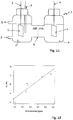
- the figure 2 schematizes another embodiment of an electrochemical device according to the invention.
- the electrochemical device 21 is a dual compartment electrolyser comprising a bioanode 22 and a biocathode 35 formed of graphite granules 20 connected to the external electrical circuit by graphite rods.
- the anode 28 and cathode compartments 39 are separated by a cation exchange membrane 24 (ECM).
- ECM cation exchange membrane 24
- the anode compartment 28 has an inlet 23 and an electrolyte outlet 10A, for example connected to pumping means (not shown).
- the cathode compartment 39 has an inlet 30 and an electrolyte outlet 31 10C that can be connected to pumping means (not shown) independent of the pumping means connected to the anode compartment.
- This device makes it possible to independently modulate the level 26 of electrolyte 10 in the anode compartment and the level 36 of electrolyte 10C in the cathode compartment, thus the volume of electrolyte in each of the compartments and thus to adjust the ratio of the active surfaces (that is to say, immersed) of the two bioelectrodes.
- this modulation makes it possible to vary the potential difference (E) between the two bioelectrodes. This allows, at first, when starting the system, to have anode potential compatible with the establishment of an electroactive biological activity. In a second step, this makes it possible to control the biosynthesis reactions at the cathode regulating its potential.
- the electrochemical device 21 is a double compartment electrolyser such as that presented in FIG. figure 2 comprising a bioanode 22 and a biocathode 35 formed of graphite granules connected to the external electrical circuit by graphite rods.
- the anode 28 and cathode compartments 39 are separated by a cation exchange membrane 24 (ECM).
- ECM cation exchange membrane 24
- the anode compartment 28 has an inlet 23 and an electrolyte outlet 10A, for example connected to pumping means (not shown).
- the cathode compartment 39 has an inlet 30 and an electrolyte outlet 31 10C that can be connected to pumping means (not shown) independent of the pumping means connected to the anode compartment.
- the embodiment of the method of the present invention is here to modulate the potential difference between the anode 22 and the cathode 35 through the use of a potentiostat to control the intensity.
- the maximum intensities obtained reach values of 5, 13 and 20 mA respectively for applied potential differences of 0.5, 1 and 1.5 V, confirming the increase in the intensity measured as a function of the increase in potential difference applied between the bioanode and the granular biocathode.
- the control of the potential difference between bioanode and biocathode thus makes it possible to regulate the intensity of the current in the double compartment bioelectrochemical reactor comprising electrodes formed of graphite granules and consequently the activity of the biocathode.
- the electrochemical device is a double compartment electrolyser comprising a bioanode and a biocathode and a system for supplying and withdrawing the liquid phase.
- the anode compartment has an input E and an electrolyte output S, connected to pumping means (not shown) for a continuous supply of the electrolyte in this compartment.
- the anode compartment of a reactor was fed continuously with bio-waste (from the substrate composition shown in Table 1 of Example 4) by means of a pump making it possible to regulate the inflow and outflow.
- a surge system to maintain a constant liquid level within the anode compartment maintained at a volume of 1 L.
- the impact of different substrate concentrations in the feed (COD load: chemical oxygen demand) on the intensity was tested for an average flow rate of 82 mL / day over an average duration of 10 days. The results are presented on the figure 12 .
Landscapes
- Chemical & Material Sciences (AREA)
- Engineering & Computer Science (AREA)
- Organic Chemistry (AREA)
- Chemical Kinetics & Catalysis (AREA)
- Electrochemistry (AREA)
- Materials Engineering (AREA)
- Metallurgy (AREA)
- Life Sciences & Earth Sciences (AREA)
- Analytical Chemistry (AREA)
- Health & Medical Sciences (AREA)
- Zoology (AREA)
- Bioinformatics & Cheminformatics (AREA)
- Biochemistry (AREA)
- Microbiology (AREA)
- Sustainable Development (AREA)
- Wood Science & Technology (AREA)
- Automation & Control Theory (AREA)
- Inorganic Chemistry (AREA)
- Biotechnology (AREA)
- Biomedical Technology (AREA)
- General Engineering & Computer Science (AREA)
- General Health & Medical Sciences (AREA)
- Genetics & Genomics (AREA)
- Manufacturing & Machinery (AREA)
- Sustainable Energy (AREA)
- General Chemical & Material Sciences (AREA)
- Computer Hardware Design (AREA)
- Electrolytic Production Of Non-Metals, Compounds, Apparatuses Therefor (AREA)
- Apparatus Associated With Microorganisms And Enzymes (AREA)
- Micro-Organisms Or Cultivation Processes Thereof (AREA)
Claims (18)
- Verfahren zur Steuerung der Aktivität einer elektrochemischen Vorrichtung (1), umfassend eine Anode (3) und eine Kathode (6), die in einen Elektrolyt getaucht sind bzw. in einem anodischen Raum (8) und einem kathodischen Raum (9) angeordnet sind, die durch mindestens eine Membran getrennt (4) oder miteinander durch eine Salzbrücke verbunden sind, wobei die Vorrichtung eventuell eine Referenzelektrode (7) umfasst, wobei eine Potenzialdifferenz zwischen der Anode und der Kathode oder zwischen der Anode und der Referenzelektrode angelegt ist,
dadurch gekennzeichnet, dass der Elektrolyt (10A) des anodischen Raums, ebenso wie der Elektrolyt (10C) des kathodischen Raums Mikroorganismen in Suspension oder in Form eines Biofilms/von Biofilmen enthalten, wobei die Elektroden als Bioanode bzw. Biokathode bezeichnet werden, und dadurch, dass die Funktion der Vorrichtung durch eine doppelte Steuerung bestimmt wird:- eine erste Steuerung, genannt prioritäre Steuerung, der Potenzialdifferenz zwischen der Bioanode und der Biokathode oder zwischen der Bioanode und der Referenzelektrode, zwischen einem minimalen Grenzwert, der die Entwicklung eines elektroaktiven Biofilms an der Bioanode ermöglicht und einem maximalen Grenzwert, der unter dem Oxidationspotenzial des Biofilm liegt, und- eine zweite Steuerung, genannt sekundäre Steuerung, wenn die erste Steuerung durchgeführt wird, die die faradaische Leitsung der Biokathode optimiert. - Verfahren nach Anspruch 1,
dadurch gekennzeichnet, dass, unter Beibehaltung der Steuerung des Potenzials an der Bioanode die Optimierung der Aktivität der Biokathode angesichts der Produktion von besonderen chemischen Spezies physisch-chemischen Parametern unterworfen ist, die auf der Ebene des kathodischen Raums (9) gemessen werden, wie z. B. die Konzentration von einer oder mehreren chemischen Spezies im Elektrolyt oder in der gasförmigen Glocke, die die Biokathode umgibt, oder im Gasproduktionsdurchsatz an der Biokathode. - Verfahren nach Anspruch 1 oder 2,
dadurch gekennzeichnet, dass, unter Beibehaltung der ersten Steuerung der Potenzialdifferenz, die die biologische Aktivität auf der Ebene der Bioanode verwaltet, die zweite Steuerung die Optimierung der Stromdichte an der Biokathode angesichts der Produktion von besonderen chemischen Spezies auf der Ebene der Biokathode bestimmt. - Verfahren nach Anspruch 3,
dadurch gekennzeichnet, dass die Optimierung der Stromdichte an der Biokathode mit Hilfe einer elektronischen Vorrichtung durchgeführt wird, die ermöglicht, direkt die Stromdichte an der Biokathode zu fixieren, und/oder mit Hilfe eines Spannungsgenerators oder eines Potentiostats, der ermöglicht, vorzugsweise mit einer Präzision von einigen Millivolt, das Potenzial der Bioanode, der Biokathode und/oder die Potenzialdifferenz zwischen der Bioanode und der Biokathode zu variieren. - Verfahren nach Anspruch 3 oder 4,
dadurch gekennzeichnet, dass die Optimierung der Stromdichte an der Biokathode durch Variationen des Bezugs der aktiven Fläche der Bioanode zur aktiven Fläche der Biokathode durchgeführt wird. - Verfahren nach Anspruch 5,
dadurch gekennzeichnet, dass die Variationen des Bezugs der aktiven Fläche der Bioanode zur aktiven Fläche der Biokathode durch Variationen der eingetauchten Fläche der Bioanode und/oder der Biokathode durchgeführt werden. - Verfahren nach Anspruch 6,
dadurch gekennzeichnet, dass die Variationen der eingetauchten Fläche der Bioanode und/oder der Biokathode durch Variationen des Niveaus des Elektrolyten im anodischen Raum und/oder im kathodischen Raum erhalten werden. - Verfahren nach Anspruch 6 oder 7,
dadurch gekennzeichnet, dass die Variationen der aktiven Fläche der Bioanode und/oder der Biokathode durch Verschiebungen der Bioanode und/oder der Biokathode im Elektrolyt erhalten werden. - Verfahren nach einem der Ansprüche 5 bis 8,
dadurch gekennzeichnet, dass die Variationen des Bezugs der aktiven Fläche der Bioanode zur aktiven Fläche der Biokathode durch die Änderung de Anzahl der Bioanoden im anodischen Raum und/oder die Änderung der Anzahl der Biokathoden im kathodischen Raum durchgeführt werden. - Verfahren nach einem der vorhergehenden Ansprüche,
dadurch gekennzeichnet, dass, unter Beibehaltung der Steuerung des Potenzials an der Bioanode die Optimierung der Aktivität der Biokathode angesichts der Produktion von besonderen chemischen Spezies durch die Steuerung von chemischen Parametern auf der Ebene des anodischen Raums wie z. B. der Konzentration von einer oder mehreren chemischen Spezies im Elektrolyt oder in der gasförmigen Glocke, die die Biokathode umgibt, durchgeführt wird. - Verfahren nach Anspruch 2, dadurch gekennzeichnet, dass die chemische Spezies Dihydrogen ist.
- Verfahren nach Anspruch 2, dadurch gekennzeichnet, dass die chemische Spezies Methan ist.
- Verfahren nach Anspruch 10, dadurch gekennzeichnet, dass die chemische Spezies ein nicht fermentierbares Molekül ist, wie z. B. eine organische Säure oder ihr Salz, vorzugsweise ausgewählt aus Acetat, Lactat oder Propionat.
- Verfahren nach einem der vorhergehenden Ansprüche, dadurch gekennzeichnet, dass wenn die Bioanode, wie z. B eine Elektrode aus Kohlenstoff, in einen wässrigen Elektrolyt mit einem pH von ungefähr 7 eingetaucht ist, der maximale Wert der Potenzialdifferenz zwischen der Bioanode und einer normalen Wasserstoffelektrode, genannt Referenzelektrode, derart ist, dass das Potenzial der Bioanode kleiner oder gleich 1 V mit Bezug auf die Referenzelektrode, vorzugsweise kleiner oder gleich 0,5 V mit Bezug auf die Referenzelektrode ist, um die Elektrolyse des Wassers zu vermeiden.
- Elektrochemische Vorrichtung (1) zur Durchführung des Verfahrens nach einem der vorhergehenden Ansprüche, umfassend:- eine Anode (3) und eine Kathode (6), die in einen Elektrolyt getaucht sind bzw. in einem anodischen Raum (8; 28) und einem kathodischen Raum (9; 29) angeordnet sind, die durch mindestens eine Membran getrennt (4 ;14 ;24) oder miteinander durch eine Salzbrücke verbunden sind, wobei der Elektrolyt (10A) des anodischen Raums Mikroorganismen enthält, ebenso wie der Elektrolyt (10C) des kathodischen Raums, wobei die Elektroden als Bioanode bzw. Biokathode bezeichnet werden,- eventuell eine Referenzelektrode (7),- Mittel, die ermöglichen, eine Potenzialdifferenz zwischen der Bioanode und der Biokathode oder zwischen der Bioanode und der Referenzelektrode anzulegen- wobei die Bioanode und die Biokathode mit einer elektronidchen Vorrichtung zur Steuerung dieser Potenzialdifferenz verbunden sind, dadurch gekennzeichnet, dass es Mittel umfasst, die es ermöglichen, die faradaische Leistung der Biokathode zu optimieren, wobei die Mittel Sensoren oder Sonden umfassen, die sich im Elektrolyt (10A, 10C) und/oder in der Gasglocke (12, 15) befinden, die die Bioanode (3) oder die Biokathode (6) umgibt, wobei die Sensoren oder Sonden physisch-chemische Parameter auf der Ebene des anodischen Raums (28) und/oder des kathodischen Raums (39) messen, wie z. B. die Konzentration von einer oder mehreren chemischen Spezies
- Elektrochemische Vorrichtung nach Anspruch 15, dadurch gekennzeichnet, dass die Sensoren (13, 16) oder Sonden (18, 19) mit der elektronischen Vorrichtung (17) verbunden sind.
- Elektrochemische Vorrichtung nach einem der Ansprüche 15 oder 16, dadurch gekennzeichnet, dass der anodische (28) und kathodische (39) Raum durch eine Kationentauschermembran (24) getrennt sind, wobei der anodische Raum einen Eingang (23) und einen Ausgang (25) von Elektrolyt umfasst, die mit Pumpmitteln von Elektrolyt verbunden sind, wobei der kathodische Raum einen Eingang (30) und einen Ausgang (31) von Elektrolyt umfasst, die mit Pumpmitteln verbunden sind, die unabhängig von den Pumpmitteln sind, die mit dem anodischen Raum verbunden sind.
- Elektrochemische Vorrichtung nach einem der Ansprüche 15 bis 17, dadurch gekennzeichnet, dass sie Mittel zur Verschiebung der Bioanode (3) und/oder der Biokathode (6) im Elektorolyten umfasst, die ermöglichen, die eingetauchte Fläche der Bioanode und/oder der Biokathode zu variieren.
Applications Claiming Priority (2)
| Application Number | Priority Date | Filing Date | Title |
|---|---|---|---|
| FR1459281A FR3026413B1 (fr) | 2014-09-30 | 2014-09-30 | Procede et dispositif de regulation de l'activite d'un systeme bioelectrochimique comportant a la fois une bioanode et une biocathode |
| PCT/FR2015/052585 WO2016051064A1 (fr) | 2014-09-30 | 2015-09-29 | Procede et dispositif de regulation de l'activite d'un systeme bioelectrochimique comportant a la fois une bioanode et une biocathode |
Publications (2)
| Publication Number | Publication Date |
|---|---|
| EP3201374A1 EP3201374A1 (de) | 2017-08-09 |
| EP3201374B1 true EP3201374B1 (de) | 2019-11-06 |
Family
ID=52102830
Family Applications (1)
| Application Number | Title | Priority Date | Filing Date |
|---|---|---|---|
| EP15787256.5A Active EP3201374B1 (de) | 2014-09-30 | 2015-09-29 | Verfahren und vorrichtung zur steuerung der aktivität eines bioelektrochemischen systems mit einer bioanode und biokathode |
Country Status (6)
| Country | Link |
|---|---|
| US (1) | US10329678B2 (de) |
| EP (1) | EP3201374B1 (de) |
| AU (1) | AU2015326725B2 (de) |
| ES (1) | ES2772178T3 (de) |
| FR (1) | FR3026413B1 (de) |
| WO (1) | WO2016051064A1 (de) |
Families Citing this family (12)
| Publication number | Priority date | Publication date | Assignee | Title |
|---|---|---|---|---|
| US10164282B2 (en) * | 2016-11-13 | 2018-12-25 | Soheil Bahrebar | Microbial fuel cells and methods for generating an electric current |
| JP7174521B2 (ja) * | 2017-12-05 | 2022-11-17 | 住友重機械工業株式会社 | 微生物活性測定センサ及び微生物活性の評価方法 |
| FR3085970B1 (fr) | 2018-09-13 | 2022-07-22 | Suez Groupe | Regeneration d'une bio-electrode d'un dispositif bio-electrochimique - dispositif et procede associe |
| FR3085969B1 (fr) | 2018-09-13 | 2020-09-11 | Institut National De Recherche En Sciences Et Tech Pour Lenvironnement Et Lagriculture Irstea | Procede de regeneration in situ d'une bio-anode d'un dispositif de synthese bio-electrochimique |
| FR3085972B1 (fr) | 2018-09-13 | 2020-09-11 | Suez Groupe | Reacteur bio-electrochimique a double bio-anode, procede de regeneration anodique et utilisation du reacteur a l'electrosynthese microbienne |
| FR3085971B1 (fr) | 2018-09-13 | 2020-09-11 | Institut National De Recherche En Sciences Et Tech Pour Lenvironnement Et Lagriculture Irstea | Reacteur bio-electrochimique comportant une bio-anode et une anode abiotique et son utilisation pour l'electrosynthese microbienne |
| CN109813634B (zh) * | 2019-01-01 | 2021-07-20 | 中国人民解放军63653部队 | 用于获取核素迁移参数的改进电迁移实验方法 |
| GB201900605D0 (en) | 2019-01-16 | 2019-03-06 | Univ Durham | An electrochemical capacitor device for use with a biofilm |
| CN110776097A (zh) * | 2019-11-28 | 2020-02-11 | 天津工业大学 | 用于废水脱氮除碳的反硝化生物阴极-电催化膜反应器 |
| CN111514741B (zh) * | 2020-04-07 | 2023-12-05 | 武汉科技大学 | 一种组装式生物电化学反应装置 |
| CN114813873B (zh) * | 2022-04-18 | 2024-03-26 | 中国科学院重庆绿色智能技术研究院 | 一种微生物电化学分析装置及其分析方法 |
| CN117030821B (zh) * | 2023-03-07 | 2026-04-24 | 福建农林大学 | 一种微生物电位传感器及其在水质预警中的应用 |
Family Cites Families (4)
| Publication number | Priority date | Publication date | Assignee | Title |
|---|---|---|---|---|
| GB8418775D0 (en) * | 1984-07-24 | 1984-08-30 | Queen Elizabeth College | Operation of microbial fuel cells |
| FR2843490B1 (fr) * | 2002-08-06 | 2004-09-03 | Centre Nat Rech Scient | Pile a combustible utilisant des biofilms en tant que catalyseur de la reaction cathodique et/ou de la reaction anodique |
| NL1034123C2 (nl) * | 2007-07-12 | 2009-01-13 | Stichting Wetsus Ct Of Excelle | Werkwijze voor het verkrijgen van een kathodofiele, waterstof producerende microbiele cultuur, microbiele cultuur verkregen met deze werkwijze en gebruik van deze microbiele cultuur. |
| CN102925492A (zh) * | 2012-11-09 | 2013-02-13 | 中国科学院成都生物研究所 | 一种利用生物电化学系统还原二氧化碳生产甲烷和乙酸的方法 |
-
2014
- 2014-09-30 FR FR1459281A patent/FR3026413B1/fr active Active
-
2015
- 2015-09-29 EP EP15787256.5A patent/EP3201374B1/de active Active
- 2015-09-29 WO PCT/FR2015/052585 patent/WO2016051064A1/fr not_active Ceased
- 2015-09-29 US US15/515,393 patent/US10329678B2/en active Active
- 2015-09-29 ES ES15787256T patent/ES2772178T3/es active Active
- 2015-09-29 AU AU2015326725A patent/AU2015326725B2/en not_active Expired - Fee Related
Non-Patent Citations (1)
| Title |
|---|
| None * |
Also Published As
| Publication number | Publication date |
|---|---|
| FR3026413B1 (fr) | 2023-05-12 |
| US20170218530A1 (en) | 2017-08-03 |
| US10329678B2 (en) | 2019-06-25 |
| AU2015326725B2 (en) | 2020-01-30 |
| EP3201374A1 (de) | 2017-08-09 |
| ES2772178T3 (es) | 2020-07-07 |
| AU2015326725A1 (en) | 2017-04-20 |
| WO2016051064A1 (fr) | 2016-04-07 |
| FR3026413A1 (fr) | 2016-04-01 |
Similar Documents
| Publication | Publication Date | Title |
|---|---|---|
| WO2016051064A1 (fr) | Procede et dispositif de regulation de l'activite d'un systeme bioelectrochimique comportant a la fois une bioanode et une biocathode | |
| Chu et al. | Electricity-driven microbial metabolism of carbon and nitrogen: a waste-to-resource solution | |
| Rojas et al. | Effect of the electric supply interruption on a microbial electrosynthesis system converting inorganic carbon into acetate | |
| Timmers et al. | Characterization of the internal resistance of a plant microbial fuel cell | |
| Parameswaran et al. | Kinetic, electrochemical, and microscopic characterization of the thermophilic, anode-respiring bacterium Thermincola ferriacetica | |
| Bajracharya et al. | Carbon dioxide reduction by mixed and pure cultures in microbial electrosynthesis using an assembly of graphite felt and stainless steel as a cathode | |
| Cercado-Quezada et al. | Testing various food-industry wastes for electricity production in microbial fuel cell | |
| Paiano et al. | Electro-fermentation and redox mediators enhance glucose conversion into butyric acid with mixed microbial cultures | |
| EP2047011B1 (de) | Wasserelektrolysevorrichtung | |
| FR3085972A1 (fr) | Reacteur bio-electrochimique a double bio-anode, procede de regeneration anodique et utilisation du reacteur a l'electrosynthese microbienne | |
| EP2379780B1 (de) | Neues elektrochemisches verfahren zur herstellung von wasserstoff und vorrichtung zu seiner durchführung | |
| Wu et al. | Acetate-to-bioproducts by chain elongation microbiome catalysis under applied voltage regulation | |
| KR102193010B1 (ko) | 생물학적 c1 가스 전환 공정을 위한 생물전기화학반응기 및 이를 이용한 공정방법 | |
| EP2294648B1 (de) | Herstellung einer bioschicht auf einer elektrode für eine biozelle, elektrode und hergestellte biozelle | |
| Guimarães et al. | Glycerol utilization in microbial fuel cells: conditioning stage and influence of the glycerol concentration | |
| WO2020053528A1 (fr) | Procédé de régénération in situ d'une bio-anode d'un dispositif de synthèse bio-électrochimique | |
| FR2979356A1 (fr) | Procede de reduction electrochimique du co2 catalysee par un biofilm electrochimiquement actif | |
| Ryzhkov et al. | Electric Polarization-Dependent Absorption and Photocurrent Generation in Limnospira indica Immobilized on Boron-Doped Diamond | |
| Lee et al. | Production of Lactic Acid Directly from CO2 by a Bioelectro-Hybrid System | |
| Reddy et al. | Potential stage in wastewater treatment for generation of bioelectricity using MFC | |
| WO2026082916A1 (fr) | Procédé de production bio-électrochimique de méthane et/ou d'acétate au moyen d'un électrolyseur microbien et système associé | |
| FR3085971A1 (fr) | Reacteur bio-electrochimique comportant une bio-anode et une anode abiotique et son utilisation pour l'electrosynthese microbienne | |
| Kornienko et al. | Indirect electrocatalytic oxidation of glycerin on platinum electrode in acidic electrolyte involving active oxygen forms | |
| FR3085970A1 (fr) | Regeneration d'une bio-electrode d'un dispositif bio-electrochimique - dispositif et procede associe | |
| WO2019234344A1 (fr) | Procédé de valorisation du co2 par réduction biologique |
Legal Events
| Date | Code | Title | Description |
|---|---|---|---|
| STAA | Information on the status of an ep patent application or granted ep patent |
Free format text: STATUS: THE INTERNATIONAL PUBLICATION HAS BEEN MADE |
|
| PUAI | Public reference made under article 153(3) epc to a published international application that has entered the european phase |
Free format text: ORIGINAL CODE: 0009012 |
|
| STAA | Information on the status of an ep patent application or granted ep patent |
Free format text: STATUS: REQUEST FOR EXAMINATION WAS MADE |
|
| 17P | Request for examination filed |
Effective date: 20170405 |
|
| AK | Designated contracting states |
Kind code of ref document: A1 Designated state(s): AL AT BE BG CH CY CZ DE DK EE ES FI FR GB GR HR HU IE IS IT LI LT LU LV MC MK MT NL NO PL PT RO RS SE SI SK SM TR |
|
| AX | Request for extension of the european patent |
Extension state: BA ME |
|
| DAV | Request for validation of the european patent (deleted) | ||
| DAX | Request for extension of the european patent (deleted) | ||
| GRAP | Despatch of communication of intention to grant a patent |
Free format text: ORIGINAL CODE: EPIDOSNIGR1 |
|
| STAA | Information on the status of an ep patent application or granted ep patent |
Free format text: STATUS: GRANT OF PATENT IS INTENDED |
|
| INTG | Intention to grant announced |
Effective date: 20190802 |
|
| GRAS | Grant fee paid |
Free format text: ORIGINAL CODE: EPIDOSNIGR3 |
|
| GRAA | (expected) grant |
Free format text: ORIGINAL CODE: 0009210 |
|
| STAA | Information on the status of an ep patent application or granted ep patent |
Free format text: STATUS: THE PATENT HAS BEEN GRANTED |
|
| AK | Designated contracting states |
Kind code of ref document: B1 Designated state(s): AL AT BE BG CH CY CZ DE DK EE ES FI FR GB GR HR HU IE IS IT LI LT LU LV MC MK MT NL NO PL PT RO RS SE SI SK SM TR |
|
| REG | Reference to a national code |
Ref country code: GB Ref legal event code: FG4D Free format text: NOT ENGLISH |
|
| REG | Reference to a national code |
Ref country code: CH Ref legal event code: EP Ref country code: AT Ref legal event code: REF Ref document number: 1198829 Country of ref document: AT Kind code of ref document: T Effective date: 20191115 |
|
| REG | Reference to a national code |
Ref country code: DE Ref legal event code: R096 Ref document number: 602015041253 Country of ref document: DE |
|
| REG | Reference to a national code |
Ref country code: IE Ref legal event code: FG4D Free format text: LANGUAGE OF EP DOCUMENT: FRENCH |
|
| REG | Reference to a national code |
Ref country code: NL Ref legal event code: FP |
|
| REG | Reference to a national code |
Ref country code: LT Ref legal event code: MG4D |
|
| RAP2 | Party data changed (patent owner data changed or rights of a patent transferred) |
Owner name: INSTITUT NATIONAL DE RECHERCHE POUR L'AGRICULTURE, L'ALIMENTATION ET L'ENVIRONNEMENT |
|
| PG25 | Lapsed in a contracting state [announced via postgrant information from national office to epo] |
Ref country code: LV Free format text: LAPSE BECAUSE OF FAILURE TO SUBMIT A TRANSLATION OF THE DESCRIPTION OR TO PAY THE FEE WITHIN THE PRESCRIBED TIME-LIMIT Effective date: 20191106 Ref country code: SE Free format text: LAPSE BECAUSE OF FAILURE TO SUBMIT A TRANSLATION OF THE DESCRIPTION OR TO PAY THE FEE WITHIN THE PRESCRIBED TIME-LIMIT Effective date: 20191106 Ref country code: NO Free format text: LAPSE BECAUSE OF FAILURE TO SUBMIT A TRANSLATION OF THE DESCRIPTION OR TO PAY THE FEE WITHIN THE PRESCRIBED TIME-LIMIT Effective date: 20200206 Ref country code: PT Free format text: LAPSE BECAUSE OF FAILURE TO SUBMIT A TRANSLATION OF THE DESCRIPTION OR TO PAY THE FEE WITHIN THE PRESCRIBED TIME-LIMIT Effective date: 20200306 Ref country code: GR Free format text: LAPSE BECAUSE OF FAILURE TO SUBMIT A TRANSLATION OF THE DESCRIPTION OR TO PAY THE FEE WITHIN THE PRESCRIBED TIME-LIMIT Effective date: 20200207 Ref country code: PL Free format text: LAPSE BECAUSE OF FAILURE TO SUBMIT A TRANSLATION OF THE DESCRIPTION OR TO PAY THE FEE WITHIN THE PRESCRIBED TIME-LIMIT Effective date: 20191106 Ref country code: LT Free format text: LAPSE BECAUSE OF FAILURE TO SUBMIT A TRANSLATION OF THE DESCRIPTION OR TO PAY THE FEE WITHIN THE PRESCRIBED TIME-LIMIT Effective date: 20191106 Ref country code: BG Free format text: LAPSE BECAUSE OF FAILURE TO SUBMIT A TRANSLATION OF THE DESCRIPTION OR TO PAY THE FEE WITHIN THE PRESCRIBED TIME-LIMIT Effective date: 20200206 Ref country code: FI Free format text: LAPSE BECAUSE OF FAILURE TO SUBMIT A TRANSLATION OF THE DESCRIPTION OR TO PAY THE FEE WITHIN THE PRESCRIBED TIME-LIMIT Effective date: 20191106 |
|
| PG25 | Lapsed in a contracting state [announced via postgrant information from national office to epo] |
Ref country code: IS Free format text: LAPSE BECAUSE OF FAILURE TO SUBMIT A TRANSLATION OF THE DESCRIPTION OR TO PAY THE FEE WITHIN THE PRESCRIBED TIME-LIMIT Effective date: 20200306 Ref country code: HR Free format text: LAPSE BECAUSE OF FAILURE TO SUBMIT A TRANSLATION OF THE DESCRIPTION OR TO PAY THE FEE WITHIN THE PRESCRIBED TIME-LIMIT Effective date: 20191106 Ref country code: RS Free format text: LAPSE BECAUSE OF FAILURE TO SUBMIT A TRANSLATION OF THE DESCRIPTION OR TO PAY THE FEE WITHIN THE PRESCRIBED TIME-LIMIT Effective date: 20191106 |
|
| PG25 | Lapsed in a contracting state [announced via postgrant information from national office to epo] |
Ref country code: AL Free format text: LAPSE BECAUSE OF FAILURE TO SUBMIT A TRANSLATION OF THE DESCRIPTION OR TO PAY THE FEE WITHIN THE PRESCRIBED TIME-LIMIT Effective date: 20191106 |
|
| REG | Reference to a national code |
Ref country code: ES Ref legal event code: FG2A Ref document number: 2772178 Country of ref document: ES Kind code of ref document: T3 Effective date: 20200707 |
|
| PG25 | Lapsed in a contracting state [announced via postgrant information from national office to epo] |
Ref country code: DK Free format text: LAPSE BECAUSE OF FAILURE TO SUBMIT A TRANSLATION OF THE DESCRIPTION OR TO PAY THE FEE WITHIN THE PRESCRIBED TIME-LIMIT Effective date: 20191106 Ref country code: EE Free format text: LAPSE BECAUSE OF FAILURE TO SUBMIT A TRANSLATION OF THE DESCRIPTION OR TO PAY THE FEE WITHIN THE PRESCRIBED TIME-LIMIT Effective date: 20191106 Ref country code: RO Free format text: LAPSE BECAUSE OF FAILURE TO SUBMIT A TRANSLATION OF THE DESCRIPTION OR TO PAY THE FEE WITHIN THE PRESCRIBED TIME-LIMIT Effective date: 20191106 Ref country code: CZ Free format text: LAPSE BECAUSE OF FAILURE TO SUBMIT A TRANSLATION OF THE DESCRIPTION OR TO PAY THE FEE WITHIN THE PRESCRIBED TIME-LIMIT Effective date: 20191106 |
|
| REG | Reference to a national code |
Ref country code: DE Ref legal event code: R097 Ref document number: 602015041253 Country of ref document: DE |
|
| REG | Reference to a national code |
Ref country code: BE Ref legal event code: PD Owner name: INSTITUT NATIONAL DE RECHERCHE POUR L'AGRICULTURE, L'ALIMENTATION ET L'ENVIRONNEMENT; FR Free format text: DETAILS ASSIGNMENT: CHANGE OF OWNER(S), CESSION; FORMER OWNER NAME: INSTITUT NATIONAL DE RECHERCHE EN SCIENCES ET TECHNOLOGIES POUR L'ENVIRONNEMENT ET L'AGRICULTURE (IRSTEA) Effective date: 20200505 |
|
| REG | Reference to a national code |
Ref country code: AT Ref legal event code: MK05 Ref document number: 1198829 Country of ref document: AT Kind code of ref document: T Effective date: 20191106 |
|
| PG25 | Lapsed in a contracting state [announced via postgrant information from national office to epo] |
Ref country code: SK Free format text: LAPSE BECAUSE OF FAILURE TO SUBMIT A TRANSLATION OF THE DESCRIPTION OR TO PAY THE FEE WITHIN THE PRESCRIBED TIME-LIMIT Effective date: 20191106 Ref country code: SM Free format text: LAPSE BECAUSE OF FAILURE TO SUBMIT A TRANSLATION OF THE DESCRIPTION OR TO PAY THE FEE WITHIN THE PRESCRIBED TIME-LIMIT Effective date: 20191106 |
|
| PLBE | No opposition filed within time limit |
Free format text: ORIGINAL CODE: 0009261 |
|
| STAA | Information on the status of an ep patent application or granted ep patent |
Free format text: STATUS: NO OPPOSITION FILED WITHIN TIME LIMIT |
|
| 26N | No opposition filed |
Effective date: 20200807 |
|
| PG25 | Lapsed in a contracting state [announced via postgrant information from national office to epo] |
Ref country code: AT Free format text: LAPSE BECAUSE OF FAILURE TO SUBMIT A TRANSLATION OF THE DESCRIPTION OR TO PAY THE FEE WITHIN THE PRESCRIBED TIME-LIMIT Effective date: 20191106 Ref country code: SI Free format text: LAPSE BECAUSE OF FAILURE TO SUBMIT A TRANSLATION OF THE DESCRIPTION OR TO PAY THE FEE WITHIN THE PRESCRIBED TIME-LIMIT Effective date: 20191106 |
|
| REG | Reference to a national code |
Ref country code: DE Ref legal event code: R081 Ref document number: 602015041253 Country of ref document: DE Owner name: INSTITUT NATIONAL DE RECHERCHE POUR L'AGRICULT, FR Free format text: FORMER OWNER: INSTITUT NATIONAL DE RECHERCHE EN SCIENCES ET TECHNOLOGIES POUR L'ENVIRONNEMENT ET L'AGRICULTURE (IRSTEA), ANTONY, FR |
|
| REG | Reference to a national code |
Ref country code: NL Ref legal event code: PD Owner name: INSTITUT NATIONAL DE RECHERCHE POUR L'AGRICULTURE, L'ALIMENTATION ET L'ENVIRONNEMENT; FR Free format text: DETAILS ASSIGNMENT: CHANGE OF OWNER(S), MERGE; FORMER OWNER NAME: INSTITUT NATIONAL DE RECHERCHE EN SCIENCES ET TECHNOLOGIES POUR L'ENVIRONNEMENT ET L'AGRICULTURE (IRSTEA) Effective date: 20201210 |
|
| REG | Reference to a national code |
Ref country code: GB Ref legal event code: 732E Free format text: REGISTERED BETWEEN 20210121 AND 20210127 |
|
| PG25 | Lapsed in a contracting state [announced via postgrant information from national office to epo] |
Ref country code: MC Free format text: LAPSE BECAUSE OF FAILURE TO SUBMIT A TRANSLATION OF THE DESCRIPTION OR TO PAY THE FEE WITHIN THE PRESCRIBED TIME-LIMIT Effective date: 20191106 |
|
| REG | Reference to a national code |
Ref country code: CH Ref legal event code: PL |
|
| PG25 | Lapsed in a contracting state [announced via postgrant information from national office to epo] |
Ref country code: LU Free format text: LAPSE BECAUSE OF NON-PAYMENT OF DUE FEES Effective date: 20200929 |
|
| PG25 | Lapsed in a contracting state [announced via postgrant information from national office to epo] |
Ref country code: LI Free format text: LAPSE BECAUSE OF NON-PAYMENT OF DUE FEES Effective date: 20200930 Ref country code: IE Free format text: LAPSE BECAUSE OF NON-PAYMENT OF DUE FEES Effective date: 20200929 Ref country code: CH Free format text: LAPSE BECAUSE OF NON-PAYMENT OF DUE FEES Effective date: 20200930 |
|
| PG25 | Lapsed in a contracting state [announced via postgrant information from national office to epo] |
Ref country code: TR Free format text: LAPSE BECAUSE OF FAILURE TO SUBMIT A TRANSLATION OF THE DESCRIPTION OR TO PAY THE FEE WITHIN THE PRESCRIBED TIME-LIMIT Effective date: 20191106 Ref country code: MT Free format text: LAPSE BECAUSE OF FAILURE TO SUBMIT A TRANSLATION OF THE DESCRIPTION OR TO PAY THE FEE WITHIN THE PRESCRIBED TIME-LIMIT Effective date: 20191106 Ref country code: CY Free format text: LAPSE BECAUSE OF FAILURE TO SUBMIT A TRANSLATION OF THE DESCRIPTION OR TO PAY THE FEE WITHIN THE PRESCRIBED TIME-LIMIT Effective date: 20191106 |
|
| PG25 | Lapsed in a contracting state [announced via postgrant information from national office to epo] |
Ref country code: MK Free format text: LAPSE BECAUSE OF FAILURE TO SUBMIT A TRANSLATION OF THE DESCRIPTION OR TO PAY THE FEE WITHIN THE PRESCRIBED TIME-LIMIT Effective date: 20191106 |
|
| PGFP | Annual fee paid to national office [announced via postgrant information from national office to epo] |
Ref country code: DE Payment date: 20250919 Year of fee payment: 11 |
|
| PGFP | Annual fee paid to national office [announced via postgrant information from national office to epo] |
Ref country code: NL Payment date: 20250918 Year of fee payment: 11 Ref country code: IT Payment date: 20250923 Year of fee payment: 11 |
|
| PGFP | Annual fee paid to national office [announced via postgrant information from national office to epo] |
Ref country code: BE Payment date: 20250918 Year of fee payment: 11 Ref country code: GB Payment date: 20250919 Year of fee payment: 11 |
|
| PGFP | Annual fee paid to national office [announced via postgrant information from national office to epo] |
Ref country code: FR Payment date: 20250926 Year of fee payment: 11 |
|
| PGFP | Annual fee paid to national office [announced via postgrant information from national office to epo] |
Ref country code: ES Payment date: 20251028 Year of fee payment: 11 |