EP3199706A1 - Pre-fabricated water control sluice gate system - Google Patents
Pre-fabricated water control sluice gate system Download PDFInfo
- Publication number
- EP3199706A1 EP3199706A1 EP17151959.8A EP17151959A EP3199706A1 EP 3199706 A1 EP3199706 A1 EP 3199706A1 EP 17151959 A EP17151959 A EP 17151959A EP 3199706 A1 EP3199706 A1 EP 3199706A1
- Authority
- EP
- European Patent Office
- Prior art keywords
- sluice gate
- fabricated
- gate system
- side panels
- water
- Prior art date
- Legal status (The legal status is an assumption and is not a legal conclusion. Google has not performed a legal analysis and makes no representation as to the accuracy of the status listed.)
- Granted
Links
- XLYOFNOQVPJJNP-UHFFFAOYSA-N water Substances O XLYOFNOQVPJJNP-UHFFFAOYSA-N 0.000 title claims abstract description 70
- 230000002787 reinforcement Effects 0.000 claims description 21
- 239000000463 material Substances 0.000 claims description 9
- 238000000034 method Methods 0.000 claims description 5
- 239000011150 reinforced concrete Substances 0.000 description 36
- 230000000630 rising effect Effects 0.000 description 4
- 230000000903 blocking effect Effects 0.000 description 3
- 239000004568 cement Substances 0.000 description 3
- 239000004567 concrete Substances 0.000 description 3
- 239000013049 sediment Substances 0.000 description 3
- 238000005266 casting Methods 0.000 description 1
- 239000000919 ceramic Substances 0.000 description 1
- 238000010276 construction Methods 0.000 description 1
- 238000011065 in-situ storage Methods 0.000 description 1
- 239000002184 metal Substances 0.000 description 1
- 239000004570 mortar (masonry) Substances 0.000 description 1
- 239000011178 precast concrete Substances 0.000 description 1
- 230000003014 reinforcing effect Effects 0.000 description 1
- 229920001169 thermoplastic Polymers 0.000 description 1
- 229920001187 thermosetting polymer Polymers 0.000 description 1
- 239000004416 thermosoftening plastic Substances 0.000 description 1
- 239000002023 wood Substances 0.000 description 1
Images

Classifications
-
- E—FIXED CONSTRUCTIONS
- E02—HYDRAULIC ENGINEERING; FOUNDATIONS; SOIL SHIFTING
- E02C—SHIP-LIFTING DEVICES OR MECHANISMS
- E02C1/00—Locks or dry-docks; Shaft locks, i.e. locks of which one front side is formed by a solid wall with an opening in the lower part through which the ships pass
-
- E—FIXED CONSTRUCTIONS
- E02—HYDRAULIC ENGINEERING; FOUNDATIONS; SOIL SHIFTING
- E02B—HYDRAULIC ENGINEERING
- E02B7/00—Barrages or weirs; Layout, construction, methods of, or devices for, making same
- E02B7/20—Movable barrages; Lock or dry-dock gates
-
- Y—GENERAL TAGGING OF NEW TECHNOLOGICAL DEVELOPMENTS; GENERAL TAGGING OF CROSS-SECTIONAL TECHNOLOGIES SPANNING OVER SEVERAL SECTIONS OF THE IPC; TECHNICAL SUBJECTS COVERED BY FORMER USPC CROSS-REFERENCE ART COLLECTIONS [XRACs] AND DIGESTS
- Y02—TECHNOLOGIES OR APPLICATIONS FOR MITIGATION OR ADAPTATION AGAINST CLIMATE CHANGE
- Y02A—TECHNOLOGIES FOR ADAPTATION TO CLIMATE CHANGE
- Y02A10/00—TECHNOLOGIES FOR ADAPTATION TO CLIMATE CHANGE at coastal zones; at river basins
- Y02A10/30—Flood prevention; Flood or storm water management, e.g. using flood barriers
Definitions
- the present invention relates to sluice gates.
- Sluice gates are used selectively to control water flow from one area of a channel to another by opening or closing off the channel to the water flow.
- the frame/foundation of the sluice gate is cast directly at the application site of the sluice gate.
- the flow of water must be discontinued over the portion of land, where the sluice gate is to be placed, requiring many man hours of preparation before the actual casting process can be initiated.
- the construction time is long, as the cement needs to settle and harden before a sluice gate member can be installed therein.
- the weather conditions may affect the hardening of the cement, resulting in a frame/foundation of poor quality and strength.
- the frame/foundation is susceptible to undermining of the water.
- One aspect relates to a pre-fabricated water control sluice gate system comprising:
- Another aspect relates to a pre-fabricated water control sluice gate system comprising:
- the first frame is a pre-cast concrete frame.
- the first frame is a pre-cast reinforced concrete frame.
- pre-cast as used throughout this application means the opposite of cast in situ.
- the pre-cast reinforced concrete frame is finished as finished structures when shipped to a builder or customer, rather than being poured into temporary forms at the building site or place of use.
- reinforced concrete refers to concrete into which reinforcement bars or fibres have been cast to carry tensile loads in order to strengthen a structure that would otherwise be brittle.
- the first frame may also be made of metal, wood, or a castable material. It is to be understood that any suitable castable material, such as cement, mortar, concrete, ceramics, thermoset plastics, and thermoplastics can be used for producing the first frame.
- the side and/or base panels are made from a reinforced castable material.
- the side and/or base panels are made from a reinforced castable material, and wherein the reinforcement extends beyond the side and/or base panels.
- reinforced castable material refers to a castable material into which reinforcement bars or fibres have been cast to carry tensile loads in order to strengthen a structure that would otherwise be brittle.
- lifting anchor should be broadly construed to encompass any such device for lifting the first frame with or without sluice gate members and actuators installed therein.
- a coupler adapted for receiving a lifting anchor is embedded in the first frame.
- the coupler may comprise internal or external threading, depending on the configuration of the lifting anchor.
- the lifting anchor or coupler adapted for receiving a lifting anchor is mechanically tied into the reinforcing members embedded in the castable material, such as concrete.
- the base panel In order to avoid that water will undermine the base panel; it may be an advantage to extend the base panels beyond the side panels, preferably beyond the front, back and outer side/face of the side panel. In one or more embodiments, the base panel extends beyond the side panels.
- the base panel extends beyond the front of the side panels.
- the base panel extends beyond back of the side panels.
- the base panel extends beyond the outer side/face of the side panels.
- the base panel extends beyond the front and/or the back and/or the outer side of the side panels.
- the part of the base panel extending beyond the side panels comprises channels adapted for receiving an earth anchor.
- the reinforcement extends beyond the side and/or base panels.
- the reinforcement extends beyond the side panels, preferably beyond the front and back of the side panel. This will allow the pre-fabricated sluice gate system to be built into other reinforced concrete structures.
- the reinforcement extends beyond the front of the side panels.
- the reinforcement extends beyond the back of the side panels.
- the reinforcement extends beyond the outer side/face of the side panels.
- the reinforcement extends beyond the front and/or the back and/or the outer side of the side panels.
- a part of the base panel is configured as a lower sluice gate member extending between the two side panels.
- the base panel is preferably pre-cast. This configuration has the advantage, that it increases the strength of the sluice gate against high water levels. A substantial part of the water pressure is thereby withheld by the entire structure of the first frame.
- the lower gate member prevents that water flow passing through the first frame will remove the dirt/foundation below the first frame. The water flow is thereby elevated further away from the dirt/foundation below the first frame; and the water close to the dirt/foundation below the first frame will be stagnant.
- the lower sluice gate member may be positioned in front of the sluice gate members to shield the latter, and/or may be positioned behind the sluice gate members to support the latter.
- the lower sluice gate member has a height of at least 5 cm, such as within the range of 5-100 cm, e.g. within the range of 10-95 cm, such as within the range of 15-90 cm, e.g. within the range of 20-85 cm, such as within the range of 25-80 cm, e.g. within the range of 30-75 cm, such as within the range of 35-70 cm, e.g. within the range of 40-65 cm, such as within the range of 45-60 cm, e.g. within the range of 50-55 cm.
- the lower sluice gate member may in one or more embodiments comprise air/water channels adapted to be connected to a source of water and/or compressed air. Water and/or compressed air may thereby be used to remove sediments blocking the function of the one or more gate members. Icing may also be prevented.
- the outlet of the channels is positioned in close proximity, such as within 0-20 cm, e.g. within 1-15 cm, such as within 2-10 cm, e.g. within 3-5 cm, to the one or more gate members.
- the base panel comprises air/water channels adapted to be connected to a source of water and/or compressed air.
- the pre-fabricated water control sluice gate system further comprises means for delivering water and/or compressed air to the air/water channels.
- the base panel comprises suction channels adapted to be connected to a source of suction.
- the suction channels may be used to remove sediments blocking the function of the one or more gate members. Icing may also be prevented.
- the lower sluice gate member comprises suction channels adapted to be connected to a source of suction.
- the inlet of the suction channels is positioned in close proximity, such as within 0-20 cm, e.g. within 1-15 cm, such as within 2-10 cm, e.g. within 3-5 cm, to the one or more gate members.
- the pre-fabricated water control sluice gate system further comprises a source of suction adapted for being connected to the suction channels.
- the one or more sluice gate members are a flap gate, a mitre gate, a vertical rising gate, a radial sluice gate, a rising sector sluice gate, or a drum sluice gate, a sluice gate comprising a cylindrical surface, or combinations thereof.
- the inner side of the side panels each comprise a channel configured for receiving a moving gate member.
- the outer face of the side panels each comprise a channel configured for receiving a reinforcement plate adapted for being imbedded in the adjacent dam section.
- the pre-fabricated water control sluice gate system further comprises a casing adapted for receiving the first frame, the casing comprising two side panels and a base panel, wherein the base panel is adapted for supporting the base panel of the first frame, and wherein each side panel is adapted for supporting a side panel of the first frame.
- the pre-fabricated water control sluice gate system further comprises a casing adapted for receiving the pre-cast reinforced concrete frame, the casing comprising two side panels and a base panel, wherein the base panel is adapted for supporting the base panel of the pre-cast reinforced concrete frame, and wherein each side panel is adapted for supporting a side panel of the pre-cast reinforced concrete frame.
- the casing comprises an opening between its side panels, such that water can flow to and from a sluice gate positioned within the casing.
- the casing comprises an opening between its side panels, such that water can flow to and from a first frame, such as a pre-cast reinforced concrete frame, according to the present invention positioned within the casing.
- the casing comprises a front panel with an opening, and wherein the opening is adapted such that water can flow to a sluice gate positioned within the casing; and wherein the casing further comprises a back panel with an opening, and wherein the opening is adapted such that water can flow from a sluice gate positioned within the casing.
- the casing comprises a front panel with an opening, and wherein the opening is adapted such that water can flow to a sluice gate positioned within the casing.
- the casing comprises a back panel with an opening, and wherein the opening is adapted such that water can flow from a sluice gate positioned within the casing.
- the casing is made of reinforced concrete. In one or more embodiments, the casing is pre-cast.
- the casing comprises at least one lifting anchor or coupler adapted for receiving a lifting anchor, preferably one or more pairs of lifting anchors or couplers adapted for receiving a lifting anchor to provide a stable lift.
- the base panel In order to avoid that water will undermine the base panel; it may be an advantage to extend the base panels beyond the side panels, preferably beyond the front, back and outer side/face of the side panel. In one or more embodiments, the base panel extends beyond the side panels.
- the base panel of the casing extends beyond the front of the side panels.
- the base panel of the casing extends beyond back of the side panels.
- the base panel of the casing extends beyond the outer side/face of the side panels.
- the base panel of the casing extends beyond the front and/or the back and/or the outer side of the side panels.
- the part of the base panel of the casing extending beyond the side panels comprises channels adapted for receiving an earth anchor.
- the reinforcement extends beyond the side panels of the casing, preferably beyond the front and back of the side panel. This will allow the pre-fabricated sluice gate system to be built into other reinforced concrete structures.
- the reinforcement extends beyond the front of the side panels of the casing.
- the reinforcement extends beyond the back of the side panels of the casing.
- the reinforcement extends beyond the outer side/face of the side panels of the casing.
- the reinforcement extends beyond the front and/or the back and/or the outer side of the side panels of the casing.
- the outer face of the side panels each comprise a channel configured for receiving a reinforcement plate adapted for being imbedded in the adjacent dam section.
- a second aspect relates to a pre-cast reinforced concrete frame for a water control sluice gate system comprising:
- a third aspect relates to a first frame for a water control sluice gate system comprising:
- the base panel extends beyond the side panels, and wherein the part of the base panel extending beyond the side panels comprises channels adapted for receiving an earth anchor.
- the outer face of the side panels each comprise a channel configured for receiving a reinforcement plate adapted for being imbedded in the adjacent dam section.
- a fourth aspect relates to a method for segregating a body of water into two distinct parts with a pre-fabricated water control sluice gate system comprising the steps of:
- a fifth aspect relates to a method for segregating a body of water into two distinct parts with a pre-fabricated water control sluice gate system comprising the steps of:
- pre-fabricated water control sluice gate systems are constructed of reinforced concrete, but could also be constructed of other materials.
- Figure 1 shows a pre-fabricated water control sluice gate system with two sluice gate members (mitre gate) in accordance with various embodiments of the invention.
- Figure 1A shows the sluice gate member 400 in a closed position
- a Figure 1B shows the sluice gate member in an open position.
- the pre-fabricated water control sluice gate system 100 comprises a pre-cast reinforced concrete frame 200, lifting anchors 300, two sluice gate members 400, and an actuator 500 adapted for moving the sluice gate members 400.
- the pre-cast reinforced concrete frame 200 comprises two pre-cast reinforced concrete side panels 210, and a pre-cast reinforced concrete base panel 220 interconnecting the two side panels 210.
- the side base panel 220 is adapted for mounting the sluice gate members 400 thereto.
- the base panel 220 is shown extending beyond the outer side/face of the side panels 210. Large stones may be placed on this part to keep the pre-cast reinforced concrete frame 200 in place.
- a part of the base panel 220 is configured as a lower gate member 222 extending between the two side panels 210.
- the lower gate member 222 is positioned behind the sluice gate members 400 to support the latter.
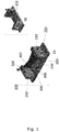
- FIG. 2 shows a pre-fabricated water control sluice gate system with one sluice gate member (flap gate) 400 in accordance with various embodiments of the invention.
- Figure 2A shows the sluice gate member 400 in a closed position
- a Figure 2B shows the sluice gate member in an open position
- the pre-cast reinforced concrete base panel is configured as a lower gate member 222 extending between the two side panels.
- the lower gate member 222 is positioned behind the sluice gate member to support the latter, but also to elevate the water flow away from the dirt/foundation below the base panel. The water close to the dirt/foundation below the base panel will thus be stagnant.
- the lower gate member 222 comprises water/air channels 224 adapted to be connected to a source of water and/or compressed air. Water and/or compressed air may thereby be used to remove sediments blocking the function of the one or more sluice gate members.
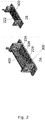
- Figure 3 shows a pre-fabricated water control sluice gate system with one sluice gate member (vertical rising gate) in accordance with various embodiments of the invention.
- Figures 3A (perspective view) and 3B (cross-sectional view) show the sluice gate member 400 in an open position
- Figure 3C (cross-sectional view) shows the sluice gate member in a closed position.
- the pre-cast reinforced concrete base panel 220 is configured as a lower gate member 222 extending between the two side panels.
- the lower gate member 222 is positioned in front of the sluice gate member to elevate the water flow away from the dirt/foundation below the base panel. The water close to the dirt/foundation below the base panel will thus be stagnant.
- the lower gate member 222 may comprise (not shown) water/air channels adapted to be connected to a source of water and/or compressed air. The water/air channel outlets may be positioned on either side of the lower gate member 222.
- the inner side/face 212 of the side panels each comprise a channel 214 configured for receiving a moving gate member 400.
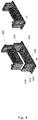
- Figure 4 shows a casing 600 adapted for receiving the pre-cast reinforced concrete frame 200 in accordance with various embodiments of the invention.
- Figure 4A shows the pre-cast reinforced concrete frame 200 about to be inserted into the casing 600
- Figure 4B shows the pre-cast reinforced concrete frame inserted into the casing.
- the casing 600 comprises two side panels 610 and a base panel 620.
- the base panel 620 is adapted for supporting the base panel 220 of the pre-cast reinforced concrete frame 200, and each side panel 610 is adapted for supporting a side panel 210 of the pre-cast reinforced concrete frame 200.
- the reinforcement 630 extends beyond the side panels 610 of the casing 600, here shown beyond the front, back and outer face of the side panel. This will allow the pre-fabricated sluice gate system to be built into other reinforced concrete structures.
- the outer face of the side panels each comprise a channel 640 configured for receiving a reinforcement plate adapted for being imbedded in the adjacent dam section.
Landscapes
- Engineering & Computer Science (AREA)
- Structural Engineering (AREA)
- General Engineering & Computer Science (AREA)
- Mechanical Engineering (AREA)
- Civil Engineering (AREA)
- Ocean & Marine Engineering (AREA)
- Barrages (AREA)
Abstract
Description
- The present invention relates to sluice gates.
- Sluice gates are used selectively to control water flow from one area of a channel to another by opening or closing off the channel to the water flow.
- The frame/foundation of the sluice gate is cast directly at the application site of the sluice gate. The flow of water must be discontinued over the portion of land, where the sluice gate is to be placed, requiring many man hours of preparation before the actual casting process can be initiated. Furthermore, the construction time is long, as the cement needs to settle and harden before a sluice gate member can be installed therein. The weather conditions may affect the hardening of the cement, resulting in a frame/foundation of poor quality and strength. Furthermore, the frame/foundation is susceptible to undermining of the water.
- It is therefore desirable to provide a system, which can eliminate some or all of the above problems.
- One aspect relates to a pre-fabricated water control sluice gate system comprising:
- a. a pre-cast reinforced concrete frame comprising:
- i. two pre-cast reinforced concrete side panels; and
- ii. a pre-cast reinforced concrete base panel interconnecting the two side panels;
- iii. at least one lifting anchor, such as at least two, three, or four lifting anchors, or coupler adapted, such as at least two, three, or four couplers, for receiving a lifting anchor;
- b. one or more sluice gate members; and
- c. an actuator adapted for moving the one or more sluice gate members;
- Another aspect relates to a pre-fabricated water control sluice gate system comprising:
- a. a first frame comprising:
- i. two side panels; and
- ii. a base panel interconnecting the two side panels;
- iii. at least one lifting anchor or coupler adapted for receiving a lifting anchor;
- b. one or more sluice gate members; and
- c. an actuator adapted for moving the one or more sluice gate members;
- In one or more embodiments, the first frame is a pre-cast concrete frame.
- In one or more embodiments, the first frame is a pre-cast reinforced concrete frame.
- The term "pre-cast" as used throughout this application means the opposite of cast in situ. In other words, the pre-cast reinforced concrete frame is finished as finished structures when shipped to a builder or customer, rather than being poured into temporary forms at the building site or place of use.
- As used herein, the term "reinforced concrete" refers to concrete into which reinforcement bars or fibres have been cast to carry tensile loads in order to strengthen a structure that would otherwise be brittle.
- The first frame may also be made of metal, wood, or a castable material. It is to be understood that any suitable castable material, such as cement, mortar, concrete, ceramics, thermoset plastics, and thermoplastics can be used for producing the first frame.
- In one or more embodiments, the side and/or base panels are made from a reinforced castable material.
- In one or more embodiments, the side and/or base panels are made from a reinforced castable material, and wherein the reinforcement extends beyond the side and/or base panels.
- As used herein, the term "reinforced castable material" refers to a castable material into which reinforcement bars or fibres have been cast to carry tensile loads in order to strengthen a structure that would otherwise be brittle.
- In the present context, the term "lifting anchor" should be broadly construed to encompass any such device for lifting the first frame with or without sluice gate members and actuators installed therein. Alternatively, a coupler adapted for receiving a lifting anchor is embedded in the first frame. The coupler may comprise internal or external threading, depending on the configuration of the lifting anchor.
- In one or more embodiments, the lifting anchor or coupler adapted for receiving a lifting anchor is mechanically tied into the reinforcing members embedded in the castable material, such as concrete.
- In order to avoid that water will undermine the base panel; it may be an advantage to extend the base panels beyond the side panels, preferably beyond the front, back and outer side/face of the side panel. In one or more embodiments, the base panel extends beyond the side panels.
- In one or more embodiments, the base panel extends beyond the front of the side panels.
- In one or more embodiments, the base panel extends beyond back of the side panels.
- In one or more embodiments, the base panel extends beyond the outer side/face of the side panels.
- In one or more embodiments, the base panel extends beyond the front and/or the back and/or the outer side of the side panels.
- In one or more embodiments, the part of the base panel extending beyond the side panels comprises channels adapted for receiving an earth anchor.
- In one or more embodiments, the reinforcement extends beyond the side and/or base panels.
- In one or more embodiments, the reinforcement extends beyond the side panels, preferably beyond the front and back of the side panel. This will allow the pre-fabricated sluice gate system to be built into other reinforced concrete structures.
- In one or more embodiments, the reinforcement extends beyond the front of the side panels.
- In one or more embodiments, the reinforcement extends beyond the back of the side panels.
- In one or more embodiments, the reinforcement extends beyond the outer side/face of the side panels.
- In one or more embodiments, the reinforcement extends beyond the front and/or the back and/or the outer side of the side panels.
- In one or more embodiments, a part of the base panel is configured as a lower sluice gate member extending between the two side panels. The base panel is preferably pre-cast. This configuration has the advantage, that it increases the strength of the sluice gate against high water levels. A substantial part of the water pressure is thereby withheld by the entire structure of the first frame. Furthermore, the lower gate member prevents that water flow passing through the first frame will remove the dirt/foundation below the first frame. The water flow is thereby elevated further away from the dirt/foundation below the first frame; and the water close to the dirt/foundation below the first frame will be stagnant. The lower sluice gate member may be positioned in front of the sluice gate members to shield the latter, and/or may be positioned behind the sluice gate members to support the latter. In one or more embodiments, the lower sluice gate member has a height of at least 5 cm, such as within the range of 5-100 cm, e.g. within the range of 10-95 cm, such as within the range of 15-90 cm, e.g. within the range of 20-85 cm, such as within the range of 25-80 cm, e.g. within the range of 30-75 cm, such as within the range of 35-70 cm, e.g. within the range of 40-65 cm, such as within the range of 45-60 cm, e.g. within the range of 50-55 cm.
- The lower sluice gate member may in one or more embodiments comprise air/water channels adapted to be connected to a source of water and/or compressed air. Water and/or compressed air may thereby be used to remove sediments blocking the function of the one or more gate members. Icing may also be prevented.
- In one or more embodiments, the outlet of the channels is positioned in close proximity, such as within 0-20 cm, e.g. within 1-15 cm, such as within 2-10 cm, e.g. within 3-5 cm, to the one or more gate members.
- In one or more embodiments, the base panel comprises air/water channels adapted to be connected to a source of water and/or compressed air.
- In one or more embodiments, the pre-fabricated water control sluice gate system further comprises means for delivering water and/or compressed air to the air/water channels.
- In one or more embodiments, the base panel comprises suction channels adapted to be connected to a source of suction. With or without the function of the air/water channels, the suction channels may be used to remove sediments blocking the function of the one or more gate members. Icing may also be prevented.
- In one or more embodiments, the lower sluice gate member comprises suction channels adapted to be connected to a source of suction.
- In one or more embodiments, the inlet of the suction channels is positioned in close proximity, such as within 0-20 cm, e.g. within 1-15 cm, such as within 2-10 cm, e.g. within 3-5 cm, to the one or more gate members.
- In one or more embodiments, the pre-fabricated water control sluice gate system further comprises a source of suction adapted for being connected to the suction channels.
- In one or more embodiments, the one or more sluice gate members are a flap gate, a mitre gate, a vertical rising gate, a radial sluice gate, a rising sector sluice gate, or a drum sluice gate, a sluice gate comprising a cylindrical surface, or combinations thereof.
- In one or more embodiments, the inner side of the side panels each comprise a channel configured for receiving a moving gate member.
- In one or more embodiments, the outer face of the side panels each comprise a channel configured for receiving a reinforcement plate adapted for being imbedded in the adjacent dam section.
- In one or more embodiments, the pre-fabricated water control sluice gate system further comprises a casing adapted for receiving the first frame, the casing comprising two side panels and a base panel, wherein the base panel is adapted for supporting the base panel of the first frame, and wherein each side panel is adapted for supporting a side panel of the first frame. This allows for a system, where the first frame may be exchanged with a spare first frame during service. Furthermore, it may be an advantage to be able to reverse the operating direction of the sluice gate by turning it 180 degrees.
- In one or more embodiments, the pre-fabricated water control sluice gate system further comprises a casing adapted for receiving the pre-cast reinforced concrete frame, the casing comprising two side panels and a base panel, wherein the base panel is adapted for supporting the base panel of the pre-cast reinforced concrete frame, and wherein each side panel is adapted for supporting a side panel of the pre-cast reinforced concrete frame. This allows for a system, where the pre-cast reinforced concrete frame may be exchanged with a spare pre-cast reinforced concrete frame during service. Furthermore, it may be an advantage to be able to reverse the operating direction of the sluice gate by turning it 180 degrees.
- In one or more embodiments, the casing comprises an opening between its side panels, such that water can flow to and from a sluice gate positioned within the casing.
- In one or more embodiments, the casing comprises an opening between its side panels, such that water can flow to and from a first frame, such as a pre-cast reinforced concrete frame, according to the present invention positioned within the casing.
- In one or more embodiments, the casing comprises a front panel with an opening, and wherein the opening is adapted such that water can flow to a sluice gate positioned within the casing; and wherein the casing further comprises a back panel with an opening, and wherein the opening is adapted such that water can flow from a sluice gate positioned within the casing.
- In one or more embodiments, the casing comprises a front panel with an opening, and wherein the opening is adapted such that water can flow to a sluice gate positioned within the casing.
- In one or more embodiments, the casing comprises a back panel with an opening, and wherein the opening is adapted such that water can flow from a sluice gate positioned within the casing.
- In one or more embodiments, the casing is made of reinforced concrete. In one or more embodiments, the casing is pre-cast.
- In one or more embodiments, the casing comprises at least one lifting anchor or coupler adapted for receiving a lifting anchor, preferably one or more pairs of lifting anchors or couplers adapted for receiving a lifting anchor to provide a stable lift.
- In order to avoid that water will undermine the base panel; it may be an advantage to extend the base panels beyond the side panels, preferably beyond the front, back and outer side/face of the side panel. In one or more embodiments, the base panel extends beyond the side panels.
- In one or more embodiments, the base panel of the casing extends beyond the front of the side panels.
- In one or more embodiments, the base panel of the casing extends beyond back of the side panels.
- In one or more embodiments, the base panel of the casing extends beyond the outer side/face of the side panels.
- In one or more embodiments, the base panel of the casing extends beyond the front and/or the back and/or the outer side of the side panels.
- In one or more embodiments, the part of the base panel of the casing extending beyond the side panels comprises channels adapted for receiving an earth anchor.
- In one or more embodiments, the reinforcement extends beyond the side panels of the casing, preferably beyond the front and back of the side panel. This will allow the pre-fabricated sluice gate system to be built into other reinforced concrete structures.
- In one or more embodiments, the reinforcement extends beyond the front of the side panels of the casing.
- In one or more embodiments, the reinforcement extends beyond the back of the side panels of the casing.
- In one or more embodiments, the reinforcement extends beyond the outer side/face of the side panels of the casing.
- In one or more embodiments, the reinforcement extends beyond the front and/or the back and/or the outer side of the side panels of the casing.
- In one or more embodiments, the outer face of the side panels each comprise a channel configured for receiving a reinforcement plate adapted for being imbedded in the adjacent dam section.
- A second aspect relates to a pre-cast reinforced concrete frame for a water control sluice gate system comprising:
- i. two pre-cast reinforced concrete side panels; and
- ii. a pre-cast reinforced concrete base panel interconnecting the two side panels;
- iii. at least one lifting anchor or coupler adapted for receiving a lifting anchor;
- A third aspect relates to a first frame for a water control sluice gate system comprising:
- i. two side panels; and
- ii. a base panel interconnecting the two side panels;
- iii. at least one lifting anchor or coupler adapted for receiving a lifting anchor;
- In one or more embodiments, the base panel extends beyond the side panels, and wherein the part of the base panel extending beyond the side panels comprises channels adapted for receiving an earth anchor.
- In one or more embodiments, the outer face of the side panels each comprise a channel configured for receiving a reinforcement plate adapted for being imbedded in the adjacent dam section.
- A fourth aspect relates to a method for segregating a body of water into two distinct parts with a pre-fabricated water control sluice gate system comprising the steps of:
- sinking a pre-fabricated sluice gate system according to the present invention at a predetermined location in the body of water, the pre-cast reinforced concrete side panels of the pre-cast reinforced concrete frame having been chosen so as to have sufficient height to protrude above the water level of the body of water after the sluice gate system is sunk at its predetermined location; and
- building a dam up against the outer face of the side panels. This method has a particular advantage over existing methods in that no preliminary dam has to be built, and water pumped out of the area, to secure the location on which the water control sluice gate system is to be build/cast.
- A fifth aspect relates to a method for segregating a body of water into two distinct parts with a pre-fabricated water control sluice gate system comprising the steps of:
- sinking a pre-fabricated sluice gate system according to according to the present invention at a predetermined location in the body of water, the side panels of the first frame having been chosen so as to have sufficient height to protrude above the water level of the body of water after the sluice gate system is sunk at its predetermined location; and
- building a dam up against the outer face of the side panels.
- It should be noted that embodiments and features described in the context of one of the aspects of the present invention also apply to the other aspects of the invention.
-
-
Figure 1 shows a pre-fabricated water control sluice gate system with two sluice gate members (mitre gate) in accordance with various embodiments of the invention; -
Figure 2 shows a pre-fabricated water control sluice gate system with one sluice gate member (flap gate) in accordance with various embodiments of the invention; -
Figure 3 shows a pre-fabricated water control sluice gate system with one sluice gate member (vertical rising gate) in accordance with various embodiments of the invention; and -
Figure 4 shows a casing adapted for receiving the first frame, such as a pre-cast reinforced concrete frame, in accordance with various embodiments of the invention. - The following pre-fabricated water control sluice gate systems are constructed of reinforced concrete, but could also be constructed of other materials.
-
Figure 1 shows a pre-fabricated water control sluice gate system with two sluice gate members (mitre gate) in accordance with various embodiments of the invention.Figure 1A shows thesluice gate member 400 in a closed position, and aFigure 1B shows the sluice gate member in an open position. The pre-fabricated water controlsluice gate system 100 comprises a pre-cast reinforcedconcrete frame 200, liftinganchors 300, twosluice gate members 400, and anactuator 500 adapted for moving thesluice gate members 400. - The pre-cast reinforced
concrete frame 200 comprises two pre-cast reinforcedconcrete side panels 210, and a pre-cast reinforcedconcrete base panel 220 interconnecting the twoside panels 210. Theside base panel 220 is adapted for mounting thesluice gate members 400 thereto. - The
base panel 220 is shown extending beyond the outer side/face of theside panels 210. Large stones may be placed on this part to keep the pre-cast reinforcedconcrete frame 200 in place. - A part of the
base panel 220 is configured as alower gate member 222 extending between the twoside panels 210. Thelower gate member 222 is positioned behind thesluice gate members 400 to support the latter. -
Figure 2 shows a pre-fabricated water control sluice gate system with one sluice gate member (flap gate) 400 in accordance with various embodiments of the invention. -
Figure 2A shows thesluice gate member 400 in a closed position, and aFigure 2B shows the sluice gate member in an open position. - The pre-cast reinforced concrete base panel is configured as a
lower gate member 222 extending between the two side panels. Thelower gate member 222 is positioned behind the sluice gate member to support the latter, but also to elevate the water flow away from the dirt/foundation below the base panel. The water close to the dirt/foundation below the base panel will thus be stagnant. Thelower gate member 222 comprises water/air channels 224 adapted to be connected to a source of water and/or compressed air. Water and/or compressed air may thereby be used to remove sediments blocking the function of the one or more sluice gate members. -
Figure 3 shows a pre-fabricated water control sluice gate system with one sluice gate member (vertical rising gate) in accordance with various embodiments of the invention.Figures 3A (perspective view) and 3B (cross-sectional view) show thesluice gate member 400 in an open position, whileFigure 3C (cross-sectional view) shows the sluice gate member in a closed position. - The pre-cast reinforced
concrete base panel 220 is configured as alower gate member 222 extending between the two side panels. Thelower gate member 222 is positioned in front of the sluice gate member to elevate the water flow away from the dirt/foundation below the base panel. The water close to the dirt/foundation below the base panel will thus be stagnant. Thelower gate member 222 may comprise (not shown) water/air channels adapted to be connected to a source of water and/or compressed air. The water/air channel outlets may be positioned on either side of thelower gate member 222. - The inner side/
face 212 of the side panels each comprise achannel 214 configured for receiving a movinggate member 400. -
Figure 4 shows acasing 600 adapted for receiving the pre-cast reinforcedconcrete frame 200 in accordance with various embodiments of the invention.Figure 4A shows the pre-cast reinforcedconcrete frame 200 about to be inserted into thecasing 600, andFigure 4B shows the pre-cast reinforced concrete frame inserted into the casing. - The
casing 600 comprises twoside panels 610 and abase panel 620. Thebase panel 620 is adapted for supporting thebase panel 220 of the pre-cast reinforcedconcrete frame 200, and eachside panel 610 is adapted for supporting aside panel 210 of the pre-cast reinforcedconcrete frame 200. - The
reinforcement 630 extends beyond theside panels 610 of thecasing 600, here shown beyond the front, back and outer face of the side panel. This will allow the pre-fabricated sluice gate system to be built into other reinforced concrete structures. - The outer face of the side panels each comprise a
channel 640 configured for receiving a reinforcement plate adapted for being imbedded in the adjacent dam section. -
- 100
- Pre-fabricated water control sluice gate system
- 200
- Pre-cast reinforced concrete frame
- 210
- Side panel
- 212
- Inner side/face of the side panel
- 214
- Channel
- 220
- Base panel
- 222
- Lower gate member
- 300
- Lifting anchor
- 400
- Gate member
- 500
- Actuator
- 600
- Casing
- 610
- Side panel
- 620
- Base panel
- 630
- Reinforcement
- 640
- Channel
Claims (14)
- A pre-fabricated water control sluice gate system (100) comprising:a. a first frame (200) comprising:i. two side panels (210); andii. a base panel (220) interconnecting the two side panels (210);iii. at least one lifting anchor (300) or coupler adapted for receiving a lifting anchor;b. one or more sluice gate members (400); andc. an actuator (500) adapted for moving the one or more gate members;wherein the side (210) and/or base (220) panels are adapted for mounting the one or more gate sluice members (400) thereto.
- A pre-fabricated sluice gate system (100) according to claim 1, wherein the base panel comprises channels (224) adapted to be connected to a source of water and/or compressed air.
- A pre-fabricated sluice gate system (100) according to claim 2, wherein the outlet of the channels is positioned in close proximity to the one or more gate members (400).
- A pre-fabricated sluice gate system (100) according to any one of the claims 1-3, wherein the base panel comprises channels adapted to be connected to suction means.
- A pre-fabricated sluice gate system (100) according to claim 5, wherein the inlet of the channels is positioned in close proximity to the one or more gate members (400).
- A pre-fabricated sluice gate system (100) according to any one of the claims 1-5, wherein a part of the base panel (220) is configured as a lower gate member (222) extending between the two side panels (210).
- A pre-fabricated sluice gate system (100) according to claim 6, wherein the lower gate member comprises channels (224) adapted to be connected to a source of water and/or compressed air.
- A pre-fabricated sluice gate system (100) according to claim 7, wherein the outlet of the channels (224) is positioned in close proximity to the one or more gate members (400).
- A pre-fabricated sluice gate system (100) according to any one of the claims 1-8, wherein the base panel (220) extends beyond the side panels (210).
- A pre-fabricated sluice gate system (100) according to claim 9, wherein the part of the base panel (220) extending beyond the side panels (210) comprises channels adapted for receiving an earth anchor.
- A pre-fabricated sluice gate system (100) according to any one of the claims 1-10, wherein the side (210) and/or base (220) panels are made from a reinforced castable material, and wherein the reinforcement extends beyond the side (210) and/or base (220) panels.
- A pre-fabricated sluice gate system (100) according to any one of the claims 1-11, wherein the inner side/face (212) of the side panels each comprise a channel (214) configured for receiving a moving gate member (400).
- A pre-fabricated sluice gate system according to any one of the claims 1-12, further comprising a casing (600) adapted for receiving the first frame, the casing comprising two side panels (610) and a base panel (620), wherein the base panel (620) is adapted for supporting the base panel (220) of the first frame (200), and wherein each side panel (610) is adapted for supporting a side panel (210) of the first frame (200).
- A method for segregating a body of water into two distinct parts with a pre-fabricated water control sluice gate system comprising the steps of:- sinking a pre-fabricated sluice gate system according to any one of the claims 1-13 at a predetermined location in the body of water, the side panels of the first frame having been chosen so as to have sufficient height to protrude above the water level of the body of water after the sluice gate system is sunk at its predetermined location; and- building a dam up against the outer face of the side panels.
Applications Claiming Priority (2)
| Application Number | Priority Date | Filing Date | Title |
|---|---|---|---|
| DKPA201600057 | 2016-01-28 | ||
| DKPA201600176A DK179455B1 (en) | 2016-03-22 | 2016-03-22 | A prefabricated water control sluice system and a method of segregating a body of water with a prefabricated water control sluice system |
Publications (2)
| Publication Number | Publication Date |
|---|---|
| EP3199706A1 true EP3199706A1 (en) | 2017-08-02 |
| EP3199706B1 EP3199706B1 (en) | 2020-04-01 |
Family
ID=57838275
Family Applications (1)
| Application Number | Title | Priority Date | Filing Date |
|---|---|---|---|
| EP17151959.8A Active EP3199706B1 (en) | 2016-01-28 | 2017-01-18 | Pre-fabricated water control sluice gate system |
Country Status (1)
| Country | Link |
|---|---|
| EP (1) | EP3199706B1 (en) |
Cited By (1)
| Publication number | Priority date | Publication date | Assignee | Title |
|---|---|---|---|---|
| EP4012104A1 (en) | 2020-12-14 | 2022-06-15 | Wintec Holding ApS | Prefabricated water control system |
Citations (6)
| Publication number | Priority date | Publication date | Assignee | Title |
|---|---|---|---|---|
| GB945728A (en) * | 1962-06-22 | 1964-01-08 | Drysdale & Co Ltd | Improvements in or relating to gates for dry docks |
| DE2838431B1 (en) * | 1978-09-02 | 1979-09-20 | Meerestech Seebau Ing Ims | Folding gate to block rivers, canals, docks, etc. |
| JPS5938409A (en) * | 1982-08-24 | 1984-03-02 | Ishikawajima Constr Material Co Ltd | Concrete sluice |
| BE1004982A5 (en) * | 1991-06-20 | 1993-03-09 | Frankignoul Pieux Armes | Process for constructing a dam or dyke structure and structure obtainedusing this process |
| NL1037027C2 (en) * | 2009-06-09 | 2010-12-13 | Jan Joost Schager | LOCK AND / OR BRIDGE HEAD AS CASCO. |
| WO2014158876A1 (en) * | 2013-03-14 | 2014-10-02 | French Development Enterprises, LLC | Intelligent hydroelectric dam with power storage |
-
2017
- 2017-01-18 EP EP17151959.8A patent/EP3199706B1/en active Active
Patent Citations (6)
| Publication number | Priority date | Publication date | Assignee | Title |
|---|---|---|---|---|
| GB945728A (en) * | 1962-06-22 | 1964-01-08 | Drysdale & Co Ltd | Improvements in or relating to gates for dry docks |
| DE2838431B1 (en) * | 1978-09-02 | 1979-09-20 | Meerestech Seebau Ing Ims | Folding gate to block rivers, canals, docks, etc. |
| JPS5938409A (en) * | 1982-08-24 | 1984-03-02 | Ishikawajima Constr Material Co Ltd | Concrete sluice |
| BE1004982A5 (en) * | 1991-06-20 | 1993-03-09 | Frankignoul Pieux Armes | Process for constructing a dam or dyke structure and structure obtainedusing this process |
| NL1037027C2 (en) * | 2009-06-09 | 2010-12-13 | Jan Joost Schager | LOCK AND / OR BRIDGE HEAD AS CASCO. |
| WO2014158876A1 (en) * | 2013-03-14 | 2014-10-02 | French Development Enterprises, LLC | Intelligent hydroelectric dam with power storage |
Cited By (1)
| Publication number | Priority date | Publication date | Assignee | Title |
|---|---|---|---|---|
| EP4012104A1 (en) | 2020-12-14 | 2022-06-15 | Wintec Holding ApS | Prefabricated water control system |
Also Published As
| Publication number | Publication date |
|---|---|
| EP3199706B1 (en) | 2020-04-01 |
Similar Documents
| Publication | Publication Date | Title |
|---|---|---|
| CA2842249A1 (en) | Prefabricated reinforced concrete wall panel and installation method | |
| CN108396711A (en) | A kind of detachable gravity dam and its construction, method for dismounting | |
| EP3336260A1 (en) | Construction method of a tower foundation | |
| EP3199706B1 (en) | Pre-fabricated water control sluice gate system | |
| EP3228753B1 (en) | Modular pre-fabricated water control pump system | |
| KR101526461B1 (en) | Functional precast concrete culvert | |
| US20120005976A1 (en) | Modular foundation system and method | |
| CN106930391B (en) | Cast-in-place drainage channel structure of top plate for formwork-free construction and construction method | |
| EP3486376B1 (en) | Pre-fabricated water control sluice gate system with anti-sedimentation function | |
| DK201600176A1 (en) | Pre-fabricated water control sluice gate system and a first frame therefore | |
| CN107268617A (en) | Construction technology and device after a kind of anti-float anchor rod | |
| EP4012104A1 (en) | Prefabricated water control system | |
| CN108343452A (en) | A kind of sand gravel tunnel rockfill grouting construction | |
| CN109826441B (en) | Lateral pre-embedding installation method for C-shaped hafen groove of concrete structure | |
| KR102105771B1 (en) | Water proofing plate installed with forms | |
| KR102026112B1 (en) | Pre-cast concrete segment blocks for vertical structures with various bracket connection means | |
| DK201700071Y3 (en) | Prefabricated water control sluice gate system and a first frame thereto | |
| CN205242695U (en) | Take superimposed shear wall of keyway that shears | |
| JPH09151470A (en) | Work execution method for underground structure | |
| DK202000132U3 (en) | Prefabricated water management system | |
| JP2020041286A (en) | Method of renovating circular water conduit | |
| CN218813822U (en) | Hydrophobic drainage device of bottom plate construction and hydrophobic well structure | |
| KR100854578B1 (en) | The method of presetting-up the pile-mixed wall | |
| CN211900640U (en) | Door-shaped corrugated steel reinforcing structure | |
| KR200417545Y1 (en) | Half assembly-typed construction system of common duct |
Legal Events
| Date | Code | Title | Description |
|---|---|---|---|
| PUAI | Public reference made under article 153(3) epc to a published international application that has entered the european phase |
Free format text: ORIGINAL CODE: 0009012 |
|
| STAA | Information on the status of an ep patent application or granted ep patent |
Free format text: STATUS: THE APPLICATION HAS BEEN PUBLISHED |
|
| AK | Designated contracting states |
Kind code of ref document: A1 Designated state(s): AL AT BE BG CH CY CZ DE DK EE ES FI FR GB GR HR HU IE IS IT LI LT LU LV MC MK MT NL NO PL PT RO RS SE SI SK SM TR |
|
| AX | Request for extension of the european patent |
Extension state: BA ME |
|
| STAA | Information on the status of an ep patent application or granted ep patent |
Free format text: STATUS: REQUEST FOR EXAMINATION WAS MADE |
|
| 17P | Request for examination filed |
Effective date: 20180202 |
|
| RBV | Designated contracting states (corrected) |
Designated state(s): AL AT BE BG CH CY CZ DE DK EE ES FI FR GB GR HR HU IE IS IT LI LT LU LV MC MK MT NL NO PL PT RO RS SE SI SK SM TR |
|
| GRAP | Despatch of communication of intention to grant a patent |
Free format text: ORIGINAL CODE: EPIDOSNIGR1 |
|
| STAA | Information on the status of an ep patent application or granted ep patent |
Free format text: STATUS: GRANT OF PATENT IS INTENDED |
|
| INTG | Intention to grant announced |
Effective date: 20200114 |
|
| GRAS | Grant fee paid |
Free format text: ORIGINAL CODE: EPIDOSNIGR3 |
|
| GRAA | (expected) grant |
Free format text: ORIGINAL CODE: 0009210 |
|
| STAA | Information on the status of an ep patent application or granted ep patent |
Free format text: STATUS: THE PATENT HAS BEEN GRANTED |
|
| AK | Designated contracting states |
Kind code of ref document: B1 Designated state(s): AL AT BE BG CH CY CZ DE DK EE ES FI FR GB GR HR HU IE IS IT LI LT LU LV MC MK MT NL NO PL PT RO RS SE SI SK SM TR |
|
| REG | Reference to a national code |
Ref country code: GB Ref legal event code: FG4D |
|
| REG | Reference to a national code |
Ref country code: AT Ref legal event code: REF Ref document number: 1251474 Country of ref document: AT Kind code of ref document: T Effective date: 20200415 Ref country code: CH Ref legal event code: EP |
|
| REG | Reference to a national code |
Ref country code: DE Ref legal event code: R096 Ref document number: 602017013789 Country of ref document: DE |
|
| REG | Reference to a national code |
Ref country code: IE Ref legal event code: FG4D |
|
| PG25 | Lapsed in a contracting state [announced via postgrant information from national office to epo] |
Ref country code: BG Free format text: LAPSE BECAUSE OF FAILURE TO SUBMIT A TRANSLATION OF THE DESCRIPTION OR TO PAY THE FEE WITHIN THE PRESCRIBED TIME-LIMIT Effective date: 20200701 |
|
| REG | Reference to a national code |
Ref country code: NL Ref legal event code: MP Effective date: 20200401 |
|
| REG | Reference to a national code |
Ref country code: LT Ref legal event code: MG4D |
|
| PG25 | Lapsed in a contracting state [announced via postgrant information from national office to epo] |
Ref country code: LT Free format text: LAPSE BECAUSE OF FAILURE TO SUBMIT A TRANSLATION OF THE DESCRIPTION OR TO PAY THE FEE WITHIN THE PRESCRIBED TIME-LIMIT Effective date: 20200401 Ref country code: CZ Free format text: LAPSE BECAUSE OF FAILURE TO SUBMIT A TRANSLATION OF THE DESCRIPTION OR TO PAY THE FEE WITHIN THE PRESCRIBED TIME-LIMIT Effective date: 20200401 Ref country code: NL Free format text: LAPSE BECAUSE OF FAILURE TO SUBMIT A TRANSLATION OF THE DESCRIPTION OR TO PAY THE FEE WITHIN THE PRESCRIBED TIME-LIMIT Effective date: 20200401 Ref country code: FI Free format text: LAPSE BECAUSE OF FAILURE TO SUBMIT A TRANSLATION OF THE DESCRIPTION OR TO PAY THE FEE WITHIN THE PRESCRIBED TIME-LIMIT Effective date: 20200401 Ref country code: IS Free format text: LAPSE BECAUSE OF FAILURE TO SUBMIT A TRANSLATION OF THE DESCRIPTION OR TO PAY THE FEE WITHIN THE PRESCRIBED TIME-LIMIT Effective date: 20200801 Ref country code: SE Free format text: LAPSE BECAUSE OF FAILURE TO SUBMIT A TRANSLATION OF THE DESCRIPTION OR TO PAY THE FEE WITHIN THE PRESCRIBED TIME-LIMIT Effective date: 20200401 Ref country code: GR Free format text: LAPSE BECAUSE OF FAILURE TO SUBMIT A TRANSLATION OF THE DESCRIPTION OR TO PAY THE FEE WITHIN THE PRESCRIBED TIME-LIMIT Effective date: 20200702 Ref country code: NO Free format text: LAPSE BECAUSE OF FAILURE TO SUBMIT A TRANSLATION OF THE DESCRIPTION OR TO PAY THE FEE WITHIN THE PRESCRIBED TIME-LIMIT Effective date: 20200701 Ref country code: PT Free format text: LAPSE BECAUSE OF FAILURE TO SUBMIT A TRANSLATION OF THE DESCRIPTION OR TO PAY THE FEE WITHIN THE PRESCRIBED TIME-LIMIT Effective date: 20200817 |
|
| REG | Reference to a national code |
Ref country code: AT Ref legal event code: MK05 Ref document number: 1251474 Country of ref document: AT Kind code of ref document: T Effective date: 20200401 |
|
| PG25 | Lapsed in a contracting state [announced via postgrant information from national office to epo] |
Ref country code: LV Free format text: LAPSE BECAUSE OF FAILURE TO SUBMIT A TRANSLATION OF THE DESCRIPTION OR TO PAY THE FEE WITHIN THE PRESCRIBED TIME-LIMIT Effective date: 20200401 Ref country code: HR Free format text: LAPSE BECAUSE OF FAILURE TO SUBMIT A TRANSLATION OF THE DESCRIPTION OR TO PAY THE FEE WITHIN THE PRESCRIBED TIME-LIMIT Effective date: 20200401 Ref country code: RS Free format text: LAPSE BECAUSE OF FAILURE TO SUBMIT A TRANSLATION OF THE DESCRIPTION OR TO PAY THE FEE WITHIN THE PRESCRIBED TIME-LIMIT Effective date: 20200401 |
|
| PG25 | Lapsed in a contracting state [announced via postgrant information from national office to epo] |
Ref country code: AL Free format text: LAPSE BECAUSE OF FAILURE TO SUBMIT A TRANSLATION OF THE DESCRIPTION OR TO PAY THE FEE WITHIN THE PRESCRIBED TIME-LIMIT Effective date: 20200401 |
|
| REG | Reference to a national code |
Ref country code: DE Ref legal event code: R097 Ref document number: 602017013789 Country of ref document: DE |
|
| PG25 | Lapsed in a contracting state [announced via postgrant information from national office to epo] |
Ref country code: ES Free format text: LAPSE BECAUSE OF FAILURE TO SUBMIT A TRANSLATION OF THE DESCRIPTION OR TO PAY THE FEE WITHIN THE PRESCRIBED TIME-LIMIT Effective date: 20200401 Ref country code: RO Free format text: LAPSE BECAUSE OF FAILURE TO SUBMIT A TRANSLATION OF THE DESCRIPTION OR TO PAY THE FEE WITHIN THE PRESCRIBED TIME-LIMIT Effective date: 20200401 Ref country code: SM Free format text: LAPSE BECAUSE OF FAILURE TO SUBMIT A TRANSLATION OF THE DESCRIPTION OR TO PAY THE FEE WITHIN THE PRESCRIBED TIME-LIMIT Effective date: 20200401 Ref country code: EE Free format text: LAPSE BECAUSE OF FAILURE TO SUBMIT A TRANSLATION OF THE DESCRIPTION OR TO PAY THE FEE WITHIN THE PRESCRIBED TIME-LIMIT Effective date: 20200401 Ref country code: DK Free format text: LAPSE BECAUSE OF FAILURE TO SUBMIT A TRANSLATION OF THE DESCRIPTION OR TO PAY THE FEE WITHIN THE PRESCRIBED TIME-LIMIT Effective date: 20200401 Ref country code: AT Free format text: LAPSE BECAUSE OF FAILURE TO SUBMIT A TRANSLATION OF THE DESCRIPTION OR TO PAY THE FEE WITHIN THE PRESCRIBED TIME-LIMIT Effective date: 20200401 Ref country code: IT Free format text: LAPSE BECAUSE OF FAILURE TO SUBMIT A TRANSLATION OF THE DESCRIPTION OR TO PAY THE FEE WITHIN THE PRESCRIBED TIME-LIMIT Effective date: 20200401 |
|
| PLBE | No opposition filed within time limit |
Free format text: ORIGINAL CODE: 0009261 |
|
| STAA | Information on the status of an ep patent application or granted ep patent |
Free format text: STATUS: NO OPPOSITION FILED WITHIN TIME LIMIT |
|
| PG25 | Lapsed in a contracting state [announced via postgrant information from national office to epo] |
Ref country code: PL Free format text: LAPSE BECAUSE OF FAILURE TO SUBMIT A TRANSLATION OF THE DESCRIPTION OR TO PAY THE FEE WITHIN THE PRESCRIBED TIME-LIMIT Effective date: 20200401 Ref country code: SK Free format text: LAPSE BECAUSE OF FAILURE TO SUBMIT A TRANSLATION OF THE DESCRIPTION OR TO PAY THE FEE WITHIN THE PRESCRIBED TIME-LIMIT Effective date: 20200401 |
|
| 26N | No opposition filed |
Effective date: 20210112 |
|
| PG25 | Lapsed in a contracting state [announced via postgrant information from national office to epo] |
Ref country code: SI Free format text: LAPSE BECAUSE OF FAILURE TO SUBMIT A TRANSLATION OF THE DESCRIPTION OR TO PAY THE FEE WITHIN THE PRESCRIBED TIME-LIMIT Effective date: 20200401 |
|
| PG25 | Lapsed in a contracting state [announced via postgrant information from national office to epo] |
Ref country code: MC Free format text: LAPSE BECAUSE OF FAILURE TO SUBMIT A TRANSLATION OF THE DESCRIPTION OR TO PAY THE FEE WITHIN THE PRESCRIBED TIME-LIMIT Effective date: 20200401 |
|
| REG | Reference to a national code |
Ref country code: CH Ref legal event code: PL |
|
| PG25 | Lapsed in a contracting state [announced via postgrant information from national office to epo] |
Ref country code: LU Free format text: LAPSE BECAUSE OF NON-PAYMENT OF DUE FEES Effective date: 20210118 |
|
| REG | Reference to a national code |
Ref country code: BE Ref legal event code: MM Effective date: 20210131 |
|
| PG25 | Lapsed in a contracting state [announced via postgrant information from national office to epo] |
Ref country code: CH Free format text: LAPSE BECAUSE OF NON-PAYMENT OF DUE FEES Effective date: 20210131 Ref country code: LI Free format text: LAPSE BECAUSE OF NON-PAYMENT OF DUE FEES Effective date: 20210131 |
|
| PG25 | Lapsed in a contracting state [announced via postgrant information from national office to epo] |
Ref country code: IE Free format text: LAPSE BECAUSE OF NON-PAYMENT OF DUE FEES Effective date: 20210118 |
|
| PG25 | Lapsed in a contracting state [announced via postgrant information from national office to epo] |
Ref country code: BE Free format text: LAPSE BECAUSE OF NON-PAYMENT OF DUE FEES Effective date: 20210131 |
|
| PGFP | Annual fee paid to national office [announced via postgrant information from national office to epo] |
Ref country code: FR Payment date: 20230125 Year of fee payment: 7 |
|
| PG25 | Lapsed in a contracting state [announced via postgrant information from national office to epo] |
Ref country code: HU Free format text: LAPSE BECAUSE OF FAILURE TO SUBMIT A TRANSLATION OF THE DESCRIPTION OR TO PAY THE FEE WITHIN THE PRESCRIBED TIME-LIMIT; INVALID AB INITIO Effective date: 20170118 |
|
| PG25 | Lapsed in a contracting state [announced via postgrant information from national office to epo] |
Ref country code: CY Free format text: LAPSE BECAUSE OF FAILURE TO SUBMIT A TRANSLATION OF THE DESCRIPTION OR TO PAY THE FEE WITHIN THE PRESCRIBED TIME-LIMIT Effective date: 20200401 |
|
| PG25 | Lapsed in a contracting state [announced via postgrant information from national office to epo] |
Ref country code: MK Free format text: LAPSE BECAUSE OF FAILURE TO SUBMIT A TRANSLATION OF THE DESCRIPTION OR TO PAY THE FEE WITHIN THE PRESCRIBED TIME-LIMIT Effective date: 20200401 |
|
| PGFP | Annual fee paid to national office [announced via postgrant information from national office to epo] |
Ref country code: DE Payment date: 20240129 Year of fee payment: 8 Ref country code: GB Payment date: 20240129 Year of fee payment: 8 |