EP3199481A1 - Apparatus for unwinding cables on seabeds and method of operation of an apparatus for unwinding cables on seabeds - Google Patents
Apparatus for unwinding cables on seabeds and method of operation of an apparatus for unwinding cables on seabeds Download PDFInfo
- Publication number
- EP3199481A1 EP3199481A1 EP17153569.3A EP17153569A EP3199481A1 EP 3199481 A1 EP3199481 A1 EP 3199481A1 EP 17153569 A EP17153569 A EP 17153569A EP 3199481 A1 EP3199481 A1 EP 3199481A1
- Authority
- EP
- European Patent Office
- Prior art keywords
- reel
- movable
- cable
- rotation axis
- towers
- Prior art date
- Legal status (The legal status is an assumption and is not a legal conclusion. Google has not performed a legal analysis and makes no representation as to the accuracy of the status listed.)
- Granted
Links
- 238000000034 method Methods 0.000 title claims description 25
- 230000005540 biological transmission Effects 0.000 claims abstract description 39
- 230000033001 locomotion Effects 0.000 claims description 38
- 238000001514 detection method Methods 0.000 claims description 10
- 238000005259 measurement Methods 0.000 claims description 8
- 238000012546 transfer Methods 0.000 claims description 5
- 238000011017 operating method Methods 0.000 claims 2
- 238000013519 translation Methods 0.000 claims 1
- 238000006243 chemical reaction Methods 0.000 description 11
- 238000006073 displacement reaction Methods 0.000 description 7
- 229910000831 Steel Inorganic materials 0.000 description 6
- 239000010959 steel Substances 0.000 description 6
- 230000009471 action Effects 0.000 description 4
- 230000008878 coupling Effects 0.000 description 4
- 238000010168 coupling process Methods 0.000 description 4
- 238000005859 coupling reaction Methods 0.000 description 4
- 230000007246 mechanism Effects 0.000 description 4
- 238000013459 approach Methods 0.000 description 3
- XLYOFNOQVPJJNP-UHFFFAOYSA-N water Substances O XLYOFNOQVPJJNP-UHFFFAOYSA-N 0.000 description 3
- 239000003129 oil well Substances 0.000 description 2
- 239000000126 substance Substances 0.000 description 2
- 230000004323 axial length Effects 0.000 description 1
- 230000001934 delay Effects 0.000 description 1
- 238000005286 illumination Methods 0.000 description 1
- 238000012423 maintenance Methods 0.000 description 1
- 238000004519 manufacturing process Methods 0.000 description 1
- 239000002184 metal Substances 0.000 description 1
- 239000013307 optical fiber Substances 0.000 description 1
- 230000001681 protective effect Effects 0.000 description 1
- 230000002787 reinforcement Effects 0.000 description 1
- 230000008439 repair process Effects 0.000 description 1
- 230000002459 sustained effect Effects 0.000 description 1
- 210000003954 umbilical cord Anatomy 0.000 description 1
- 238000012795 verification Methods 0.000 description 1
Images


Classifications
-
- B—PERFORMING OPERATIONS; TRANSPORTING
- B65—CONVEYING; PACKING; STORING; HANDLING THIN OR FILAMENTARY MATERIAL
- B65H—HANDLING THIN OR FILAMENTARY MATERIAL, e.g. SHEETS, WEBS, CABLES
- B65H49/00—Unwinding or paying-out filamentary material; Supporting, storing or transporting packages from which filamentary material is to be withdrawn or paid-out
- B65H49/18—Methods or apparatus in which packages rotate
- B65H49/20—Package-supporting devices
- B65H49/32—Stands or frameworks
-
- B—PERFORMING OPERATIONS; TRANSPORTING
- B63—SHIPS OR OTHER WATERBORNE VESSELS; RELATED EQUIPMENT
- B63B—SHIPS OR OTHER WATERBORNE VESSELS; EQUIPMENT FOR SHIPPING
- B63B35/00—Vessels or similar floating structures specially adapted for specific purposes and not otherwise provided for
- B63B35/04—Cable-laying vessels
-
- B—PERFORMING OPERATIONS; TRANSPORTING
- B65—CONVEYING; PACKING; STORING; HANDLING THIN OR FILAMENTARY MATERIAL
- B65H—HANDLING THIN OR FILAMENTARY MATERIAL, e.g. SHEETS, WEBS, CABLES
- B65H57/00—Guides for filamentary materials; Supports therefor
- B65H57/28—Reciprocating or oscillating guides
-
- B—PERFORMING OPERATIONS; TRANSPORTING
- B65—CONVEYING; PACKING; STORING; HANDLING THIN OR FILAMENTARY MATERIAL
- B65H—HANDLING THIN OR FILAMENTARY MATERIAL, e.g. SHEETS, WEBS, CABLES
- B65H67/00—Replacing or removing cores, receptacles, or completed packages at paying-out, winding, or depositing stations
- B65H67/02—Arrangements for removing spent cores or receptacles and replacing by supply packages at paying-out stations
-
- H—ELECTRICITY
- H02—GENERATION; CONVERSION OR DISTRIBUTION OF ELECTRIC POWER
- H02G—INSTALLATION OF ELECTRIC CABLES OR LINES, OR OF COMBINED OPTICAL AND ELECTRIC CABLES OR LINES
- H02G1/00—Methods or apparatus specially adapted for installing, maintaining, repairing or dismantling electric cables or lines
- H02G1/06—Methods or apparatus specially adapted for installing, maintaining, repairing or dismantling electric cables or lines for laying cables, e.g. laying apparatus on vehicle
- H02G1/10—Methods or apparatus specially adapted for installing, maintaining, repairing or dismantling electric cables or lines for laying cables, e.g. laying apparatus on vehicle in or under water
-
- B—PERFORMING OPERATIONS; TRANSPORTING
- B65—CONVEYING; PACKING; STORING; HANDLING THIN OR FILAMENTARY MATERIAL
- B65H—HANDLING THIN OR FILAMENTARY MATERIAL, e.g. SHEETS, WEBS, CABLES
- B65H2701/00—Handled material; Storage means
- B65H2701/30—Handled filamentary material
- B65H2701/34—Handled filamentary material electric cords or electric power cables
Definitions
- the present invention regards an apparatus for unwinding cables on seabeds and a method of operation of an apparatus for unwinding cables on seabeds.
- the present apparatus and the method fall within the industrial field of the production of offshore equipment and are intended to be used in the field of laying cables on beds of seas, lakes, basins, etc. More in detail, the apparatus that is the object of the present invention is intended to be mounted on ships in order to unwind reels of cables on a seabed, such as in particular flexible cables (for example an energy transmission cable, a data transmission signal cable, etc.) or cables made of yielded steel employed for example for injecting compressed air or water in an oil well.
- flexible cables for example an energy transmission cable, a data transmission signal cable, etc.
- cables made of yielded steel employed for example for injecting compressed air or water in an oil well.
- the reels of cables intended to be unwound by means of the present apparatus and method have diameter of about 6 to 24 meters and weight of about 200 to 2500 tons.
- the apparatuses for unwinding cables on seabeds such as the apparatuses of known type described in the patents EP 2743560 and GB 2046207 , conventionally comprise a support structure formed by a base (mounted for example on the deck of a ship) and by two towers which rise upward for several meters, parallel to each other, starting from the base and which together support a reel of a cable to be laid on a seabed.
- each tower is preferably obtained by means of two columns that are parallel to and counter-facing each other, between which a hub-holder group that rotatably supports the reel is slidably engaged in opposite guides.
- the reel is usually constituted by a drum around which the cable is wound, which is rotated by means of the actuation of motor means directly mounted on the hub-holder group of the apparatus.
- the apparatus also comprises at least two vertical hydraulic pistons, each of which mounted between the two columns of each tower for the lifting and lowering of the reel between a lowered loading position and a raised work position.
- Two horizontal hydraulic pistons are also provided for, mounted on the base in order to move the two towers towards or away from each other along rails, in order to allow the hub-holder group respectively to be engaged with the drum of the reel or be detached from the drum itself.
- the apparatuses of known type for unwinding cables on seabeds also comprise a further laying tower, which is laid on the deck of a ship in front of the reel supported by the two aforesaid towers at several meters distance from the reel itself.
- a transmission pulley is rotatably mounted which abuttingly receives the cable that comes from the reel, in a manner such that the cable bends around the transmission pulley and vertically descends in order to enter into a space made on the deck of the ship at the feet of the laying tower, so as to bring the cable itself onto the seabed.
- the transmission pulley is perimetrically provided with an annular seat (delimited between two projecting side walls), within which the cable section is inserted that lies on the transmission pulley itself, in a manner so as to guide the movement of the cable around the axis of the transmission pulley.
- the apparatus also comprises tensioning means, mounted on the laying tower and acting on the cable in order to keep it constantly under tension during the unwinding of the cable itself.
- cable reels have very high weight, typically many hundreds of tons, and can have very large size, for example with a radius between about 6 and 11 meters (and even up to 24 meters) and an axial length of about 5-6 meters.
- the drum of the reel (for example made of steel) has cylindrical form and is horizontally extended between two ends thereof, carrying the cable to be laid externally mounted thereon.
- each row of coils is composed of multiple coils wound around the axis of the drum and arranged next to each other from one end of the drum itself to the other.
- the rows of coils are arranged wound around each other, starting from an internal coil, wound around the surface of the drum of the reel, to an external row from which the cable exits from the reel in order to be brought towards the transmission pulley mounted on the laying tower.
- the reel is driven by the motor means to rotate, in order to unwind the cable that consequently slides towards the transmission pulley according to a laying direction orthogonal to the hub rotation axis.
- the cable then, descends vertically downward from the transmission pulley in order to enter within the space of the ship deck.
- the coils of the cable are unwound from each row, one after the other starting from the coil arranged at one of the ends of the drum of the reel up to the other end of the drum itself.
- the drum of the reel has several meters length (e.g. 5-6 meters), while the coils placed at the ends of the drum are being unwound, the section of cable that is extended from the reel to the transmission pulley forms a relatively high angle with respect to the aforesaid laying direction (orthogonal to the hub rotation axis).
- the verification of the aforesaid jamming and damage conditions requires interrupting the operations of laying and executing repair operations that are particularly long and difficult, since it is necessary to operate on the cable at high heights from the ship deck. More in detail, it is necessary to interrupt the movement of the reel, arrange suitable support frameworks in order to sustain the cable at the damaged parts, cut the cable at such damaged parts and then weld the cable itself, and operation must also occur at over ten meters height from the ship deck. Such operations require interrupting the operations of laying the cable, even for a week, with consequent delays in the completion of the work and considerable additional expenses (even hundreds of thousands of dollars) to be sustained, for example for the maintenance of the ship on which the apparatus is mounted.
- the international patent WO 2009/077711 describes an apparatus for unwinding cables on seabeds, which comprises a straightener group intended to receive the cable unwound from the reel, which is movable to slide parallel to its rotation axis in order to align the unwound cable with the aforesaid straightener group.
- the apparatus described in WO 2009/077711 does not allow ensuring optimal reliability conditions during the unwinding of the cable on the seabed.
- the problem underlying the present invention is therefore that of overcoming the drawbacks of the abovementioned prior art, by providing an apparatus for unwinding cables on seabeds and a method for operating said apparatus, which are entirely reliable in operation and, in particular, which allow unwinding the cables without the risk of damaging the latter.
- a further object of the present invention is to provide an apparatus for unwinding cables on seabeds and a method for operating said apparatus, which allow executing the laying operations in relatively quick times and with relatively limited costs.
- a further object of the present invention is to provide an apparatus for unwinding cables on seabeds, which occupies relatively limited spaces.
- a further object of the present invention is to provide an apparatus for unwinding cables on seabeds, which is structurally simple and inexpensive to make.
- reference number 1 overall indicates the apparatus for unwinding cables on seabeds, object of the present invention.
- the present apparatus 1 is intended to be advantageously employed in offshore work sites for laying cables on the seabed, e.g. of seas, lakes, water basins.
- the present apparatus 1 is employable for laying cables made of yielded steel, intended to be used for example for injecting compressed air or water into an oil well, or also for laying flexible cables intended for various applications, such as energy transmission cables, data transmission signal cables (e.g. made of optical fiber), flexible tubes and more generally flexible umbilical cords.
- the present apparatus 1 is intended to be arranged on a support platform 100 such as a deck of a ship or of a lighter or of a pontoon equipped for operating in an offshore work site.
- a support platform 100 such as a deck of a ship or of a lighter or of a pontoon equipped for operating in an offshore work site.
- Such support platform 100 is provided with a space 101 vertically extended in a through manner through the support platform itself and through which the cable to be unwound is made to descend into the sea towards the seabeds, as described in detail hereinbelow.
- the apparatus 1 comprises two movable towers 2 arranged parallel to and spaced from each other and intended to be arranged on the support platform 100.
- the two movable towers 2 are advantageously extended according to corresponding vertical extension directions X.
- the apparatus 1 comprises two hubs 3 which are arranged facing each other, are rotatably constrained to the corresponding movable towers 2 and are susceptible of being mechanically engaged with a reel 4 of the cable to be unwound.
- each hub 3 is rotatable around a first rotation axis W1, preferably horizontal and orthogonal to the first extension directions X of the two movable towers 2.
- the reel 4 is provided with a drum 5 intended to be arranged coaxially with respect to the first rotation axis W1 and with a cable 6 wound around the drum 5 itself.
- the drum 5 of the reel 4 (made for example of steel) has substantially cylindrical form and is extended according to a (preferably horizontal) longitudinal axis L thereof between a first end 7 and a second end 8, which are intended to be engaged with the corresponding hubs 3 of the apparatus 1.
- the cable 6 is constituted by an elongated element intended to be laid offshore and having a diameter (or more generally a width) comprised for example between 8 and 25 cm and a weight comprised for example between 20 and 50 kg per linear meter.
- the cable 6 of the reel 4 is wound around the drum 5, forming at least one row 9 of coils 10 arranged side-by-side each other along the first rotation axis W1 and comprising a terminal coil 10' from which the cable 6 is susceptible of being unwound from the drum 5.
- the coils 10 of each row 9 are arranged (in succession) between two end coils 10" preferably arranged in proximity to the corresponding ends 7, 8 of the drum 5.
- the cable 6 is wound around the drum 5 of the reel 4, forming multiple aforesaid rows 9 of coils 10 arranged on top of each other. More in detail, the rows 9 of coils 10 are arranged wound on each other, starting from an innermost row 9', wound around the external surface of the drum 5, to an outermost row 9" from which the cable 6 is susceptible of being unwound at the aforesaid terminal coil 10'.
- the apparatus 1 comprises movement means 11 mechanically connected to the hubs 3 and adapted to rotate the latter around the first rotation axis W1 in order to drive the reel 4 to rotate around the first rotation axis W1 itself, so as to at least unwind the cable 6 from the drum 5 at the terminal coil 10'.
- the coils 10 of the outermost row 9" are unwound one after the other starting from the terminal coil 10'.
- the next coil 10 of the outermost row 9" is unwound, which therefore becomes the new terminal coil 10'.
- the cable 6 being unwound is moved along the first rotation axis W from one end of the ends 7, 8 of the drum 5 of the reel 4 to the other, being brought to the terminal coil 10' which is unwound from the drum 5 itself.
- the movement means 11 of the apparatus 1 comprise two hub-holder groups 12, each of which mounted on the corresponding movable tower 2 and in turn carrying the corresponding hub 3 rotatably mounted thereon.
- each hub-holder group 12 comprises a support body 13, preferably metallic with box-like form, for example with parallelepiped form, which rotatably carries, mounted thereon, the corresponding hub 3 in particular having the shape of a cylindrical body peripherally provided with notches adapted to be engaged in corresponding teeth made on the internal profile of a connection flange (of type per se known to the man skilled in the art) fixed to the corresponding end 7, 8 of the drum 5 of the reel 4, in order to transmit thereto the rotation motion for unwinding the cable 6.
- a connection flange of type per se known to the man skilled in the art
- the apparatus 1 comprises a laying tower 15 intended to be fixed on the support platform 100 and transmission means 16, which are mounted on the laying tower 15 and are arranged in particular in front of two movable towers 2.
- the transmission means 16 are arranged to intercept an unwinding direction Z orthogonal to the first rotation axis W1 of the hubs 3 and passing between the movable towers 2.
- the transmission means 16 are susceptible of receiving, in engagement, a section of the cable 6 unwound from the drum 5 of the reel 4 and for transmitting such section of the cable 6 downward in order to make the latter enter into the space 101 of the support platform 100, so as to make the cable 6 itself descend into the sea towards the seabeds.
- the laying tower 15 in particular obtained by means of metallic structures, is vertically extended between a base thereof, intended to be fixed on the support platform 100 at the space 101, and a top thereof at which the transmission means 16 are mounted.
- the transmission means 16 comprise a transmission pulley 17 mounted at the top of the laying tower 15, arranged aligned with the unwinding direction Z and rotatably around a second rotation axis W2 parallel to the first rotation axis W1 of the hubs 3 and preferably horizontal.
- the transmission pulley 17 is adapted to receive, abuttingly on the upper part, the unwound cable 6 coming from the reel 4 and is drivable to rotate around the second rotation axis W2 thereof in order to guide the cable 6 towards the space 101 of the support platform 100. More in detail, the cable 6 at the transmission pulley 17 bends downward, following the curvature of the transmission pulley 17 itself so as to descend towards the space 101.
- the transmission pulley 17 is perimetrically provided with an annular seat 18 (delimited between two projecting side walls 19) within which the section of cable 6 is susceptible of being inserted, such section lying on the transmission pulley 17 itself, in a manner so as to guide the movement of the cable 6 around the second rotation axis W2 of the transmission pulley 17.
- the apparatus 1 also comprises tensioning means, mounted on the laying tower 15, operating on the cable 6 in order to keep it constantly taut during the unwinding of the cable 6 itself.
- tensioning means are of type per se known to the man skilled in the art and therefore will not be described in detail hereinbelow.
- the apparatus 1 comprises a transverse track 20, which is intended to be arranged on the support platform 100 and carries, slidably constrained thereto, the movable towers 2.
- the transverse track 20 is extended, between a first side thereof of end 21 and a second side thereof of end 22, according to a moving direction T parallel to the first rotation axis W1 of the hubs 3 and preferably rectilinear and horizontal.
- the reel 4 is intended to be engaged between the two movable towers 2 arranged with the first and the second end 7, 8 of the drum 5 respectively directed towards the first and the second end side 21, 22 of the transverse track 20.
- the apparatus 1 also comprises moving means 23 mechanically connected to the movable towers 2 and adapted to move the latter along the transverse track 20 according to the moving direction T.
- the moving means 23 are arranged for simultaneously moving the two movable towers 2 in a same direction as the aforesaid moving direction T in order to maintain the terminal coil 10' of the reel 4 aligned with the transmission means 16 (according to the unwinding direction Z) during the unwinding of the cable 6 from the reel 4 itself
- the moving means 23 are arranged for moving the two movable towers to selectively slide together in a first direction V1 of the moving direction T (in order to move the movable towers 2 towards the first end side 21 of the transverse track 20) or in a second direction V2 of the moving direction T (in order to move the movable towers 2 towards the second end side 22 of the transverse track 20).
- the apparatus 1 comprises position identification means (not illustrated in the enclosed figures) arranged for determining a position parameter indicative of the position, along the first rotation axis W1, of the terminal coil 10' of the cable 6 of the reel 4, and control means (also not illustrated in the enclosed figures) operatively connected to the position identification means and to the moving means 23 and arranged for commanding, as a function of the aforesaid position parameter, the moving means 23 to move the movable towers 2 along the moving direction T in order to maintain the terminal coil 10' of the reel 4 substantially aligned with the aforesaid unwinding direction Z.
- position identification means not illustrated in the enclosed figures
- control means also not illustrated in the enclosed figures
- the cable 6, at the terminal coil 10' is arranged within a deviation interval (parallel to the first rotation axis W1) centered on the unwinding direction Z and extended from both sides of the unwinding direction Z itself for a length equal to about three times the diameter of the cable 6 or, preferably, about equal to the diameter of the cable 6 itself.
- the aforesaid characteristics of the present invention allow, during the operation of the apparatus 1, maintaining the section of cable 6, which is unwound from the reel 4 and which is extended between the reel 4 itself and the transmission means 16, substantially aligned with the unwinding direction Z.
- the cable 6 is substantially parallel to the annular seat 18 of the transmission pulley 17, preventing the cable 6 itself from being damaged by rubbing against the edges of the projecting side walls 19 of the transmission pulley 17.
- the moving means 23 (adapted to move the movable towers 2 along the transverse track 20) comprise a movable platform 24 which is slidably mounted on the transverse track 20 and carries the movable towers 2 mounted in abutment thereon, and at least one actuator device 25 mechanically connected to the movable platform 24 and arranged for moving the latter to slide along the transverse track 20.
- the transverse track 20 comprises a first metallic framework, which is in particular provided with multiple first longitudinal bars 26 parallel to the moving direction T of the transverse track 20 itself and preferably connected together by one or more first transverse bars 27.
- the movable platform 24 comprises a second metallic framework in particular provided with second longitudinal bars 28 parallel to the moving direction T of the transverse track 20 and preferably connected together by second transverse bars 29.
- the moving means 23 comprise multiple aforesaid actuator devices 25 (e.g. four), of which in particular at least one of such actuator devices 25 (e.g. two) is placed at the first end side 21 of the transverse track 20, and at least another of such actuator devices 25 (e.g. two) is placed at the second end side 22 of the transverse track 20 itself (in accordance with the embodiments illustrated in particular in figures 7A and 7B ).
- actuator devices 25 e.g. four
- each actuator device 25 of the moving means 23 is of linear type and is drivable to be moved in extension and retraction according to a direction parallel to the moving direction T of the transverse track 20.
- each actuator device 25 comprises a first hydraulic cylinder.
- the control means of the apparatus 1 comprise an oil-hydraulic control unit operatively connected to each hydraulic cylinder in order to control the operation thereof.
- each actuator device 25 comprises a first end 30 constrained to the transverse track 20 preferably at the corresponding end side 21, 22 of such track, and a second end 31 constrained to the movable platform 24.
- each actuator device 25 has an operating travel of at least one meter (e.g. of about three meters) so to be able to move the movable towers 2 from end side 21, 22 of the transverse track 20 to the other.
- each actuator device 25 is at least partially inserted in at least one corresponding passage 32 made in the thickness of the movable platform 24.
- each actuator device 25 is inserted in the corresponding passage 32 obtained by means of a through hole made in the corresponding second transverse bar 29 of the movable platform 24.
- control means of the apparatus 1 comprise at least one electronic control unit, which in particular is provided with a PLC and is preferably connected to the aforesaid oil-hydraulic control unit in order to control the operation of the first hydraulic cylinders of the actuator devices 25.
- the electronic control unit is provided with a control panel by means of which an operator can set operating parameters necessary for the operation of the apparatus 1, such as the diameter and the length of the drum 5 of the reel 4, the diameter of the cable 6, the number of rows 9 of coils 10 of the reel 4, the initial position of the terminal coil 10' of the reel 4, the unwinding speed of the cable 6.
- the aforesaid operating parameters allow the position identification means to determine, instant by instant during the rotation of the reel 4, the position of the current terminal coil 10' along the first rotation axis W1 of the hubs 3.
- the identification means comprise at least one positioning sensor arranged for measuring instant by instant the position (along the first rotation axis W1) of the cable 6 at the current terminal coil 10'.
- such positioning sensor for example comprises a magnetostrictive sensor, or an illumination sensor or a resistive sensor.
- the aforesaid position identification means comprise an electronic module, for example integrated with the electronic control unit of the control means of the apparatus 1.
- the apparatus 1 comprises detection means (not illustrated in the enclosed figures) arranged for measuring the rotation speed of the reel 4 around the first rotation axis W1 and operatively connected to the control means in order to send to the latter measurements of such rotation speed.
- the control means are arranged for moving the movable towers 2 along the transverse track 20 with overall linear movement speed proportional to the rotation speed of the reel 4, as a function of the aforesaid measurements received from the detection means.
- the movement means are arranged for commanding the hubs 3 to rotate in a manner such that the linear unwinding speed of the cable 6 (corresponding in substance with the speed with which the cable 6 is lowered towards the seabeds) is substantially constant, e.g. with value between 2 and 10 centimeters per minute.
- the movement means 11 are commanded by the control means in order to rotate the hubs 3 (and hence the reel 4) with angular speed that increases when passing from the unwinding of a more external row 9 of coils 10 to the subsequent more internal row 9 of coils 10.
- the more internal rows 9 of coils 10 are unwound with greater angular speed than the more external rows 9 and, hence, when the more internal rows 9 are unwound, the cable 6 is moved from one of the ends 7, 8 of the drum 5 of the reel 4 to the other (along the first rotation axis W1) with greater speed than when the more external rows 9 are unwound.
- the detection means measure the rotation speed of the reel 4 by sending corresponding measurement parameters to the control means, which, following variations of the angular speed of the reel 4, command corresponding variations of the movement of the movable towers 2 along the transverse track 20.
- the movable towers 2 are commanded to be moved on the transverse track 20 with overall linear speed that is greater than when more external rows 9 of coils 10 are unwound.
- the detection means comprise at least one angular position transducer operatively associated with at least one of the hubs 3 of the apparatus 1.
- the angular position transducer is operatively connected to at least one of the motors 14 of at least one of the hub-holder groups 12, in order to measure the angular speed of the output shaft of the motor 14; from such angular speed, the rotation speed of the corresponding hub 3 is obtained along with the rotation speed of the reel 4.
- the detection means comprise multiple aforesaid angular position transducers, each of which applied to the corresponding motor 14 of the hub-holder groups 12.
- each angular position transducer comprises an encoder, preferably of absolute type, connected to the corresponding motor 14.
- each movable tower 2 comprises a base 34 advantageously abutted against the movable platform 24 and two columns 35, which are arranged in abutment against such base 34, are positioned parallel to and spaced from each other and together define a guide seat 36 in which the corresponding hub-holder group 12 is inserted.
- the base 34 of each movable tower 2 comprises a base 37 arranged in abutment against the movable platform 24, and a base block 38 slidably abutted above the base 37 and carrying the two corresponding columns 35 fixed thereto.
- the apparatus 1 comprises connection actuators 39 mechanically connected to the corresponding movable towers 2 and arranged for moving the latter mutually close or away (according to a direction parallel to the first rotation axis W 1 of the hubs 3), respectively in order to bring the hubs 3 to engage or disengage the corresponding ends 7, 8 of the drum 5 of the reel 4.
- connection actuators 39 are advantageously arranged parallel to the first rotation axis W of the hubs 3 and operate on the base block 38 of the base 34 in order to integrally move the columns 35 and the hub-holder group 12, so as to move the corresponding hub 3 to engage or disengage the drum 5 of the reel 4.
- each connection actuator 39 comprises a reaction end 39' engaged with the base 37 and an action end 39" engaged with the base block 38, and it is drivable in extension and retraction for moving the base block 38 itself.
- the apparatus 1 comprises a movement system 33 arranged for vertically moving each hub 3 along the corresponding movable tower 2, in particular in order to align the hub 3 with the drum 5 of the reel 4 so as to engage the hub 3 with the reel 4 itself and for lifting and lowering the latter.
- the movement system 33 comprises, for each hub-holder group 3: multiple anchorage elements 40 made on the columns 35 of the corresponding movable tower 2, a reaction bar 41 arranged in the guide seat 36 of the corresponding movable tower 2, first locking devices 42 mounted on the hub-holder group 12, second locking devices 43 mounted on the reaction bar 41, and at least one movement actuator 44 placed to connect between the hub-holder group 12 and the reaction bar 41, as described in detail in the Italian patent application No. PD2012A000374 from page 10 line 1 to page 16 line 20, to be considered enclosed for reference purposes with the present patent.
- the apparatus 1 comprises a first station 45 provided with a first abutment seat 46 in which the reel 4 is intended to be arranged.
- the first abutment seat 46 comprises a first metal work support saddle against which the reel 4 is intended to be abutted.
- the transverse track 20 and the moving means 23 of the apparatus 1 are arranged.
- the apparatus 1 comprises a second station 47 provided with a further abutment seat (not illustrated in the enclosed figures) in which a further reel 4' is intended to be arranged.
- the apparatus 1 comprises, at such second station 47, a further transverse track 20' and further moving means 23' preferably having the same above-described characteristics relative to the transverse track 20 and to the moving means 23 arranged at the first station 45.
- the further moving means 23' comprise a further movable platform 24' slidably mounted on the aforesaid further transverse track 20' and at least one further actuator device 25' mechanically connected to the further movable platform 24' and arranged for moving such further movable platform 24' along the further transverse track 20'.
- the present apparatus 1 comprises two longitudinal tracks 48, which are arranged parallel to each other and are extended between the first station 45 and the second station 47.
- the corresponding movable tower 2 is slidably arranged on each of such longitudinal tracks 48 in order to allow the movement thereof between the first station 45 and the second station 47.
- the apparatus 1 comprises transfer means 49 (described in detail hereinbelow), which are mechanically connected to the movable towers 2 and are arranged for moving the latter along the corresponding longitudinal tracks 48 between the two stations 45, 47.
- the longitudinal tracks 48 are extended parallel to each other according to corresponding longitudinal directions S, preferably rectilinear.
- each longitudinal track 48 comprises at least two corresponding longitudinal members connected together by multiple corresponding reinforcement crosspieces.
- the two longitudinal tracks are made on the movable platforms 24, 24' of the moving means 23, 23'.
- each longitudinal track 48 comprises a first section 48' made on the movable platform 24 arranged in the first station 45 and a second section 48" made on the further movable platform 24' arranged in the second station 47.
- the moving means 23, 23' arrange the corresponding movable platforms 24, 24' in a manner such to position the first section 48' of each longitudinal track 48 aligned with the corresponding second section 48".
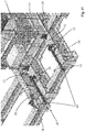
- the transfer means 49 (arranged for moving the corresponding movable tower 2 along the corresponding longitudinal track 48) advantageously comprise one or more displacement actuators 50, preferably of linear type, obtained in particular by means of third hydraulic cylinders.
- each displacement actuator 50 is provided with two elongated components 51, 52 movable in mutual extension and retraction.
- Such elongated components 51, 52 comprise a reaction component 51 constrained to the corresponding longitudinal track 48 and an action component 52 constrained to the movable tower 2, and in particular to the base 37 of the movable tower 2 itself.
- reaction component 51 can be constrained to the movable tower 2 and the action component 52 can be constrained to the corresponding longitudinal track 48.
- the reaction component 51 comprises a hollow jacket and the action component 52 comprises a piston inserted in the aforesaid hollow jacket.
- the reaction component 51 is removably constrained to the longitudinal track 48 by means of a coupling mechanism 53, which is fixed to the aforesaid reaction component 51 and is removably engaged with the corresponding longitudinal track 48, e.g. by means of pins constrainable to corresponding seats made in the longitudinal track 48 itself.
- the displacement actuator 50 In operation, in order to move each movable tower 2 along the corresponding longitudinal track 48, the displacement actuator 50 is driven to operate according to the following operating steps, assuming that such displacement actuator 50 operates in traction on the movable tower 2 and starting from a configuration in which the displacement actuator 50 is retracted and the coupling mechanism 53 is constrained to the longitudinal track 48:
- the apparatus 1 comprises only one station at which the transverse track 20 and the moving means 23 are arranged and in which the reel 4 is intended to be arranged, without arranging other stations with further reels.
- One object of the present invention is also constituted by a method for operating an apparatus 1 for unwinding cables on seabeds of the above-described type.
- the present method provides for a step for setting control means of the apparatus 1, in which an operator, in particular by means of the control panel of the electronic control unit, sets the operating parameters necessary for the operation of the apparatus 1, such as the diameter and the length of the drum 5 of the reel 4, the diameter of the cable 6, the number of rows 9 of coils 10 of the reel 4, the number of coils 10 of each row 9, the initial position of the terminal coil 10' of the reel 4, the unwinding speed of the cable 6.
- the present method provides for a step of arranging the reel 4 in the first station 45 abutted against the first abutment seat 46.
- the step of arranging the reel 4 is obtained by means of a crane driven to bring the reel 4 from a dock or from a transport ship to the first abutment seat 46 of the first station 45 of the apparatus 1.
- the aforesaid arranging step provides for arranging the further reel 4' in the second station 47.
- the two movable towers 2 are moved away from each other in particular by means of driving the connection actuators 39, in a manner so as to arrange the two movable towers 2 at a distance from each other sufficient for allowing the interposition of the reel 4 between the two movable towers 2 themselves.
- the present method preferably provides for a step of aligning the hubs 3 with the reel 4, in which advantageously the hub-holder groups 12 are driven to slide along the guide seat 36 of the corresponding movable tower 2, in particular by means of the actuation of the aforesaid movement system 33, in order to arrange the hubs 3 with the first rotation axis W1 aligned with the longitudinal axis L of the drum 5 of the reel 4.
- the present method provides for a step of engaging the hubs 3 with the reel 4, and in such engaging step the hubs 3 are connected to the corresponding ends 7, 8 of the drum 5 of the reel 4 in order to rotatably support the reel 4 itself.
- the movable towers 2 are driven to be moved close to each other, preferably by means of driving the connection actuators 39, until each hub 3 is brought to be engaged with the corresponding end 7, 8 of the drum 5 of the reel 4.
- a step is provided for lifting the reel 4 from the first abutment seat 46 of the first station 45. More in detail, in such lifting step, the hub-holder groups 12 are driven (in particular by means of the movement system 33) to be moved upward along the guide seats 36 of the corresponding movable towers 2 in order to separate the reel 4 from the first abutment seat 46, so as to allow the rotation of the reel 4 itself.
- the present method comprises a step of unwinding the cable 6 from the drum 5 of the reel 4, in which the reel 4 is driven by the hubs 3 to rotate around the first rotation axis W1 in order to unwind the coils 10 of the cable 6 in succession from the drum 5.
- control means command the movement means 11, and in particular the motors 14 of the hub-holder groups 12, to rotate the hubs 3 so as to rotate the reel 4 in a rotation direction such to unwind the cable 6 from the drum 5 of the reel 4 itself.
- the cable 6 is unwound from the drum 5 at the terminal coil 10' of the reel 4 and is engaged to the transmission means 16 (and in particular to the transmission pulley 17) in order to be transmitted downward so as to enter into the space 101 of the support platform 100 and then descend towards the seabeds.
- the coils 10 of the outermost row 9" are unwound one after the other starting from the terminal coil 10'.
- the next coil 10 (of the row 9") is unwound, which therefore becomes the new terminal coil 10'.
- the cable 6 being unwound is moved along the first rotation axis W1 from one of the ends 7, 8 of the drum 5 of the reel 4 to the other, being brought to the current terminal coil 10' which is unwound from the drum 5 itself.
- the present method comprises a step of determining the position of the current terminal coil 10' along the first rotation axis W1.
- such position is calculated by the electronic module of the identification means of the apparatus 1 on the basis of the operating parameters set in the aforesaid setting step and also preferably based on the measurement of rotation speed of the reel 4 measured by the detection means of the apparatus 1.
- the position of the current terminal coil 10' of the reel 4 is measured by the aforesaid positioning sensor which sends a corresponding measurement signal to the electronic control unit of the control means, which commands the movement of the movable towers 2 along the transverse track 20 according to a feedback control system.
- the method comprises a step of moving the movable towers 2 in a same direction along the moving direction T as a function of the position of the current terminal coil 10' identified in the aforesaid determining step.
- the movable towers 2 are driven to be moved in a manner such to arrange the current terminal coil 10' of the reel 4 substantially aligned with the unwinding direction Z orthogonal to the first rotation axis W1 of the hubs 3, passing between the movable towers 2 and intercepted by the transmission means 16.
- the movable towers 2 are driven to slide together in the first direction V 1 of the moving direction T of the transverse track 20 directed towards the first end side 21 of the transverse track 20 itself, or in the second direction V2 of the moving direction T directed towards the second end side 22 of the transverse track 20.
- the movable towers 2 when the movable towers 2 are moved in the aforesaid first direction V1, the movable towers 2 approach the first end side 21 of the transverse track 20, and when the movable towers 2 are moved in the aforesaid second direction V2, the movable towers 2 approach the second end side 22 of the transverse track 20.
- the moving means 23 carry the two movable towers 2 (and hence the reel 4) into a position substantially equidistant from the two end sides 21, 22 of the transverse track 20.
- the moving means 23 carry the two movable towers 2 and the reel 4 towards the end side 22, 21 of the transverse track 20 opposite the aforesaid end 7, 8 of the drum 5.
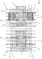
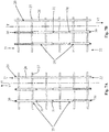
- the movable towers 2 are driven to be moved in the first direction V 1 of the moving direction T, moving close to the first end side 21 of the transverse track 20 (as illustrated in the embodiment of figure 2 ). If the coils 10 of the cable 6 of the reel 4 are unwound from the second end 8 to the first end 7 of the drum 5, the movable towers 2 are driven to be moved in the second direction V2 of the moving direction T, moving close to the second end side 22 of the transverse track 20.
- the actuator devices 25 of the moving means 23 are movable between two end stop positions, illustrated in the embodiments of figures 7A and 7B , including a first end stop position towards the first end side 21 of the transverse track 20 (as illustrated in the embodiment of figure 7A ) and a second end stop position towards the second end side 22 of the transverse track 20 (as illustrated in the embodiment of figure 7B ).
- the movable towers 2 are moved along the moving direction T by a movement section of length substantially equal to the diameter of the cable 6, in a manner so as to compensate for the movement of the cable 6 from the current terminal coil 10' (just unwound) to the following terminal coil 10' which corresponds to the coil 10 of the row 9 following the aforesaid current terminal coil 10' (just unwound).
- the movable towers 2 are driven to be moved along the moving direction T with overall linear speed proportional to the rotation speed of the reel 4 around the first rotation axis W1.
- the rotation speed of the reel 4 is obtained by means of the aforesaid detection means (preferably comprising one or more aforesaid angular position transducers), which send to the electronic control unit of the apparatus 1 signals relative to the detected rotation speed of the reel 4 itself.
- the electronic control unit following the reception of the aforesaid measurement signals by the detection means, commands the movement of the movable towers 2 along the transverse track 20 with overall linear speed proportional to the rotation speed of the reel 4, with a proportionality factor determined as a function, in particular, of the size of the reel 4 and of the cable 6.
- the movable towers 2 are driven to be moved along the moving direction T with an intermittent movement comprising first time intervals, in which the movable towers 2 are moved a specific travel section, and second time intervals alternated with the first intervals; in such second intervals, the movable towers 2 are stopped with respect to the moving direction T.
- intermittent movement advantageously allows controlling, in a more reliable manner, the extension and retraction movement of the actuator devices 25 which, having large size (e.g. half-meter diameter and weight of about a dozen tons), are subjected to high resistance due to the dynamic friction, making a precise continuous movement thereof difficult.
- the overall linear speed of the latter is considered equal to the average speed of the movable towers 2 calculated with respect to each aforesaid first interval (in which the movable towers 2 is moved) and the subsequent second interval (in which the movable towers 2 are stopped).
- the movable towers 2 are driven to be moved along the transverse track 20 with a continuous movement.
- the rotation of the reel 4 is stopped by means of in particular stopping the motors 14 of the movement means 11 commanded by the control means of the apparatus 1.
- the present method preferably comprises a step of lowering the reel 4 onto the first abutment seat 46 of the first station 45.
- the hub-holder groups 12 are driven to be moved (in particular by means of the movement system 33) downward along the guide seats 36 of the corresponding movable towers 2, until the reel 4 is abutted against the first abutment seat 46.
- a step is also provided for disengaging the hubs 3 from the reel 4, and in such disengaging step the hubs 3 are separated from the drum 5 of the reel 4 itself.
- the movable towers 2 are driven to be moved away from each other, preferably by means of driving the connection actuators 39, until each hub 3 is separated from the corresponding end 7, 8 of the drum 5 of the reel 4.
- the present method then provides for a step of translating the movable towers 2 from the first station 45 to the second station 47 in which the further reel 4' to employed is arranged.
- the moving means 23 are driven for moving the movable platform 24 until the first sections 48' of the longitudinal tracks 48 (made on the movable platform 24 itself) are arranged aligned with the corresponding second sections 48" of the longitudinal tracks 48 (made on the further movable platform 24' of the second station 47).
- the two movable towers 2 are driven to be moved on the corresponding longitudinal tracks 48 from the first station 45 to the second station 47, in particular by means of driving the transfer means 49.
- the apparatus 1 is driven for unwinding the cable of the further reel 4' in a manner entirely analogous to that provided by the above-described operating steps.
Abstract
Description
- The present invention regards an apparatus for unwinding cables on seabeds and a method of operation of an apparatus for unwinding cables on seabeds.
- The present apparatus and the method fall within the industrial field of the production of offshore equipment and are intended to be used in the field of laying cables on beds of seas, lakes, basins, etc. More in detail, the apparatus that is the object of the present invention is intended to be mounted on ships in order to unwind reels of cables on a seabed, such as in particular flexible cables (for example an energy transmission cable, a data transmission signal cable, etc.) or cables made of yielded steel employed for example for injecting compressed air or water in an oil well.
- In particular, the reels of cables intended to be unwound by means of the present apparatus and method have diameter of about 6 to 24 meters and weight of about 200 to 2500 tons.
- As is known, the apparatuses for unwinding cables on seabeds, such as the apparatuses of known type described in the
patents EP 2743560 andGB 2046207 - More in detail, each tower is preferably obtained by means of two columns that are parallel to and counter-facing each other, between which a hub-holder group that rotatably supports the reel is slidably engaged in opposite guides. The reel is usually constituted by a drum around which the cable is wound, which is rotated by means of the actuation of motor means directly mounted on the hub-holder group of the apparatus.
- The apparatus also comprises at least two vertical hydraulic pistons, each of which mounted between the two columns of each tower for the lifting and lowering of the reel between a lowered loading position and a raised work position.
- Two horizontal hydraulic pistons are also provided for, mounted on the base in order to move the two towers towards or away from each other along rails, in order to allow the hub-holder group respectively to be engaged with the drum of the reel or be detached from the drum itself.
- The apparatuses of known type for unwinding cables on seabeds also comprise a further laying tower, which is laid on the deck of a ship in front of the reel supported by the two aforesaid towers at several meters distance from the reel itself. At the top of the laying tower, a transmission pulley is rotatably mounted which abuttingly receives the cable that comes from the reel, in a manner such that the cable bends around the transmission pulley and vertically descends in order to enter into a space made on the deck of the ship at the feet of the laying tower, so as to bring the cable itself onto the seabed.
- In particular, the transmission pulley is perimetrically provided with an annular seat (delimited between two projecting side walls), within which the cable section is inserted that lies on the transmission pulley itself, in a manner so as to guide the movement of the cable around the axis of the transmission pulley.
- The apparatus also comprises tensioning means, mounted on the laying tower and acting on the cable in order to keep it constantly under tension during the unwinding of the cable itself.
- As is known, cable reels have very high weight, typically many hundreds of tons, and can have very large size, for example with a radius between about 6 and 11 meters (and even up to 24 meters) and an axial length of about 5-6 meters.
- The drum of the reel (for example made of steel) has cylindrical form and is horizontally extended between two ends thereof, carrying the cable to be laid externally mounted thereon.
- The cable is wound around the drum of the reel, forming multiple rows of coils arranged on top of each other. More in detail, each row of coils is composed of multiple coils wound around the axis of the drum and arranged next to each other from one end of the drum itself to the other. In addition, the rows of coils are arranged wound around each other, starting from an internal coil, wound around the surface of the drum of the reel, to an external row from which the cable exits from the reel in order to be brought towards the transmission pulley mounted on the laying tower.
- In operation, the reel is driven by the motor means to rotate, in order to unwind the cable that consequently slides towards the transmission pulley according to a laying direction orthogonal to the hub rotation axis. The cable, then, descends vertically downward from the transmission pulley in order to enter within the space of the ship deck.
- More in detail, following the rotation of the reel, the coils of the cable are unwound from each row, one after the other starting from the coil arranged at one of the ends of the drum of the reel up to the other end of the drum itself.
- Since, as stated, the drum of the reel has several meters length (e.g. 5-6 meters), while the coils placed at the ends of the drum are being unwound, the section of cable that is extended from the reel to the transmission pulley forms a relatively high angle with respect to the aforesaid laying direction (orthogonal to the hub rotation axis).
- This causes the coil being unwound to overlap on the subsequent coil, in particular being inserted between the latter coil and the further subsequent coil of the coil row of the reel, generating entanglements that easily cause the jamming of the unwinding movement, variations of the cable tensioning, as well as damage of the cable such as crushing, yielding, variation of the curvature radius angle of the cable, etc.
- In addition, when the cable enters with a high tilt angle (with respect to the laying direction) within the annular seat of the pulley, the cable tends to rub against the perimeter edge of the side walls projecting from the seat itself, causing further risk of damage of the cable itself
- The aforesaid condition with high tilt angle is particular disadvantageous in the laying operations of steel cables, since such steel cables are more easily subjected to being damaged following rubbing and crushing.
- In addition, the verification of the aforesaid jamming and damage conditions requires interrupting the operations of laying and executing repair operations that are particularly long and difficult, since it is necessary to operate on the cable at high heights from the ship deck. More in detail, it is necessary to interrupt the movement of the reel, arrange suitable support frameworks in order to sustain the cable at the damaged parts, cut the cable at such damaged parts and then weld the cable itself, and operation must also occur at over ten meters height from the ship deck. Such operations require interrupting the operations of laying the cable, even for a week, with consequent delays in the completion of the work and considerable additional expenses (even hundreds of thousands of dollars) to be sustained, for example for the maintenance of the ship on which the apparatus is mounted.
- The international patent
WO 2009/077711 describes an apparatus for unwinding cables on seabeds, which comprises a straightener group intended to receive the cable unwound from the reel, which is movable to slide parallel to its rotation axis in order to align the unwound cable with the aforesaid straightener group. The apparatus described inWO 2009/077711 does not allow ensuring optimal reliability conditions during the unwinding of the cable on the seabed. - The problem underlying the present invention is therefore that of overcoming the drawbacks of the abovementioned prior art, by providing an apparatus for unwinding cables on seabeds and a method for operating said apparatus, which are entirely reliable in operation and, in particular, which allow unwinding the cables without the risk of damaging the latter.
- A further object of the present invention is to provide an apparatus for unwinding cables on seabeds and a method for operating said apparatus, which allow executing the laying operations in relatively quick times and with relatively limited costs.
- A further object of the present invention is to provide an apparatus for unwinding cables on seabeds, which occupies relatively limited spaces.
- A further object of the present invention is to provide an apparatus for unwinding cables on seabeds, which is structurally simple and inexpensive to make.
- The technical characteristics of the invention, according to the aforesaid objects, can be clearly seen in the contents of the below-reported claims, and the advantages thereof will be clearer in the following detailed description, made with reference to the enclosed drawings, which represent a merely exemplifying and non-limiting embodiment of the invention, in which:
-
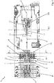
figure 1 shows a top plan view of the apparatus, object of the present invention; -
figure 2 shows a top plan view of the apparatus illustrated infigure 1 , in which the movable towers of the apparatus are arranged in a different operating position; -
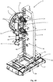
figure 3 shows a perspective view of a detail of the present apparatus, relative to the movable towers and to moving means for such movable towers; -
figure 4 shows a plan view of the apparatus illustrated infigure 3 ; -
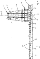
figure 5 shows a side view of the apparatus illustrated infigure 3 ; -
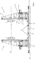
figure 6 shows a front view of the apparatus illustrated infigure 3 ; -
figures 7A and 7B illustrated two plan views of the moving means of the present apparatus arranged in two corresponding operating positions; -
figure 8 shows a front view of a detail of the apparatus relative to the two movable towers with a reel of the cable to be unwound arranged between the movable towers themselves; -
figure 9 shows a sectional view of the reel illustrated infigure 8 ; -
figure 10 shows a perspective view of one of the movable towers of the apparatus with some parts removed in order to better illustrated other parts; -
figure 11 shows a detail of the present apparatus relative to transfer means adapted to move the movable towers along longitudinal tracks of the apparatus itself. - With reference to the set of drawings,
reference number 1 overall indicates the apparatus for unwinding cables on seabeds, object of the present invention. - The
present apparatus 1 is intended to be advantageously employed in offshore work sites for laying cables on the seabed, e.g. of seas, lakes, water basins. - In particular, the
present apparatus 1 is employable for laying cables made of yielded steel, intended to be used for example for injecting compressed air or water into an oil well, or also for laying flexible cables intended for various applications, such as energy transmission cables, data transmission signal cables (e.g. made of optical fiber), flexible tubes and more generally flexible umbilical cords. - The
present apparatus 1 is intended to be arranged on asupport platform 100 such as a deck of a ship or of a lighter or of a pontoon equipped for operating in an offshore work site.Such support platform 100 is provided with aspace 101 vertically extended in a through manner through the support platform itself and through which the cable to be unwound is made to descend into the sea towards the seabeds, as described in detail hereinbelow. - With reference to the enclosed figures, the
apparatus 1 comprises twomovable towers 2 arranged parallel to and spaced from each other and intended to be arranged on thesupport platform 100. The twomovable towers 2 are advantageously extended according to corresponding vertical extension directions X. - In addition, the
apparatus 1 comprises twohubs 3 which are arranged facing each other, are rotatably constrained to the correspondingmovable towers 2 and are susceptible of being mechanically engaged with areel 4 of the cable to be unwound. - In particular, each
hub 3 is rotatable around a first rotation axis W1, preferably horizontal and orthogonal to the first extension directions X of the twomovable towers 2. - Advantageously, with reference to the embodiment reported in
figures 8 and9 , thereel 4 is provided with adrum 5 intended to be arranged coaxially with respect to the first rotation axis W1 and with acable 6 wound around thedrum 5 itself. - Preferably, the
drum 5 of the reel 4 (made for example of steel) has substantially cylindrical form and is extended according to a (preferably horizontal) longitudinal axis L thereof between afirst end 7 and asecond end 8, which are intended to be engaged with thecorresponding hubs 3 of theapparatus 1. In particular, thecable 6 is constituted by an elongated element intended to be laid offshore and having a diameter (or more generally a width) comprised for example between 8 and 25 cm and a weight comprised for example between 20 and 50 kg per linear meter. - Still with reference to the embodiments illustrated in
figures 8 and9 , thecable 6 of thereel 4 is wound around thedrum 5, forming at least onerow 9 ofcoils 10 arranged side-by-side each other along the first rotation axis W1 and comprising a terminal coil 10' from which thecable 6 is susceptible of being unwound from thedrum 5. - More in detail, the
coils 10 of eachrow 9 are arranged (in succession) between twoend coils 10" preferably arranged in proximity to thecorresponding ends drum 5. - In accordance with the embodiment illustrated in
figures 8 and 9 , thecable 6 is wound around thedrum 5 of thereel 4, forming multipleaforesaid rows 9 ofcoils 10 arranged on top of each other. More in detail, therows 9 ofcoils 10 are arranged wound on each other, starting from an innermost row 9', wound around the external surface of thedrum 5, to anoutermost row 9" from which thecable 6 is susceptible of being unwound at the aforesaid terminal coil 10'. - The
apparatus 1 according to the invention comprises movement means 11 mechanically connected to thehubs 3 and adapted to rotate the latter around the first rotation axis W1 in order to drive thereel 4 to rotate around the first rotation axis W1 itself, so as to at least unwind thecable 6 from thedrum 5 at the terminal coil 10'. - In particular, following the aforesaid rotation movement, the
coils 10 of theoutermost row 9" are unwound one after the other starting from the terminal coil 10'. When the terminal coil 10' has been completely unwound from thedrum 5, thenext coil 10 of theoutermost row 9" is unwound, which therefore becomes the new terminal coil 10'. In this manner, thecable 6 being unwound is moved along the first rotation axis W from one end of theends drum 5 of thereel 4 to the other, being brought to the terminal coil 10' which is unwound from thedrum 5 itself. - When all the
coils 10 of theoutermost row 9" have been unwound, theunderlying row 9 is unwound (starting from one of the coils ofend 10" up to the other coil ofend 10"), until the innermost row 9' ofcoils 10 of thereel 4 has been unwound. - Advantageously, with reference to
figure 10 , the movement means 11 of theapparatus 1 comprise two hub-holder groups 12, each of which mounted on the correspondingmovable tower 2 and in turn carrying thecorresponding hub 3 rotatably mounted thereon. - Advantageously, each hub-
holder group 12 comprises asupport body 13, preferably metallic with box-like form, for example with parallelepiped form, which rotatably carries, mounted thereon, the correspondinghub 3 in particular having the shape of a cylindrical body peripherally provided with notches adapted to be engaged in corresponding teeth made on the internal profile of a connection flange (of type per se known to the man skilled in the art) fixed to thecorresponding end drum 5 of thereel 4, in order to transmit thereto the rotation motion for unwinding thecable 6. On thesupport body 13 of each hub-holder group 12, at least one motor 14 (and preferably two motors 14) is respectively mounted, for example of electric or oil-hydraulic type, andsuch motor 14 is mechanically connected to thehub 3 in order to rotate the latter together with thereel 4. According to the invention, with reference to the embodiments offigures 1 and2 , theapparatus 1 comprises a layingtower 15 intended to be fixed on thesupport platform 100 and transmission means 16, which are mounted on the layingtower 15 and are arranged in particular in front of twomovable towers 2. - More in detail, the transmission means 16 are arranged to intercept an unwinding direction Z orthogonal to the first rotation axis W1 of the
hubs 3 and passing between themovable towers 2. - The transmission means 16 are susceptible of receiving, in engagement, a section of the
cable 6 unwound from thedrum 5 of thereel 4 and for transmitting such section of thecable 6 downward in order to make the latter enter into thespace 101 of thesupport platform 100, so as to make thecable 6 itself descend into the sea towards the seabeds. - Advantageously, the laying
tower 15, in particular obtained by means of metallic structures, is vertically extended between a base thereof, intended to be fixed on thesupport platform 100 at thespace 101, and a top thereof at which the transmission means 16 are mounted. - With reference to the embodiment illustrated in
figures 1 and2 , the transmission means 16 comprise atransmission pulley 17 mounted at the top of the layingtower 15, arranged aligned with the unwinding direction Z and rotatably around a second rotation axis W2 parallel to the first rotation axis W1 of thehubs 3 and preferably horizontal. - In operation, the
transmission pulley 17 is adapted to receive, abuttingly on the upper part, the unwoundcable 6 coming from thereel 4 and is drivable to rotate around the second rotation axis W2 thereof in order to guide thecable 6 towards thespace 101 of thesupport platform 100. More in detail, thecable 6 at thetransmission pulley 17 bends downward, following the curvature of thetransmission pulley 17 itself so as to descend towards thespace 101. - In particular, the
transmission pulley 17 is perimetrically provided with an annular seat 18 (delimited between two projecting side walls 19) within which the section ofcable 6 is susceptible of being inserted, such section lying on thetransmission pulley 17 itself, in a manner so as to guide the movement of thecable 6 around the second rotation axis W2 of thetransmission pulley 17. - The
apparatus 1 also comprises tensioning means, mounted on the layingtower 15, operating on thecable 6 in order to keep it constantly taut during the unwinding of thecable 6 itself. Such tensioning means are of type per se known to the man skilled in the art and therefore will not be described in detail hereinbelow. - In accordance with the idea underlying the present invention, the
apparatus 1 comprises atransverse track 20, which is intended to be arranged on thesupport platform 100 and carries, slidably constrained thereto, themovable towers 2. - More in detail, the
transverse track 20 is extended, between a first side thereof ofend 21 and a second side thereof ofend 22, according to a moving direction T parallel to the first rotation axis W1 of thehubs 3 and preferably rectilinear and horizontal. - Advantageously, the
reel 4 is intended to be engaged between the twomovable towers 2 arranged with the first and thesecond end drum 5 respectively directed towards the first and thesecond end side transverse track 20. - The
apparatus 1 also comprises moving means 23 mechanically connected to themovable towers 2 and adapted to move the latter along thetransverse track 20 according to the moving direction T. - In particular, the moving means 23 are arranged for simultaneously moving the two
movable towers 2 in a same direction as the aforesaid moving direction T in order to maintain the terminal coil 10' of thereel 4 aligned with the transmission means 16 (according to the unwinding direction Z) during the unwinding of thecable 6 from thereel 4 itself - More in detail, the moving means 23 are arranged for moving the two movable towers to selectively slide together in a first direction V1 of the moving direction T (in order to move the
movable towers 2 towards thefirst end side 21 of the transverse track 20) or in a second direction V2 of the moving direction T (in order to move themovable towers 2 towards thesecond end side 22 of the transverse track 20). - According to the invention, the
apparatus 1 comprises position identification means (not illustrated in the enclosed figures) arranged for determining a position parameter indicative of the position, along the first rotation axis W1, of the terminal coil 10' of thecable 6 of thereel 4, and control means (also not illustrated in the enclosed figures) operatively connected to the position identification means and to the moving means 23 and arranged for commanding, as a function of the aforesaid position parameter, the moving means 23 to move themovable towers 2 along the moving direction T in order to maintain the terminal coil 10' of thereel 4 substantially aligned with the aforesaid unwinding direction Z. In particular, by "substantially aligned" it is intended that thecable 6, at the terminal coil 10', is arranged within a deviation interval (parallel to the first rotation axis W1) centered on the unwinding direction Z and extended from both sides of the unwinding direction Z itself for a length equal to about three times the diameter of thecable 6 or, preferably, about equal to the diameter of thecable 6 itself. The aforesaid characteristics of the present invention allow, during the operation of theapparatus 1, maintaining the section ofcable 6, which is unwound from thereel 4 and which is extended between thereel 4 itself and the transmission means 16, substantially aligned with the unwinding direction Z. This advantageously allows maintaining the terminal coil 10' of thereel 4 parallel to theother coils 10, preventing the terminal coil 10' from overlapping on theadjacent coils 10 and hence avoiding entanglements of thecable 6 that could cause jamming and damage of thecable 6 itself, described above in the discussion of apparatuses of known type. - In addition, by maintaining the section of
cable 6 between thereel 4 and the transmission means 16 substantially aligned with the unwinding direction Z, thecable 6 is substantially parallel to theannular seat 18 of thetransmission pulley 17, preventing thecable 6 itself from being damaged by rubbing against the edges of the projectingside walls 19 of thetransmission pulley 17. - Advantageously, in accordance with the embodiment illustrated in
figures 3-6 , the moving means 23 (adapted to move themovable towers 2 along the transverse track 20) comprise amovable platform 24 which is slidably mounted on thetransverse track 20 and carries themovable towers 2 mounted in abutment thereon, and at least oneactuator device 25 mechanically connected to themovable platform 24 and arranged for moving the latter to slide along thetransverse track 20. - Advantageously, the
transverse track 20 comprises a first metallic framework, which is in particular provided with multiple firstlongitudinal bars 26 parallel to the moving direction T of thetransverse track 20 itself and preferably connected together by one or more first transverse bars 27. Advantageously, themovable platform 24 comprises a second metallic framework in particular provided with secondlongitudinal bars 28 parallel to the moving direction T of thetransverse track 20 and preferably connected together by second transverse bars 29. - Preferably, in accordance with the embodiment illustrated in the enclosed figures, the moving means 23 comprise multiple aforesaid actuator devices 25 (e.g. four), of which in particular at least one of such actuator devices 25 (e.g. two) is placed at the
first end side 21 of thetransverse track 20, and at least another of such actuator devices 25 (e.g. two) is placed at thesecond end side 22 of thetransverse track 20 itself (in accordance with the embodiments illustrated in particular infigures 7A and 7B ). - Advantageously, each
actuator device 25 of the movingmeans 23 is of linear type and is drivable to be moved in extension and retraction according to a direction parallel to the moving direction T of thetransverse track 20. - In particular, each
actuator device 25 comprises a first hydraulic cylinder. The control means of theapparatus 1 comprise an oil-hydraulic control unit operatively connected to each hydraulic cylinder in order to control the operation thereof. - Preferably, each
actuator device 25 comprises afirst end 30 constrained to thetransverse track 20 preferably at thecorresponding end side second end 31 constrained to themovable platform 24. - In particular, each
actuator device 25 has an operating travel of at least one meter (e.g. of about three meters) so to be able to move themovable towers 2 fromend side transverse track 20 to the other. - Advantageously, each
actuator device 25 is at least partially inserted in at least one correspondingpassage 32 made in the thickness of themovable platform 24. In particular, eachactuator device 25 is inserted in thecorresponding passage 32 obtained by means of a through hole made in the corresponding secondtransverse bar 29 of themovable platform 24. - Advantageously, the control means of the
apparatus 1 comprise at least one electronic control unit, which in particular is provided with a PLC and is preferably connected to the aforesaid oil-hydraulic control unit in order to control the operation of the first hydraulic cylinders of theactuator devices 25. Advantageously, the electronic control unit is provided with a control panel by means of which an operator can set operating parameters necessary for the operation of theapparatus 1, such as the diameter and the length of thedrum 5 of thereel 4, the diameter of thecable 6, the number ofrows 9 ofcoils 10 of thereel 4, the initial position of the terminal coil 10' of thereel 4, the unwinding speed of thecable 6. - The aforesaid operating parameters allow the position identification means to determine, instant by instant during the rotation of the
reel 4, the position of the current terminal coil 10' along the first rotation axis W1 of thehubs 3. - In accordance with a different embodiment, the identification means comprise at least one positioning sensor arranged for measuring instant by instant the position (along the first rotation axis W1) of the
cable 6 at the current terminal coil 10'. - In particular, such positioning sensor for example comprises a magnetostrictive sensor, or an illumination sensor or a resistive sensor.
- Advantageously, the aforesaid position identification means comprise an electronic module, for example integrated with the electronic control unit of the control means of the
apparatus 1. - Advantageously, the
apparatus 1 comprises detection means (not illustrated in the enclosed figures) arranged for measuring the rotation speed of thereel 4 around the first rotation axis W1 and operatively connected to the control means in order to send to the latter measurements of such rotation speed. - The control means are arranged for moving the
movable towers 2 along thetransverse track 20 with overall linear movement speed proportional to the rotation speed of thereel 4, as a function of the aforesaid measurements received from the detection means. - In particular, the movement means are arranged for commanding the
hubs 3 to rotate in a manner such that the linear unwinding speed of the cable 6 (corresponding in substance with the speed with which thecable 6 is lowered towards the seabeds) is substantially constant, e.g. with value between 2 and 10 centimeters per minute. - Since the more
external rows 9 ofcoils 10 of thereel 4 have diameter greater than the moreinternal rows 9, in order to maintain constant the unwinding speed of thecable 6, the movement means 11 are commanded by the control means in order to rotate the hubs 3 (and hence the reel 4) with angular speed that increases when passing from the unwinding of a moreexternal row 9 ofcoils 10 to the subsequent moreinternal row 9 ofcoils 10. Therefore, the moreinternal rows 9 ofcoils 10 are unwound with greater angular speed than the moreexternal rows 9 and, hence, when the moreinternal rows 9 are unwound, thecable 6 is moved from one of theends drum 5 of thereel 4 to the other (along the first rotation axis W1) with greater speed than when the moreexternal rows 9 are unwound. - The detection means measure the rotation speed of the
reel 4 by sending corresponding measurement parameters to the control means, which, following variations of the angular speed of thereel 4, command corresponding variations of the movement of themovable towers 2 along thetransverse track 20. - In substance, when the more
internal rows 9 ofcoils 10 are unwound, themovable towers 2 are commanded to be moved on thetransverse track 20 with overall linear speed that is greater than when moreexternal rows 9 ofcoils 10 are unwound. - Advantageously, the detection means comprise at least one angular position transducer operatively associated with at least one of the
hubs 3 of theapparatus 1. - Preferably, the angular position transducer is operatively connected to at least one of the
motors 14 of at least one of the hub-holder groups 12, in order to measure the angular speed of the output shaft of themotor 14; from such angular speed, the rotation speed of thecorresponding hub 3 is obtained along with the rotation speed of thereel 4. - In particular, the detection means comprise multiple aforesaid angular position transducers, each of which applied to the
corresponding motor 14 of the hub-holder groups 12. - Advantageously, each angular position transducer comprises an encoder, preferably of absolute type, connected to the
corresponding motor 14. - In accordance with the embodiment illustrated in the enclosed
figures 6 ,8 ,10 and11 , eachmovable tower 2 comprises a base 34 advantageously abutted against themovable platform 24 and twocolumns 35, which are arranged in abutment againstsuch base 34, are positioned parallel to and spaced from each other and together define aguide seat 36 in which the corresponding hub-holder group 12 is inserted. - Preferably, the
base 34 of eachmovable tower 2 comprises a base 37 arranged in abutment against themovable platform 24, and abase block 38 slidably abutted above thebase 37 and carrying the two correspondingcolumns 35 fixed thereto. - Advantageously, the
apparatus 1 comprisesconnection actuators 39 mechanically connected to the correspondingmovable towers 2 and arranged for moving the latter mutually close or away (according to a direction parallel to the firstrotation axis W 1 of the hubs 3), respectively in order to bring thehubs 3 to engage or disengage the corresponding ends 7, 8 of thedrum 5 of thereel 4. - Preferably, the
aforesaid connection actuators 39, in particular obtained with second hydraulic cylinders, are advantageously arranged parallel to the first rotation axis W of thehubs 3 and operate on thebase block 38 of the base 34 in order to integrally move thecolumns 35 and the hub-holder group 12, so as to move thecorresponding hub 3 to engage or disengage thedrum 5 of thereel 4. - In particular, each
connection actuator 39 comprises a reaction end 39' engaged with thebase 37 and anaction end 39" engaged with thebase block 38, and it is drivable in extension and retraction for moving thebase block 38 itself. - Advantageously, the
apparatus 1 comprises amovement system 33 arranged for vertically moving eachhub 3 along the correspondingmovable tower 2, in particular in order to align thehub 3 with thedrum 5 of thereel 4 so as to engage thehub 3 with thereel 4 itself and for lifting and lowering the latter. - In particular, with reference to the embodiment illustrated in
figure 10 , themovement system 33 comprises, for each hub-holder group 3:multiple anchorage elements 40 made on thecolumns 35 of the correspondingmovable tower 2, areaction bar 41 arranged in theguide seat 36 of the correspondingmovable tower 2,first locking devices 42 mounted on the hub-holder group 12,second locking devices 43 mounted on thereaction bar 41, and at least onemovement actuator 44 placed to connect between the hub-holder group 12 and thereaction bar 41, as described in detail in the Italian patent application No.PD2012A000374 page 10line 1 topage 16line 20, to be considered enclosed for reference purposes with the present patent. - Advantageously, the
apparatus 1 comprises afirst station 45 provided with afirst abutment seat 46 in which thereel 4 is intended to be arranged. Preferably, thefirst abutment seat 46 comprises a first metal work support saddle against which thereel 4 is intended to be abutted. - At such
first station 45, thetransverse track 20 and the moving means 23 of theapparatus 1 are arranged. - Advantageously, in accordance with the particular embodiment illustrated in
figures 1-5 , theapparatus 1 comprises asecond station 47 provided with a further abutment seat (not illustrated in the enclosed figures) in which a further reel 4' is intended to be arranged. - In particular, the
apparatus 1 comprises, at suchsecond station 47, a further transverse track 20' and further moving means 23' preferably having the same above-described characteristics relative to thetransverse track 20 and to the moving means 23 arranged at thefirst station 45. - In particular, the further moving means 23' comprise a further
movable platform 24' slidably mounted on the aforesaid further transverse track 20' and at least one further actuator device 25' mechanically connected to the furthermovable platform 24' and arranged for moving such furthermovable platform 24' along the further transverse track 20'. - Advantageously, the
present apparatus 1 comprises twolongitudinal tracks 48, which are arranged parallel to each other and are extended between thefirst station 45 and thesecond station 47. The correspondingmovable tower 2 is slidably arranged on each of suchlongitudinal tracks 48 in order to allow the movement thereof between thefirst station 45 and thesecond station 47. - For such purpose, the
apparatus 1 comprises transfer means 49 (described in detail hereinbelow), which are mechanically connected to themovable towers 2 and are arranged for moving the latter along the correspondinglongitudinal tracks 48 between the twostations - Advantageously, the
longitudinal tracks 48 are extended parallel to each other according to corresponding longitudinal directions S, preferably rectilinear. - In particular, each
longitudinal track 48 comprises at least two corresponding longitudinal members connected together by multiple corresponding reinforcement crosspieces. - Advantageously, the two longitudinal tracks are made on the
movable platforms - Preferably, each
longitudinal track 48 comprises a first section 48' made on themovable platform 24 arranged in thefirst station 45 and asecond section 48" made on the furthermovable platform 24' arranged in thesecond station 47. - During the movement of the
movable towers 2 between thefirst station 45 and thesecond station 47, the movingmeans 23, 23' arrange the correspondingmovable platforms longitudinal track 48 aligned with the correspondingsecond section 48". - Advantageously, with reference to the embodiment of
figure 10 , the transfer means 49 (arranged for moving the correspondingmovable tower 2 along the corresponding longitudinal track 48) advantageously comprise one ormore displacement actuators 50, preferably of linear type, obtained in particular by means of third hydraulic cylinders. - In particular, each
displacement actuator 50 is provided with twoelongated components - Such
elongated components reaction component 51 constrained to the correspondinglongitudinal track 48 and anaction component 52 constrained to themovable tower 2, and in particular to thebase 37 of themovable tower 2 itself. - Of course, without departing from the protective scope of the present invention and in an entirely equivalent manner, the
reaction component 51 can be constrained to themovable tower 2 and theaction component 52 can be constrained to the correspondinglongitudinal track 48. - Preferably, the
reaction component 51 comprises a hollow jacket and theaction component 52 comprises a piston inserted in the aforesaid hollow jacket. - Preferably, the
reaction component 51 is removably constrained to thelongitudinal track 48 by means of acoupling mechanism 53, which is fixed to theaforesaid reaction component 51 and is removably engaged with the correspondinglongitudinal track 48, e.g. by means of pins constrainable to corresponding seats made in thelongitudinal track 48 itself. - In operation, in order to move each
movable tower 2 along the correspondinglongitudinal track 48, thedisplacement actuator 50 is driven to operate according to the following operating steps, assuming thatsuch displacement actuator 50 operates in traction on themovable tower 2 and starting from a configuration in which thedisplacement actuator 50 is retracted and thecoupling mechanism 53 is constrained to the longitudinal track 48: - releasing the
coupling mechanism 53 fromlongitudinal track 48; - driving the
displacement actuator 50 in extension, in a manner such to move thereaction component 51 along thelongitudinal track 48 away from themovable tower 2; - once again constraining the
coupling mechanism 53 to thelongitudinal track 48; - driving the
displacement actuator 50 in retraction, in a manner such to draw themovable tower 2 close to thereaction component 51 by advancing themovable tower 2 itself along thelongitudinal track 48. - The above-described operating steps are advantageously repeated until the
movable tower 2 is brought into the desired position along the longitudinal track 48 (for example at thefirst station 45 or at thesecond station 47 of the apparatus 1). - In accordance with an embodiment not illustrated in the enclosed figures, the
apparatus 1 comprises only one station at which thetransverse track 20 and the moving means 23 are arranged and in which thereel 4 is intended to be arranged, without arranging other stations with further reels. - One object of the present invention is also constituted by a method for operating an
apparatus 1 for unwinding cables on seabeds of the above-described type. - Hereinbelow, for the same of description simplicity, reference will be made to the same nomenclature introduced up to now, even if it must be intended that the present method can also be obtained with apparatuses not provided with all of the above-described characteristics.
- Advantageously, the present method provides for a step for setting control means of the
apparatus 1, in which an operator, in particular by means of the control panel of the electronic control unit, sets the operating parameters necessary for the operation of theapparatus 1, such as the diameter and the length of thedrum 5 of thereel 4, the diameter of thecable 6, the number ofrows 9 ofcoils 10 of thereel 4, the number ofcoils 10 of eachrow 9, the initial position of the terminal coil 10' of thereel 4, the unwinding speed of thecable 6. - Advantageously, the present method provides for a step of arranging the
reel 4 in thefirst station 45 abutted against thefirst abutment seat 46. - In particular, the step of arranging the
reel 4 is obtained by means of a crane driven to bring thereel 4 from a dock or from a transport ship to thefirst abutment seat 46 of thefirst station 45 of theapparatus 1. - Preferably, in particular if the
apparatus 1 comprisesmultiple stations second station 47. - Advantageously, before the aforesaid arranging step, the two
movable towers 2 are moved away from each other in particular by means of driving theconnection actuators 39, in a manner so as to arrange the twomovable towers 2 at a distance from each other sufficient for allowing the interposition of thereel 4 between the twomovable towers 2 themselves. - The present method preferably provides for a step of aligning the
hubs 3 with thereel 4, in which advantageously the hub-holder groups 12 are driven to slide along theguide seat 36 of the correspondingmovable tower 2, in particular by means of the actuation of theaforesaid movement system 33, in order to arrange thehubs 3 with the first rotation axis W1 aligned with the longitudinal axis L of thedrum 5 of thereel 4. - The present method provides for a step of engaging the
hubs 3 with thereel 4, and in such engaging step thehubs 3 are connected to the corresponding ends 7, 8 of thedrum 5 of thereel 4 in order to rotatably support thereel 4 itself. - In particular, in the engaging step, the
movable towers 2 are driven to be moved close to each other, preferably by means of driving theconnection actuators 39, until eachhub 3 is brought to be engaged with thecorresponding end drum 5 of thereel 4. - Advantageously, a step is provided for lifting the
reel 4 from thefirst abutment seat 46 of thefirst station 45. More in detail, in such lifting step, the hub-holder groups 12 are driven (in particular by means of the movement system 33) to be moved upward along the guide seats 36 of the correspondingmovable towers 2 in order to separate thereel 4 from thefirst abutment seat 46, so as to allow the rotation of thereel 4 itself. - According to the invention, the present method comprises a step of unwinding the
cable 6 from thedrum 5 of thereel 4, in which thereel 4 is driven by thehubs 3 to rotate around the first rotation axis W1 in order to unwind thecoils 10 of thecable 6 in succession from thedrum 5. - In particular, in the aforesaid unwinding step, the control means command the movement means 11, and in particular the
motors 14 of the hub-holder groups 12, to rotate thehubs 3 so as to rotate thereel 4 in a rotation direction such to unwind thecable 6 from thedrum 5 of thereel 4 itself. - In the unwinding step, the
cable 6 is unwound from thedrum 5 at the terminal coil 10' of thereel 4 and is engaged to the transmission means 16 (and in particular to the transmission pulley 17) in order to be transmitted downward so as to enter into thespace 101 of thesupport platform 100 and then descend towards the seabeds. - In particular, following the aforesaid rotation of the
reel 4, thecoils 10 of theoutermost row 9" are unwound one after the other starting from the terminal coil 10'. When the terminal coil 10' has been completely unwound from thedrum 5 of thereel 4, the next coil 10 (of therow 9") is unwound, which therefore becomes the new terminal coil 10'. In this manner, thecable 6 being unwound is moved along the first rotation axis W1 from one of theends drum 5 of thereel 4 to the other, being brought to the current terminal coil 10' which is unwound from thedrum 5 itself. - In particular, following the rotation of the
reel 4, if thecoils 10 of thecable 6 are unwound from thefirst end 7 to thesecond end 8 of thedrum 5, thecable 6, at the terminal coil 10', is moved from thefirst end 7 to thesecond end 8 of thedrum 5. However, if thecoils 10 of thecable 6 are unwound from thesecond end 8 to thefirst end 7 of thedrum 5, thecable 6, at the terminal coil 10', is moved from thesecond end 8 to thefirst end 7 of thedrum 5. - When all the
coils 10 of theoutermost row 9" have been unwound, theunderlying row 9 is unwound (starting from one of the coils ofend 10" up to the other coil ofend 10"), until the innermost row 9' ofcoils 10 of thereel 4 is unwound. - In accordance with the idea underlying the present invention, the present method comprises a step of determining the position of the current terminal coil 10' along the first rotation axis W1.
- Advantageously, such position is calculated by the electronic module of the identification means of the
apparatus 1 on the basis of the operating parameters set in the aforesaid setting step and also preferably based on the measurement of rotation speed of thereel 4 measured by the detection means of theapparatus 1. - Otherwise, the position of the current terminal coil 10' of the
reel 4 is measured by the aforesaid positioning sensor which sends a corresponding measurement signal to the electronic control unit of the control means, which commands the movement of themovable towers 2 along thetransverse track 20 according to a feedback control system. - According to the invention, the method comprises a step of moving the
movable towers 2 in a same direction along the moving direction T as a function of the position of the current terminal coil 10' identified in the aforesaid determining step. - In the moving step, the
movable towers 2 are driven to be moved in a manner such to arrange the current terminal coil 10' of thereel 4 substantially aligned with the unwinding direction Z orthogonal to the first rotation axis W1 of thehubs 3, passing between themovable towers 2 and intercepted by the transmission means 16. - More in detail, in the moving step, the
movable towers 2 are driven to slide together in thefirst direction V 1 of the moving direction T of thetransverse track 20 directed towards thefirst end side 21 of thetransverse track 20 itself, or in the second direction V2 of the moving direction T directed towards thesecond end side 22 of thetransverse track 20. - Therefore, when the
movable towers 2 are moved in the aforesaid first direction V1, themovable towers 2 approach thefirst end side 21 of thetransverse track 20, and when themovable towers 2 are moved in the aforesaid second direction V2, themovable towers 2 approach thesecond end side 22 of thetransverse track 20. - In particular, with reference to the embodiment of
figure 1 , when the current terminal coil 10' of thereel 4 is in a substantially median position between the two ends 7, 8 of thedrum 5, the moving means 23 carry the two movable towers 2 (and hence the reel 4) into a position substantially equidistant from the twoend sides transverse track 20. - With reference to the embodiment of
figure 2 , when the current terminal coil 10' of thereel 4 approaches one of the two ends 7, 8 of thedrum 5, the moving means 23 carry the twomovable towers 2 and thereel 4 towards theend side transverse track 20 opposite theaforesaid end drum 5. - More in detail, following the rotation of the
reel 4, if thecoils 10 of thecable 6 are unwound from thefirst end 7 to thesecond end 8 of thedrum 5, themovable towers 2 are driven to be moved in thefirst direction V 1 of the moving direction T, moving close to thefirst end side 21 of the transverse track 20 (as illustrated in the embodiment offigure 2 ). If thecoils 10 of thecable 6 of thereel 4 are unwound from thesecond end 8 to thefirst end 7 of thedrum 5, themovable towers 2 are driven to be moved in the second direction V2 of the moving direction T, moving close to thesecond end side 22 of thetransverse track 20. - In particular, the
actuator devices 25 of the moving means 23 are movable between two end stop positions, illustrated in the embodiments offigures 7A and 7B , including a first end stop position towards thefirst end side 21 of the transverse track 20 (as illustrated in the embodiment offigure 7A ) and a second end stop position towards thesecond end side 22 of the transverse track 20 (as illustrated in the embodiment offigure 7B ). - Advantageously, with every turn of the
reel 4 around the first rotation axis W1 (which corresponds to the complete unwinding of the current terminal coil 10'), themovable towers 2 are moved along the moving direction T by a movement section of length substantially equal to the diameter of thecable 6, in a manner so as to compensate for the movement of thecable 6 from the current terminal coil 10' (just unwound) to the following terminal coil 10' which corresponds to thecoil 10 of therow 9 following the aforesaid current terminal coil 10' (just unwound). - Preferably, the
movable towers 2 are driven to be moved along the moving direction T with overall linear speed proportional to the rotation speed of thereel 4 around the first rotation axis W1. - In particular, the rotation speed of the
reel 4 is obtained by means of the aforesaid detection means (preferably comprising one or more aforesaid angular position transducers), which send to the electronic control unit of theapparatus 1 signals relative to the detected rotation speed of thereel 4 itself. The electronic control unit, following the reception of the aforesaid measurement signals by the detection means, commands the movement of themovable towers 2 along thetransverse track 20 with overall linear speed proportional to the rotation speed of thereel 4, with a proportionality factor determined as a function, in particular, of the size of thereel 4 and of thecable 6. - Advantageously, the
movable towers 2 are driven to be moved along the moving direction T with an intermittent movement comprising first time intervals, in which themovable towers 2 are moved a specific travel section, and second time intervals alternated with the first intervals; in such second intervals, themovable towers 2 are stopped with respect to the moving direction T. Such intermittent movement advantageously allows controlling, in a more reliable manner, the extension and retraction movement of theactuator devices 25 which, having large size (e.g. half-meter diameter and weight of about a dozen tons), are subjected to high resistance due to the dynamic friction, making a precise continuous movement thereof difficult. - Preferably, in the case of the aforesaid intermittent movement of the
movable towers 2, the overall linear speed of the latter is considered equal to the average speed of themovable towers 2 calculated with respect to each aforesaid first interval (in which themovable towers 2 is moved) and the subsequent second interval (in which themovable towers 2 are stopped). - In accordance with a different embodiment, the
movable towers 2 are driven to be moved along thetransverse track 20 with a continuous movement. - Advantageously, once the step of unwinding the
cable 6 has terminated, the rotation of thereel 4 is stopped by means of in particular stopping themotors 14 of the movement means 11 commanded by the control means of theapparatus 1. - Then, the present method preferably comprises a step of lowering the
reel 4 onto thefirst abutment seat 46 of thefirst station 45. In the aforesaid lowering step, the hub-holder groups 12 are driven to be moved (in particular by means of the movement system 33) downward along the guide seats 36 of the correspondingmovable towers 2, until thereel 4 is abutted against thefirst abutment seat 46. - A step is also provided for disengaging the
hubs 3 from thereel 4, and in such disengaging step thehubs 3 are separated from thedrum 5 of thereel 4 itself. In particular, in the disengaging step, themovable towers 2 are driven to be moved away from each other, preferably by means of driving theconnection actuators 39, until eachhub 3 is separated from thecorresponding end drum 5 of thereel 4. - The present method then provides for a step of translating the
movable towers 2 from thefirst station 45 to thesecond station 47 in which the further reel 4' to employed is arranged. - Preferably, before the aforesaid translating step, the moving means 23 are driven for moving the
movable platform 24 until the first sections 48' of the longitudinal tracks 48 (made on themovable platform 24 itself) are arranged aligned with the correspondingsecond sections 48" of the longitudinal tracks 48 (made on the furthermovable platform 24' of the second station 47). - Advantageously, in the aforesaid translating step, the two
movable towers 2 are driven to be moved on the correspondinglongitudinal tracks 48 from thefirst station 45 to thesecond station 47, in particular by means of driving the transfer means 49. - Once the
movable towers 2 have been arranged in thesecond station 47, theapparatus 1 is driven for unwinding the cable of the further reel 4' in a manner entirely analogous to that provided by the above-described operating steps. - The invention thus conceived therefore achieves the pre-established objects.
Claims (15)
- Apparatus (1) for unwinding cables on seabeds, which comprises:- two movable towers (2) arranged parallel to and spaced from each other and intended to be arranged on a support platform (100);- two hubs (3), which are arranged facing each other, are rotatably constrained to the corresponding said movable towers (2) around a first rotation axis (W1), and are susceptible of being mechanically engaged with a reel (4), which is provided with a drum (5) intended to be arranged coaxially with respect to said first rotation axis (W1) and with a cable (6) wound around said drum (5) and organized in at least one row (9) of coils (10), such coils (10) arranged side-by-side each other along said first rotation axis (W1) and comprise a terminal coil (10') from which said cable (6) is susceptible of being unwound from said drum (5);- movement means (11) mechanically connected to said hubs (3) and adapted to rotate said hubs (3) around said first rotation axis (W1) in order to drive said reel (4) to rotate around said first rotation axis (W1) so as to at least unwind said cable (6) from said drum (5) at said terminal coil (10');- a laying tower (15) intended to be fixed on said support platform (100);- transmission means (16), which are mounted on said laying tower (15), are arranged to intercept an unwinding direction (Z) substantially orthogonal to the first rotation axis (W1) of said hubs (3) and passing between said movable towers (2), and are susceptible of receiving, in engagement, a section of said cable (6) unwound from said drum (5) and of transmitting the section of said cable (6) downward;said apparatus (1) being characterized in that it also comprises:- a transverse track (20), which is extended according to a moving direction (T) parallel to said first rotation axis (W1) and carries, slidably constrained thereto, said movable towers (2);- moving means (23) mechanically connected to said movable towers (2) and adapted to move said movable towers (2) along said transverse track (20) according to said moving direction (T);- position identification means arranged for determining at least one position parameter indicative of the position, along said first rotation axis (W1), of the terminal coil (10') of the cable (6) of said reel (4);- control means operatively connected to said position identification means and to said moving means (23) and arranged for commanding, as a function of said position parameter, said moving means (23) to move said movable towers (2) along said moving direction (T), in order to maintain said terminal coil (10') substantially aligned with said unwinding direction (Z);- detection means arranged for measuring the rotation speed of said reel (4) around said first rotation axis (W1) and operatively connected to said control means in order to send measurements of said rotation speed to said control means;said control means being arranged for commanding, as a function of said measurements, said movable towers (2) to be moved along said transverse track (20) with an overall linear movement speed proportional to said rotation speed.
- Apparatus (1) according to claim 1, characterized in that said detection means comprise at least one angular position transducer operatively associated with at least one of said hubs (3).
- Apparatus (1) according to claim 2, characterized in that said movement means (11) comprise two hub-holder groups (12), each of which mounted on the corresponding said movable tower (2) and carrying, rotatably mounted thereon, the corresponding said hub (3); each said hub-holder group (12) comprising a support body (13), which carries the corresponding said hub (3) rotatably mounted thereon, and on such support body (13) at least one motor (14) is mounted which is mechanically connected to said hub (3) in order to rotate said hub (3) together with said reel (4);
said angular position transducer being operatively connected to said at least one motor (14) of at least one of said hub-holder groups (12). - Apparatus (1) according to any one of the preceding claims, characterized in that said movement means (11) are arranged for commanding said hubs (3) to rotate in a manner such that the linear unwinding speed of said cable (6) is substantially constant.
- Apparatus (1) according to any one of the preceding claims, characterized in that said moving means (23) comprise:- a movable platform (24) which is slidably mounted on said transverse track (20) and carries said movable towers (2) mounted in abutment thereon;- at least one actuator device (25) mechanically connected to said movable platform (24) and arranged for moving said movable platform (24) along said transverse track (20).
- Apparatus (1) according to claim 5, characterized in that said actuator device (25) is of linear type and is at least partially inserted in a corresponding passage (32) made in the thickness of said movable platform (24).
- Apparatus (1) according to any one of the preceding claims, characterized in that it comprises:- a first station (45) provided with a first abutment seat (46) in which said reel (4) is intended to be arranged, and at such first station (45) said transverse track (20) and said moving means (23) are arranged;- at least one second station (47) provided with a further abutment seat in which a further reel (4') is intended to be arranged;- two longitudinal tracks (48), which are arranged parallel to each other and are extended at least between said first station (45) and said second station (47), the corresponding said movable tower (2) being slidably arranged on each of said longitudinal tracks (48);- transfer means (49), which are mechanically connected to said movable towers (2) and are arranged for moving said movable towers (2) along the corresponding said longitudinal tracks (48) between said first station (45) and said second station (47).
- Apparatus (1) according to any one of the preceding claims, characterized in that said control means comprise at least one electronic control unit arranged for being set with operating parameters; said position identification means comprising an electronic module arranged for determining, as a function of said operating parameters, instant by instant and during the rotation of said reel (4), the position of said terminal coil (10') along said first rotation axis (W1).
- Method for operating an apparatus (1) for unwinding cables on seabeds, such apparatus (1) comprising:- two movable towers (2) arranged parallel to and spaced from each other and arranged on a support platform (100);- two hubs (3), which are arranged facing each other, are rotatably constrained to the corresponding said movable towers (2) around a first rotation axis (W1), and are mechanically engaged with a reel (4), and such reel (4) is provided with a drum (5) arranged coaxially with respect to said first rotation axis (W1) and with a cable (6) wound around said drum (5) and organized in at least one row (9) of coils (10) that are side-by-side each other along said first rotation axis (W1) and comprising a terminal coil (10');- a laying tower (15) fixed on said support platform (100);- transmission means (16) mounted on said laying tower (15);- a transverse track (20), which is extended according to a moving direction (T) parallel to said first rotation axis (W1) and carries said movable towers (2) slidably constrained thereto;- moving means (23) mechanically connected to said movable towers (2) and adapted to move said movable towers (2) along said transverse track (20) according to said moving direction (T);said operating method comprising a step of unwinding said cable (6) from the drum (5) of said reel (4), and in such unwinding step said reel (4) is driven by said hubs (3) to rotate around said first rotation axis (W1) in order to unwind in succession said coils (10) from said drum (5), said cable (6) being unwound from said drum (5) at said terminal coil (10') and being engaged with said transmission means (16) in order to be transmitted downward;
said operating method being characterized in that it also comprises the following operating steps:- a step of determining the position of said terminal coil (10') along said first rotation axis (W1);- a step of moving said movable towers (2) in a same direction (V1, V2) along said moving direction (T) as a function of the position of said terminal coil (10'), arranging said terminal coil (10') substantially aligned with an unwinding direction (Z) substantially orthogonal to the first rotation axis (W1) of said hubs (3), passing between said movable towers (2) and intercepted by said transmission means (16);said movable towers (2) being driven to be moved along said moving direction (T) with overall linear speed proportional to the rotation speed of said reel (4) around said first rotation axis (W1). - Method according to claim 9, characterized in that, with every turn of said reel (4) around said first rotation axis (W1), said movable towers (2) are moved along said moving direction (T) by a movement section of length substantially equal to the diameter of said cable (6).
- Method according to any one of the preceding claim 9 or 10, characterized in that said movable towers (2) are driven to be moved along said moving direction (T) with intermittent movement comprising first time intervals, in which said movable towers (2) are moved a specific travel section, and second time intervals alternated with said first time intervals, and in such second time intervals said movable towers (2) are stopped with respect to said moving direction (T).
- Method according to any one of the preceding claims 9 to 11, characterized in that, during said unwinding step, said hubs (3) are driven to rotate in a manner such that the linear unwinding speed of said cable (6) is substantially constant.
- Method according to any one of the preceding claims 9 to 12, characterized in that said hubs (3) rotate with angular speed that increases in passing from the unwinding of one said more external row (9) of coils (10) to a subsequent said more internal row (9) of coils (10).
- Method according to any one of the preceding claims 9 to 13, characterized in that it comprises a step of setting control means of said apparatus (1), and in such setting step an operator sets operating parameters necessary for operating said apparatus (1);
said position of said terminal coil (10') being calculated by an electronic module of position identification means of said apparatus (1) on the basis of said operating parameters set in said setting step. - Method according to any one of the preceding claims from 9 to 14, for operating said apparatus (1) which also comprises:- a first station (45) provided with a first abutment seat (46) in which said reel (4) is arranged, and at such first station (45) said transverse track (20) and said moving means (23) are arranged;- at least one second station (47) provided with a further abutment seat in which a further reel (4') is arranged;- two longitudinal tracks (48), which are arranged parallel to each other and extended at least between said first station (45) and said second station (47), the corresponding said movable tower (2) being slidably arranged on each of said longitudinal tracks (48);said method being characterized in that it comprises a step of translating said movable towers (2) between said first station (45) and said second station (47), and in such translation step said movable towers (2) are driven to slide on the corresponding said longitudinal tracks (48) between said first station (45) and said second station (47).
Applications Claiming Priority (1)
| Application Number | Priority Date | Filing Date | Title |
|---|---|---|---|
| ITUB2016A000505A ITUB20160505A1 (en) | 2016-01-29 | 2016-01-29 | EQUIPMENT TO CARRY OUT CABLES ON BEDS AND A METHOD OF OPERATING AN EQUIPMENT TO CARRY OUT CABLES ON BEDS |
Publications (2)
| Publication Number | Publication Date |
|---|---|
| EP3199481A1 true EP3199481A1 (en) | 2017-08-02 |
| EP3199481B1 EP3199481B1 (en) | 2018-12-12 |
Family
ID=56084225
Family Applications (1)
| Application Number | Title | Priority Date | Filing Date |
|---|---|---|---|
| EP17153569.3A Active EP3199481B1 (en) | 2016-01-29 | 2017-01-27 | Apparatus for unwinding cables on seabeds and method of operation of an apparatus for unwinding cables on seabeds |
Country Status (2)
| Country | Link |
|---|---|
| EP (1) | EP3199481B1 (en) |
| IT (1) | ITUB20160505A1 (en) |
Cited By (6)
| Publication number | Priority date | Publication date | Assignee | Title |
|---|---|---|---|---|
| CN108083007A (en) * | 2018-01-05 | 2018-05-29 | 合肥神马科技集团有限公司 | A kind of high-altitude paving cable machine for harbour conveying extra large cable |
| US20190257445A1 (en) * | 2018-02-22 | 2019-08-22 | Trinity Bay Equipment Holdings, LLC | System and method for deploying coils of spoolable pipe |
| NL2021192B1 (en) * | 2018-06-27 | 2020-01-06 | Mammoet Holding B V | Cable reel for heavy-duty electric cable |
| WO2021055504A3 (en) * | 2019-09-16 | 2021-04-15 | Trinity Bay Equipment Holdings, LLC | Rerounder system |
| CN114014080A (en) * | 2021-11-15 | 2022-02-08 | 浙江宏策电缆有限公司 | Cable manufacturing pay-off device with self-locking function |
| CN114671302A (en) * | 2022-05-06 | 2022-06-28 | 安徽博阳电力科技有限公司 | Rapid cable laying equipment |
Citations (6)
| Publication number | Priority date | Publication date | Assignee | Title |
|---|---|---|---|---|
| GB2046207A (en) | 1979-04-06 | 1980-11-12 | Coflexip | Winding apparatus |
| US4687376A (en) * | 1984-08-31 | 1987-08-18 | Santa Fe International Corporation | Multi-reel operational lines laying vessel |
| WO2009077711A1 (en) | 2007-12-14 | 2009-06-25 | Saipem Uk Limited | A pipe laying apparatus and method |
| WO2011105894A1 (en) * | 2010-02-25 | 2011-09-01 | Itrec B.V. | Reel lay system |
| WO2012091556A1 (en) * | 2010-12-28 | 2012-07-05 | Itrec B.V. | Marine pipeline installation system and methods |
| ITPD20120374A1 (en) | 2012-12-11 | 2014-06-12 | Innovo Engineering And Construction Ltd | EQUIPMENT FOR PERFORMING FLEXIBLE CABLES ON BEDS AND METHOD OF LOADING A FLEXIBLE CABLE COIL ON SUCH EQUIPMENT |
-
2016
- 2016-01-29 IT ITUB2016A000505A patent/ITUB20160505A1/en unknown
-
2017
- 2017-01-27 EP EP17153569.3A patent/EP3199481B1/en active Active
Patent Citations (7)
| Publication number | Priority date | Publication date | Assignee | Title |
|---|---|---|---|---|
| GB2046207A (en) | 1979-04-06 | 1980-11-12 | Coflexip | Winding apparatus |
| US4687376A (en) * | 1984-08-31 | 1987-08-18 | Santa Fe International Corporation | Multi-reel operational lines laying vessel |
| WO2009077711A1 (en) | 2007-12-14 | 2009-06-25 | Saipem Uk Limited | A pipe laying apparatus and method |
| WO2011105894A1 (en) * | 2010-02-25 | 2011-09-01 | Itrec B.V. | Reel lay system |
| WO2012091556A1 (en) * | 2010-12-28 | 2012-07-05 | Itrec B.V. | Marine pipeline installation system and methods |
| ITPD20120374A1 (en) | 2012-12-11 | 2014-06-12 | Innovo Engineering And Construction Ltd | EQUIPMENT FOR PERFORMING FLEXIBLE CABLES ON BEDS AND METHOD OF LOADING A FLEXIBLE CABLE COIL ON SUCH EQUIPMENT |
| EP2743560A1 (en) | 2012-12-11 | 2014-06-18 | Innovo Engineering and Construction LTD | Apparatus for unwinding flexible cables on seabeds and method for loading a reel of flexible cable on said apparatus |
Cited By (17)
| Publication number | Priority date | Publication date | Assignee | Title |
|---|---|---|---|---|
| CN108083007A (en) * | 2018-01-05 | 2018-05-29 | 合肥神马科技集团有限公司 | A kind of high-altitude paving cable machine for harbour conveying extra large cable |
| CN108083007B (en) * | 2018-01-05 | 2023-07-07 | 合肥神马科技集团有限公司 | High-altitude cable laying machine for conveying submarine cables at wharf |
| US11512796B2 (en) | 2018-02-22 | 2022-11-29 | Trinity Bay Equipment Holdings, LLC | System and method for deploying coils of spoolable pipe |
| WO2019165218A1 (en) | 2018-02-22 | 2019-08-29 | Trinity Bay Equipment Holdings, LLC | System and method for deploying coils of spoolable pipe |
| US10670167B2 (en) | 2018-02-22 | 2020-06-02 | Trinity Bay Equipment Holdings, LLC | System and method for deploying coils of spoolable pipe |
| CN111989240A (en) * | 2018-02-22 | 2020-11-24 | 圣三一海湾设备控股有限公司 | System and method for deploying a roll of windable pipe |
| US11867323B2 (en) * | 2018-02-22 | 2024-01-09 | Trinity Bay Equipment Holdings, LLC | System and method for deploying coils of spoolable pipe |
| US11009152B2 (en) | 2018-02-22 | 2021-05-18 | Trinity Bay Equipment Holdings, LLC | System and method for deploying coils of spoolable pipe |
| US20190257445A1 (en) * | 2018-02-22 | 2019-08-22 | Trinity Bay Equipment Holdings, LLC | System and method for deploying coils of spoolable pipe |
| EP3755576A4 (en) * | 2018-02-22 | 2022-02-16 | Trinity Bay Equipment Holdings, LLC | System and method for deploying coils of spoolable pipe |
| US20230081347A1 (en) * | 2018-02-22 | 2023-03-16 | Trinity Bay Equipment Holdings, LLC | System and method for deploying coils of spoolable pipe |
| NL2021192B1 (en) * | 2018-06-27 | 2020-01-06 | Mammoet Holding B V | Cable reel for heavy-duty electric cable |
| US11407164B2 (en) | 2019-09-16 | 2022-08-09 | Trinity Bay Equipment Holdings, LLC | Rerounder system |
| WO2021055504A3 (en) * | 2019-09-16 | 2021-04-15 | Trinity Bay Equipment Holdings, LLC | Rerounder system |
| CN114014080B (en) * | 2021-11-15 | 2023-03-14 | 浙江宏策电缆有限公司 | Cable manufacturing pay-off device with self-locking function |
| CN114014080A (en) * | 2021-11-15 | 2022-02-08 | 浙江宏策电缆有限公司 | Cable manufacturing pay-off device with self-locking function |
| CN114671302A (en) * | 2022-05-06 | 2022-06-28 | 安徽博阳电力科技有限公司 | Rapid cable laying equipment |
Also Published As
| Publication number | Publication date |
|---|---|
| ITUB20160505A1 (en) | 2017-07-29 |
| EP3199481B1 (en) | 2018-12-12 |
Similar Documents
| Publication | Publication Date | Title |
|---|---|---|
| EP3199481B1 (en) | Apparatus for unwinding cables on seabeds and method of operation of an apparatus for unwinding cables on seabeds | |
| CA2287711C (en) | Horizontal reel barge | |
| EP2743560B1 (en) | Apparatus for unwinding flexible cables on seabeds and method for loading a reel of flexible cable on said apparatus | |
| CN102791607B (en) | Cable controlled container yoke | |
| CN202412277U (en) | Conveying robot system | |
| AU2012201136B2 (en) | Device and method for depositing rocks at a defined location on the bottom of a water mass | |
| KR102019053B1 (en) | Telescopic boom crane and launch and recovery apparatus for rov lars thereof | |
| US9586785B2 (en) | Apparatus for unwinding flexible cables on seabeds and method for loading a reel of flexible cable on said apparatus | |
| EP3197808B1 (en) | Reel drive assembly | |
| EP3184474B1 (en) | Apparatus for unwinding flexible cables on seabeds and method of operation of an apparatus for unwinding flexible cables on seabeds | |
| EP3992128B1 (en) | Bending apparatus for flexible cables wound as a reel and a method for bending the terminal portion of a flexible cable wound as a reel | |
| KR100758200B1 (en) | Barge for driving a steel pipe pile and method for driving a steel pipe pile using the barge | |
| CN109606719B (en) | Method for towing helicopter for offshore operation | |
| US4165254A (en) | Pulley system including emergency locking means for nuclear reactor vessel inspection apparatus | |
| KR20160048497A (en) | Equipment for testing friction and method for testing friction using the same | |
| US4187625A (en) | System for excavation at sea through horizontal guiding by means of cables | |
| CN212503863U (en) | Lifting transmission mechanism for nuclear reactor pressure vessel inspection | |
| CN216613497U (en) | Go into sea cable tow chain conveyor | |
| EP3968476B1 (en) | Guiding chain carrier system | |
| CN215706967U (en) | Automatic high-efficiency retracting device for underwater positioning transducer | |
| KR101580983B1 (en) | Turnover apparatus for block structure and Turnover method for block structure | |
| CN108071101B (en) | Conduit frame lifting device and method for lifting conduit frame by using same | |
| KR20100129978A (en) | Apparatus for guiding connection of structures | |
| US4149933A (en) | Emergency braking system for nuclear reactor vessel inspection apparatus | |
| US4121780A (en) | Pre-stressing of concrete pressure vessels |
Legal Events
| Date | Code | Title | Description |
|---|---|---|---|
| PUAI | Public reference made under article 153(3) epc to a published international application that has entered the european phase |
Free format text: ORIGINAL CODE: 0009012 |
|
| STAA | Information on the status of an ep patent application or granted ep patent |
Free format text: STATUS: THE APPLICATION HAS BEEN PUBLISHED |
|
| AK | Designated contracting states |
Kind code of ref document: A1 Designated state(s): AL AT BE BG CH CY CZ DE DK EE ES FI FR GB GR HR HU IE IS IT LI LT LU LV MC MK MT NL NO PL PT RO RS SE SI SK SM TR |
|
| AX | Request for extension of the european patent |
Extension state: BA ME |
|
| STAA | Information on the status of an ep patent application or granted ep patent |
Free format text: STATUS: REQUEST FOR EXAMINATION WAS MADE |
|
| TPAC | Observations filed by third parties |
Free format text: ORIGINAL CODE: EPIDOSNTIPA |
|
| 17P | Request for examination filed |
Effective date: 20180126 |
|
| RBV | Designated contracting states (corrected) |
Designated state(s): AL AT BE BG CH CY CZ DE DK EE ES FI FR GB GR HR HU IE IS IT LI LT LU LV MC MK MT NL NO PL PT RO RS SE SI SK SM TR |
|
| RAP1 | Party data changed (applicant data changed or rights of an application transferred) |
Owner name: INNOVO ENGINEERING AND CONSTRUCTION LTD |
|
| GRAP | Despatch of communication of intention to grant a patent |
Free format text: ORIGINAL CODE: EPIDOSNIGR1 |
|
| STAA | Information on the status of an ep patent application or granted ep patent |
Free format text: STATUS: GRANT OF PATENT IS INTENDED |
|
| INTG | Intention to grant announced |
Effective date: 20180622 |
|
| GRAS | Grant fee paid |
Free format text: ORIGINAL CODE: EPIDOSNIGR3 |
|
| GRAA | (expected) grant |
Free format text: ORIGINAL CODE: 0009210 |
|
| STAA | Information on the status of an ep patent application or granted ep patent |
Free format text: STATUS: THE PATENT HAS BEEN GRANTED |
|
| AK | Designated contracting states |
Kind code of ref document: B1 Designated state(s): AL AT BE BG CH CY CZ DE DK EE ES FI FR GB GR HR HU IE IS IT LI LT LU LV MC MK MT NL NO PL PT RO RS SE SI SK SM TR |
|
| REG | Reference to a national code |
Ref country code: GB Ref legal event code: FG4D |
|
| REG | Reference to a national code |
Ref country code: CH Ref legal event code: EP |
|
| REG | Reference to a national code |
Ref country code: AT Ref legal event code: REF Ref document number: 1075710 Country of ref document: AT Kind code of ref document: T Effective date: 20181215 |
|
| REG | Reference to a national code |
Ref country code: DE Ref legal event code: R096 Ref document number: 602017001231 Country of ref document: DE |
|
| REG | Reference to a national code |
Ref country code: IE Ref legal event code: FG4D |
|
| RAP2 | Party data changed (patent owner data changed or rights of a patent transferred) |
Owner name: INNOVO MEDITERRANEAN SERVICES S.R.L. |
|
| REG | Reference to a national code |
Ref country code: NL Ref legal event code: FP |
|
| REG | Reference to a national code |
Ref country code: LT Ref legal event code: MG4D |
|
| PG25 | Lapsed in a contracting state [announced via postgrant information from national office to epo] |
Ref country code: LV Free format text: LAPSE BECAUSE OF FAILURE TO SUBMIT A TRANSLATION OF THE DESCRIPTION OR TO PAY THE FEE WITHIN THE PRESCRIBED TIME-LIMIT Effective date: 20181212 Ref country code: ES Free format text: LAPSE BECAUSE OF FAILURE TO SUBMIT A TRANSLATION OF THE DESCRIPTION OR TO PAY THE FEE WITHIN THE PRESCRIBED TIME-LIMIT Effective date: 20181212 Ref country code: HR Free format text: LAPSE BECAUSE OF FAILURE TO SUBMIT A TRANSLATION OF THE DESCRIPTION OR TO PAY THE FEE WITHIN THE PRESCRIBED TIME-LIMIT Effective date: 20181212 Ref country code: LT Free format text: LAPSE BECAUSE OF FAILURE TO SUBMIT A TRANSLATION OF THE DESCRIPTION OR TO PAY THE FEE WITHIN THE PRESCRIBED TIME-LIMIT Effective date: 20181212 Ref country code: BG Free format text: LAPSE BECAUSE OF FAILURE TO SUBMIT A TRANSLATION OF THE DESCRIPTION OR TO PAY THE FEE WITHIN THE PRESCRIBED TIME-LIMIT Effective date: 20190312 Ref country code: FI Free format text: LAPSE BECAUSE OF FAILURE TO SUBMIT A TRANSLATION OF THE DESCRIPTION OR TO PAY THE FEE WITHIN THE PRESCRIBED TIME-LIMIT Effective date: 20181212 |
|
| REG | Reference to a national code |
Ref country code: AT Ref legal event code: MK05 Ref document number: 1075710 Country of ref document: AT Kind code of ref document: T Effective date: 20181212 |
|
| REG | Reference to a national code |
Ref country code: NO Ref legal event code: T2 Effective date: 20181212 |
|
| PG25 | Lapsed in a contracting state [announced via postgrant information from national office to epo] |
Ref country code: GR Free format text: LAPSE BECAUSE OF FAILURE TO SUBMIT A TRANSLATION OF THE DESCRIPTION OR TO PAY THE FEE WITHIN THE PRESCRIBED TIME-LIMIT Effective date: 20190313 Ref country code: RS Free format text: LAPSE BECAUSE OF FAILURE TO SUBMIT A TRANSLATION OF THE DESCRIPTION OR TO PAY THE FEE WITHIN THE PRESCRIBED TIME-LIMIT Effective date: 20181212 Ref country code: SE Free format text: LAPSE BECAUSE OF FAILURE TO SUBMIT A TRANSLATION OF THE DESCRIPTION OR TO PAY THE FEE WITHIN THE PRESCRIBED TIME-LIMIT Effective date: 20181212 Ref country code: AL Free format text: LAPSE BECAUSE OF FAILURE TO SUBMIT A TRANSLATION OF THE DESCRIPTION OR TO PAY THE FEE WITHIN THE PRESCRIBED TIME-LIMIT Effective date: 20181212 |
|
| PG25 | Lapsed in a contracting state [announced via postgrant information from national office to epo] |
Ref country code: IT Free format text: LAPSE BECAUSE OF FAILURE TO SUBMIT A TRANSLATION OF THE DESCRIPTION OR TO PAY THE FEE WITHIN THE PRESCRIBED TIME-LIMIT Effective date: 20181212 Ref country code: CZ Free format text: LAPSE BECAUSE OF FAILURE TO SUBMIT A TRANSLATION OF THE DESCRIPTION OR TO PAY THE FEE WITHIN THE PRESCRIBED TIME-LIMIT Effective date: 20181212 Ref country code: PT Free format text: LAPSE BECAUSE OF FAILURE TO SUBMIT A TRANSLATION OF THE DESCRIPTION OR TO PAY THE FEE WITHIN THE PRESCRIBED TIME-LIMIT Effective date: 20190412 Ref country code: PL Free format text: LAPSE BECAUSE OF FAILURE TO SUBMIT A TRANSLATION OF THE DESCRIPTION OR TO PAY THE FEE WITHIN THE PRESCRIBED TIME-LIMIT Effective date: 20181212 |
|
| REG | Reference to a national code |
Ref country code: DE Ref legal event code: R119 Ref document number: 602017001231 Country of ref document: DE |
|
| PG25 | Lapsed in a contracting state [announced via postgrant information from national office to epo] |
Ref country code: SK Free format text: LAPSE BECAUSE OF FAILURE TO SUBMIT A TRANSLATION OF THE DESCRIPTION OR TO PAY THE FEE WITHIN THE PRESCRIBED TIME-LIMIT Effective date: 20181212 Ref country code: IS Free format text: LAPSE BECAUSE OF FAILURE TO SUBMIT A TRANSLATION OF THE DESCRIPTION OR TO PAY THE FEE WITHIN THE PRESCRIBED TIME-LIMIT Effective date: 20190412 Ref country code: RO Free format text: LAPSE BECAUSE OF FAILURE TO SUBMIT A TRANSLATION OF THE DESCRIPTION OR TO PAY THE FEE WITHIN THE PRESCRIBED TIME-LIMIT Effective date: 20181212 Ref country code: EE Free format text: LAPSE BECAUSE OF FAILURE TO SUBMIT A TRANSLATION OF THE DESCRIPTION OR TO PAY THE FEE WITHIN THE PRESCRIBED TIME-LIMIT Effective date: 20181212 Ref country code: SM Free format text: LAPSE BECAUSE OF FAILURE TO SUBMIT A TRANSLATION OF THE DESCRIPTION OR TO PAY THE FEE WITHIN THE PRESCRIBED TIME-LIMIT Effective date: 20181212 |
|
| PG25 | Lapsed in a contracting state [announced via postgrant information from national office to epo] |
Ref country code: LU Free format text: LAPSE BECAUSE OF NON-PAYMENT OF DUE FEES Effective date: 20190127 |
|
| REG | Reference to a national code |
Ref country code: BE Ref legal event code: MM Effective date: 20190131 |
|
| PLBE | No opposition filed within time limit |
Free format text: ORIGINAL CODE: 0009261 |
|
| STAA | Information on the status of an ep patent application or granted ep patent |
Free format text: STATUS: NO OPPOSITION FILED WITHIN TIME LIMIT |
|
| REG | Reference to a national code |
Ref country code: IE Ref legal event code: MM4A |
|
| PG25 | Lapsed in a contracting state [announced via postgrant information from national office to epo] |
Ref country code: SI Free format text: LAPSE BECAUSE OF FAILURE TO SUBMIT A TRANSLATION OF THE DESCRIPTION OR TO PAY THE FEE WITHIN THE PRESCRIBED TIME-LIMIT Effective date: 20181212 Ref country code: AT Free format text: LAPSE BECAUSE OF FAILURE TO SUBMIT A TRANSLATION OF THE DESCRIPTION OR TO PAY THE FEE WITHIN THE PRESCRIBED TIME-LIMIT Effective date: 20181212 Ref country code: DE Free format text: LAPSE BECAUSE OF NON-PAYMENT OF DUE FEES Effective date: 20190801 Ref country code: DK Free format text: LAPSE BECAUSE OF FAILURE TO SUBMIT A TRANSLATION OF THE DESCRIPTION OR TO PAY THE FEE WITHIN THE PRESCRIBED TIME-LIMIT Effective date: 20181212 Ref country code: MC Free format text: LAPSE BECAUSE OF FAILURE TO SUBMIT A TRANSLATION OF THE DESCRIPTION OR TO PAY THE FEE WITHIN THE PRESCRIBED TIME-LIMIT Effective date: 20181212 |
|
| 26N | No opposition filed |
Effective date: 20190913 |
|
| PG25 | Lapsed in a contracting state [announced via postgrant information from national office to epo] |
Ref country code: BE Free format text: LAPSE BECAUSE OF NON-PAYMENT OF DUE FEES Effective date: 20190131 |
|
| PG25 | Lapsed in a contracting state [announced via postgrant information from national office to epo] |
Ref country code: IE Free format text: LAPSE BECAUSE OF NON-PAYMENT OF DUE FEES Effective date: 20190127 |
|
| PG25 | Lapsed in a contracting state [announced via postgrant information from national office to epo] |
Ref country code: TR Free format text: LAPSE BECAUSE OF FAILURE TO SUBMIT A TRANSLATION OF THE DESCRIPTION OR TO PAY THE FEE WITHIN THE PRESCRIBED TIME-LIMIT Effective date: 20181212 |
|
| PG25 | Lapsed in a contracting state [announced via postgrant information from national office to epo] |
Ref country code: MT Free format text: LAPSE BECAUSE OF NON-PAYMENT OF DUE FEES Effective date: 20190127 |
|
| REG | Reference to a national code |
Ref country code: CH Ref legal event code: PL |
|
| PG25 | Lapsed in a contracting state [announced via postgrant information from national office to epo] |
Ref country code: LI Free format text: LAPSE BECAUSE OF NON-PAYMENT OF DUE FEES Effective date: 20200131 Ref country code: CH Free format text: LAPSE BECAUSE OF NON-PAYMENT OF DUE FEES Effective date: 20200131 |
|
| PG25 | Lapsed in a contracting state [announced via postgrant information from national office to epo] |
Ref country code: CY Free format text: LAPSE BECAUSE OF FAILURE TO SUBMIT A TRANSLATION OF THE DESCRIPTION OR TO PAY THE FEE WITHIN THE PRESCRIBED TIME-LIMIT Effective date: 20181212 |
|
| PG25 | Lapsed in a contracting state [announced via postgrant information from national office to epo] |
Ref country code: HU Free format text: LAPSE BECAUSE OF FAILURE TO SUBMIT A TRANSLATION OF THE DESCRIPTION OR TO PAY THE FEE WITHIN THE PRESCRIBED TIME-LIMIT; INVALID AB INITIO Effective date: 20170127 |
|
| PG25 | Lapsed in a contracting state [announced via postgrant information from national office to epo] |
Ref country code: MK Free format text: LAPSE BECAUSE OF FAILURE TO SUBMIT A TRANSLATION OF THE DESCRIPTION OR TO PAY THE FEE WITHIN THE PRESCRIBED TIME-LIMIT Effective date: 20181212 |
|
| PGFP | Annual fee paid to national office [announced via postgrant information from national office to epo] |
Ref country code: NO Payment date: 20230123 Year of fee payment: 7 Ref country code: FR Payment date: 20230124 Year of fee payment: 7 |
|
| PGFP | Annual fee paid to national office [announced via postgrant information from national office to epo] |
Ref country code: GB Payment date: 20230119 Year of fee payment: 7 |
|
| P01 | Opt-out of the competence of the unified patent court (upc) registered |
Effective date: 20230306 |
|
| PGFP | Annual fee paid to national office [announced via postgrant information from national office to epo] |
Ref country code: NL Payment date: 20230119 Year of fee payment: 7 |
|
| PGFP | Annual fee paid to national office [announced via postgrant information from national office to epo] |
Ref country code: NL Payment date: 20240119 Year of fee payment: 8 |