EP3199292A1 - Dorneinheit und verfahren zu ihrer verwendung - Google Patents
Dorneinheit und verfahren zu ihrer verwendung Download PDFInfo
- Publication number
- EP3199292A1 EP3199292A1 EP17159895.6A EP17159895A EP3199292A1 EP 3199292 A1 EP3199292 A1 EP 3199292A1 EP 17159895 A EP17159895 A EP 17159895A EP 3199292 A1 EP3199292 A1 EP 3199292A1
- Authority
- EP
- European Patent Office
- Prior art keywords
- outer member
- section
- opening
- workpiece
- mandrel assembly
- Prior art date
- Legal status (The legal status is an assumption and is not a legal conclusion. Google has not performed a legal analysis and makes no representation as to the accuracy of the status listed.)
- Granted
Links
Images


Classifications
-
- B—PERFORMING OPERATIONS; TRANSPORTING
- B23—MACHINE TOOLS; METAL-WORKING NOT OTHERWISE PROVIDED FOR
- B23P—METAL-WORKING NOT OTHERWISE PROVIDED FOR; COMBINED OPERATIONS; UNIVERSAL MACHINE TOOLS
- B23P11/00—Connecting or disconnecting metal parts or objects by metal-working techniques not otherwise provided for
- B23P11/005—Connecting or disconnecting metal parts or objects by metal-working techniques not otherwise provided for by expanding or crimping
-
- B—PERFORMING OPERATIONS; TRANSPORTING
- B21—MECHANICAL METAL-WORKING WITHOUT ESSENTIALLY REMOVING MATERIAL; PUNCHING METAL
- B21D—WORKING OR PROCESSING OF SHEET METAL OR METAL TUBES, RODS OR PROFILES WITHOUT ESSENTIALLY REMOVING MATERIAL; PUNCHING METAL
- B21D39/00—Application of procedures in order to connect objects or parts, e.g. coating with sheet metal otherwise than by plating; Tube expanders
- B21D39/08—Tube expanders
- B21D39/20—Tube expanders with mandrels, e.g. expandable
-
- B—PERFORMING OPERATIONS; TRANSPORTING
- B21—MECHANICAL METAL-WORKING WITHOUT ESSENTIALLY REMOVING MATERIAL; PUNCHING METAL
- B21J—FORGING; HAMMERING; PRESSING METAL; RIVETING; FORGE FURNACES
- B21J15/00—Riveting
- B21J15/02—Riveting procedures
- B21J15/04—Riveting hollow rivets mechanically
-
- B—PERFORMING OPERATIONS; TRANSPORTING
- B21—MECHANICAL METAL-WORKING WITHOUT ESSENTIALLY REMOVING MATERIAL; PUNCHING METAL
- B21J—FORGING; HAMMERING; PRESSING METAL; RIVETING; FORGE FURNACES
- B21J15/00—Riveting
- B21J15/02—Riveting procedures
- B21J15/04—Riveting hollow rivets mechanically
- B21J15/041—Riveting hollow rivets mechanically by pushing a drive-pin
-
- B—PERFORMING OPERATIONS; TRANSPORTING
- B21—MECHANICAL METAL-WORKING WITHOUT ESSENTIALLY REMOVING MATERIAL; PUNCHING METAL
- B21J—FORGING; HAMMERING; PRESSING METAL; RIVETING; FORGE FURNACES
- B21J15/00—Riveting
- B21J15/02—Riveting procedures
- B21J15/04—Riveting hollow rivets mechanically
- B21J15/043—Riveting hollow rivets mechanically by pulling a mandrel
-
- B—PERFORMING OPERATIONS; TRANSPORTING
- B23—MACHINE TOOLS; METAL-WORKING NOT OTHERWISE PROVIDED FOR
- B23P—METAL-WORKING NOT OTHERWISE PROVIDED FOR; COMBINED OPERATIONS; UNIVERSAL MACHINE TOOLS
- B23P9/00—Treating or finishing surfaces mechanically, with or without calibrating, primarily to resist wear or impact, e.g. smoothing or roughening turbine blades or bearings; Features of such surfaces not otherwise provided for, their treatment being unspecified
- B23P9/02—Treating or finishing by applying pressure, e.g. knurling
- B23P9/025—Treating or finishing by applying pressure, e.g. knurling to inner walls of holes by using axially moving tools
-
- C—CHEMISTRY; METALLURGY
- C21—METALLURGY OF IRON
- C21D—MODIFYING THE PHYSICAL STRUCTURE OF FERROUS METALS; GENERAL DEVICES FOR HEAT TREATMENT OF FERROUS OR NON-FERROUS METALS OR ALLOYS; MAKING METAL MALLEABLE, e.g. BY DECARBURISATION OR TEMPERING
- C21D7/00—Modifying the physical properties of iron or steel by deformation
- C21D7/02—Modifying the physical properties of iron or steel by deformation by cold working
- C21D7/10—Modifying the physical properties of iron or steel by deformation by cold working of the whole cross-section, e.g. of concrete reinforcing bars
- C21D7/12—Modifying the physical properties of iron or steel by deformation by cold working of the whole cross-section, e.g. of concrete reinforcing bars by expanding tubular bodies
-
- Y—GENERAL TAGGING OF NEW TECHNOLOGICAL DEVELOPMENTS; GENERAL TAGGING OF CROSS-SECTIONAL TECHNOLOGIES SPANNING OVER SEVERAL SECTIONS OF THE IPC; TECHNICAL SUBJECTS COVERED BY FORMER USPC CROSS-REFERENCE ART COLLECTIONS [XRACs] AND DIGESTS
- Y10—TECHNICAL SUBJECTS COVERED BY FORMER USPC
- Y10T—TECHNICAL SUBJECTS COVERED BY FORMER US CLASSIFICATION
- Y10T29/00—Metal working
- Y10T29/49—Method of mechanical manufacture
- Y10T29/49826—Assembling or joining
- Y10T29/49908—Joining by deforming
- Y10T29/49938—Radially expanding part in cavity, aperture, or hollow body
- Y10T29/4994—Radially expanding internal tube
Definitions
- This disclosure generally relates to a mandrel assembly for radially expanding an opening in a structural workpiece.
- Aircraft and other metal structures are made up of a number of components that are typically riveted or bolted together. Drilling openings in the various structural workpieces of the aircraft is a necessary part of the assembly process and may also be done when maintaining the aircraft over its lifetime. During the aircraft assembly process, openings are necessary to attach structural workpieces together and/or to attach components to the structural workpieces. For example, openings in the structural workpiece are used to install bushings, nut plate assemblies, fastener assemblies, fittings, a rotary actuator attached to a rear wing spar, and a variety of other components. For aircraft maintenance purposes, openings in the structural workpiece may be created as a means to stop or at least impede a fatigue crack that is propagating through the structural workpiece. This latter process is commonly referred to as "stop-drilling.”
- an opening in a structural workpiece creates a stress concentration in the region adjacent to the opening.
- the opening acts as a stress riser and is often the initiation site of a fatigue crack.
- the opening is drilled at the tip of the fatigue crack to at least temporarily impede the growth of the crack.
- a fatigue crack may propagate to a critical length, thus resulting in a fatigue failure of the structural workpiece and/or the detachment of a component attached thereto.
- the formation of the opening is typically accompanied by some form of cold expansion process to create a beneficial state of residual compressive stress around the opening.
- the cold expansion process usually employs a tapered mandrel forcibly drawn through the opening to cause a radial plastic flow of material in an annular zone around the opening. This plastic flow of material results in the residual compressive stresses and may extend up to one diameter beyond the edge of the opening.
- the process of installing a bushing includes pulling the tapered mandrel through the bushing to radially, plastically expand the bushing into the opening of the workpiece. This type of cold expansion process can also create an annular zone of residual compressive stress in the structural workpiece surrounding the bushing.
- the tapered mandrel includes an elongated rod having a first end region and a second end region.
- the first end region is generally fixed to a puller/installation tool, usually by a threaded engagement.
- the second end comprises an increasing diameter conical portion that is sized to closely pass through the opening when the second end is inserted therein.
- the split sleeve is placed on elongated portion of the rod, which is smaller in diameter than the second end. The split sleeve is moved into the opening after the second end of the mandrel has been inserted through the opening.
- the inner diameter of the split sleeve is selected to be smaller than the second end of the mandrel so that, when the second end is pulled back through the opening, the second end radially expands the split sleeve into the opening and may indirectly expand the surrounding material of the structural workpiece.
- the split sleeve undergoes significant plastic deformation in order to effectively expand the material of the structural workpiece.
- the disposable split sleeve generally operates to reduce the mandrel pull force and shield the opening from contact frictional forces generated by the high interference of the expansion mandrel as it is inserted and/or extracted from the opening.
- the split sleeve may be available in a variety of sizes to achieve a proper radial expansion of the opening. Because the split sleeve is permanently deformed a substantial amount during extraction of the mandrel from the opening, the split sleeve is rendered unusable for further cold expansion operations.
- One of the primary goals of the aforementioned mandrels is to provide a means to cold expand the opening in the structural workpiece from only one side of the workpiece.
- one of the drawbacks of using the split sleeve cold expansion process described above is that the split sleeve is a disposable part and is useable for only one operation. Since there are typically thousands of holes in the assembly of a commercial vehicle such as an airliner, the assembly plant must maintain a large inventory of split sleeves.
- a mandrel assembly receivable by an installation tool to operate on an opening in a workpiece comprises an inner elongated rod having an engagement section, a first section extending from the engagement section, and a second section extending from the first section.
- the expansion section extends from the second section.
- a head section is coupled to the expansion section with a shoulder formed therebetween.
- An outer member has a first end and a second end, the outer member slideably receivable by the expansion section of the inner elongated rod and axially movable along the inner elongated rod between a first position and a second position, the outer member configured to be in a first configuration for passing through the opening when in the first position and a second expanded configuration for expanding the opening when in the second position, the second end of the outer member engageable with the shoulder of the inner elongated rod to limit axial movement of the outer member relative to the inner elongated rod in a first direction.
- an installation system to operate on an opening in a workpiece comprises an inner rod having an engagement section, a central section extending from the engagement section, a contoured diameter section extending from the central section, and a head section coupled to the contoured diameter section with a shoulder formed therebetween; a biasing member slideably receivable by at least a portion of the central section of the rod; and an outer member having a first end and a second end, the outer member receivable by the contoured diameter section of the rod, the first end of the outer member configured to operate with the biasing member, the second end of the outer member engageable with the shoulder of the head section of the rod to limit axial movement of the outer member in a first direction relative to the inner rod.
- a method of using a mandrel assembly comprises placing an outer member of the mandrel assembly in proximity to an opening of a structural workpiece, the outer member slideably moveable on an inner elongated rod bewteeen a first position and a second position, the first position corresponding to a expansion section of the inner elongated rod; slideably moving the outer member away from a head section of the inner elongated rod into the second position; moving at least a portion of the outer member completely through the opening in a first direction; after the outer member is moved through the opening in the first direction, forcing the outer member towards the first position to radially expand the outer member; and applying a pulling force to the mandrel assembly to forcibly pull the expanded outer member in a second direction generally opposite the first direction and back through the opening to cause a maximum circumference section of the outer member to radially expand a region of the structural workpiece around the opening.
- a method of using a mandrel assembly to expand an opening in a workpiece comprising positioning a mandrel assembly on a first side of the workpiece, the mandrel assembly comprising an elongated rod and an outer member coupled to the elongated rod; moving a head of the elongated rod and at least a portion of the outer member in a first configuration through the opening in a first direction to the second side of the workpiece; causing the portion of the outer member on the second side of the workpiece to expand from the first configuration to a second configuration while the mandrel assembly extends through the opening, the outer member in the second configuration having an outer circumference that is greater than a circumference of the opening; and after expanding the outer member, moving the mandrel assembly in a second direction generally opposite the first direction such that the outer member radially expands opening.
- a mandrel assembly comprises radial expansion means for radially expanding a region around an opening in a structural workpiece, the radial expansion means having a first position and a second position, the first position occurring when a maximum outer circumference of the radial expansion means is larger than the opening, the second position occurring when the maximum outer circumference of the radial expansion means is sized to fit within the opening in a first direction; means for slideably supporting the radial expansion means; and means for moving the radial expansion means towards the first position while at least a portion of the radial expansion means is on an access side of the structural workpiece and while the radial expansion means is on an opposite side of the structural workpiece, the means for moving permitting the radial expansion means to move into the second position when the radial expansion means is moved through the opening.
- cold expansion of the structural workpiece This reference is not intended to limit or otherwise narrow the scope of the disclosure.
- the process of cold expansion is to be broadly interpreted as any process that radially expands at least some of the material surrounding an opening in a structural workpiece, even if the expansion is for the purpose of impeding the growth of a fatigue crack. It is further understood that cold expanding the opening of the structural workpiece may or may not induce beneficial compressive residual stresses and may or may not produce fatigue-enhancing benefits in the structural workpiece.
- the following description relates to a type mandrel assembly that can be removably attached to an installation tool.
- the mandrel assembly can expand an opening in a structural workpiece from only one side of the workpiece, and does not require a disposable split sleeve.
- the mandrel assembly includes a multi-use expandable outer member that is slideably supported along a tapered portion of a mandrel and biased to generally be in a first position.
- the outer member is forcibly slid along the mandrel into a second position. As the outer member is moved into the second position, a maximum outer diameter of the outer member is radially reduced to allow the outer member to be easily inserted through the opening.
- the outer member is moved back to the first position along the tapered portion of the mandrel.
- the tapered portion forces the maximum outer diameter of outer member to radially expand to a size larger than the diameter of the opening.
- the installation tool then pulls the mandrel, which includes the radially expanded outer member, back through the opening causing the diameter of the opening to radially expand. This process can be repeated to cold work any number of openings.
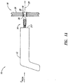
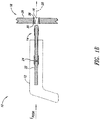
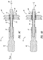
- Figures 1A and 1B show an installation system 10 having an installation tool 12 and a mandrel assembly 14 to cold expand an opening 16 in a structural workpiece 18 according to the illustrated embodiment.
- the mandrel assembly 14 is detachably coupled to the installation tool 12 and is operable to be initially pushed through the opening 16 in a first direction 20 with a limited amount of applied push-force "F PUSH .”
- the mandrel assembly 14 is then pulled through the opening 16 to expand the diameter of the opening 16.
- the installation tool 12 is a hydraulically actuated tool having an internal rod/piston arrangement that provides sufficient force to forcibly push and/or pull an outer member through the opening 16 of the structural workpiece 18.
- the installation tool 12 can include, without limitation, a puller (e.g., a hydraulic puller gun), a nosecap, an adapter, and other types of components used with installation tools.
- a rod 22 extending through the installation tool 12 is coupled to an adaptor 24.
- the adaptor 24 is integrally formed with or otherwise mechanically attached to the rod 22.
- the adaptor 24 operates like a keyed or keyless chuck for a drill.
- Installation tools 12 and adaptors 24 are known in the art and will not be described in further detail in the interest of brevity. At least one embodiment of an installation tool 12 that could be used with the mandrel assembly 14 is described in U.S. Patent No. 4,187,708 .
- the structural workpiece 18 is representative of any structure having an opening 16 formed therein.
- the structural workpiece 18 can include, but is not limited to, one or more composite materials (e.g., laminates, fiber reinforced composites, and the like), metal (e.g., steel, aluminum, titanium, and the like), polymers, plastics, and combinations thereof, as well as other types of materials suitable for being expanded.
- the structural workpiece 18 can be any type of structural component, for example, a panel, web, spar, rib, conduit fitting, bushing, grommet, sleeve, nut assembly for receiving a fastener, a sealing device for sealing the opening, and/or some other type of structure.
- the structural workpiece 18 is a fiber-reinforced composite panel 26 with a bushing assembly 27.
- the bushing assembly 27 includes an inner bushing 28 and an outer bushing 30 installed in the opening 16.
- the reference to the structural workpiece 18 in this exemplary embodiment can include the composite panel 26, the inner bushing 28, the outer bushing 30, or any combination of these or other components.
- the mandrel assembly 14 is used to radially expand the inner bushing 28 and/or outer bushing 30 into the panel 26.
- the structural workpiece 18, as illustrated is not meant to limit or otherwise narrow the disclosed embodiments.
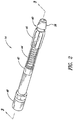
- Figures 2 and 3 show the mandrel assembly 14 having an inner elongated rod 40, a jam nut 42, an actuator 44, an expandable outer member 46, and a tool-coupling member 48 according to one illustrated embodiment.
- the illustrated actuator 44 is in the form of a biasing member.
- the inner rod 40 is coupled to the tool-coupling member 48.
- the jam nut 42 is closely received by the inner rod 40 according to one embodiment.
- the biasing member 44 and outer member 46 are disposed on the inner rod 40 between the jam nut 42 and a head section 58 of the inner rod 40.
- FIGS 3 , 4A, 4B, and 4C show various aspects of the inner rod 40.
- the inner rod 40 includes an engagement section 50, a first section 52 extending from the engagement section 50, a second section 54 extending from the first section 52, a contoured or expansion section 56 extending from the second section 54, and the head section 58 coupled to the contoured section 56.
- a shoulder 60 is formed between the contoured section 56 and the head section 58.
- the contoured section 56 of the inner rod 40 includes a first diameter 56a connected to a larger second diameter 56b.
- the contoured section 56 is uniformly tapered, according to the illustrated embodiment.
- the contoured section 56 includes a stepped profile where the diameter of the contoured section 56 is stepped down or up in size ( Figure 4C ).
- the contoured section 56 can have other configurations suitable for expanding the outer member 46 when the outer member is moved over the inner rod 40.
- the inner rod 40 is a monolithic part according to the illustrated embodiment.
- Figures 3 and 5 show the jam nut 42 having an inner diameter 62 and an outer diameter 64.
- the inner diameter 62 is sized to be closely received by at least a portion of the first section 52 of the inner rod 40.
- the jam nut 42 is press fit onto the first section 52 of the inner rod 40 to form an interference fit therewith. It is understood that other methods may be used to connect the jam nut 42 to the first section 52 of the inner rod 40. The amount of relative movement between the jam nut 42 and the inner rod 40 can be minimized, limited, or substantially prevented.
- the jam nut 42 provides a reaction force for the biasing member 44 acting against the outer member 46.
- the outer diameter 64 is sized relative to the inner diameter 62 (i.e., the thickness of the jam nut 42) so as to maintain the biasing member 44 on the inner rod 40.
- the outer diameter 64 can be sufficiently large to prevent the biasing member 44 from traveling over the outer diameter 64 of the jam nut 42 when the mandrel assembly 14 is in operation.
- the biasing member 44 is located between the jam nut 42 and the outer member 46.
- the biasing member 44 acts to exert a force on and/or absorb energy from the outer member 46.
- the biasing member 44 can include one or more springs (e.g., helical springs, conical springs, and the like).
- the biasing member 44 is a round-wire helical compression spring received by at least a portion of the second section 54 of the inner rod 40.
- the biasing member 44 comprises nested round-wire springs.
- Figures 2, 3, and 6A-6B show the outer member 46 according to one illustrated embodiment.
- Figure 6A shows the outer member 46 having a first end 66, a second end 68, an inner surface 70, a first tapered section 72, and a second tapered section 74.
- the first end 66 of the outer member 46 cooperates with the jam nut 42 to maintain the biasing member 44 therebetween as best seen in Figures 2 and 3 .
- the second end 68 engages the shoulder 60 of the head section 58 of the inner rod 40.
- the shoulder 60 of the inner rod 40 can limit movement of the outer member 46 in the first direction 20 ( Figure 1A ).
- the shoulder 60 serves as a stop that limits axial movement of the outer member 46 relative to the inner rod 40 when the inner rod 40 is pulled through the opening 16.
- the shoulder 60 can include, without limitation, one or more outwardly extending protrusions, flanges, or other structures suitable for limiting movement of the outer member 46 relative to the inner rod 40.
- the inner surface 70 of the outer member 46 is complementarily formed to be slideably received by the contoured section 56 of the inner rod 40.
- the inner surface 70 defines a passageway 71 ( Figure 6A ) that slightly increases in size from the first end 66 to the second end 68, according to the illustrated embodiment.
- the first tapered section 72 increases in thickness from the first end 66 to an intermediate region 78.
- the intermediate region 78 includes the maximum outer diameter for the outer member 46.
- the second tapered section 74 decreases in thickness from the intermediate region 78 to the second end 68.
- Figure 6B shows the outer member 46 with a plurality of longitudinal slots 82.
- the number of longitudinal slots 82 ranges from about 4-16 slots.
- the longitudinal slots 82 enable the outer member 46 to radially expand and contract as the outer member 46 moves relative to the rod 40 (e.g., onto or off of the contoured section 56 of the inner rod 40 ( Figure 3 )).
- the outer member 46 can be elastically expanded and contracted in order to perform a desired number of expansion processes.
- Such a reusable outer member 46 can cold work a desired number of work pieces resulting is less waste as compared to disposable one-time use sleeves.
- Each longitudinal slot 82 extends through the radial thickness of the outer member, but extends only partially through the longitudinal length "L" of the outer member 46.
- a first set of longitudinal slots 82a extends from the first end 66 toward the second end 68 of the outer member 46.
- a second set of longitudinal slots 82b extends from the second end 68 toward the first end 66 of the outer member 46.
- the outer member 46 includes eight (8) longitudinal slots 82, each slot having a width "W" in the range of about 0.011 inches to about 0.014 inches (0.2794 mm - 0.3556 mm). The length of the longitudinal slots 82 may be varied above or below the exemplary range depending on design objectives.
- the spacing "D1," the offset distance “D2,” the width "W”, the number of longitudinal slots 82, and the material (e.g., steel, tool steel, hardened steel, and the like) used to make the outer member 46 can be varied and/or changed to achieve a desired amount of radial and/or circumferential stiffness for the outer member 46 and/or to accommodate various degrees of taper for the contoured section 56 of the inner rod 40.
- the longitudinal slots 82 can be made by an electrical discharge machining (EDM) process or a similar process that is capable of achieving the desired design specifications of the outer member 46.
- Figure 7 shows the tool-coupling member 48 having a first section 84 and a second section 86.
- the first section 84 includes a passage 88 formed at least partially through the body of the tool-coupling member 48.
- the passage 88 is sized to closely receive the engagement section 50 of the inner rod 40, for example if the engagement section 50 is press fit into the passage 88.
- the passage 88 is internally threaded to receive the externally threaded engagement section 50 of the inner rod 40.
- the passage 88 has a polygonal shape, for example hexagonal or octagonal, to receive a complementary shaped engagement section 50 of the inner rod 40.
- the second section 86 of the tool-coupling member 48 is configured to be received either by the adaptor 24 ( Figure 1B ) or directly by the tool 12, for example if the adaptor 24 is integrally formed as part of the rod 22 of the tool 12.
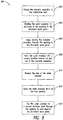
- FIG. 8 The flowchart of Figure 8 in cooperation with Figures 9A-9E describe and show a method 200 of using the mandrel assembly 14 to cold expand the opening 16 in the structural workpiece 18.
- the mandrel assembly 14 is coupled to the installation tool 12, either through the adaptor 24 or directly.
- the outer member 46 of the mandrel assembly 14 is placed in proximity to the opening 16 of the structural workpiece 18.
- the outer member 46 is located in a first position 90, which is generally when the second end 68 of the outer member 46 is adjacently positioned and/or in contact with the shoulder 60 of the head section 58 of the inner rod 40.
- the biasing member 44 can push the outer member 46 towards the shoulder 60 to keep the outer member 46 near or at the first position 90.
- the head section 58 of the inner rod 40 is inserted into the opening 16.
- the head section 58 is sized to be guided through the opening 16 without requiring a significant push force F PUSH .
- the second tapered section 74 of the outer member 46 can make contact with the structural workpiece 18.
- the outer member 46 is pressed against the structural workpiece 18.
- the push force F PUSH is greater than the biasing force of the biasing member 44, the outer member 46 moved over the inner rod 40 towards the jam nut 42.
- the push force F PUSH applied to the mandrel assembly 14 is reacted by the structural workpiece 18 until the outer member 46 is moved towards the second position 92 (illustrated near the jam nut 42).
- the outer member 46 is forced substantially off of the contoured section 56 of the inner rod 40 and fully into the second position 92.
- the biasing member 44 is compressed as at least some of the kinetic energy is absorbed by the biasing member 44 due to the axial displacement of the outer member 46.
- the outer diameter along each portion of the outer member 46 is radially reduced as the outer member 46 is forced towards the second position 92.
- the outer member 46 thus contracts radially inward about the rod 40 while it moves towards the second position 92.
- the longitudinal slots 82 formed in the outer member 46 allow the outer member 46 to expand and contract radially with the advantage of not causing plastic deformation, strain hardening of the mandrel material, and other unwanted damage to the mandrel assembly 14.
- the outer member 46 collapses inwardly towards the inner rod 40 until the outer member 46 passes through the opening 16 in the first direction 20.
- the dimensions (e.g., the outer diameter) of the outer member 46 can be selected to allow the outer member 46 to pass through openings of various sizes.
- the outer surface 211 of the outer member 46 can slide against an inner surface 215 of the opening 16.
- the frictional interaction between the outer member 46 can the inner surface 215 can be maintained at or below a desired level to limit or substantially prevent damage (e.g., striation marks, contact damage, and the like) to the inner surface 215 of the opening 16.
- the biasing member 44 forces the outer member 46 along the inner rod 40 back into the first position 90.
- the outer member 46 can expand outwardly from the collapsed configuration to the expanded configuration, wherein the diameter of the intermediate region 78 is greater than the diameter of the opening 16.
- the outer member 46 is now positioned between the shoulder 60 and a blind side 94 of the structural workpiece 18.
- the installation tool 12 is actuated to pull the mandrel assembly 14 in the second direction 96.
- An engagement face 217 of the installation system 10 can rest against the work piece 18 to generate sufficient axial force F PULL for the expansion process.
- F PULL axial force
- the maximum outer diameter of the intermediate region 78 of the outer member 46 contacts and expands the opening 16 of the structural workpiece 18, which may or may not include the bushings 28, 30.
- the radial expansion shown in Figure 9E is exaggerated for illustrative purposes. In actuality, the amount of radial expansion may amount to micro-inches and will likely not be perceivable by an unassisted human eye.
- mandrel assembly 14 can include a standard tool-coupling member 48 that can fit into a variety of adaptors and/or installation tools.
- mandrel assembly 14 Another possible advantage of the mandrel assembly 14 is that it can be used multiple times, unlike other mandrels used with disposable sleeve, such as a one-time use low-cost disposable sleeve made of non-tool steel.
- the mandrel assembly 14 can be used to cold expand an opening from only one side of the structural workpiece.
- Figures 10 to 16 illustrate mandrel assemblies that may be generally similar to the mandrel assembly 14 discussed in connection with Figures 1 to 9 .
- Figure 10 shows a mandrel assembly 300 having an inner elongated rod 302, a jam nut 304, a biasing member 306, and a outer member 308 according to the illustrated embodiment.
- the mandrel assembly 300 does not include a tool-coupling as in the previous embodiments, but instead is attachable directly to the installation tool 12.
- a tool-engagement portion 310 of the mandrel 300 is configured to threadably engage the installation tool 12.
- Figure 11 shows an alternate embodiment in which the tool-engagement portion 310 of the mandrel assembly 300 includes an engagement protuberance 312 for engaging either an adaptor or engaging the installation tool 12. It is understood that the tool-engagement portion 310 can take a variety of forms and can be engageable with the installation tool 12 in a variety of ways.
- the outer member 410 has an expandable portion 412 coupled to and extending from a backing 414.
- the expandable portion 412 is selectively moveable between an unexpanded low-profile configuration for passing through an opening in a workpiece and an expanded configuration for performing an expansion process.
- Figure 14 shows the expandable member 412 in an expanded configuration defining an increased maximum circumference.
- the expandable portion 412 is in the unexpanded low-profile configuration defining a reduced maximum circumference.
- the expandable portion 412 includes a first end 430, a second end 432, a main body 434 extending between the ends 430, 432, and a plurality of circumferentially spaced longitudinal slots 420.
- the slots 420 extend from the first end 430 along the main body 434 towards the second end 432.
- the illustrated expandable portion 412 includes four somewhat evenly spaced slots 420. In other embodiments, the expandable portion 412 includes a greater or lesser number of slots, which may be evenly or unevenly spaced from each other, based on the desired forces required to radially displace the expandable portion 412.
- the expandable portion 412 includes a thickened portion 490 defining the maximum circumference of the expandable portion 412.
- the thickened portion 490 engages an expandable or contoured section 460, the thickened portion 490 has a sloped outer surface 492 suitable for performing an expansion process.
- the slots 420 extend partially through the expandable portion 412 in the longitudinal direction.
- the axial lengths of the slots 420 are greater than the axial length of the expandable section 460, thereby permitting substantially elastic, resilient deformation of the expandable portion 412.
- the ends 421 of the slots 420 are in proximity to, but spaced from, the backing 414.
- the number, spacing, widths, and lengths of the slots 420 can be selected based on the desired force suitable for actuating the outer member 410 along the elongated rod 411.
- the backing 414 of Figure 13 is coupled to the second end 432 of the expandable portion 412 and extends radially outward to define a seating face 440 for engaging the biasing member 450.
- the illustrated backing 414 with a generally circular axial cross-section is integrally formed with the expandable portion 412. Other types of backings or structures can be used to engage the biasing member 450.
- the biasing member 450 can be directly or indirectly coupled to the second end 432 to the expandable portion 412. Welding, adhesives, fasteners, or other coupling means can be used to couple the biasing member 450 to the backing 414.
- the inner rod 411 includes the expansion section 460 that slidably engages at least a portion of an inner surface 470 of the outer member 410.
- the illustrated inner rod 411 also includes a transition section 480 extending between the contoured section 460 and a central body 462.
- the central body 462 can extend between the transition section 480 and an engagement section 464.
- the illustrated engagement section 464 is disposed within a tool-coupling member 466.
- Figure 16 shows a mandrel assembly 500 including a portion of an actuator 510 and an outer member 520 coupled to the actuator 510.
- the actuator 510 can be driven electrically, mechanically, pneumatically, hydraulically or by any other suitable drive means.
- the actuator 510 is a solenoid that is activated to move the outer member 520 from the second position to the first position in the direction indicated by the arrow 530.
- the actuator 510 is a pneumatically driven piston, such as a linearly reciprocating piston.
- the type and configuration of the actuator 510 can be selected to achieve the desired forces (e.g., pushing forces, pulling forces, torques, or combinations thereof) on the outer member 520.
- the outer members described herein can be moved along the inner rods manually or by an actuating device attached to the workpiece.
- One of ordinary skill in the art can select the appropriate means for moving the outer member based on the process to be performed.
Applications Claiming Priority (2)
| Application Number | Priority Date | Filing Date | Title |
|---|---|---|---|
| US75473805P | 2005-12-28 | 2005-12-28 | |
| EP06027027.9A EP1803526B1 (de) | 2005-12-28 | 2006-12-28 | Dorneinheit und Verfahren zu ihrer Verwendung |
Related Parent Applications (1)
| Application Number | Title | Priority Date | Filing Date |
|---|---|---|---|
| EP06027027.9A Division EP1803526B1 (de) | 2005-12-28 | 2006-12-28 | Dorneinheit und Verfahren zu ihrer Verwendung |
Publications (2)
| Publication Number | Publication Date |
|---|---|
| EP3199292A1 true EP3199292A1 (de) | 2017-08-02 |
| EP3199292B1 EP3199292B1 (de) | 2020-03-11 |
Family
ID=37714649
Family Applications (2)
| Application Number | Title | Priority Date | Filing Date |
|---|---|---|---|
| EP17159895.6A Active EP3199292B1 (de) | 2005-12-28 | 2006-12-28 | Dorneinheit und verfahren zu ihrer verwendung |
| EP06027027.9A Active EP1803526B1 (de) | 2005-12-28 | 2006-12-28 | Dorneinheit und Verfahren zu ihrer Verwendung |
Family Applications After (1)
| Application Number | Title | Priority Date | Filing Date |
|---|---|---|---|
| EP06027027.9A Active EP1803526B1 (de) | 2005-12-28 | 2006-12-28 | Dorneinheit und Verfahren zu ihrer Verwendung |
Country Status (2)
| Country | Link |
|---|---|
| US (3) | US7509829B2 (de) |
| EP (2) | EP3199292B1 (de) |
Families Citing this family (41)
| Publication number | Priority date | Publication date | Assignee | Title |
|---|---|---|---|---|
| US20070110541A1 (en) * | 2005-10-28 | 2007-05-17 | Fatigue Technology, Inc. | Radially displaceable bushing for retaining a member relative to a structural workpiece |
| US7509829B2 (en) * | 2005-12-28 | 2009-03-31 | Fatigue Technology, Inc. | Mandrel assembly and method of using the same |
| US8568034B2 (en) * | 2006-01-11 | 2013-10-29 | Fatigue Technology, Inc. | Bushing kits, bearings, and methods of installation |
| CA2535577C (en) * | 2006-02-08 | 2013-08-13 | Nav-Aids Ltee | Test adapter for aircraft static vent |
| DE102006019405B4 (de) | 2006-04-24 | 2011-08-18 | EADS Deutschland GmbH, 85521 | Werkzeug zur Kaltexpansion von Löchern |
| WO2007127430A2 (en) | 2006-04-27 | 2007-11-08 | Fatigue Technology, Inc. | Alignment device and methods of using the same |
| WO2007127399A2 (en) * | 2006-04-27 | 2007-11-08 | Fatigue Technology, Inc. | Wave relieving geometric features in structural members that are radially expandable into workpieces |
| EP1872895B1 (de) * | 2006-06-29 | 2012-12-12 | Fatigue Technology, Inc. | Selbstausrichtende Werkzeuge und Dorn mit Haltebuchse |
| WO2008027408A1 (en) | 2006-08-28 | 2008-03-06 | Fatigue Technology, Inc. | Installation/processing systems and methods of using the same |
| US8312606B2 (en) * | 2007-10-16 | 2012-11-20 | Fatigue Technology, Inc. | Expandable fastener assembly with deformed collar |
| US10010983B2 (en) | 2008-03-07 | 2018-07-03 | Fatigue Technology, Inc. | Expandable member with wave inhibitor and methods of using the same |
| EP2318726B1 (de) | 2008-07-18 | 2015-09-02 | Fatigue Technology, Inc. | Annietmutteranordnung und verwendungsverfahren dafür |
| US8636455B2 (en) | 2009-04-10 | 2014-01-28 | Fatigue Technoloy, Inc. | Installable assembly having an expandable outer member and a fastener with a mandrel |
| EP2513499B1 (de) | 2009-12-16 | 2015-04-08 | Fatigue Technology, Inc. | Modularer mutternhalter und verfahren zu seiner anwendung |
| CN102205488A (zh) * | 2010-03-31 | 2011-10-05 | 中国商用飞机有限责任公司 | 一种开缝衬套冷挤压加工孔的方法 |
| WO2012167136A2 (en) | 2011-06-03 | 2012-12-06 | Fatigue Technology, Inc. | Expandable crack inhibitors and methods of using the same |
| WO2012174215A2 (en) | 2011-06-15 | 2012-12-20 | Fatigue Technology, Inc | Modular nut plates with closed nut assemblies |
| GB201116287D0 (en) * | 2011-09-21 | 2011-11-02 | Airbus Operations Ltd | Method and device for removing a sleeve from a bore |
| US20130075150A1 (en) * | 2011-09-27 | 2013-03-28 | Christopher L. Newbolt | Bushing for use in providing electromagnetic effects protection |
| US9108363B2 (en) * | 2011-10-06 | 2015-08-18 | The Boeing Company | Thin wall bushing for robust electrical bonding to fiber-reinforced structures |
| EP2809482B1 (de) | 2012-01-30 | 2018-11-07 | Fatigue Technology, Inc. | Verarbeitungssystem und betriebsverfahren dafür |
| US20150035215A1 (en) * | 2013-08-05 | 2015-02-05 | Jon Baklund | Fixture system |
| DE102014208891B3 (de) * | 2014-05-12 | 2015-09-24 | Continental Automotive Gmbh | Druckbegrenzungsventil und Bauteil für ein Kraftstoffeinspritzsystem sowie Verfahren zur Herstellung eines Druckbegrenzungsventils |
| US9624996B2 (en) * | 2015-01-15 | 2017-04-18 | Flowco Production Solutions, LLC | Robust bumper spring assembly |
| CA2918007C (en) | 2015-01-15 | 2022-10-18 | Flowco Production Solutions, LLC | Robust bumper spring assembly |
| US10669824B2 (en) | 2015-02-20 | 2020-06-02 | Flowco Production Solutions, LLC | Unibody bypass plunger and valve cage with sealable ports |
| CA2921175C (en) * | 2015-02-20 | 2023-09-26 | Flowco Production Solutions, LLC | Improved dart valves for bypass plungers |
| US11578570B2 (en) * | 2015-02-20 | 2023-02-14 | Flowco Production Solutions, LLC | Unibody bypass plunger and valve cage with sealable ports |
| US9963957B2 (en) * | 2015-02-20 | 2018-05-08 | Flowco Production Solutions, LLC | Clutch assembly for bypass plungers |
| US10221849B2 (en) | 2015-05-18 | 2019-03-05 | Patriot Artificial Lift, LLC | Forged flange lubricator |
| CN105499385A (zh) * | 2015-12-04 | 2016-04-20 | 重庆长安空港汽车配件有限责任公司 | 一种管端成型机及其冲头 |
| US10161230B2 (en) | 2016-03-15 | 2018-12-25 | Patriot Artificial Lift, LLC | Well plunger systems |
| CN106955940B (zh) * | 2017-05-24 | 2019-04-23 | 宁波嘉天汽车管件有限公司 | 汽车管件端口成型设备及其端口成型方法 |
| US10550674B2 (en) | 2018-03-06 | 2020-02-04 | Flowco Production Solutions, LLC | Internal valve plunger |
| US20220056785A1 (en) * | 2018-09-13 | 2022-02-24 | Flowco Production Solutions, LLC | Unibody bypass plunger with integral dart valve cage |
| US11293267B2 (en) | 2018-11-30 | 2022-04-05 | Flowco Production Solutions, LLC | Apparatuses and methods for scraping |
| USD937982S1 (en) | 2019-05-29 | 2021-12-07 | Flowco Production Solutions, LLC | Apparatus for a plunger system |
| WO2021046330A1 (en) | 2019-09-05 | 2021-03-11 | Flowco Productions Solutions, Llc | Gas assisted plunger lift control system and method |
| EP4008482B1 (de) * | 2020-12-07 | 2023-10-11 | Dubuis et Cie | Fügewerkzeug zum verbinden eines verformbaren elements mit einem werkstück |
| CN113399486B (zh) * | 2021-06-17 | 2022-04-22 | 西北工业大学 | 一种多段式冷挤压强化装置及使用方法 |
| US11732557B2 (en) * | 2021-08-11 | 2023-08-22 | Liberty Lift Solutions, LLC | Bumper spring |
Citations (15)
| Publication number | Priority date | Publication date | Assignee | Title |
|---|---|---|---|---|
| US2275451A (en) * | 1939-05-20 | 1942-03-10 | Babcock & Wilcox Co | Method of producing pressure tight tube and tube-seat connections |
| US3358492A (en) * | 1965-09-08 | 1967-12-19 | Embassy Ind Inc | Mandrel construction |
| US3566662A (en) | 1969-04-28 | 1971-03-02 | Boeing Co | Coldworking method and apparatus |
| DE2203217A1 (de) * | 1972-01-24 | 1973-07-26 | Honsel Nieten & Metallwarenfab | Setzwerkzeug fuer blindnietmuttern |
| US3892121A (en) | 1973-09-12 | 1975-07-01 | Boeing Co | Apparatus for cold-working holes |
| US4187708A (en) | 1977-04-11 | 1980-02-12 | Industrial Wire & Metal Forming, Inc. | Pulling apparatus and method |
| WO1984000120A1 (en) * | 1982-07-01 | 1984-01-19 | Rast Patent Mfg Pty | Tube expander |
| US4471643A (en) | 1982-02-10 | 1984-09-18 | Fatigue Technology, Inc. | Method and apparatus for prestressing fastener holes |
| JPS60238046A (ja) * | 1984-05-10 | 1985-11-26 | Nippon Alum Mfg Co Ltd:The | パイプ拡管装置 |
| US4557033A (en) | 1983-07-11 | 1985-12-10 | Fatigue Technology, Inc. | Method of cold expanding and sizing fastener holes |
| US4597282A (en) * | 1983-01-14 | 1986-07-01 | West Coast Industries, Inc. | Method and apparatus for coldworking holes |
| DE3545554A1 (de) * | 1985-12-21 | 1987-07-02 | Sueddeutsche Kuehler Behr | Rohr-boden-verbindung, insbesondere fuer waermetauscher |
| US4779445A (en) * | 1987-09-24 | 1988-10-25 | Foster Wheeler Energy Corporation | Sleeve to tube expander device |
| US5083363A (en) | 1990-07-25 | 1992-01-28 | Fatigue Technology, Inc. | Method of installing a grommet in a wall of composite material |
| US6266991B1 (en) * | 2000-04-03 | 2001-07-31 | Albert S. Kuo | Coldwork holes with reusable seamless SMA sleeve |
Family Cites Families (185)
| Publication number | Priority date | Publication date | Assignee | Title |
|---|---|---|---|---|
| GB593607A (en) | 1945-06-08 | 1947-10-21 | Arthur Buescher | Improvements in arbors |
| US295593A (en) | 1884-03-25 | Jambs f | ||
| US810430A (en) | 1904-02-11 | 1906-01-23 | Frank Pfluger | Bung-hole bushing. |
| US1081496A (en) | 1908-03-23 | 1913-12-16 | Horatio G Gillmor | Expander for pipes, tubes, &c. |
| US1106964A (en) | 1913-07-07 | 1914-08-11 | Martin A Pahler | Signal-cord bushing. |
| US1226090A (en) | 1917-03-31 | 1917-05-15 | Nat Bush Company | Bushing for bungs. |
| US1297142A (en) | 1918-07-19 | 1919-03-11 | William J Gibbons | Bushing-blank and process of making bushings. |
| US1480298A (en) | 1922-10-14 | 1924-01-08 | George A Pearson | Bezel |
| GB348631A (en) | 1929-11-13 | 1931-05-13 | Hall & Kay Ltd | Improvements in or relating to metal sockets, bushes, ferrules, rivets and the like |
| US1881867A (en) | 1930-09-22 | 1932-10-11 | Vilter Mfg Co | Method of attaching annular elements to supporting structures |
| US2092358A (en) | 1935-02-18 | 1937-09-07 | Robertson John Hogg | Tubular joint |
| US2150361A (en) | 1935-05-20 | 1939-03-14 | Chobert Jacques Franco Gabriel | Method of and apparatus for securing hollow bodies in holes in other bodies |
| US2146461A (en) | 1937-01-06 | 1939-02-07 | Aviat Developments Ltd | Method of riveting |
| US2188596A (en) | 1939-05-05 | 1940-01-30 | Universal Clay Products Co | Removable bushing |
| US2357123A (en) | 1939-05-20 | 1944-08-29 | Babcock & Wilcox Co | Apparatus for producing pressure-tight tube and tube seat connections |
| US2405399A (en) | 1943-09-22 | 1946-08-06 | Bugg | Tube beading and expanding tool and method |
| US2468985A (en) | 1943-11-26 | 1949-05-03 | Goodrich Co B F | Resilient connection and method of making same |
| US2385294A (en) | 1944-06-17 | 1945-09-18 | New York Engineering Company | Bung bushing |
| US2430554A (en) * | 1944-06-21 | 1947-11-11 | Bugg | Tool for beading and flaring tubes |
| US2433425A (en) | 1945-03-20 | 1947-12-30 | Aero Coupling Corp | Fabricated high-pressure coupling |
| US2528180A (en) | 1946-03-02 | 1950-10-31 | William J Roehl | Pipe clamp |
| US2608751A (en) | 1946-04-15 | 1952-09-02 | Silentbloc | Method of assembling resilient bearings |
| US2583719A (en) | 1946-05-10 | 1952-01-29 | Weatherhead Co | Grommet |
| US2661182A (en) | 1948-02-02 | 1953-12-01 | Samuel M Kipp | Multiway piston valve with removable bushing and packing structure |
| US2695446A (en) | 1950-06-30 | 1954-11-30 | Metallschlauchfabrik Ag | Method of making tube-to-flange connection |
| US2700172A (en) | 1952-01-28 | 1955-01-25 | Frederick W Rohe | Sectional grommet for reinforcing openings in panels and sheets |
| US2672175A (en) | 1952-06-03 | 1954-03-16 | Russell B Howard | Pipe expander |
| US2808643A (en) | 1954-07-13 | 1957-10-08 | Weatherhead Co | Method of fabricating hose coupling members |
| US2943667A (en) | 1957-10-14 | 1960-07-05 | Arrowsmith Tool & Die Corp | Expanding mandrel hydro-press |
| US3164054A (en) | 1962-04-13 | 1965-01-05 | Illinois Tool Works | Bushing with rib and shoulder means |
| US3149860A (en) | 1961-01-16 | 1964-09-22 | Boeing Co | High pressure, high temperature reconnectible tube fitting |
| US3137887A (en) | 1962-06-15 | 1964-06-23 | Republic Aviat Corp | Bushing |
| US3128999A (en) | 1962-09-17 | 1964-04-14 | Lord Mfg Co | Resilient mounting |
| US3345730A (en) | 1963-10-16 | 1967-10-10 | Murray Mfg Corp | Apparatus for affixing a flange to a tube |
| US3244034A (en) | 1963-11-19 | 1966-04-05 | Anton M Severdia | Locking and retaining slip removable bushings |
| US3252493A (en) | 1964-05-22 | 1966-05-24 | Gen Dynamics Corp | Three part fastener with spacer means |
| US3434746A (en) | 1966-08-10 | 1969-03-25 | Amp Inc | Flexible tube coupling |
| US3399435A (en) | 1966-12-28 | 1968-09-03 | United Shoe Machinery Corp | Grommet assembly |
| US3537163A (en) | 1968-04-30 | 1970-11-03 | Robert H Steidl | Method of installing a cylindrical element into a cylindrical bore |
| US3498648A (en) | 1968-08-22 | 1970-03-03 | Boeing Co | High temperature and pressure tube fitting |
| US3693247A (en) | 1968-10-03 | 1972-09-26 | Clarence K Brown | Method of securing together a plurality of structural members |
| GB1323873A (en) | 1969-07-28 | 1973-07-18 | Avdel Ltd | Tubular rivet |
| US3674292A (en) | 1969-10-15 | 1972-07-04 | Amp Inc | Tubular connection devices |
| US3677684A (en) | 1969-12-15 | 1972-07-18 | Nat Distillers Chem Corp | Apparatus for enlarging an extremity of a plastic pipe |
| US3695324A (en) | 1970-01-09 | 1972-10-03 | Deutsch Fastener Corp | Floating nut assembly |
| US3601771A (en) | 1970-03-23 | 1971-08-24 | Us Terminals Inc | Electrical components with chamfered mounting rings |
| US3835525A (en) | 1970-04-30 | 1974-09-17 | J King | Method of fabricating a joint |
| GB1395009A (en) | 1971-05-26 | 1975-05-21 | Warner Son Engs Ltd Ray | Device for use in collapsible tube manufacture |
| US3778090A (en) | 1972-05-18 | 1973-12-11 | Gen Motors Corp | Beaded tube with o-ring seal connection |
| US3820297A (en) | 1972-11-10 | 1974-06-28 | Huck Mfg Co | Interference fit blind fastener |
| US3763541A (en) | 1972-11-30 | 1973-10-09 | D Jaffe | Method of and apparatus for setting blind fasteners |
| US4164807A (en) | 1974-03-19 | 1979-08-21 | King John O Jun | Method of forming a coldworked joint |
| US3943748A (en) | 1973-01-17 | 1976-03-16 | King John O Jun | Coldwork system with delay split sleeve |
| US3875649A (en) | 1973-01-17 | 1975-04-08 | King John O Jun | Coldworking method and apparatus with frangible head flange |
| US3949535A (en) | 1973-01-17 | 1976-04-13 | King John O Jun | Coldworked joint held by seamless tubular member |
| US3787945A (en) | 1973-05-14 | 1974-01-29 | Gen Motors Corp | Method of fabricating an expanded tube connection |
| GB1469406A (en) | 1973-05-29 | 1977-04-06 | Automatic Fastener Corp | Fastener setting apparatus |
| US3895409A (en) | 1973-08-31 | 1975-07-22 | Johns Manville | Spacer grommet and method of manufacture thereof |
| SE407451B (sv) | 1973-12-10 | 1979-03-26 | Kubota Ltd | Forbindningsorgan for ror |
| US3915052A (en) | 1974-08-22 | 1975-10-28 | Huck Mfg Co | Self broaching fastener assembly and like self sizing fasteners |
| GB1548880A (en) | 1975-07-23 | 1979-07-18 | Tucker Fasteners Ltd | Blind riveting |
| US4237768A (en) | 1976-11-05 | 1980-12-09 | Hi-Shear Corporation | Blind fastener |
| US4143580A (en) | 1976-12-20 | 1979-03-13 | Allfast, Inc. | Lock spindle blind rivet |
| SU632463A1 (ru) | 1977-04-05 | 1978-11-15 | Предприятие П/Я А-1264 | Устройство дл клепки клиновидных пакетов |
| US4249786A (en) | 1978-11-03 | 1981-02-10 | Hydraflow Supply, Inc. | Flexible coupling |
| JPS6024169Y2 (ja) | 1980-02-29 | 1985-07-19 | ワイケイケイ株式会社 | 鳩目 |
| EP0054592A1 (de) | 1980-12-23 | 1982-06-30 | Incom International Inc. | Verfahren zur Herstellung sphärischer Lager |
| US4355612A (en) | 1981-02-06 | 1982-10-26 | Outboard Marine Corporation | Cooling system with removable valve member |
| US4405256A (en) | 1981-04-14 | 1983-09-20 | King John O Jun | Cushioned fastener joint |
| SE450660B (sv) | 1981-04-21 | 1987-07-13 | Reheat Ab | Forfarande for fodring av fluidumanslutningsoppning i en stativplatta till plattvermevexlare |
| US4423619A (en) | 1981-06-15 | 1984-01-03 | Fatigue Technology, Inc. | Apparatus and method for prestressing a countersunk fastener hole |
| CA1199353A (en) | 1981-09-21 | 1986-01-14 | Boart International Limited | Connection of drill tubes |
| US4386515A (en) * | 1981-12-30 | 1983-06-07 | Usm Corporation | Setting tool for blind fasteners |
| US4524600A (en) | 1982-02-10 | 1985-06-25 | Champoux Robert L | Apparatus for prestressing fastener holes |
| US4425780A (en) | 1982-02-10 | 1984-01-17 | Fatigue Technology, Inc. | Apparatus having extended prestressing and sleeve retaining devices for prestressing countersunk fastener holes and method |
| US4491358A (en) | 1982-04-21 | 1985-01-01 | Edison International, Inc. | Clamp |
| US4447944A (en) | 1982-06-16 | 1984-05-15 | The United States Of America As Represented By The Secretary Of The Navy | Method of forming a tubular rivet in fastening relation to a plurality of laminates |
| SE456856B (sv) | 1982-06-18 | 1988-11-07 | Alfa Laval Thermal Ab | Plattvaermevaexlare och saett att infodra en anslutningsport i denna |
| DE3301849C1 (de) | 1983-01-20 | 1984-07-12 | MTG Montagetechnik Peter Ernst GmbH, 5758 Fröndenberg | Klemmblindniet |
| US4640479A (en) | 1983-01-31 | 1987-02-03 | All States Inc. | Strain relief grommet |
| US4494398A (en) * | 1983-02-14 | 1985-01-22 | Midas International Corporation | Tubing expander apparatus |
| GB8322719D0 (en) | 1983-08-24 | 1983-09-28 | Adaptaflex Ltd | End fittings for flexible conduits |
| US4665732A (en) * | 1983-09-30 | 1987-05-19 | West Coast Industries, Inc. | Method and apparatus for hole coldworking |
| US4583388A (en) | 1983-09-30 | 1986-04-22 | West Coast Industries, Inc. | Method and apparatus for hole coldworking |
| US4522378A (en) | 1983-11-02 | 1985-06-11 | Illinois Tool Works, Inc. | Wiper motor mounting grommet |
| DE3531532A1 (de) * | 1985-09-04 | 1987-03-12 | Peter Potzas | Verfahren und vorrichtung zum setzen von blindnieten |
| US4755904A (en) | 1986-06-06 | 1988-07-05 | The Boeing Company | Lightning protection system for conductive composite material structure |
| US4759237A (en) | 1986-12-18 | 1988-07-26 | Fauchet Christian R | Self-locking nut and tightening tool |
| US4787793A (en) | 1987-03-27 | 1988-11-29 | Terrell Lee Sharp | Bolt guard |
| US4905766A (en) | 1987-04-28 | 1990-03-06 | R&G Sloane Mfg. Co., Inc. | Adapter for plastic pipe |
| US4809420A (en) | 1987-12-16 | 1989-03-07 | Fatigue Technology, Inc. | Method and apparatus for backing up mandrel exit holes in knuckle structures |
| IT1215911B (it) | 1988-02-18 | 1990-02-22 | Cembre Srl | Contatto elettrico permanente applicabile sull'anima di rotaie esimili. |
| US4869091A (en) * | 1988-03-22 | 1989-09-26 | The Boeing Company | Tool for coldworking holes |
| US4985979A (en) | 1989-01-23 | 1991-01-22 | Mcdonnell Douglas Corporation | Method of installing interference fit sleeved fasteners having radiused intersection for stress coining |
| US4885829A (en) | 1989-02-16 | 1989-12-12 | Fatigue Technology, Incorporated | Fatigue life enhancement of dovetail connector slots and noncircular openings |
| US4934170A (en) | 1989-02-16 | 1990-06-19 | Fatigue Technology, Incorporated | Fatigue life enhancement of noncircular openings |
| FR2645052B1 (fr) | 1989-03-31 | 1996-07-26 | Virax Sa | Perfectionnements aux outils d'expansion se montant sur un appareil a faconner les extremites des tubes |
| US5088194A (en) | 1989-04-10 | 1992-02-18 | Lasko John A | Fluid distribution system, and apparatus and method for making same |
| US4934038A (en) * | 1989-09-15 | 1990-06-19 | Caterpillar Inc. | Method and apparatus for tube expansion |
| US4999896A (en) | 1989-10-25 | 1991-03-19 | Gemcor Engineering Corporation | Automatic double-flush riveting |
| US5038596A (en) | 1989-12-01 | 1991-08-13 | Grumman Aerospace Corporation | Threaded cold working mandrel |
| GB2239917B (en) | 1990-01-15 | 1993-09-29 | Fischer George Castings Ltd | An adaptor fitting |
| US5129253A (en) | 1990-01-26 | 1992-07-14 | Bell Helicopter Textron Inc. | Antifretting coating for a bushing in a coldworked joint |
| US5110163A (en) | 1990-03-22 | 1992-05-05 | Lokring Corporation | Pipe fitting with improved coupling body |
| US5405228A (en) | 1990-07-26 | 1995-04-11 | Fatigue Technology, Inc. | Nut cage and mount |
| US5245743A (en) | 1990-07-26 | 1993-09-21 | Fatigue Technology, Inc. | Method of installing a nut mounting grommet |
| US5096349A (en) | 1990-07-26 | 1992-03-17 | Fatigue Technology, Inc. | Nut mounting grommet |
| US5069586A (en) | 1990-08-27 | 1991-12-03 | Casey Marion B | Self-locking two-part grommet |
| US5103548A (en) | 1991-05-13 | 1992-04-14 | Fatigue Technology, Inc. | Method and apparatus for securing a tubular bushing in a circular opening |
| US5093957A (en) | 1991-07-08 | 1992-03-10 | Atr International, Inc. | Compression fitting for use in a two-sided honeycomb panel |
| US5127254A (en) | 1991-07-10 | 1992-07-07 | Fatigue Technology, Inc. | Method and apparatus for split sleeve cold expansion of openings in structural members |
| US5305627A (en) | 1992-07-27 | 1994-04-26 | Fatigue Technology, Inc. | Split sleeve cold expansion |
| US5218854A (en) | 1992-05-08 | 1993-06-15 | Fatigue Technology, Inc. | System for cold expanding holes in rail sections |
| US5253773A (en) | 1992-08-26 | 1993-10-19 | General Signal Corporation | Filler tube for liquid containers |
| DE4301124C2 (de) | 1993-01-18 | 1996-10-17 | Danfoss As | Verfahren zum Verbinden einer Zylinderbuchse mit einem Grundkörper |
| US5341559A (en) | 1993-04-13 | 1994-08-30 | Fatigue Technology, Inc. | Method and apparatus for securing a tubular bushing in a circular opening |
| IL106286A (en) | 1993-07-07 | 1996-05-14 | Israel State | Surface connector |
| US5380136A (en) | 1993-09-14 | 1995-01-10 | Fatigue Technology, Inc. | Anchor nut mount |
| US5433100A (en) | 1993-11-12 | 1995-07-18 | Fatigue Technology, Inc. | Apparatus for split sleeve and tubular bushing cold expansion |
| DE4343171C2 (de) | 1993-12-17 | 1996-08-08 | Gesipa Blindniettechnik | Blindniet und Verfahren zu seiner Herstellung |
| US5380111A (en) | 1993-12-20 | 1995-01-10 | Westrom; S. John | Releasable spacer assembly for binders |
| BR9401280A (pt) | 1994-03-24 | 1994-10-11 | Helio Lanfranchi Seabra | Aperfeiçoamento aplicado em processo de travamento de conexão giratória. |
| US5466016A (en) | 1994-04-11 | 1995-11-14 | General Motors Corporation | Solderless filler neck joint |
| US5468104A (en) | 1994-08-10 | 1995-11-21 | Fatigue Technology, Inc. | Wall nut assembly |
| JP3186492B2 (ja) | 1995-02-17 | 2001-07-11 | 田中貴金属工業株式会社 | ブッシングベースプレート及びその製造方法 |
| JP3972961B2 (ja) | 1995-03-10 | 2007-09-05 | 新日本石油株式会社 | 揺動型アクチュエータ及びその製造方法 |
| US5607194A (en) | 1995-04-20 | 1997-03-04 | Universal Enterprises, Inc. | Member and tube assembly |
| US5806173A (en) | 1995-07-28 | 1998-09-15 | Hidaka Seiki Kabushiki Kaisha | Tube expander |
| JPH0979033A (ja) | 1995-09-13 | 1997-03-25 | Sango Co Ltd | 管部材と板体の接合構造及び接合方法並びに前記接合構造を有する消音器 |
| US6183180B1 (en) | 1996-01-19 | 2001-02-06 | Fatigue Technology, Inc. | Wall nut and bolt assemblies |
| JP3175647B2 (ja) | 1997-07-04 | 2001-06-11 | 住友電装株式会社 | グロメット |
| USRE38788E1 (en) | 1997-07-04 | 2005-09-06 | Sumitomo Wiring Systems, Ltd. | Grommet |
| DE29712206U1 (de) | 1997-07-11 | 1997-08-28 | Kabelkonfektionstechnik Kkt Gm | Vorrichtung zum Anschluß einer elektrischen Leitung an einem Eisenbahnschienensteg o.dgl. |
| US5947326A (en) | 1997-11-12 | 1999-09-07 | Alasco Rubber & Plastics Corporation | Bung and stopper |
| US5943898A (en) | 1998-02-17 | 1999-08-31 | Kuo; Albert S. | Method and apparatus to coldwork holes |
| DE59813339D1 (de) | 1998-03-22 | 2006-04-06 | Cembre Gmbh | Verfahren zur Herstellung eines elektrischen Dauerkontaktes am Steg einer Eisenbahnschiene und mit dem Verfahren hergestellter elektrischer Dauerkontakt |
| US6171038B1 (en) | 1998-11-12 | 2001-01-09 | Textron Inc. | Tapered shank rivet |
| US6131964A (en) | 1998-12-15 | 2000-10-17 | Westinghouse Air Brake Company | SAS fitting for tube and pipe connections |
| GB2344864A (en) | 1998-12-17 | 2000-06-21 | Textron Fastening Syst Ltd | Blind fastener |
| JP3490927B2 (ja) | 1999-05-19 | 2004-01-26 | ニチアス株式会社 | 熱遮蔽板に振動フローティングワッシャを取付ける方法 |
| DE19935246B4 (de) | 1999-06-04 | 2004-07-22 | Friatec Ag | Steckverbinder |
| US6077010A (en) | 1999-06-16 | 2000-06-20 | Fatigue Technology, Inc. | Wall bolt assembly |
| US6226991B1 (en) | 1999-08-16 | 2001-05-08 | Globe Technologies Corporation | Thermally sensitive actuating device |
| US6217082B1 (en) | 1999-09-09 | 2001-04-17 | Dana Corporation | Swivel fitting |
| GB2358053B (en) | 1999-12-14 | 2003-11-19 | Textron Fastening Syst Ltd | Insert and method of installation thereof |
| US6347663B1 (en) | 2000-03-13 | 2002-02-19 | Modine Manufacturing Company | Fitting/manifold assembly and method for a heat exchanger |
| US6487767B1 (en) | 2000-04-10 | 2002-12-03 | Fatigue Technology, Inc. | Method and apparatus for connecting a fastener element to a wall |
| US6488460B1 (en) | 2000-05-02 | 2002-12-03 | Bell Helicopter Textron Inc. | Composite panel insert with hold out recess feature |
| US7375277B1 (en) | 2000-06-26 | 2008-05-20 | Fatigue Technology, Inc. | Double flanged bushings and installation methods |
| US6325582B1 (en) | 2000-07-06 | 2001-12-04 | Huck International, Inc. | Swage type fastener with low swage load |
| US8155256B2 (en) | 2000-10-23 | 2012-04-10 | Texas Instruments Incorporated | Method and apparatus for asynchronous clock retiming |
| GB2371344A (en) | 2001-01-23 | 2002-07-24 | Frederick Arthur Summerlin | Blind rivet |
| US6705251B2 (en) | 2001-02-09 | 2004-03-16 | Ctb Ip, Inc. | Method for enhancing poultry production |
| US6623048B2 (en) | 2001-05-17 | 2003-09-23 | Delphi Technologies, Inc. | Apparatus and method of attaching a tube member to a housing of a vacuum brake booster |
| US6499926B2 (en) | 2001-05-18 | 2002-12-31 | The Boeing Company | Fastener apparatus and method of fastening non-metallic structures |
| US6705149B2 (en) | 2001-05-25 | 2004-03-16 | Huck Patents, Inc. | Universal backup mandrel with retractable sleeve and shock absorbing means |
| US7059816B2 (en) | 2001-11-09 | 2006-06-13 | Textron Inc. | Nut plate |
| US20030110618A1 (en) | 2001-12-14 | 2003-06-19 | Magnuson James M. | Multi-task steel process device |
| US6796765B2 (en) | 2001-12-27 | 2004-09-28 | General Electric Company | Methods and apparatus for assembling gas turbine engine struts |
| US6761380B2 (en) | 2002-05-07 | 2004-07-13 | Delphi Technologies, Inc. | Filler neck assembly for fuel tank |
| US6651301B1 (en) | 2002-06-28 | 2003-11-25 | Yang-Ting Liu | Adjustable hand tool with dual functions |
| EP1616107B1 (de) | 2003-04-23 | 2007-02-07 | Glacier Garlock Bearings, Inc. | Verbundlager |
| BRPI0409305A (pt) | 2003-05-14 | 2006-04-11 | Textron Fastening Syst Ltd | fixador cego para inserção em uma abertura em uma peça de trabalho, e, método de remover um fixador de uma peça de trabalho |
| US7024908B2 (en) | 2003-07-10 | 2006-04-11 | Fatigue Technology, Inc. | Fatigue enhancement of material surrounding openings in workpieces |
| US7448652B2 (en) | 2003-07-31 | 2008-11-11 | Fatigue Technology Inc. | Tubular metal fitting expandable in a wall opening and method of installation |
| US7024909B2 (en) * | 2003-10-21 | 2006-04-11 | Alcoa Global Fasteners, Inc. | Non-impact swaging apparatus |
| US7325796B2 (en) | 2003-12-01 | 2008-02-05 | Moreland Charles E | Polymer and rigid suspension bearing assembly for motor vehicles |
| US7047596B2 (en) | 2003-12-09 | 2006-05-23 | Sikorsky Aircraft Corp. | Structural bushing application for highly loaded composites lugs |
| ATE402346T1 (de) | 2004-04-15 | 2008-08-15 | Fatigue Technology Inc | Verfahren und vorrichtung unter einsatz von exzenterbuchsen |
| US7464577B2 (en) | 2004-07-01 | 2008-12-16 | General Electric Company | Method for fabricating rotary machines |
| US8057144B2 (en) | 2004-08-27 | 2011-11-15 | Fatigue Technology, Inc. | Sealed, blind fastener assembly |
| EP1893875B1 (de) | 2005-06-03 | 2011-03-02 | Fatigue Technology, Inc. | Befestigungseinrichtung und Verfahren zum Zusammensetzen derselben |
| US20070110541A1 (en) | 2005-10-28 | 2007-05-17 | Fatigue Technology, Inc. | Radially displaceable bushing for retaining a member relative to a structural workpiece |
| US7509829B2 (en) * | 2005-12-28 | 2009-03-31 | Fatigue Technology, Inc. | Mandrel assembly and method of using the same |
| US8568034B2 (en) | 2006-01-11 | 2013-10-29 | Fatigue Technology, Inc. | Bushing kits, bearings, and methods of installation |
| DE102006019405B4 (de) | 2006-04-24 | 2011-08-18 | EADS Deutschland GmbH, 85521 | Werkzeug zur Kaltexpansion von Löchern |
| WO2007127430A2 (en) | 2006-04-27 | 2007-11-08 | Fatigue Technology, Inc. | Alignment device and methods of using the same |
| WO2007127399A2 (en) | 2006-04-27 | 2007-11-08 | Fatigue Technology, Inc. | Wave relieving geometric features in structural members that are radially expandable into workpieces |
| US20080005887A1 (en) | 2006-05-26 | 2008-01-10 | Fatigue Technology, Inc. | Elongated member/radially expandable member assembly and methods of assembling the same |
| EP1872895B1 (de) | 2006-06-29 | 2012-12-12 | Fatigue Technology, Inc. | Selbstausrichtende Werkzeuge und Dorn mit Haltebuchse |
| WO2008027408A1 (en) | 2006-08-28 | 2008-03-06 | Fatigue Technology, Inc. | Installation/processing systems and methods of using the same |
| US7695226B2 (en) | 2006-09-21 | 2010-04-13 | Alcoa Global Fasteners, Inc. | High performance sleeved interference fasteners for composite applications |
| US10010983B2 (en) | 2008-03-07 | 2018-07-03 | Fatigue Technology, Inc. | Expandable member with wave inhibitor and methods of using the same |
| EP2318726B1 (de) | 2008-07-18 | 2015-09-02 | Fatigue Technology, Inc. | Annietmutteranordnung und verwendungsverfahren dafür |
| US8636455B2 (en) | 2009-04-10 | 2014-01-28 | Fatigue Technoloy, Inc. | Installable assembly having an expandable outer member and a fastener with a mandrel |
-
2006
- 2006-12-28 US US11/648,704 patent/US7509829B2/en active Active
- 2006-12-28 EP EP17159895.6A patent/EP3199292B1/de active Active
- 2006-12-28 EP EP06027027.9A patent/EP1803526B1/de active Active
-
2009
- 2009-02-19 US US12/389,304 patent/US7926319B2/en active Active
-
2011
- 2011-03-14 US US13/047,651 patent/US8353193B2/en active Active
Patent Citations (15)
| Publication number | Priority date | Publication date | Assignee | Title |
|---|---|---|---|---|
| US2275451A (en) * | 1939-05-20 | 1942-03-10 | Babcock & Wilcox Co | Method of producing pressure tight tube and tube-seat connections |
| US3358492A (en) * | 1965-09-08 | 1967-12-19 | Embassy Ind Inc | Mandrel construction |
| US3566662A (en) | 1969-04-28 | 1971-03-02 | Boeing Co | Coldworking method and apparatus |
| DE2203217A1 (de) * | 1972-01-24 | 1973-07-26 | Honsel Nieten & Metallwarenfab | Setzwerkzeug fuer blindnietmuttern |
| US3892121A (en) | 1973-09-12 | 1975-07-01 | Boeing Co | Apparatus for cold-working holes |
| US4187708A (en) | 1977-04-11 | 1980-02-12 | Industrial Wire & Metal Forming, Inc. | Pulling apparatus and method |
| US4471643A (en) | 1982-02-10 | 1984-09-18 | Fatigue Technology, Inc. | Method and apparatus for prestressing fastener holes |
| WO1984000120A1 (en) * | 1982-07-01 | 1984-01-19 | Rast Patent Mfg Pty | Tube expander |
| US4597282A (en) * | 1983-01-14 | 1986-07-01 | West Coast Industries, Inc. | Method and apparatus for coldworking holes |
| US4557033A (en) | 1983-07-11 | 1985-12-10 | Fatigue Technology, Inc. | Method of cold expanding and sizing fastener holes |
| JPS60238046A (ja) * | 1984-05-10 | 1985-11-26 | Nippon Alum Mfg Co Ltd:The | パイプ拡管装置 |
| DE3545554A1 (de) * | 1985-12-21 | 1987-07-02 | Sueddeutsche Kuehler Behr | Rohr-boden-verbindung, insbesondere fuer waermetauscher |
| US4779445A (en) * | 1987-09-24 | 1988-10-25 | Foster Wheeler Energy Corporation | Sleeve to tube expander device |
| US5083363A (en) | 1990-07-25 | 1992-01-28 | Fatigue Technology, Inc. | Method of installing a grommet in a wall of composite material |
| US6266991B1 (en) * | 2000-04-03 | 2001-07-31 | Albert S. Kuo | Coldwork holes with reusable seamless SMA sleeve |
Also Published As
| Publication number | Publication date |
|---|---|
| EP1803526A1 (de) | 2007-07-04 |
| EP1803526B1 (de) | 2017-03-15 |
| US20120036913A1 (en) | 2012-02-16 |
| US20100018282A1 (en) | 2010-01-28 |
| EP3199292B1 (de) | 2020-03-11 |
| US20070180885A1 (en) | 2007-08-09 |
| US7509829B2 (en) | 2009-03-31 |
| US8353193B2 (en) | 2013-01-15 |
| US7926319B2 (en) | 2011-04-19 |
Similar Documents
| Publication | Publication Date | Title |
|---|---|---|
| US7509829B2 (en) | Mandrel assembly and method of using the same | |
| EP1893875B1 (de) | Befestigungseinrichtung und Verfahren zum Zusammensetzen derselben | |
| EP2061626B1 (de) | Vorrichtung zum Bearbeiten eines strukturellen Werkstücks und Verfahren zum Ausdehnen eines ausdehnbaren Elements | |
| US6990722B2 (en) | Method and apparatus for connecting a fastener element to a wall | |
| EP2079934B1 (de) | Abnehmbare klemme mit doppelfunktion | |
| EP2417369B1 (de) | Verbinderanordnung für eine aufweitbare hülse und ein befestiger mit einem ziehdorn | |
| EP0086344B1 (de) | Verfahren und Vorrichtung zum Vorspannen eines versenkten Befestigungsloches | |
| AU2004239059B2 (en) | Blind fastener and method of removing it from a workpiece | |
| EP1141560A1 (de) | Blindbefestiger | |
| US4815193A (en) | Rivet installation tool and method of installing rivets | |
| US20110038688A1 (en) | Blind installed expandable collar and threaded inner member | |
| US3915055A (en) | Blind rivet having counterbored sleeve head of double-angle configuration | |
| GB2401662A (en) | Removable blind rivet |
Legal Events
| Date | Code | Title | Description |
|---|---|---|---|
| PUAI | Public reference made under article 153(3) epc to a published international application that has entered the european phase |
Free format text: ORIGINAL CODE: 0009012 |
|
| STAA | Information on the status of an ep patent application or granted ep patent |
Free format text: STATUS: THE APPLICATION HAS BEEN PUBLISHED |
|
| AC | Divisional application: reference to earlier application |
Ref document number: 1803526 Country of ref document: EP Kind code of ref document: P |
|
| AK | Designated contracting states |
Kind code of ref document: A1 Designated state(s): AT BE BG CH CY CZ DE DK EE ES FI FR GB GR HU IE IS IT LI LT LU LV MC NL PL PT RO SE SI SK TR |
|
| STAA | Information on the status of an ep patent application or granted ep patent |
Free format text: STATUS: REQUEST FOR EXAMINATION WAS MADE |
|
| 17P | Request for examination filed |
Effective date: 20180202 |
|
| RBV | Designated contracting states (corrected) |
Designated state(s): AT BE BG CH CY CZ DE DK EE ES FI FR GB GR HU IE IS IT LI LT LU LV MC NL PL PT RO SE SI SK TR |
|
| STAA | Information on the status of an ep patent application or granted ep patent |
Free format text: STATUS: EXAMINATION IS IN PROGRESS |
|
| 17Q | First examination report despatched |
Effective date: 20181106 |
|
| GRAP | Despatch of communication of intention to grant a patent |
Free format text: ORIGINAL CODE: EPIDOSNIGR1 |
|
| STAA | Information on the status of an ep patent application or granted ep patent |
Free format text: STATUS: GRANT OF PATENT IS INTENDED |
|
| RIC1 | Information provided on ipc code assigned before grant |
Ipc: B21J 15/36 20060101ALI20191014BHEP Ipc: C21D 7/12 20060101ALN20191014BHEP Ipc: B21D 39/20 20060101ALI20191014BHEP Ipc: B23P 9/02 20060101ALI20191014BHEP Ipc: B21J 15/04 20060101ALI20191014BHEP Ipc: B23P 9/00 20060101ALN20191014BHEP Ipc: B23P 11/00 20060101AFI20191014BHEP |
|
| INTG | Intention to grant announced |
Effective date: 20191115 |
|
| GRAS | Grant fee paid |
Free format text: ORIGINAL CODE: EPIDOSNIGR3 |
|
| GRAA | (expected) grant |
Free format text: ORIGINAL CODE: 0009210 |
|
| STAA | Information on the status of an ep patent application or granted ep patent |
Free format text: STATUS: THE PATENT HAS BEEN GRANTED |
|
| AC | Divisional application: reference to earlier application |
Ref document number: 1803526 Country of ref document: EP Kind code of ref document: P |
|
| AK | Designated contracting states |
Kind code of ref document: B1 Designated state(s): AT BE BG CH CY CZ DE DK EE ES FI FR GB GR HU IE IS IT LI LT LU LV MC NL PL PT RO SE SI SK TR |
|
| REG | Reference to a national code |
Ref country code: GB Ref legal event code: FG4D |
|
| REG | Reference to a national code |
Ref country code: CH Ref legal event code: EP |
|
| REG | Reference to a national code |
Ref country code: AT Ref legal event code: REF Ref document number: 1242542 Country of ref document: AT Kind code of ref document: T Effective date: 20200315 |
|
| REG | Reference to a national code |
Ref country code: IE Ref legal event code: FG4D |
|
| REG | Reference to a national code |
Ref country code: DE Ref legal event code: R096 Ref document number: 602006059217 Country of ref document: DE |
|
| PG25 | Lapsed in a contracting state [announced via postgrant information from national office to epo] |
Ref country code: FI Free format text: LAPSE BECAUSE OF FAILURE TO SUBMIT A TRANSLATION OF THE DESCRIPTION OR TO PAY THE FEE WITHIN THE PRESCRIBED TIME-LIMIT Effective date: 20200311 |
|
| REG | Reference to a national code |
Ref country code: NL Ref legal event code: MP Effective date: 20200311 |
|
| PG25 | Lapsed in a contracting state [announced via postgrant information from national office to epo] |
Ref country code: GR Free format text: LAPSE BECAUSE OF FAILURE TO SUBMIT A TRANSLATION OF THE DESCRIPTION OR TO PAY THE FEE WITHIN THE PRESCRIBED TIME-LIMIT Effective date: 20200612 Ref country code: BG Free format text: LAPSE BECAUSE OF FAILURE TO SUBMIT A TRANSLATION OF THE DESCRIPTION OR TO PAY THE FEE WITHIN THE PRESCRIBED TIME-LIMIT Effective date: 20200611 Ref country code: SE Free format text: LAPSE BECAUSE OF FAILURE TO SUBMIT A TRANSLATION OF THE DESCRIPTION OR TO PAY THE FEE WITHIN THE PRESCRIBED TIME-LIMIT Effective date: 20200311 Ref country code: LV Free format text: LAPSE BECAUSE OF FAILURE TO SUBMIT A TRANSLATION OF THE DESCRIPTION OR TO PAY THE FEE WITHIN THE PRESCRIBED TIME-LIMIT Effective date: 20200311 |
|
| REG | Reference to a national code |
Ref country code: LT Ref legal event code: MG4D |
|
| PG25 | Lapsed in a contracting state [announced via postgrant information from national office to epo] |
Ref country code: NL Free format text: LAPSE BECAUSE OF FAILURE TO SUBMIT A TRANSLATION OF THE DESCRIPTION OR TO PAY THE FEE WITHIN THE PRESCRIBED TIME-LIMIT Effective date: 20200311 |
|
| PG25 | Lapsed in a contracting state [announced via postgrant information from national office to epo] |
Ref country code: CZ Free format text: LAPSE BECAUSE OF FAILURE TO SUBMIT A TRANSLATION OF THE DESCRIPTION OR TO PAY THE FEE WITHIN THE PRESCRIBED TIME-LIMIT Effective date: 20200311 Ref country code: RO Free format text: LAPSE BECAUSE OF FAILURE TO SUBMIT A TRANSLATION OF THE DESCRIPTION OR TO PAY THE FEE WITHIN THE PRESCRIBED TIME-LIMIT Effective date: 20200311 Ref country code: LT Free format text: LAPSE BECAUSE OF FAILURE TO SUBMIT A TRANSLATION OF THE DESCRIPTION OR TO PAY THE FEE WITHIN THE PRESCRIBED TIME-LIMIT Effective date: 20200311 Ref country code: IS Free format text: LAPSE BECAUSE OF FAILURE TO SUBMIT A TRANSLATION OF THE DESCRIPTION OR TO PAY THE FEE WITHIN THE PRESCRIBED TIME-LIMIT Effective date: 20200711 Ref country code: PT Free format text: LAPSE BECAUSE OF FAILURE TO SUBMIT A TRANSLATION OF THE DESCRIPTION OR TO PAY THE FEE WITHIN THE PRESCRIBED TIME-LIMIT Effective date: 20200805 Ref country code: EE Free format text: LAPSE BECAUSE OF FAILURE TO SUBMIT A TRANSLATION OF THE DESCRIPTION OR TO PAY THE FEE WITHIN THE PRESCRIBED TIME-LIMIT Effective date: 20200311 Ref country code: SK Free format text: LAPSE BECAUSE OF FAILURE TO SUBMIT A TRANSLATION OF THE DESCRIPTION OR TO PAY THE FEE WITHIN THE PRESCRIBED TIME-LIMIT Effective date: 20200311 |
|
| REG | Reference to a national code |
Ref country code: AT Ref legal event code: MK05 Ref document number: 1242542 Country of ref document: AT Kind code of ref document: T Effective date: 20200311 |
|
| REG | Reference to a national code |
Ref country code: DE Ref legal event code: R097 Ref document number: 602006059217 Country of ref document: DE |
|
| PLBE | No opposition filed within time limit |
Free format text: ORIGINAL CODE: 0009261 |
|
| STAA | Information on the status of an ep patent application or granted ep patent |
Free format text: STATUS: NO OPPOSITION FILED WITHIN TIME LIMIT |
|
| PG25 | Lapsed in a contracting state [announced via postgrant information from national office to epo] |
Ref country code: ES Free format text: LAPSE BECAUSE OF FAILURE TO SUBMIT A TRANSLATION OF THE DESCRIPTION OR TO PAY THE FEE WITHIN THE PRESCRIBED TIME-LIMIT Effective date: 20200311 Ref country code: IT Free format text: LAPSE BECAUSE OF FAILURE TO SUBMIT A TRANSLATION OF THE DESCRIPTION OR TO PAY THE FEE WITHIN THE PRESCRIBED TIME-LIMIT Effective date: 20200311 Ref country code: DK Free format text: LAPSE BECAUSE OF FAILURE TO SUBMIT A TRANSLATION OF THE DESCRIPTION OR TO PAY THE FEE WITHIN THE PRESCRIBED TIME-LIMIT Effective date: 20200311 Ref country code: AT Free format text: LAPSE BECAUSE OF FAILURE TO SUBMIT A TRANSLATION OF THE DESCRIPTION OR TO PAY THE FEE WITHIN THE PRESCRIBED TIME-LIMIT Effective date: 20200311 |
|
| 26N | No opposition filed |
Effective date: 20201214 |
|
| PG25 | Lapsed in a contracting state [announced via postgrant information from national office to epo] |
Ref country code: PL Free format text: LAPSE BECAUSE OF FAILURE TO SUBMIT A TRANSLATION OF THE DESCRIPTION OR TO PAY THE FEE WITHIN THE PRESCRIBED TIME-LIMIT Effective date: 20200311 Ref country code: SI Free format text: LAPSE BECAUSE OF FAILURE TO SUBMIT A TRANSLATION OF THE DESCRIPTION OR TO PAY THE FEE WITHIN THE PRESCRIBED TIME-LIMIT Effective date: 20200311 |
|
| REG | Reference to a national code |
Ref country code: CH Ref legal event code: PL |
|
| PG25 | Lapsed in a contracting state [announced via postgrant information from national office to epo] |
Ref country code: MC Free format text: LAPSE BECAUSE OF FAILURE TO SUBMIT A TRANSLATION OF THE DESCRIPTION OR TO PAY THE FEE WITHIN THE PRESCRIBED TIME-LIMIT Effective date: 20200311 |
|
| REG | Reference to a national code |
Ref country code: BE Ref legal event code: MM Effective date: 20201231 |
|
| PG25 | Lapsed in a contracting state [announced via postgrant information from national office to epo] |
Ref country code: LU Free format text: LAPSE BECAUSE OF NON-PAYMENT OF DUE FEES Effective date: 20201228 Ref country code: IE Free format text: LAPSE BECAUSE OF NON-PAYMENT OF DUE FEES Effective date: 20201228 |
|
| PG25 | Lapsed in a contracting state [announced via postgrant information from national office to epo] |
Ref country code: CH Free format text: LAPSE BECAUSE OF NON-PAYMENT OF DUE FEES Effective date: 20201231 Ref country code: LI Free format text: LAPSE BECAUSE OF NON-PAYMENT OF DUE FEES Effective date: 20201231 |
|
| PG25 | Lapsed in a contracting state [announced via postgrant information from national office to epo] |
Ref country code: TR Free format text: LAPSE BECAUSE OF FAILURE TO SUBMIT A TRANSLATION OF THE DESCRIPTION OR TO PAY THE FEE WITHIN THE PRESCRIBED TIME-LIMIT Effective date: 20200311 Ref country code: CY Free format text: LAPSE BECAUSE OF FAILURE TO SUBMIT A TRANSLATION OF THE DESCRIPTION OR TO PAY THE FEE WITHIN THE PRESCRIBED TIME-LIMIT Effective date: 20200311 |
|
| PG25 | Lapsed in a contracting state [announced via postgrant information from national office to epo] |
Ref country code: BE Free format text: LAPSE BECAUSE OF NON-PAYMENT OF DUE FEES Effective date: 20201231 |
|
| P01 | Opt-out of the competence of the unified patent court (upc) registered |
Effective date: 20230601 |
|
| PGFP | Annual fee paid to national office [announced via postgrant information from national office to epo] |
Ref country code: FR Payment date: 20230421 Year of fee payment: 17 Ref country code: DE Payment date: 20230418 Year of fee payment: 17 |
|
| PGFP | Annual fee paid to national office [announced via postgrant information from national office to epo] |
Ref country code: GB Payment date: 20230413 Year of fee payment: 17 |