EP3199231B1 - Large reactor and device and process thereof - Google Patents
Large reactor and device and process thereof Download PDFInfo
- Publication number
- EP3199231B1 EP3199231B1 EP15845340.7A EP15845340A EP3199231B1 EP 3199231 B1 EP3199231 B1 EP 3199231B1 EP 15845340 A EP15845340 A EP 15845340A EP 3199231 B1 EP3199231 B1 EP 3199231B1
- Authority
- EP
- European Patent Office
- Prior art keywords
- gas
- tube
- reactor
- heat
- methanol
- Prior art date
- Legal status (The legal status is an assumption and is not a legal conclusion. Google has not performed a legal analysis and makes no representation as to the accuracy of the status listed.)
- Active
Links
- 238000000034 method Methods 0.000 title claims description 17
- 239000007789 gas Substances 0.000 claims description 297
- OKKJLVBELUTLKV-UHFFFAOYSA-N Methanol Chemical compound OC OKKJLVBELUTLKV-UHFFFAOYSA-N 0.000 claims description 276
- 238000003786 synthesis reaction Methods 0.000 claims description 92
- 230000015572 biosynthetic process Effects 0.000 claims description 90
- 239000003054 catalyst Substances 0.000 claims description 80
- 238000004804 winding Methods 0.000 claims description 78
- XLYOFNOQVPJJNP-UHFFFAOYSA-N water Substances O XLYOFNOQVPJJNP-UHFFFAOYSA-N 0.000 claims description 73
- 238000001816 cooling Methods 0.000 claims description 69
- 238000006243 chemical reaction Methods 0.000 claims description 55
- 229910052739 hydrogen Inorganic materials 0.000 claims description 27
- 239000001257 hydrogen Substances 0.000 claims description 26
- UFHFLCQGNIYNRP-UHFFFAOYSA-N Hydrogen Chemical compound [H][H] UFHFLCQGNIYNRP-UHFFFAOYSA-N 0.000 claims description 22
- 239000012495 reaction gas Substances 0.000 claims description 21
- IAYPIBMASNFSPL-UHFFFAOYSA-N Ethylene oxide Chemical compound C1CO1 IAYPIBMASNFSPL-UHFFFAOYSA-N 0.000 claims description 18
- LFQSCWFLJHTTHZ-UHFFFAOYSA-N Ethanol Chemical compound CCO LFQSCWFLJHTTHZ-UHFFFAOYSA-N 0.000 claims description 15
- 239000011148 porous material Substances 0.000 claims description 14
- 238000010521 absorption reaction Methods 0.000 claims description 13
- 238000007254 oxidation reaction Methods 0.000 claims description 13
- VGGSQFUCUMXWEO-UHFFFAOYSA-N Ethene Chemical compound C=C VGGSQFUCUMXWEO-UHFFFAOYSA-N 0.000 claims description 11
- 239000005977 Ethylene Substances 0.000 claims description 11
- 230000003647 oxidation Effects 0.000 claims description 9
- 238000004519 manufacturing process Methods 0.000 claims description 8
- 238000000926 separation method Methods 0.000 claims description 8
- 238000002156 mixing Methods 0.000 claims description 7
- 229910001220 stainless steel Inorganic materials 0.000 claims description 6
- 239000010935 stainless steel Substances 0.000 claims description 6
- 238000002955 isolation Methods 0.000 claims description 4
- 239000012528 membrane Substances 0.000 claims description 4
- 238000009826 distribution Methods 0.000 claims description 3
- 238000004064 recycling Methods 0.000 claims description 3
- 239000008236 heating water Substances 0.000 claims description 2
- 238000010248 power generation Methods 0.000 claims description 2
- 239000000047 product Substances 0.000 description 11
- CURLTUGMZLYLDI-UHFFFAOYSA-N Carbon dioxide Chemical compound O=C=O CURLTUGMZLYLDI-UHFFFAOYSA-N 0.000 description 9
- LYCAIKOWRPUZTN-UHFFFAOYSA-N Ethylene glycol Chemical compound OCCO LYCAIKOWRPUZTN-UHFFFAOYSA-N 0.000 description 9
- 229910002092 carbon dioxide Inorganic materials 0.000 description 9
- 238000012423 maintenance Methods 0.000 description 9
- 239000003245 coal Substances 0.000 description 8
- VNWKTOKETHGBQD-UHFFFAOYSA-N methane Chemical compound C VNWKTOKETHGBQD-UHFFFAOYSA-N 0.000 description 8
- 239000000126 substance Substances 0.000 description 8
- 239000011261 inert gas Substances 0.000 description 6
- 230000000694 effects Effects 0.000 description 5
- 239000002737 fuel gas Substances 0.000 description 5
- QGZKDVFQNNGYKY-UHFFFAOYSA-N Ammonia Chemical compound N QGZKDVFQNNGYKY-UHFFFAOYSA-N 0.000 description 4
- BQCADISMDOOEFD-UHFFFAOYSA-N Silver Chemical compound [Ag] BQCADISMDOOEFD-UHFFFAOYSA-N 0.000 description 4
- 239000006227 byproduct Substances 0.000 description 4
- 238000005516 engineering process Methods 0.000 description 4
- 239000007792 gaseous phase Substances 0.000 description 4
- 239000000203 mixture Substances 0.000 description 4
- 229910052709 silver Inorganic materials 0.000 description 4
- 239000004332 silver Substances 0.000 description 4
- 238000012546 transfer Methods 0.000 description 4
- 230000003197 catalytic effect Effects 0.000 description 3
- 230000000052 comparative effect Effects 0.000 description 3
- 238000013461 design Methods 0.000 description 3
- 238000011161 development Methods 0.000 description 3
- 150000002431 hydrogen Chemical class 0.000 description 3
- 239000002994 raw material Substances 0.000 description 3
- 238000003466 welding Methods 0.000 description 3
- IJGRMHOSHXDMSA-UHFFFAOYSA-N Atomic nitrogen Chemical compound N#N IJGRMHOSHXDMSA-UHFFFAOYSA-N 0.000 description 2
- LCGLNKUTAGEVQW-UHFFFAOYSA-N Dimethyl ether Chemical compound COC LCGLNKUTAGEVQW-UHFFFAOYSA-N 0.000 description 2
- MYMOFIZGZYHOMD-UHFFFAOYSA-N Dioxygen Chemical compound O=O MYMOFIZGZYHOMD-UHFFFAOYSA-N 0.000 description 2
- BAVYZALUXZFZLV-UHFFFAOYSA-N Methylamine Chemical compound NC BAVYZALUXZFZLV-UHFFFAOYSA-N 0.000 description 2
- 238000009825 accumulation Methods 0.000 description 2
- 150000001335 aliphatic alkanes Chemical class 0.000 description 2
- 150000001336 alkenes Chemical class 0.000 description 2
- 229910021529 ammonia Inorganic materials 0.000 description 2
- QVGXLLKOCUKJST-UHFFFAOYSA-N atomic oxygen Chemical compound [O] QVGXLLKOCUKJST-UHFFFAOYSA-N 0.000 description 2
- 238000006555 catalytic reaction Methods 0.000 description 2
- 239000003426 co-catalyst Substances 0.000 description 2
- 238000005265 energy consumption Methods 0.000 description 2
- 239000002360 explosive Substances 0.000 description 2
- 239000007788 liquid Substances 0.000 description 2
- 239000007791 liquid phase Substances 0.000 description 2
- 239000000463 material Substances 0.000 description 2
- 125000000963 oxybis(methylene) group Chemical group [H]C([H])(*)OC([H])([H])* 0.000 description 2
- 229910052760 oxygen Inorganic materials 0.000 description 2
- 239000001301 oxygen Substances 0.000 description 2
- 238000012545 processing Methods 0.000 description 2
- 238000010791 quenching Methods 0.000 description 2
- 230000000171 quenching effect Effects 0.000 description 2
- 238000011084 recovery Methods 0.000 description 2
- 239000003381 stabilizer Substances 0.000 description 2
- OKTJSMMVPCPJKN-UHFFFAOYSA-N Carbon Chemical compound [C] OKTJSMMVPCPJKN-UHFFFAOYSA-N 0.000 description 1
- UGFAIRIUMAVXCW-UHFFFAOYSA-N Carbon monoxide Chemical compound [O+]#[C-] UGFAIRIUMAVXCW-UHFFFAOYSA-N 0.000 description 1
- RWSOTUBLDIXVET-UHFFFAOYSA-N Dihydrogen sulfide Chemical compound S RWSOTUBLDIXVET-UHFFFAOYSA-N 0.000 description 1
- NINIDFKCEFEMDL-UHFFFAOYSA-N Sulfur Chemical compound [S] NINIDFKCEFEMDL-UHFFFAOYSA-N 0.000 description 1
- 238000004364 calculation method Methods 0.000 description 1
- 229910052799 carbon Inorganic materials 0.000 description 1
- 239000001569 carbon dioxide Substances 0.000 description 1
- 229910002091 carbon monoxide Inorganic materials 0.000 description 1
- 238000005518 chemical engineering design Methods 0.000 description 1
- 238000004891 communication Methods 0.000 description 1
- 239000000112 cooling gas Substances 0.000 description 1
- 230000009849 deactivation Effects 0.000 description 1
- 230000001419 dependent effect Effects 0.000 description 1
- 239000012530 fluid Substances 0.000 description 1
- 229930195733 hydrocarbon Natural products 0.000 description 1
- 150000002430 hydrocarbons Chemical class 0.000 description 1
- 229910000037 hydrogen sulfide Inorganic materials 0.000 description 1
- 238000007689 inspection Methods 0.000 description 1
- 238000009434 installation Methods 0.000 description 1
- 238000013178 mathematical model Methods 0.000 description 1
- -1 methanation Chemical compound 0.000 description 1
- 239000003345 natural gas Substances 0.000 description 1
- 229910052757 nitrogen Inorganic materials 0.000 description 1
- 238000013021 overheating Methods 0.000 description 1
- 239000010117 shenhua Substances 0.000 description 1
- 229910052717 sulfur Inorganic materials 0.000 description 1
- 239000011593 sulfur Substances 0.000 description 1
- 238000009827 uniform distribution Methods 0.000 description 1
Images


Classifications
-
- B—PERFORMING OPERATIONS; TRANSPORTING
- B01—PHYSICAL OR CHEMICAL PROCESSES OR APPARATUS IN GENERAL
- B01J—CHEMICAL OR PHYSICAL PROCESSES, e.g. CATALYSIS OR COLLOID CHEMISTRY; THEIR RELEVANT APPARATUS
- B01J8/00—Chemical or physical processes in general, conducted in the presence of fluids and solid particles; Apparatus for such processes
- B01J8/02—Chemical or physical processes in general, conducted in the presence of fluids and solid particles; Apparatus for such processes with stationary particles, e.g. in fixed beds
- B01J8/0207—Chemical or physical processes in general, conducted in the presence of fluids and solid particles; Apparatus for such processes with stationary particles, e.g. in fixed beds the fluid flow within the bed being predominantly horizontal
- B01J8/0214—Chemical or physical processes in general, conducted in the presence of fluids and solid particles; Apparatus for such processes with stationary particles, e.g. in fixed beds the fluid flow within the bed being predominantly horizontal in a cylindrical annular shaped bed
-
- B—PERFORMING OPERATIONS; TRANSPORTING
- B01—PHYSICAL OR CHEMICAL PROCESSES OR APPARATUS IN GENERAL
- B01J—CHEMICAL OR PHYSICAL PROCESSES, e.g. CATALYSIS OR COLLOID CHEMISTRY; THEIR RELEVANT APPARATUS
- B01J8/00—Chemical or physical processes in general, conducted in the presence of fluids and solid particles; Apparatus for such processes
- B01J8/02—Chemical or physical processes in general, conducted in the presence of fluids and solid particles; Apparatus for such processes with stationary particles, e.g. in fixed beds
- B01J8/0285—Heating or cooling the reactor
-
- C—CHEMISTRY; METALLURGY
- C07—ORGANIC CHEMISTRY
- C07C—ACYCLIC OR CARBOCYCLIC COMPOUNDS
- C07C29/00—Preparation of compounds having hydroxy or O-metal groups bound to a carbon atom not belonging to a six-membered aromatic ring
- C07C29/15—Preparation of compounds having hydroxy or O-metal groups bound to a carbon atom not belonging to a six-membered aromatic ring by reduction of oxides of carbon exclusively
- C07C29/151—Preparation of compounds having hydroxy or O-metal groups bound to a carbon atom not belonging to a six-membered aromatic ring by reduction of oxides of carbon exclusively with hydrogen or hydrogen-containing gases
- C07C29/152—Preparation of compounds having hydroxy or O-metal groups bound to a carbon atom not belonging to a six-membered aromatic ring by reduction of oxides of carbon exclusively with hydrogen or hydrogen-containing gases characterised by the reactor used
-
- C—CHEMISTRY; METALLURGY
- C07—ORGANIC CHEMISTRY
- C07D—HETEROCYCLIC COMPOUNDS
- C07D301/00—Preparation of oxiranes
- C07D301/02—Synthesis of the oxirane ring
- C07D301/03—Synthesis of the oxirane ring by oxidation of unsaturated compounds, or of mixtures of unsaturated and saturated compounds
- C07D301/04—Synthesis of the oxirane ring by oxidation of unsaturated compounds, or of mixtures of unsaturated and saturated compounds with air or molecular oxygen
- C07D301/08—Synthesis of the oxirane ring by oxidation of unsaturated compounds, or of mixtures of unsaturated and saturated compounds with air or molecular oxygen in the gaseous phase
- C07D301/10—Synthesis of the oxirane ring by oxidation of unsaturated compounds, or of mixtures of unsaturated and saturated compounds with air or molecular oxygen in the gaseous phase with catalysts containing silver or gold
-
- B—PERFORMING OPERATIONS; TRANSPORTING
- B01—PHYSICAL OR CHEMICAL PROCESSES OR APPARATUS IN GENERAL
- B01J—CHEMICAL OR PHYSICAL PROCESSES, e.g. CATALYSIS OR COLLOID CHEMISTRY; THEIR RELEVANT APPARATUS
- B01J2208/00—Processes carried out in the presence of solid particles; Reactors therefor
- B01J2208/00008—Controlling the process
- B01J2208/00017—Controlling the temperature
- B01J2208/00106—Controlling the temperature by indirect heat exchange
- B01J2208/00115—Controlling the temperature by indirect heat exchange with heat exchange elements inside the bed of solid particles
- B01J2208/00132—Tubes
-
- B—PERFORMING OPERATIONS; TRANSPORTING
- B01—PHYSICAL OR CHEMICAL PROCESSES OR APPARATUS IN GENERAL
- B01J—CHEMICAL OR PHYSICAL PROCESSES, e.g. CATALYSIS OR COLLOID CHEMISTRY; THEIR RELEVANT APPARATUS
- B01J2208/00—Processes carried out in the presence of solid particles; Reactors therefor
- B01J2208/00008—Controlling the process
- B01J2208/00017—Controlling the temperature
- B01J2208/00106—Controlling the temperature by indirect heat exchange
- B01J2208/00115—Controlling the temperature by indirect heat exchange with heat exchange elements inside the bed of solid particles
- B01J2208/00141—Coils
-
- B—PERFORMING OPERATIONS; TRANSPORTING
- B01—PHYSICAL OR CHEMICAL PROCESSES OR APPARATUS IN GENERAL
- B01J—CHEMICAL OR PHYSICAL PROCESSES, e.g. CATALYSIS OR COLLOID CHEMISTRY; THEIR RELEVANT APPARATUS
- B01J2208/00—Processes carried out in the presence of solid particles; Reactors therefor
- B01J2208/00008—Controlling the process
- B01J2208/00017—Controlling the temperature
- B01J2208/00106—Controlling the temperature by indirect heat exchange
- B01J2208/00168—Controlling the temperature by indirect heat exchange with heat exchange elements outside the bed of solid particles
- B01J2208/00212—Plates; Jackets; Cylinders
- B01J2208/00221—Plates; Jackets; Cylinders comprising baffles for guiding the flow of the heat exchange medium
Definitions
- the disclosure is directed to the field of oil and coal chemical industry, particularly to fluid fixed-bed catalytic reactions and heat transfer processes, even particularly to strong exothermic and endothermic chemical reactions of methanol, ethylene oxide, ethylene glycol, methanation, dimethyl ether, hydrocarbons and the like in petrochemical industry and coal chemical industry.
- WO2007021393 and CN101243027 to Exxon-mobil Chemical Corporation, USA disclose a large reaction system for synthesis of methanol, consisting of a tube-shell reactor, a gas cooling tube and a catalytic reactor external to a water cooling tube in series.
- the diameter is 5.8 m
- the total height of the bed is 22 m
- the single path conversion of CO is 35.3%.
- This system also has the problem that the larger the reactor is, the larger the resistance is in synthesis.
- a conflict between a high heat transfer efficiency and a high catalyst loading coefficient occurs in the design of an industrial catalytic reactor.
- a tube-shell reactor has good capability of heat transfer, and has been used widely as a large reactor for synthesis of methanol and ethylene oxide in tens of years.
- the expensive catalyst is loaded in a reaction tube of 2-5 cm, the catalyst space effectively used for the reaction is generally not higher than a third of the whole reactor.
- a tube-shell reactor for synthesis of ethylene oxide at a yield of 0.18 million tons per year has a diameter up to 7 meters, a length of 22 meters, more than 15000 reaction tubes, and a weight up to 850 tons. From design, manufacture, processing to shipment and installation, several units made great joint efforts to address the challenges, so that the project was finished smoothly.
- the internal members of all water or gas cooling heat exchange type reactors include a large number of heat exchangers of the type of heat exchange tube that are welded to a main for inlet and outlet of water or gas, or a good number of catalyst loaded reaction tubes welded to a large tube sheet. When the reactors are put into operation, the welding spots likely crack due to variation of the operating conditions such as temperature, stress, etc, leading to leak which will affect the production.
- CN 202 460 592 U (hereinafter CN '592) and CN 103 240 036 (hereinafter CN '036) were applications for utility model and for invention, filed by the same Applicant on the same filing date.
- CN '592 and CN '036 the bottoms of two adjacent inner and outer ring heat exchange tubes or two adjacent heat exchange tubes of the same ring diameter are connected by a U-shaped bend to form an upward heat exchange tube and a downward heat exchange tube arrangement for internal heat exchange medium.
- the upward heat exchange tube is connected to the outlet tube case, and the downward heat exchange tube is connected to the inlet tube case; or the tops of two adjacent inner and outer ring heat exchange tubes or two adjacent heat exchange tubes of the same ring diameter are connected by an inverted U-shaped bend, and the upward heat exchange tube connecting the inverted U-shaped bend is connected to the inlet tube case, and the downward heat exchange tube is connected to the outlet tube case".
- the structures of the U-shaped bend and the inverted U-shaped bend are described in detail in Figures 8-9 of CN '592 and CN '036.
- the water-cooled winding tube case is set on the upper or lower part of the shell.
- the inlet tube case is set on the upper part.
- the water within the tube flows through the tube 2b and flows downward with the reaction gas outside the tube, and then changes its direction via the U-shaped bend 18a, and then flows upward through the tube 2a, in a direction contrary to the reaction gas stream outside the tube (see Fig. 8 of CN '592 and CN '036).
- the inlet tube case is located at the lower part, and connected to the lower inlet tube 2a. Water flows upward, in contrary direction with the reaction gas outside the tube, to the tube end, and then flows downwards via the inverted U-shaped bend 18b to the tube 2b (see Figure 9 of CN '592 and CN '036).
- CN 203 096 014 U (hereinafter CN '014) relates to a device for producing natural gas using water gas. As shown in the description of Example 3 of CN '014 and Figure 5 of CN '014, it uses the same structure as CN '592 and CN '036.
- the inlet and outlet tube cases of the water-cooled winding tube heat exchanger reactor are all set at the upper end of the shell, or the inlet and outlet tube cases are all at the lower end of the shell.
- the water in the inlet tube changes its direction via the U-shaped or inverted U-shaped bend located in the middle of the tube.
- the disclosure proposes a solution for the reaction technologies and reactors for large-scale processes, featuring a uniform temperature, a high efficiency and a low pressure drop.
- the present invention provides a large reactor according to the appended independent claim 1, and a large-scale process according to the appended independent claim 7.
- Preferable embodiments of the invention are provided by the appended dependent claims 2-6 and 8-9.
- a large reactor comprising a housing, an internal heat-exchange member, an inlet tube case and an outlet tube case, wherein the internal heat-exchange member comprises a heat-exchange winding tube; wherein the housing comprises an upper seal head, a cylinder body, a lower seal head; wherein a gas inlet and a gas outlet are provided on the upper seal head and the lower seal head respectively; wherein the numbers of the inlet tube case and/or the outlet tube case each are 2 or a multiple of 2, which are respectively provided on the lower seal head and the upper seal head, or on a lower part and an upper part of the cylinder body, arranged uniformly in a circumferentially symmetric manner, which facilitates uniform distribution and flow of a reaction gas in a catalyst layer in a heat-exchange tube in the reactor, improves reaction efficiency, and effects easy discharge of the catalyst from a bottom; wherein a small diameter tube case tube sheet is used to replace a large tube case tube sheet to reduce a thickness of the tube sheet,
- the inlet tube case and the outlet tube case are connected to two ends of the heat-exchange winding tube respectively, wherein the heat-exchange winding tube is separated and positioned by a positioning strip and winds into a layer-by-layer tube set, wherein a catalyst is loaded between heat-exchange winding tubes to form a catalyst layer.
- a steam drum is provided on the upper seal head, also used as an outlet tube case, wherein an even number of winding tube sets in a sectorial tube distribution zone are connected to a tube sheet between the steam drum and the upper seal head.
- the large reactor is a radial-axial reactor, wherein a porous gas collecting cylinder is provided at a middle-to-lower part of an inner wall of the cylinder body, and a central gas distributing cylinder is provided at a center of the cylinder body, wherein the central gas distributing cylinder has pores at a middle-to-lower part, wherein a stainless steel screen is laid on the central gas distributing cylinder and the porous gas collecting cylinder at a side adjacent to the catalyst, wherein the catalyst layer external to the heat-exchange winding tube is between the central gas distributing cylinder and the porous gas collecting cylinder, wherein the gas outlet is positioned on the upper seal head, wherein the gas inlet is positioned at a top of the central gas distributing cylinder, wherein the central gas distributing cylinder is a hollow mandrel with its bottom sealed.
- the reactor in this configuration is a reactor with tubes wound radially first and then axially, wherein a gas enters from the gas inlet at a top of the central gas distributing cylinder and is distributed uniformly through the distributing pores at the middle-to-lower part of the central gas distributing cylinder into the catalyst layer, wherein most of the gas passes radially through the catalyst layer, enters the porous gas collecting cylinder, and flows upward axially in the porous gas collecting cylinder, wherein the reaction gas exiting the porous gas collecting cylinder continues flowing upward axially to leave the reactor from the gas outlet.
- the large reactor is an axial-radial reactor, wherein a porous gas distributing cylinder is provided at a middle-to-lower part of an inner wall of the cylinder body, wherein the middle-to-lower part accounts for 90-95% of a length of the inner wall starting from a lower end, wherein a central gas collecting cylinder is provided at a center of the cylinder body, wherein the central gas collecting cylinder has pores at a middle-to-lower part which accounts for 90-95% of a length of the central gas collecting cylinder starting from a lower end, wherein a stainless steel screen is laid on the central gas collecting cylinder and the porous gas distributing cylinder at a side adjacent to the catalyst layer, wherein the central gas collecting cylinder is fixed at a center of the cylinder body with a positioning ring, wherein the catalyst layer external to the heat-exchange winding tube is between the central gas collecting cylinder and the porous gas distributing cylinder, wherein the gas inlet is positioned on the upper seal head, wherein
- the reactor in this configuration is a reactor with tubes wound axially first and then radially, wherein a gas enters from the gas inlet on the upper seal head, wherein most of the gas flows downward along a gas distributing passage between the housing and the porous gas distributing cylinder, and is distributed uniformly through the distributing pores in the porous gas distributing cylinder into the catalyst layer, flows radially through the catalyst layer, and enters the central gas collecting cylinder from collecting pores in the central gas collecting cylinder, wherein a small portion of the gas flows directly downward axially in an annular space extending along 10% of a height of a bed layer from a top thereof between the porous gas distributing cylinder 27 and the central gas collecting cylinder 28, and flows inward radially to converge in the inner gas collecting cylinder, and then flows upward in the central gas collecting cylinder to exit the reactor from the gas outlet at the top.
- the heat-exchange winding tube is a small-size spiral heat-exchange tube having an inner diameter of 10-25 mm.
- a spacing of two axially adjacent tube walls of a portion of the heat-exchange winding tube extending along 10-50% of a height of the catalyst bed layer from a top thereof is 10-90% of a normal uniform spacing.
- the reaction rate of a gas in the catalyst bed layer and the released reaction heat vary, i.e. the reaction rate is higher in the front part of the reactor than at the back part of the reactor, and the released reaction heat is more in the front part of the reactor than at the back part of the reactor.
- the heat-exchange area is the same, and thus a peak reaction temperature occurs in the front part of the bed layer.
- the spacing of two vertically adjacent tube walls of the heat-exchange tube is reduced in the front part of the catalytic reactor according to the disclosure.
- the tube wall spacing of a 10-50% portion of the bed layer starting from the gas inlet is reduced by 10-90% to enlarge the heat-exchange area and increase the heat removal rate.
- a spacing of two axially adjacent tube walls of a portion of the heat-exchange winding tube extending along 20% of a height of the catalyst bed layer from a bottom thereof is 10-90% of a normal uniform spacing.
- the product content in the reaction gas is high, and the temperature of the reaction gas is close to the equilibrium temperature of the product for an exothermic reaction.
- the tube wall spacing can also be reduced.
- the tube wall spacing of a portion of the heat-exchange tube located deeper than 80% of the bed layer can be reduced by 10-90%, so as to remove more heat and reduce the reaction temperature, which is helpful for further increasing the product content.
- the heat-exchange winding tube set is separated by an intermediate sleeve or a perforated sleeve to provide an inner catalyst layer and an outer catalyst layer, wherein an end of the intermediate sleeve or perforated sleeve is connected to the seal head via a plurality of supporting rods, wherein the intermediate sleeve or perforated sleeve has a diameter of 1/2 to 1/3 of the diameter of the housing.
- the large reaction device comprises a single large axial water cooling tube wound reactor, or two or three large axial water cooling tube wound reactors in parallel connected to a large gas-cooling reactor in series.
- the large reactor described above can be used in exothermic or endothermic reactions such as conversion of carbon monoxide from synthetic gas to carbon dioxide and hydrogen, oxidation of hydrogen sulfide to prepare sulfur, synthesis of oil by Fischer-Tropsch reaction, methanation, production of ethylene oxide and ethylene glycol, synthesis of ammonia, synthesis of methylamine from methanol and ammonia, etc.
- the large multi-stage methanol reaction device consists of two large methanol synthesis units in series, wherein each large methanol synthesis unit comprises a large water-cooling reactor, a heat exchanger, an air or water cooler, a methanol separator and a circulator, wherein a fresh raw gas is all fed to a first methanol synthesis unit, wherein, except for a portion of an export gas from the methanol separator that is recycled through the circulator at a circulating ratio ⁇ 0.5 to the large reactor for further synthesis of methanol, the rest released gas is discharged into the second methanol synthesis unit at the back in series at a circulating ratio of 1.5-4 for synthesis of methanol, wherein a released gas from the second stage synthesis unit is delivered to an effective gas (hydrogen) recycling device to recycle hydrogen, wherein the reclaimed hydrogen is merged with the fresh raw gas, and then pressurized and delivered to the first synthesis unit for synthesis of methanol.
- each large methanol synthesis unit comprises
- a large-scale process for synthesis of methanol using the above large reactor at a low circulating ratio of ⁇ 3 and a high net value of >10% including the following steps:
- a large-scale process for synthesis of ethylene oxide by ethylene oxidation using the above large reactor including the following steps:
- the invention possesses outstanding advantages as compared with the prior art, and a specific comparison is shown in the table below: Economical comparison between the main technical apparatuses for producing 5000 tons/day megamethanol Developer British DAVY German Lurgi British JOHSON MATTHEY American EXXON MOBIL The invention Technical characteristics Water cooling tube, radial tower in series/parallel Two tube-shell in parallel Water cooling-gas cooling in series Two adiabatic towers and one gas cooling tower in series Water cooling tube shell; gas cooling tube tower, water cooling tube tower in series Single water cooling winding tube Example 7
- Example 8 Output (ton/day) 5400 5000 2700 6000 5000 10000 Synthesis pressure (MPa) 8.0 8.5 8.4 4.7 8.2 8.2 Synthesis tower diameter * height 5.2 ⁇ 10 4 ⁇ 10 one 5.5 ⁇ 8 tower two 5.8 ⁇ 7 towers 5.8 ⁇ 7.5 5.4 ⁇ 18.8 Number of synthesis towers (unit) 2 3 3 3 1 2 Empty capacity of the synthesis tower (M 3 ) 3
- the main advantages include:
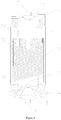
- Fig. 1 shows a large loop for synthesis of methanol, consisting of a single vertical synthesis tower with a water cooling winding tube, and devices for heat exchange, separation and circulation, etc.
- the reactor 1 is a vertical reactor with a water cooling winding tube, the structure of which is shown in Fig. 3 .
- the inlet line of the reactor 1 is connected to the shell side of the heat exchanger 2; the heat exchanger 2 is connected in the front to a circulator 7; the outlet line of the reactor 1 is connected to the tube side of the heat exchanger 2; the tube side outlet of the heat exchanger 2 is connected to an air cooler 3, a water cooler 4 and an alcohol separator 5; the outlet line of the alcohol separator 5 is divided into two lines, one connected to the circulator 7, and the other connected to a hydrogen reclaimer 6.
- the hydrogen reclaimer 6 is also connected to the circulator through a line.
- the reactor 1 is externally connected to a steam drum 8 and a water pump 9.
- a raw gas L1 and a circulating gas L4 are heated to above 210 °C by an output gas L2 from the tower in the heat exchanger 2, and then enter the reactor 1 for synthesis of methanol.
- the reaction heat from the synthesis of methanol heats up water in the winding tube to produce medium-pressure steam.
- the output gas L2 from the tower is cooled to about 40 °C after passing through the heat exchanger 2, the air cooler 3 and the water cooler 4, and then enters the alcohol separator 5 for isolation of methanol.
- a part of the reaction gas with methanol isolated is returned as a circulating gas L4 through the circulator 7; another part is delivered as a released gas L3 to the hydrogen reclaimer 6 for reclaiming hydrogen which is fed back for synthesis of methanol; and the rest part L5 is output as a fuel gas, etc.
- the reactor 1 used in Fig. 1 has a structure as shown in Fig. 3 , comprising a housing, an internal heat-exchange member, an inlet tube case 14 and an outlet tube case 15, wherein the number of each of the inlet tube case 14 and the outlet tube case 15 is 2, and they are provided on a lower seal head 17 and an upper seal head 16 respectively.
- the internal heat-exchange member comprises a heat-exchange winding tube 12 which winds spirally around a mandrel 13 for the winding tube, and two ends of the heat-exchange winding tube are connected to the inlet tube case 14 and the outlet tube case 15 respectively, so as to form two heat-exchange tube bundles having different circular diameters with the tube winding mandrel as a circle center.
- the housing comprises the upper seal head 16, a cylinder body 11 and the lower seal head 17.
- a gas inlet 18 and a gas outlet 19 are provided on the upper seal head 16 and the lower seal head 17 respectively.
- the heat-exchange winding tube 12 is separated and positioned by a positioning strip 20 from inside to outside to form layer-by-layer tube sets, wherein a catalyst is loaded between the heat-exchange winding tubes to form a catalyst layer.
- Man holes are also provided on the upper seal head 16 and the lower seal head 17 for handling catalyst and maintenance. After heated by the heater 2, the mixture of the raw gas L1 and the circulating gas L2 shown in Fig. 1 enters the reactor 1 from the gas inlet 18 shown in Fig. 3 , and particularly enters the catalyst layer to undergo reaction for synthesis of methanol.
- reaction heat is absorbed by the water in the heat-exchange winding tube 12 to produce medium-pressure steam.
- the gas exits the tower from the gas outlet 19.
- the inlet tube case 14 and the outlet tube case 15 of the reactor 1 are connected to the water pump 9 and the steam drum 8 respectively to form a loop.
- the large-scale loop for synthesis of methanol shown in Fig. 2 comprises a water cooling reactor 1a having a water cooling tube wound structure and a gas cooling reactor 1b having a gas cooling tube wound structure.
- the structure of the water cooling reactor 1a is the same as the reactor 1 described in Example 1.
- the gas cooling reactor 1b can be a reactor having the structure of the invention (e.g. reactor 1), or a gas cooling reactor having another type of structure, for example, as described in Chinese patent for invention ZL01808570.9 granted to the applicant of the present application.
- the inlet tube case and the outlet tube case of the water cooling reactor 1a are connected to a water pump 9 and a steam drum 8 to form a loop.
- the shell-side gas inlet of the water cooling reactor 1a is connected to the tube-side outlet of the gas cooling reactor 1b.
- the shell-side gas outlet of the water cooling reactor 1a is connected to the shell-side inlet of the gas cooling reactor 1b.
- the shell-side outlet of the gas cooling reactor 1b is connected to a heat exchanger 2, a water cooler 4 and an alcohol separator 5 sequentially.
- the outlet line of the alcohol separator 5 is divided into two lines, one connected to a circulator 7, and the other connected to a hydrogen reclaimer 6.
- the hydrogen recycler 6 is also connected to the circulator through a line.
- the tube-side inlet of the gas cooling reactor 1b is connected to the circulator 7.
- the water cooling reactor 1a and the gas cooling reactor 1b both use a tube wound structure. They are different in that the heat exchange medium in the heat-exchange winding tube of the water cooling reactor 1a is water, and the heat-exchange winding tube is connected to a steam drum and a water pump via the inlet tube case and the outlet tube case respectively to produce steam, while the heat exchange medium in the heat-exchange winding tube of the gas cooling reactor 1b is the raw gas, and the tube-side inlet and the tube-side outlet of the gas cooling reactor 1b are the inlet and outlet for the heat exchange medium.
- the shell-side inlet and the shell-side outlet are the inlet and outlet for the reaction gas.
- the raw gas L1 and the circulating gas L4 first enter the gas cooling reactor 1b from the tube-side inlet and are heated by an output gas L2 from the tower in the heat-exchange winding tube of the gas cooling reactor 1b. Then, the mixture exits the gas cooling reactor 1b from the tube-side outlet, enters the water cooling reactor 1a from the shell-side, and undergoes reaction for synthesis of methanol in the catalyst layer in the water cooling reactor 1a.
- the reaction heat from the synthesis of methanol heats up water in the heat-exchange winding tube to produce medium-pressure steam.
- the output gas L2 from the tower enters the gas cooling reactor 1b from the shell-side inlet, reacts in the catalyst layer outside the tube in the gas cooling reactor 1b for further synthesis of methanol, heats the raw gas in the heat-exchange winding tube, exists the tower from the shell-side outlet, passes through the heat exchanger 2, the water cooler 4 to be cooled to about 40 °C, and then enters the alcohol separator 5 for isolation of methanol.
- a part of the reaction gas with methanol isolated is returned as a circulating gas L4 through the circulator 7; another part is delivered as a released gas L3 to the hydrogen reclaimer 6 for reclaiming hydrogen which is fed back for synthesis of methanol.
- the rest gas is output as a fuel gas L5.
- the large reactor shown in Fig. 4 is mostly the same as that shown in Fig. 3 in terms of structure, except that an intermediate sleeve 29 is provided to separate the heat-exchange winding tube sets to form an inner catalyst layer and an outer catalyst layer.
- a plurality of supporting rods 30 are provided at one end of the intermediate sleeve 29 to connect the seal head.
- the intermediate sleeve has a diameter which is half of the diameter of the housing.
- the axial water cooling tube wound reactor shown in Fig. 5 comprises a housing, an internal heat-exchange member and an inlet tube case 14, wherein there are two inlet tube cases 14 positioned symmetrically on the lower seal head 17.
- An upper seal head 16, a cylinder body 11 and the lower seal head 17 are provided on the housing.
- Atop steam drum 21, which is also used as an outlet tube case, is provided on the top of the upper seal head 16.
- Two winding tube sets spaced by about 500mm in a sectorial tube distribution zone are connected to a tube sheet 23 between the top steam drum 21 and the upper seal head 16.
- a gas inlet 18 and an upper-seal-head man hole 22b are provided at the side of the upper seal head 16.
- a steam outlet 24 and a steam-drum man hole 22a are provided on the top steam drum 21.
- the steam-drum man hole 22a is used for maintenance, and the upper-seal-head man hole 22b is used for loading catalyst and maintenance.
- a gas outlet 19 and a lower-seal-head man hole (not shown) for unloading catalyst and maintenance are provided on the lower seal head 17.
- the internal heat-exchange member comprises a heat-exchange winding tube 12 which winds spirally around a mandrel 13 for the winding tube, and two ends of the heat-exchange winding tube are connected to the inlet tube case 14 and a sectorial tube set in the tube sheet 23 respectively, so as to form heat-exchange tube bundles having different circular diameters with the tube winding mandrel as a circle center.
- the heat-exchange winding tube 12 is separated and positioned by a positioning strip 20 from inside to outside to form layer-by-layer tube sets, wherein a catalyst is loaded between the heat-exchange winding tubes to form a catalyst layer.
- the raw gas L1 and the circulating gas L2 enter the reactor 1 from the gas inlet 18 shown in Fig. 5 , and particularly enter the catalyst layer to undergo reaction for synthesis of methanol.
- the gas exits the tower from the gas outlet 19.
- the heat-exchange medium, water enters the heat-exchange winding tube 12 from the inlet tube case 14, and moves upward spirally along the heat-exchange winding tube 12.
- the reaction heat from the synthesis of methanol is absorbed by the water in the heat-exchange winding tube 12 to produce medium-pressure steam which enters the top steam drum 21 and exits the reactor from the steam outlet 24.
- the axial-radial tube wound reactor with radial winding followed by axial winding as shown in Fig. 6 comprises a housing, an internal heat-exchange member, an inlet tube case 14 and an outlet tube case 15, wherein the number of each of the inlet tube case 14 and the outlet tube case 15 is 2, and they are provided on a lower seal head 17 and an upper seal head 16 respectively.
- the internal heat-exchange member comprises a heat-exchange winding tube which winds spirally, and two ends of the heat-exchange winding tube are connected to the inlet tube case 14 and the outlet tube case 15 respectively, so as to form heat-exchange tube bundles having different circular diameters with a tube winding mandrel as a circle center.
- the housing comprises the upper seal head 16, a cylinder body 11 and the lower seal head 17.
- a gas outlet 19 are provided on the upper seal head 16 (on the upper seal head, there is also provided an upper-seal-head man hole for loading catalyst and maintenance, not shown in the figure due to the limited room).
- the heat-exchange winding tube 12 is separated and positioned by a positioning strip from inside to outside to form layer-by-layer tube sets (the heat-exchange winding tube in the cylinder body is not shown in Fig. 6 for the purpose of showing clearly the flowing directions of the gas in this example), wherein a catalyst is loaded between the heat-exchange winding tubes to form a catalyst layer.
- a lower-seal-head man hole 22c is provided on the lower seal head 17 for unloading catalyst and maintenance.
- a porous gas collecting cylinder 25 is provided at a middle-to-lower part of an inner wall of the cylinder body 11, and a central gas distributing cylinder 26 is provided at a center of the cylinder body, wherein the central gas distributing cylinder 26 is a hollow structure.
- the central gas distributing cylinder 26 is a hollow mandrel with its bottom sealed, and its top is a gas inlet 18.
- the central gas distributing cylinder 26 has pores at a middle-to-lower part, wherein a stainless steel screen (not shown) is laid on the central gas distributing cylinder 26 and the porous gas collecting cylinder 25 at a side adjacent to the catalyst, wherein the catalyst layer external to the heat-exchange winding tube is between the central gas distributing cylinder 26 and the porous gas collecting cylinder 25.
- a stainless steel screen (not shown) is laid on the central gas distributing cylinder 26 and the porous gas collecting cylinder 25 at a side adjacent to the catalyst, wherein the catalyst layer external to the heat-exchange winding tube is between the central gas distributing cylinder 26 and the porous gas collecting cylinder 25.
- a gas enters from the gas inlet 18 at a top of the central gas distributing cylinder 26 and is distributed uniformly through the distributing pores at the middle-to-lower part of the central gas distributing cylinder 26 into the catalyst layer for reaction, wherein most of the gas passes radially through the catalyst layer, enters the porous gas collecting cylinder 25, and flows upward in the porous gas collecting cylinder 25, wherein the reaction gas exiting the porous gas collecting cylinder 25 and a small portion of the gas exiting the central gas distributing cylinder 26 continue flowing upward axially to leave the reactor from the gas outlet 19.
- the axial-radial tube wound reactor with axial winding followed by radial winding shown in Fig. 7 comprises a housing, an internal heat-exchange member, an inlet tube case 14 and an outlet tube case 15, wherein the housing comprises an upper seal head 16, a cylinder body 11 and a lower seal head 17, wherein the outlet tube case 15, a gas inlet 18 and an upper-seal-head man hole (not shown) for loading catalyst and maintenance are provided on the upper seal head 16, wherein the inlet tube case 14 and a lower-seal-head man hole 22c for unloading catalyst and maintenance are provided on the lower seal head 17.
- the number of the inlet tube case 14 is two, and the number of the outlet tube case 15 is 4, provided on the lower seal head 17 and the upper seal head 16 respectively (in order to show the gas inlet 18 and the lower-seal-head man hole 22c, Fig. 6 only shows one inlet tube case 14 and one outlet tube case 15; they each are actually present in one pair and two pairs respectively).
- the internal heat-exchange member comprises a heat-exchange winding tube which winds spirally, and two ends of the heat-exchange winding tube are connected to the inlet tube case 14 and the outlet tube case 15 respectively, so as to form heat-exchange tube bundles having different circular diameters with the tube winding mandrel as a circle center (the heat-exchange winding tube in the cylinder body is not shown in Fig. 6 for the purpose of showing clearly the flowing directions of the gas in this example).
- a catalyst is loaded between the heat-exchange winding tubes to form a catalyst layer.
- a porous gas distributing cylinder 27 is provided in an inner wall of the cylinder body 11, wherein except for 5% of the length of the porous gas distributing cylinder starting from the top end, pores are made along the rest 95% of the length at the middle-to-lower part, wherein a central gas collecting cylinder 28 is provided at a center of the cylinder body, wherein the central gas collecting cylinder 28 has pores at a middle-to-lower part which accounts for 90% of the length of the central gas collecting cylinder 28 starting from the lower end, wherein a stainless steel screen (not shown) is laid on the central gas collecting cylinder 28 and the porous gas distributing cylinder 27 at a side adjacent to the catalyst layer, wherein the central gas collecting cylinder 28 is fixed at a center of the cylinder body with a positioning ring, wherein the catalyst layer external to the heat-exchange winding tube is between the central gas collecting cylinder 28 and the porous gas distributing cylinder 27, wherein the gas inlet 18 is positioned on the upper seal head, wherein the gas outlet 19
- the reactor in this configuration is an axial-radial tube wound reactor with tubes wound axially first and then radially, wherein a gas enters from the gas inlet 18 on the upper seal head 16, wherein most of the gas flows downward along a gas distributing passage 34 between the housing and the porous gas distributing cylinder 27, and is distributed uniformly through the distributing pores in the porous gas distributing cylinder 27 into the catalyst layer, flows radially through the catalyst layer for reaction, and enters the central gas collecting cylinder 28 from collecting pores in the central gas collecting cylinder 28, wherein a small portion of the gas close to the center flows directly downward axially along an annular space extending along 10% of a height of a bed layer from a top thereof between the porous gas distributing cylinder 27 and the central gas collecting cylinder 28, and flows inward radially to converge in the inner gas collecting cylinder, and then flows upward in the central gas collecting cylinder 28 to exit the reactor from the gas outlet 19 at the top.
- the axial reactor shown in Fig. 3 was used for producing megamethanol at 5000 tons/day, wherein the synthesis pressure was 8.2MPa, the diameter of the reactor was 5.8 meters, and the height of the catalyst bed layer was 7.5 meters.
- a catalyst for synthesis of methanol available from Nanjing Shide Co. was used, wherein the loading of the catalyst was 172M 3 .
- the temperature of the mixed gas was raised to 210 °C or higher by heat exchange with the gas exiting the synthesis tower, and the mixed gas entered the methanol tower for synthesis of methanol at about 250 °C.
- the flow rate of the gas exiting the tower was 78.5 ⁇ 10 4 NM 3 /h.
- the gas exiting the tower contained 19.1% methanol.
- the pressure drop of the reactor was 0.13MPa.
- the total CO conversion was 97.4%, and the total CO 2 conversion was 95.8%.
- Heat was recovered from the gas exiting the tower by heat exchange.
- the gas exiting the tower had a temperature of about 230 °C, was cooled to 40 °C with water, and entered the methanol separator to separate the liquid phase containing about 98% methanol and 2% water.
- the crude methanol product was sent to be rectified to provide fine methanol at 5024 tons/day.
- Most of the gaseous phase was used as a circulating gas which was pressurized and mixed with the raw gas for further synthesis of methanol, and the other part in the form of a released gas was used to reclaim hydrogen by membrane separation, wherein the hydrogen was fed back for synthesis of methanol, and the rest part was utilized as a fuel gas.
- the raw gas was consumed at 2265NM 3 /ton alcohol.
- the reaction heat from the synthesis of methanol heated the boiler water in the winding tube of the reactor to produce 2-4 MPa medium-pressure steam at 1.3 ton steam/ton alcohol.
- the flow rate of the gas entering the tower was 240 ⁇ 10 4 NM 3 /h.
- the temperature of the mixed gas was raised to 220 °C by heat exchange with the gas exiting the synthesis tower, and the mixed gas entered the reactor of the invention for synthesis of methanol at about 250 °C.
- the flow rate of the gas exiting the tower from the bottom was 179.5 ⁇ 10 4 NM 3 /h.
- the gas exiting the tower contained 17.2% methanol.
- the total CO conversion was 99.3%, and the total CO 2 conversion was 94%.
- the temperature was about 230 °C.
- the gas exiting the tower was cooled to 40 °C with water, and entered the methanol separator to separate the liquid phase.
- the crude methanol product containing about 96.3% methanol was sent to be rectified to provide fine methanol at 10369 tons/day.
- Most of the gaseous phase was used as a circulating gas which was mixed with the raw gas for further synthesis of methanol, and a small part in the form of a released gas was used to reclaim hydrogen by membrane separation, wherein the hydrogen was fed back for synthesis of methanol, and the rest part was utilized as a fuel gas.
- the raw gas was consumed at 2265NM 3 /ton alcohol.
- the reaction heat from the synthesis of methanol heated the boiler water in the winding tube of the reactor to produce 2-4 MPa medium-pressure steam at 1.5 ton steam/ton alcohol.
- the pressure drop of the reactor was ⁇ 0.1MPa.
- a large methanol reaction device consisted of two 5000 tons/day large methanol synthesis units in series, wherein each large methanol synthesis unit comprised a large water-cooling reactor, a heat exchanger, an air or water cooler, a methanol separator and a circulator, wherein 97 ⁇ 10 3 NM 3 /h fresh raw gas was all fed to the first methanol synthesis unit for synthesis of methanol at a circulating ratio of 0.134, wherein, except for a portion of an export gas from the methanol separator that was recycled through the circulator to the large reactor for further synthesis of methanol, the rest released gas was discharged into the second methanol synthesis unit at the back in series at a circulating ratio of 2 for synthesis of methanol, wherein a released gas from the second methanol synthesis unit was delivered to an effective gas (hydrogen) reclaiming device to reclaim hydrogen, wherein the reclaimed hydrogen was merged with the fresh raw gas, and then pressurized and delivered to the
Landscapes
- Chemical & Material Sciences (AREA)
- Organic Chemistry (AREA)
- Chemical Kinetics & Catalysis (AREA)
- Physics & Mathematics (AREA)
- Fluid Mechanics (AREA)
- Devices And Processes Conducted In The Presence Of Fluids And Solid Particles (AREA)
- Organic Low-Molecular-Weight Compounds And Preparation Thereof (AREA)
Description
- The disclosure is directed to the field of oil and coal chemical industry, particularly to fluid fixed-bed catalytic reactions and heat transfer processes, even particularly to strong exothermic and endothermic chemical reactions of methanol, ethylene oxide, ethylene glycol, methanation, dimethyl ether, hydrocarbons and the like in petrochemical industry and coal chemical industry.
- The coal chemical industry in China has attracted attention around the world nowadays for the following reasons. First, the development is rapid, and the investments are tremendous. Second, the scale is large. National Development and Reform Commission places requirements on the scale of new coal chemical projects. For example, the yield for synthesis of methanol should be 1 million tons per year; and the yield for synthesis of ethylene glycol should be 0.2 million tons per year. Some well-known foreign companies such as Lurgi, DAVY, among others, each have succeeded in development of processes for synthesis of megamethanol at 5000 tons per day, and these processes have been put into operation in the coal chemical devices of Shenhua Ningxia Coal Industry Group Corporation and Baotou, etc in China. Third, foreign technologies are utilized in all the large reactors in the coal chemical projects. Fourth, a combination of several reactors is employed in the large-scale coal chemical projects due to the low capability of a single reactor.
- Up to date, multinational companies have developed a number of types of reactors successfully. For the most commonly used fixed-bed reactor, there are adiabatic type, quenching type, water or air cooling heat exchange type, tubular or plate heat exchange type, axial or radial type, vertical or horizontal type reactors. The DAVY radial converter has low resistance, but its capability of heat transfer is insufficient. As a result, a hot spot in operation has a temperature up to more than 300°C, affecting the service life of a catalyst. Both the Lurgi water cooling and air cooling converters in tandem for megamethanol are radial converters, wherein the pressure drop in the synthesis converter and the resistance in the synthesis loop are large. The total resistance is up to more than 0.7MPa, and thus the power consumption is increased.
-
WO2007021393 andCN101243027 to Exxon-mobil Chemical Corporation, USA disclose a large reaction system for synthesis of methanol, consisting of a tube-shell reactor, a gas cooling tube and a catalytic reactor external to a water cooling tube in series. The diameter is 5.8 m, and the total height of the bed is 22 m, and the single path conversion of CO is 35.3%. This system also has the problem that the larger the reactor is, the larger the resistance is in synthesis. - During upsizing of both domestic and foreign petrochemical engineering projects, a conflict between a high heat transfer efficiency and a high catalyst loading coefficient occurs in the design of an industrial catalytic reactor. For example, a tube-shell reactor has good capability of heat transfer, and has been used widely as a large reactor for synthesis of methanol and ethylene oxide in tens of years. However, as the expensive catalyst is loaded in a reaction tube of 2-5 cm, the catalyst space effectively used for the reaction is generally not higher than a third of the whole reactor. For example, in Yangzi Petrochemical Company Ltd, China, a tube-shell reactor for synthesis of ethylene oxide at a yield of 0.18 million tons per year has a diameter up to 7 meters, a length of 22 meters, more than 15000 reaction tubes, and a weight up to 850 tons. From design, manufacture, processing to shipment and installation, several units made great joint efforts to address the challenges, so that the project was finished smoothly. In addition, except for adiabatic type and quenching type reactors, the internal members of all water or gas cooling heat exchange type reactors include a large number of heat exchangers of the type of heat exchange tube that are welded to a main for inlet and outlet of water or gas, or a good number of catalyst loaded reaction tubes welded to a large tube sheet. When the reactors are put into operation, the welding spots likely crack due to variation of the operating conditions such as temperature, stress, etc, leading to leak which will affect the production.
- All in all, no matter at home or abroad, there is so far no large methanol synthesis converter having good process performances, a uniform temperature, a high conversion, a high space utility, a high energy efficiency, and a yield of 1 million tons per year per unit.
-
CN 202 460 592 U (hereinafter CN '592) andCN 103 240 036 (hereinafter CN '036) were applications for utility model and for invention, filed by the same Applicant on the same filing date. As described inLine 4 ofclaim 1 of CN '592 and CN '036, the bottoms of two adjacent inner and outer ring heat exchange tubes or two adjacent heat exchange tubes of the same ring diameter are connected by a U-shaped bend to form an upward heat exchange tube and a downward heat exchange tube arrangement for internal heat exchange medium. The upward heat exchange tube is connected to the outlet tube case, and the downward heat exchange tube is connected to the inlet tube case; or the tops of two adjacent inner and outer ring heat exchange tubes or two adjacent heat exchange tubes of the same ring diameter are connected by an inverted U-shaped bend, and the upward heat exchange tube connecting the inverted U-shaped bend is connected to the inlet tube case, and the downward heat exchange tube is connected to the outlet tube case". The structures of the U-shaped bend and the inverted U-shaped bend are described in detail inFigures 8-9 of CN '592 and CN '036. The water-cooled winding tube case is set on the upper or lower part of the shell. As shown inFigure 1 of CN '592 and CN '036, the inlet tube case is set on the upper part. The water within the tube flows through the tube 2b and flows downward with the reaction gas outside the tube, and then changes its direction via the U-shaped bend 18a, and then flows upward through the tube 2a, in a direction contrary to the reaction gas stream outside the tube (seeFig. 8 of CN '592 and CN '036). Or, as shown inFigure 2 of CN '592 and CN '036, the inlet tube case is located at the lower part, and connected to the lower inlet tube 2a. Water flows upward, in contrary direction with the reaction gas outside the tube, to the tube end, and then flows downwards via the inverted U-shaped bend 18b to the tube 2b (see Figure 9 of CN '592 and CN '036). -
CN 203 096 014 U (hereinafter CN '014) relates to a device for producing natural gas using water gas. As shown in the description of Example 3 of CN '014 andFigure 5 of CN '014, it uses the same structure as CN '592 and CN '036. - In CN '592, CN '014 and CN '036, the inlet and outlet tube cases of the water-cooled winding tube heat exchanger reactor are all set at the upper end of the shell, or the inlet and outlet tube cases are all at the lower end of the shell. The water in the inlet tube changes its direction via the U-shaped or inverted U-shaped bend located in the middle of the tube.
- In view of the drawbacks of the reaction technologies and reactors for large-scale processes in the prior art, the disclosure proposes a solution for the reaction technologies and reactors for large-scale processes, featuring a uniform temperature, a high efficiency and a low pressure drop.
- To achieve the above object, the present invention provides a large reactor according to the appended
independent claim 1, and a large-scale process according to the appendedindependent claim 7. Preferable embodiments of the invention are provided by the appended dependent claims 2-6 and 8-9. - The disclosure utilizes the following technical solution:
A large reactor, comprising a housing, an internal heat-exchange member, an inlet tube case and an outlet tube case, wherein the internal heat-exchange member comprises a heat-exchange winding tube; wherein the housing comprises an upper seal head, a cylinder body, a lower seal head; wherein a gas inlet and a gas outlet are provided on the upper seal head and the lower seal head respectively; wherein the numbers of the inlet tube case and/or the outlet tube case each are 2 or a multiple of 2, which are respectively provided on the lower seal head and the upper seal head, or on a lower part and an upper part of the cylinder body, arranged uniformly in a circumferentially symmetric manner, which facilitates uniform distribution and flow of a reaction gas in a catalyst layer in a heat-exchange tube in the reactor, improves reaction efficiency, and effects easy discharge of the catalyst from a bottom; wherein a small diameter tube case tube sheet is used to replace a large tube case tube sheet to reduce a thickness of the tube sheet, so as to save a device material and cost. The inlet tube case and the outlet tube case are connected to two ends of the heat-exchange winding tube respectively, wherein the heat-exchange winding tube is separated and positioned by a positioning strip and winds into a layer-by-layer tube set, wherein a catalyst is loaded between heat-exchange winding tubes to form a catalyst layer. - A steam drum is provided on the upper seal head, also used as an outlet tube case, wherein an even number of winding tube sets in a sectorial tube distribution zone are connected to a tube sheet between the steam drum and the upper seal head.
- Preferably, the large reactor is a radial-axial reactor, wherein a porous gas collecting cylinder is provided at a middle-to-lower part of an inner wall of the cylinder body, and a central gas distributing cylinder is provided at a center of the cylinder body, wherein the central gas distributing cylinder has pores at a middle-to-lower part, wherein a stainless steel screen is laid on the central gas distributing cylinder and the porous gas collecting cylinder at a side adjacent to the catalyst, wherein the catalyst layer external to the heat-exchange winding tube is between the central gas distributing cylinder and the porous gas collecting cylinder, wherein the gas outlet is positioned on the upper seal head, wherein the gas inlet is positioned at a top of the central gas distributing cylinder, wherein the central gas distributing cylinder is a hollow mandrel with its bottom sealed. The reactor in this configuration is a reactor with tubes wound radially first and then axially, wherein a gas enters from the gas inlet at a top of the central gas distributing cylinder and is distributed uniformly through the distributing pores at the middle-to-lower part of the central gas distributing cylinder into the catalyst layer, wherein most of the gas passes radially through the catalyst layer, enters the porous gas collecting cylinder, and flows upward axially in the porous gas collecting cylinder, wherein the reaction gas exiting the porous gas collecting cylinder continues flowing upward axially to leave the reactor from the gas outlet.
- Preferably, the large reactor is an axial-radial reactor, wherein a porous gas distributing cylinder is provided at a middle-to-lower part of an inner wall of the cylinder body, wherein the middle-to-lower part accounts for 90-95% of a length of the inner wall starting from a lower end, wherein a central gas collecting cylinder is provided at a center of the cylinder body, wherein the central gas collecting cylinder has pores at a middle-to-lower part which accounts for 90-95% of a length of the central gas collecting cylinder starting from a lower end, wherein a stainless steel screen is laid on the central gas collecting cylinder and the porous gas distributing cylinder at a side adjacent to the catalyst layer, wherein the central gas collecting cylinder is fixed at a center of the cylinder body with a positioning ring, wherein the catalyst layer external to the heat-exchange winding tube is between the central gas collecting cylinder and the porous gas distributing cylinder, wherein the gas inlet is positioned on the upper seal head, wherein the gas outlet is positioned at a top of the central gas collecting cylinder. The reactor in this configuration is a reactor with tubes wound axially first and then radially, wherein a gas enters from the gas inlet on the upper seal head, wherein most of the gas flows downward along a gas distributing passage between the housing and the porous gas distributing cylinder, and is distributed uniformly through the distributing pores in the porous gas distributing cylinder into the catalyst layer, flows radially through the catalyst layer, and enters the central gas collecting cylinder from collecting pores in the central gas collecting cylinder, wherein a small portion of the gas flows directly downward axially in an annular space extending along 10% of a height of a bed layer from a top thereof between the porous
gas distributing cylinder 27 and the centralgas collecting cylinder 28, and flows inward radially to converge in the inner gas collecting cylinder, and then flows upward in the central gas collecting cylinder to exit the reactor from the gas outlet at the top. - Preferably, the heat-exchange winding tube is a small-size spiral heat-exchange tube having an inner diameter of 10-25 mm.
- Preferably, a spacing of two axially adjacent tube walls of a portion of the heat-exchange winding tube extending along 10-50% of a height of the catalyst bed layer from a top thereof is 10-90% of a normal uniform spacing.
- The reaction rate of a gas in the catalyst bed layer and the released reaction heat vary, i.e. the reaction rate is higher in the front part of the reactor than at the back part of the reactor, and the released reaction heat is more in the front part of the reactor than at the back part of the reactor. When a tube-shell reactor is used, the heat-exchange area is the same, and thus a peak reaction temperature occurs in the front part of the bed layer. For this reason, the spacing of two vertically adjacent tube walls of the heat-exchange tube is reduced in the front part of the catalytic reactor according to the disclosure. For example, the tube wall spacing of a 10-50% portion of the bed layer starting from the gas inlet is reduced by 10-90% to enlarge the heat-exchange area and increase the heat removal rate. As such, the problems of overheating of hot spots in the catalyst layer and deactivation caused by unduly high temperatures are solved, and the service life of the catalyst is extended.
- Preferably, a spacing of two axially adjacent tube walls of a portion of the heat-exchange winding tube extending along 20% of a height of the catalyst bed layer from a bottom thereof is 10-90% of a normal uniform spacing. At the bottom of the catalytic reaction bed layer, the product content in the reaction gas is high, and the temperature of the reaction gas is close to the equilibrium temperature of the product for an exothermic reaction. In order to further increase the product content, the tube wall spacing can also be reduced. For example, the tube wall spacing of a portion of the heat-exchange tube located deeper than 80% of the bed layer can be reduced by 10-90%, so as to remove more heat and reduce the reaction temperature, which is helpful for further increasing the product content.
- Preferably, the heat-exchange winding tube set is separated by an intermediate sleeve or a perforated sleeve to provide an inner catalyst layer and an outer catalyst layer, wherein an end of the intermediate sleeve or perforated sleeve is connected to the seal head via a plurality of supporting rods, wherein the intermediate sleeve or perforated sleeve has a diameter of 1/2 to 1/3 of the diameter of the housing.
- Preferably, the large reaction device comprises a single large axial water cooling tube wound reactor, or two or three large axial water cooling tube wound reactors in parallel connected to a large gas-cooling reactor in series.
- The large reactor described above can be used in exothermic or endothermic reactions such as conversion of carbon monoxide from synthetic gas to carbon dioxide and hydrogen, oxidation of hydrogen sulfide to prepare sulfur, synthesis of oil by Fischer-Tropsch reaction, methanation, production of ethylene oxide and ethylene glycol, synthesis of ammonia, synthesis of methylamine from methanol and ammonia, etc.
- The large multi-stage methanol reaction device consists of two large methanol synthesis units in series, wherein each large methanol synthesis unit comprises a large water-cooling reactor, a heat exchanger, an air or water cooler, a methanol separator and a circulator, wherein a fresh raw gas is all fed to a first methanol synthesis unit, wherein, except for a portion of an export gas from the methanol separator that is recycled through the circulator at a circulating ratio <0.5 to the large reactor for further synthesis of methanol, the rest released gas is discharged into the second methanol synthesis unit at the back in series at a circulating ratio of 1.5-4 for synthesis of methanol, wherein a released gas from the second stage synthesis unit is delivered to an effective gas (hydrogen) recycling device to recycle hydrogen, wherein the reclaimed hydrogen is merged with the fresh raw gas, and then pressurized and delivered to the first synthesis unit for synthesis of methanol.
- A large-scale process for synthesis of methanol using the above large reactor at a low circulating ratio of <3 and a high net value of >10%, including the following steps:
- 1) mixing a fresh raw gas with hydrogen reclaimed from a released gas from the synthesis to form a mixed gas, wherein

- 2) raising a temperature of the mixed gas to above 210°C by heat exchange in a heat exchanger, wherein reaction heat from the synthesis of methanol heats up water in a heat-exchange winding tube to produce a medium-pressure steam, wherein methanol in a reaction gas arriving at an outlet has a molar percentage of >10%;
- 3) cooling a hot gas having a high content of methanol exiting the large reactor by heat exchange in a heat exchanger, wherein cooling is achieved by heating water in a boiler or with an air cooler, wherein the gas is then cooled to about 40 °C by water cooling, and then delivered to an alcohol separator for isolation of methanol;
- 4) recycling the reaction gas after product separation through a circulator to undergo further reaction, wherein the ratio of the circulating gas to the fresh raw gas, namely the circulating ratio, is less than 3, wherein, as another part, the released gas is subjected to membrane separation, pressure swing absorption or the like to recycle effective hydrogen which returns to synthesize methanol, or enters a next methanol synthesis reaction loop for further reaction to form methanol, or the released gas is used for co-production of other products or for power generation.
- A large-scale process for synthesis of ethylene oxide by ethylene oxidation using the above large reactor, including the following steps:
- 1) adding a CH4 stabilizer and pure oxygen, or adding air to an ethylene raw material purified to remove explosive alkane components including H2, alkenes of C3 or above to obtain a mixed raw gas comprising mainly ethylene 20-30%, oxygen 7-10%, methane 45-63%, or introducing nitrogen by oxidation with air;
- 2) mixing the raw gas and a circulating gas, wherein the resulting mixture is heated to about 180 °C with an in-and-out-of-tower heat exchanger at a pressure level of 2 MPa, and then enters a large reactor for synthesis of ethylene oxide;
- 3) allowing the gas entering the tower to undergo reaction of ethylene oxidation to produce ethylene oxide on a gaseous phase silver catalyst comprising 10-20wt% silver and the balance of a co-catalyst and a support between a heat-exchange tube and a housing of the reactor, wherein oxidation reaction heat is absorbed by water in the tube to produce a medium-pressure steam, wherein a temperature of the oxidation reaction is controlled by controlling a pressure of the steam byproduct;
- 4) lowering a temperature of a reaction gas exiting the reactor by cooling it as the reaction gas heats a gas entering the reactor with heat transferred in a hot gas passage in a heat exchanger;
- 5) allowing the reaction gas exiting the heat exchanger to enter an absorption tower to absorb ethylene oxide as a product, wherein a C2H4O rich liquid at a bottom of the absorption tower is delivered to a post treatment station, wherein a small amount of released gas is discharged intermittently from a gas at a top of the absorption tower to avoid inert gas accumulation, and a small part of the gas passes through a CO2 removing tower and is pressurized in a circulator together with the rest of the gas without removal of CO2, wherein the pressurized gas returns to merge with the mixed raw gas in front of the reactor and then enters the reactor for synthesis of ethylene oxide.
- The invention possesses outstanding advantages as compared with the prior art, and a specific comparison is shown in the table below:
Economical comparison between the main technical apparatuses for producing 5000 tons/day megamethanolDeveloper British DAVY German Lurgi British JOHSON MATTHEY American EXXON MOBIL The invention Technical characteristics Water cooling tube, radial tower in series/parallel Two tube-shell in parallel Water cooling-gas cooling in series Two adiabatic towers and one gas cooling tower in series Water cooling tube shell; gas cooling tube tower, water cooling tube tower in series Single water cooling winding tube Example 7 Example 8 Output (ton/day) 5400 5000 2700 6000 5000 10000 Synthesis pressure (MPa) 8.0 8.5 8.4 4.7 8.2 8.2 Synthesis tower diameter * height 5.2∗10 4∗10 one 5.5∗8 tower two 5.8∗7 towers 5.8∗7.5 5.4∗18.8 Number of synthesis towers (unit) 2 3 3 3 1 2 Empty capacity of the synthesis tower (M3) 390 215 560 Total amount of the catalyst (M3) 205 180 116.4 about 335 172 356 Heat exchanges (unit) 2 1 3 1 1 1 Water cooling alcohol separator (unit) 2 1 1 1 1 1 Circulator (unit) 1 1 1 1 1 1 Circulating ratio 5.6 1.5 3 1.3 1.47 Alcohol net value (%) <5 16.3 6.4 19 17.2 Pressure drop in the synthesis loop (MPa) 0.9 0.76 low ≦ 0.6 ≦ 0.6 Synthesis temperature (°C) high >300°C 209-280°C large temperature difference front tower 247-283°C back Tower 170-210°C 220-270° C 220-270° C Catalyst life relatively short long relatively short medium long long Byproduct of methanol relatively high low medium medium low low Raw gas consumption Nm3/ton 2330 2338 3291 2265 2265 Byproduct steam /ton alcohol low, <ton/T low, 0.8 ton/T producing hot water <0.8 ton/T ≧ 1.3 ≧ 1.3 Investment 100 100 85 90 70 60 Energy consumption relatively high medium relatively high medium low low Source Chemical Engineering Design Communication , p. 58, December, 2013 CN101301597A balance sheet of materials for methanol production from Datang Duolun WO200406 5341 CN1012430 27 Amount of catalyst (M3) when normalized to 5000 tons/day 197 180 215 194 172 178 - As can be seen from above, the main advantages include:
- 1. Easy scaling up: as the temperature is homogeneous, the activity of the catalyst can be improved significantly. In addition, the catalyst loading coefficient is doubled as compared with the tube-shell type. Hence, scaling up can be realized easily. For example, one methanol tower can replace several synthesis towers of foreign companies Lurgi, DAVY and the like using megamethanol technologies.
- 2. Energy can be saved, and consumption can be reduced. The synthesis conversion is high, while the consumption of raw materials is low. The amount of the byproduct steam is high, and the recovery of heat is excellent. The circulating ratio is small, the power consumption is low, and the operating cost is also low.
- 3. Low investment: the tubes in the device are small; the footprint area is small. The investment is low, as one unit has the effect of two prior art units. The catalyst loading coefficient in the synthesis tower is high, and the catalyst per unit is highly active. The efficiency and the yield are high. The reaction heat can be used effectively. A large amount of steam is produced from the reactor. The recovery of the heat is high. The circulating ratio is low, and the net value of the product is high. The resistance is small, and the power and energy consumption is low.
- 4. The structure is safe and reliable. As the internal members are free of welding spots, and the elastic structure of the spiral heat-exchange tube has no temperature stress, the safety and reliability of the structure of the synthesis tower is guaranteed fundamentally, and there is no risk of leak. The welding spots of the tubes to the tube sheet are located at the tube case on the housing, and thus inspection and repairing have no influence on the catalyst activity. As such, the challenges of manufacture, assembly, maintenance and shipment of large towers are addressed successfully with high security and reliability.
- 5. Optimized design and easy scaling up: with advanced designing means mastered, a mathematical model has been constructed for a tube wound synthesis tower, which is suitable for various production capacities and process conditions and parameter calculations to optimize structural parameters, so as to achieve the best effects. As there are no large tube sheets or baffle plates, and a structure featuring small heat-exchange tube cases and positioning strips is used, the challenge of processing a large diameter tower is addressed.
-
-
Fig. 1 is a schematic view showing a large loop for synthesis of methanol, consisting of a single vertical synthesis tower with an axial water cooling winding tube, and devices for heat exchange, separation and circulation, etc. -
Fig. 2 shows an assembly of a water cooling tube wound tower and a gas cooling tube wound tower in series. -
Fig. 3 shows an axial water cooling tube wound reactor comprising an even number of paired inlet and outlet tube cases. -
Fig. 4 shows an axial water cooling tube wound reactor with an intermediate sleeve provided. -
Fig. 5 shows an axial water cooling tube wound reactor with a steam drum provided on an upper seal head on the synthesis tower. -
Fig. 6 shows an axial-radial tube wound reactor with radial winding followed by axial winding. -
Fig. 7 shows an axial-radial tube wound reactor with axial winding followed by radial winding. -
Fig. 8 shows a process flow chart of a large-scale process for synthesis of ethylene oxide by oxidation of ethylene. - Notes on the reference numbers:
1- reactor 2-heat exchanger 3- air cooler 4- water cooler 5- alcohol 6- hydrogen reclaimer 7- circulator 8- steam drum separator 9-water pump 1a-water cooling 1b-gas cooling 11- cylinder body reactor reactor 12- heat-exchange 13- winding tube 14- inlet tube case 15- outlet tube case winding tube mandrel 16- upper seal 17-lower seal head 18-gas inlet 19-gas outlet head 20- positioning 21-top steam drum 22a- man hole on 22b- man hole on strip steam drumupper seal head 22b- man hole on 23- tube sheet 24- steam outlet 25- porous gas lower seal head collecting cylinder 26- central gas 27- porous gas 28- central gas 29- intermediate distributing distributing cylinder collecting cylinder sleeve cylinder 30- supporting rod 31- mixer 32- absorption 33- CO2 removal Tower tower L1-raw gas L2- output gas from L3- released gas L4- circulating gas tower L5- fuel gas 34- gas distributing passage - The invention will be illustrated in detail with reference to the drawings and the following examples.
-
Fig. 1 shows a large loop for synthesis of methanol, consisting of a single vertical synthesis tower with a water cooling winding tube, and devices for heat exchange, separation and circulation, etc. Thereactor 1 is a vertical reactor with a water cooling winding tube, the structure of which is shown inFig. 3 . The inlet line of thereactor 1 is connected to the shell side of theheat exchanger 2; theheat exchanger 2 is connected in the front to acirculator 7; the outlet line of thereactor 1 is connected to the tube side of theheat exchanger 2; the tube side outlet of theheat exchanger 2 is connected to anair cooler 3, awater cooler 4 and analcohol separator 5; the outlet line of thealcohol separator 5 is divided into two lines, one connected to thecirculator 7, and the other connected to ahydrogen reclaimer 6. Thehydrogen reclaimer 6 is also connected to the circulator through a line. Thereactor 1 is externally connected to asteam drum 8 and awater pump 9. After mixing, a raw gas L1 and a circulating gas L4 are heated to above 210 °C by an output gas L2 from the tower in theheat exchanger 2, and then enter thereactor 1 for synthesis of methanol. The reaction heat from the synthesis of methanol heats up water in the winding tube to produce medium-pressure steam. The output gas L2 from the tower is cooled to about 40 °C after passing through theheat exchanger 2, theair cooler 3 and thewater cooler 4, and then enters thealcohol separator 5 for isolation of methanol. A part of the reaction gas with methanol isolated is returned as a circulating gas L4 through thecirculator 7; another part is delivered as a released gas L3 to thehydrogen reclaimer 6 for reclaiming hydrogen which is fed back for synthesis of methanol; and the rest part L5 is output as a fuel gas, etc. - The
reactor 1 used inFig. 1 has a structure as shown inFig. 3 , comprising a housing, an internal heat-exchange member, aninlet tube case 14 and anoutlet tube case 15, wherein the number of each of theinlet tube case 14 and theoutlet tube case 15 is 2, and they are provided on alower seal head 17 and anupper seal head 16 respectively. The internal heat-exchange member comprises a heat-exchange winding tube 12 which winds spirally around amandrel 13 for the winding tube, and two ends of the heat-exchange winding tube are connected to theinlet tube case 14 and theoutlet tube case 15 respectively, so as to form two heat-exchange tube bundles having different circular diameters with the tube winding mandrel as a circle center. The housing comprises theupper seal head 16, acylinder body 11 and thelower seal head 17. Agas inlet 18 and agas outlet 19 are provided on theupper seal head 16 and thelower seal head 17 respectively. The heat-exchange winding tube 12 is separated and positioned by apositioning strip 20 from inside to outside to form layer-by-layer tube sets, wherein a catalyst is loaded between the heat-exchange winding tubes to form a catalyst layer. Man holes are also provided on theupper seal head 16 and thelower seal head 17 for handling catalyst and maintenance. After heated by theheater 2, the mixture of the raw gas L1 and the circulating gas L2 shown inFig. 1 enters thereactor 1 from thegas inlet 18 shown inFig. 3 , and particularly enters the catalyst layer to undergo reaction for synthesis of methanol. The reaction heat is absorbed by the water in the heat-exchange winding tube 12 to produce medium-pressure steam. After reaction, the gas exits the tower from thegas outlet 19. Theinlet tube case 14 and theoutlet tube case 15 of thereactor 1 are connected to thewater pump 9 and thesteam drum 8 respectively to form a loop. - The large-scale loop for synthesis of methanol shown in
Fig. 2 comprises awater cooling reactor 1a having a water cooling tube wound structure and agas cooling reactor 1b having a gas cooling tube wound structure. The structure of thewater cooling reactor 1a is the same as thereactor 1 described in Example 1. Thegas cooling reactor 1b can be a reactor having the structure of the invention (e.g. reactor 1), or a gas cooling reactor having another type of structure, for example, as described in Chinese patent for inventionZL01808570.9 - The inlet tube case and the outlet tube case of the
water cooling reactor 1a are connected to awater pump 9 and asteam drum 8 to form a loop. The shell-side gas inlet of thewater cooling reactor 1a is connected to the tube-side outlet of thegas cooling reactor 1b. The shell-side gas outlet of thewater cooling reactor 1a is connected to the shell-side inlet of thegas cooling reactor 1b. The shell-side outlet of thegas cooling reactor 1b is connected to aheat exchanger 2, awater cooler 4 and analcohol separator 5 sequentially. The outlet line of thealcohol separator 5 is divided into two lines, one connected to acirculator 7, and the other connected to ahydrogen reclaimer 6. Thehydrogen recycler 6 is also connected to the circulator through a line. The tube-side inlet of thegas cooling reactor 1b is connected to thecirculator 7. - The
water cooling reactor 1a and thegas cooling reactor 1b both use a tube wound structure. They are different in that the heat exchange medium in the heat-exchange winding tube of thewater cooling reactor 1a is water, and the heat-exchange winding tube is connected to a steam drum and a water pump via the inlet tube case and the outlet tube case respectively to produce steam, while the heat exchange medium in the heat-exchange winding tube of thegas cooling reactor 1b is the raw gas, and the tube-side inlet and the tube-side outlet of thegas cooling reactor 1b are the inlet and outlet for the heat exchange medium. The shell-side inlet and the shell-side outlet are the inlet and outlet for the reaction gas. - After mixing, the raw gas L1 and the circulating gas L4 first enter the
gas cooling reactor 1b from the tube-side inlet and are heated by an output gas L2 from the tower in the heat-exchange winding tube of thegas cooling reactor 1b. Then, the mixture exits thegas cooling reactor 1b from the tube-side outlet, enters thewater cooling reactor 1a from the shell-side, and undergoes reaction for synthesis of methanol in the catalyst layer in thewater cooling reactor 1a. The reaction heat from the synthesis of methanol heats up water in the heat-exchange winding tube to produce medium-pressure steam. The output gas L2 from the tower enters thegas cooling reactor 1b from the shell-side inlet, reacts in the catalyst layer outside the tube in thegas cooling reactor 1b for further synthesis of methanol, heats the raw gas in the heat-exchange winding tube, exists the tower from the shell-side outlet, passes through theheat exchanger 2, thewater cooler 4 to be cooled to about 40 °C, and then enters thealcohol separator 5 for isolation of methanol. A part of the reaction gas with methanol isolated is returned as a circulating gas L4 through thecirculator 7; another part is delivered as a released gas L3 to thehydrogen reclaimer 6 for reclaiming hydrogen which is fed back for synthesis of methanol. - After hydrogen is reclaimed, the rest gas is output as a fuel gas L5.
- The large reactor shown in
Fig. 4 is mostly the same as that shown inFig. 3 in terms of structure, except that anintermediate sleeve 29 is provided to separate the heat-exchange winding tube sets to form an inner catalyst layer and an outer catalyst layer. A plurality of supportingrods 30 are provided at one end of theintermediate sleeve 29 to connect the seal head. The intermediate sleeve has a diameter which is half of the diameter of the housing. - The axial water cooling tube wound reactor shown in
Fig. 5 comprises a housing, an internal heat-exchange member and aninlet tube case 14, wherein there are twoinlet tube cases 14 positioned symmetrically on thelower seal head 17. Anupper seal head 16, acylinder body 11 and thelower seal head 17 are provided on the housing. Atopsteam drum 21, which is also used as an outlet tube case, is provided on the top of theupper seal head 16. Two winding tube sets spaced by about 500mm in a sectorial tube distribution zone are connected to a tube sheet 23 between thetop steam drum 21 and theupper seal head 16. Agas inlet 18 and an upper-seal-head man hole 22b are provided at the side of theupper seal head 16. Asteam outlet 24 and a steam-drum man hole 22a are provided on thetop steam drum 21. The steam-drum man hole 22a is used for maintenance, and the upper-seal-head man hole 22b is used for loading catalyst and maintenance. Agas outlet 19 and a lower-seal-head man hole (not shown) for unloading catalyst and maintenance are provided on thelower seal head 17. The internal heat-exchange member comprises a heat-exchange winding tube 12 which winds spirally around amandrel 13 for the winding tube, and two ends of the heat-exchange winding tube are connected to theinlet tube case 14 and a sectorial tube set in the tube sheet 23 respectively, so as to form heat-exchange tube bundles having different circular diameters with the tube winding mandrel as a circle center. The heat-exchange winding tube 12 is separated and positioned by apositioning strip 20 from inside to outside to form layer-by-layer tube sets, wherein a catalyst is loaded between the heat-exchange winding tubes to form a catalyst layer. - Using the device of
Fig. 1 , after mixing, the raw gas L1 and the circulating gas L2 enter thereactor 1 from thegas inlet 18 shown inFig. 5 , and particularly enter the catalyst layer to undergo reaction for synthesis of methanol. After reaction, the gas exits the tower from thegas outlet 19. The heat-exchange medium, water, enters the heat-exchange winding tube 12 from theinlet tube case 14, and moves upward spirally along the heat-exchange winding tube 12. The reaction heat from the synthesis of methanol is absorbed by the water in the heat-exchange winding tube 12 to produce medium-pressure steam which enters thetop steam drum 21 and exits the reactor from thesteam outlet 24. - The axial-radial tube wound reactor with radial winding followed by axial winding as shown in
Fig. 6 comprises a housing, an internal heat-exchange member, aninlet tube case 14 and anoutlet tube case 15, wherein the number of each of theinlet tube case 14 and theoutlet tube case 15 is 2, and they are provided on alower seal head 17 and anupper seal head 16 respectively. The internal heat-exchange member comprises a heat-exchange winding tube which winds spirally, and two ends of the heat-exchange winding tube are connected to theinlet tube case 14 and theoutlet tube case 15 respectively, so as to form heat-exchange tube bundles having different circular diameters with a tube winding mandrel as a circle center. The housing comprises theupper seal head 16, acylinder body 11 and thelower seal head 17. Agas outlet 19 are provided on the upper seal head 16 (on the upper seal head, there is also provided an upper-seal-head man hole for loading catalyst and maintenance, not shown in the figure due to the limited room). The heat-exchange winding tube 12 is separated and positioned by a positioning strip from inside to outside to form layer-by-layer tube sets (the heat-exchange winding tube in the cylinder body is not shown inFig. 6 for the purpose of showing clearly the flowing directions of the gas in this example), wherein a catalyst is loaded between the heat-exchange winding tubes to form a catalyst layer. A lower-seal-head man hole 22c is provided on thelower seal head 17 for unloading catalyst and maintenance. - A porous
gas collecting cylinder 25 is provided at a middle-to-lower part of an inner wall of thecylinder body 11, and a centralgas distributing cylinder 26 is provided at a center of the cylinder body, wherein the centralgas distributing cylinder 26 is a hollow structure. The centralgas distributing cylinder 26 is a hollow mandrel with its bottom sealed, and its top is agas inlet 18. The centralgas distributing cylinder 26 has pores at a middle-to-lower part, wherein a stainless steel screen (not shown) is laid on the centralgas distributing cylinder 26 and the porousgas collecting cylinder 25 at a side adjacent to the catalyst, wherein the catalyst layer external to the heat-exchange winding tube is between the centralgas distributing cylinder 26 and the porousgas collecting cylinder 25. (In order to show thegas outlet 19 and the lower-seal-head man hole 22c,Fig. 6 only shows oneinlet tube case 14 and oneoutlet tube case 15; they each are actually present in a pair.) - A gas enters from the
gas inlet 18 at a top of the centralgas distributing cylinder 26 and is distributed uniformly through the distributing pores at the middle-to-lower part of the centralgas distributing cylinder 26 into the catalyst layer for reaction, wherein most of the gas passes radially through the catalyst layer, enters the porousgas collecting cylinder 25, and flows upward in the porousgas collecting cylinder 25, wherein the reaction gas exiting the porousgas collecting cylinder 25 and a small portion of the gas exiting the centralgas distributing cylinder 26 continue flowing upward axially to leave the reactor from thegas outlet 19. - The axial-radial tube wound reactor with axial winding followed by radial winding shown in
Fig. 7 comprises
a housing, an internal heat-exchange member, aninlet tube case 14 and anoutlet tube case 15, wherein the housing comprises anupper seal head 16, acylinder body 11 and alower seal head 17, wherein theoutlet tube case 15, agas inlet 18 and an upper-seal-head man hole (not shown) for loading catalyst and maintenance are provided on theupper seal head 16, wherein theinlet tube case 14 and a lower-seal-head man hole 22c for unloading catalyst and maintenance are provided on thelower seal head 17. The number of theinlet tube case 14 is two, and the number of theoutlet tube case 15 is 4, provided on thelower seal head 17 and theupper seal head 16 respectively (in order to show thegas inlet 18 and the lower-seal-head man hole 22c,Fig. 6 only shows oneinlet tube case 14 and oneoutlet tube case 15; they each are actually present in one pair and two pairs respectively). The internal heat-exchange member comprises a heat-exchange winding tube which winds spirally, and two ends of the heat-exchange winding tube are connected to theinlet tube case 14 and theoutlet tube case 15 respectively, so as to form heat-exchange tube bundles having different circular diameters with the tube winding mandrel as a circle center (the heat-exchange winding tube in the cylinder body is not shown inFig. 6 for the purpose of showing clearly the flowing directions of the gas in this example). A catalyst is loaded between the heat-exchange winding tubes to form a catalyst layer. - A porous
gas distributing cylinder 27 is provided in an inner wall of thecylinder body 11, wherein except for 5% of the length of the porous gas distributing cylinder starting from the top end, pores are made along the rest 95% of the length at the middle-to-lower part, wherein a centralgas collecting cylinder 28 is provided at a center of the cylinder body, wherein the centralgas collecting cylinder 28 has pores at a middle-to-lower part which accounts for 90% of the length of the centralgas collecting cylinder 28 starting from the lower end, wherein a stainless steel screen (not shown) is laid on the centralgas collecting cylinder 28 and the porousgas distributing cylinder 27 at a side adjacent to the catalyst layer, wherein the centralgas collecting cylinder 28 is fixed at a center of the cylinder body with a positioning ring, wherein the catalyst layer external to the heat-exchange winding tube is between the centralgas collecting cylinder 28 and the porousgas distributing cylinder 27, wherein thegas inlet 18 is positioned on the upper seal head, wherein thegas outlet 19 is positioned at the top of the centralgas collecting cylinder 28. - The reactor in this configuration is an axial-radial tube wound reactor with tubes wound axially first and then radially, wherein a gas enters from the
gas inlet 18 on theupper seal head 16, wherein most of the gas flows downward along agas distributing passage 34 between the housing and the porousgas distributing cylinder 27, and is distributed uniformly through the distributing pores in the porousgas distributing cylinder 27 into the catalyst layer, flows radially through the catalyst layer for reaction, and enters the centralgas collecting cylinder 28 from collecting pores in the centralgas collecting cylinder 28, wherein a small portion of the gas close to the center flows directly downward axially along an annular space extending along 10% of a height of a bed layer from a top thereof between the porousgas distributing cylinder 27 and the centralgas collecting cylinder 28, and flows inward radially to converge in the inner gas collecting cylinder, and then flows upward in the centralgas collecting cylinder 28 to exit the reactor from thegas outlet 19 at the top. - The axial reactor shown in
Fig. 3 according to the invention was used for producing megamethanol at 5000 tons/day, wherein the synthesis pressure was 8.2MPa, the diameter of the reactor was 5.8 meters, and the height of the catalyst bed layer was 7.5 meters. A catalyst for synthesis of methanol available from Nanjing Shide Co. was used, wherein the loading of the catalyst was 172M3. The space velocity was 6270/hour, the circulating ratio was 1.28, the flow rate of the raw gas was 46×104NM3/h,
- The axial-radial reactor shown in
Fig. 7 according to the invention was used for producing megamethanol at 10000 tons/day, wherein the synthesis pressure was 8.2MPa, the diameter of the reactor was 5.4 meters, and the height of the catalyst bed layer was 18.8 meters. 356M3 of a domestic catalyst (Nanjing N306 or Chengdu XN98) was used. The space velocity was 6742/hour, the flow rate of the raw gas was 97×104NM3/h, and the hydrogen to carbon ratio of theraw gas 
- A large-scale process for synthesis of ethylene oxide by ethylene oxidation using a large water cooling tube wound reactor having an inner diameter of 4.2 m according the process flow shown in
Fig. 8 included the following steps: - 1) adding a CH4 stabilizer and pure oxygen to an ethylene raw material purified to remove explosive alkane components including H2, alkenes of C3 or above to obtain a mixed raw gas comprising mainly
ethylene 29%,oxygen 8%, methane 62%,CO 2 1%; - 2) mixing the raw gas L1 and a circulating gas L4 in a
mixer 31, wherein the resulting mixture was heated to about 180 °C in aheat exchanger 2 at a pressure level of 2 MPa, and then entered alarge reactor 1 for synthesis of ethylene oxide; - 3) allowing the gas entering the tower to undergo reaction of ethylene oxidation to produce ethylene oxide on 120M3 S-882 gaseous phase silver catalyst (available from SHELL Co.) comprising 13.9wt% silver and the balance of a co-catalyst and a support between the heat-exchange tube and the housing of the
reactor 1, wherein oxidation reaction heat was absorbed by water in the tube to produce a medium-pressure steam, wherein the temperature of the oxidation reaction was controlled by controlling the pressure of the steam, wherein the space-time yield of the catalyst was 185kg/M3•h, wherein the annual yield of ethylene oxide was 0.18 million tons; - 4) lowering the temperature of the reaction gas exiting the
reactor 1 to 40 °C by cooling it as the reaction gas heated the gas entering thereactor 1 with heat transferred in a hot gas passage in aheat exchanger 2; - 5) allowing the reaction gas exiting the
heat exchanger 2 to enter anabsorption tower 32 to absorb ethylene oxide as a product, wherein a C2H4O rich liquid at the bottom of the absorption tower was delivered to a post treatment station, wherein a small amount of released gas was discharged intermittently from a gas at the top of the absorption tower to avoid inert gas accumulation, and a small part of the gas passed through a CO2 removing tower 33 and was pressurized in acirculator 7 together with the rest of the gas without removal of CO2, wherein the pressurized gas returned to merge with the raw gas L1 in front of the reactor and then entered the reactor for synthesis of ethylene oxide. - A large methanol reaction device consisted of two 5000 tons/day large methanol synthesis units in series, wherein each large methanol synthesis unit comprised a large water-cooling reactor, a heat exchanger, an air or water cooler, a methanol separator and a circulator, wherein 97∗103NM3/h fresh raw gas was all fed to the first methanol synthesis unit for synthesis of methanol at a circulating ratio of 0.134, wherein, except for a portion of an export gas from the methanol separator that was recycled through the circulator to the large reactor for further synthesis of methanol, the rest released gas was discharged into the second methanol synthesis unit at the back in series at a circulating ratio of 2 for synthesis of methanol, wherein a released gas from the second methanol synthesis unit was delivered to an effective gas (hydrogen) reclaiming device to reclaim hydrogen, wherein the reclaimed hydrogen was merged with the fresh raw gas, and then pressurized and delivered to the first synthesis unit for synthesis of methanol. The following table shows the comparative data of this example and the Comparative Example comprising two systems in parallel.
Comparative Example Two systems in parallel Two systems in series Front system Released gas from the front system supplemented the back system Total I. Fresh gas flow 104NM3/h 97 97 52.2 97 Inert gas content % 0.5 0.5 0.93 II. Pressure of gas entering the tower MPa 8.2 8.2 8.1 104NM3/h 240 110 156.6 Inert gas content % 7 075 6.7 Space velocity h-1 6993 8720 8374 III. Circulating gas flow 104NM3/h 143 13 104.4 117.4 Circulating ratio 1.47 0.134 2 IV. Methanol content in the gas exiting the methanol tower % 16.88 18.58 12.53 V. Amount of catalyst M3 343 126 187 313 Methanol yield normalized to 100% ton/day 10240 5032 5208 10240 - As can be seen from the table, with the two systems in series of the invention used, the circulating gas flow and the inert gas content in the front system were reduced greatly, and a daily yield of 5000 tons of methanol was achieved with a smaller amount of catalyst. Only the circulating gas flow and the inert gas content in the back system were similar to the tower operating in a parallel mode. As a result, when the same amount of fresh gas was consumed, the serial mode produces the same amount of methanol as the parallel mode using a lower total circulating gas flow and less catalyst.
Claims (9)
- A large reactor, comprising a housing, an internal heat-exchange member, an inlet tube case (14) and an outlet tube case (15), wherein the internal heat-exchange member comprises a heat-exchange winding tube; wherein the housing comprises an upper seal head (16), a cylinder body, a lower seal head (17); wherein a gas inlet (18) and a gas outlet (19) are provided on the upper seal head (16) and the lower seal head (17) respectively; wherein the numbers of the inlet tube case (14) and/or the outlet tube case (15) each are 2 or a multiple of 2; wherein the inlet tube case (14) and the outlet tube case (15) are connected to two ends of the heat-exchange winding tube respectively, wherein the heat-exchange winding tube is separated and positioned by a positioning strip (20) from inside to outside and winds into a layer-by-layer tube set, wherein a catalyst is loaded between heat-exchange winding tubes to form a catalyst layer, characterized in that the inlet tube case (14) and/or the outlet tube case (15) are respectively provided on the lower seal head (17) and the upper seal head (16), or on a lower part and an upper part of the cylinder body, arranged uniformly in a circumferentially symmetric manner, and wherein a steam drum is provided on the upper seal head (16) and is also used as an outlet tube case (15), wherein an even number of winding tube sets in a sectorial tube distribution zone are connected to a tube sheet between the steam drum and the upper seal head (16).
- The large reactor of claim 1, wherein the large reactor is a radial-axial reactor, wherein a porous gas collecting cylinder (25) is provided at a middle-to-lower part of an inner wall of the cylinder body, and a central gas distributing cylinder (26) is provided at a center of the cylinder body, wherein the central gas distributing cylinder (26) has pores at a middle-to-lower part, wherein a stainless steel screen is laid on the central gas distributing cylinder (26) and the porous gas collecting cylinder (25) at a side adjacent to the catalyst, wherein the catalyst layer external to the heat-exchange winding tube is between the central gas distributing cylinder (26) and the porous gas collecting cylinder (25), wherein the gas outlet (19) is positioned on the upper seal head (16), wherein the gas inlet (18) is positioned at a top of the central gas distributing cylinder (26), wherein the central gas distributing cylinder (26) is a hollow mandrel with its bottom sealed.
- The large reactor of claim 1, wherein the large reactor is an axial-radial reactor, wherein a porous gas distributing cylinder (27) is provided in an inner wall of the cylinder body; wherein the porous gas distributing cylinder (27) has pores at a middle-to-lower part which accounts for 90-95% of a length of the porous gas distributing cylinder (27) starting from a lower end, wherein a central gas collecting cylinder (28) is provided at a center of the cylinder body, wherein the central gas collecting cylinder (28) has pores at a middle-to-lower part which accounts for 90-95% of a length of the central gas collecting cylinder (28) starting from a lower end, wherein a stainless steel screen is laid on the central gas collecting cylinder (28) and the porous gas distributing cylinder (27) at a side adjacent to the catalyst layer, wherein the central gas collecting cylinder (28) is fixed at a center of the cylinder body with a positioning ring, wherein the catalyst layer external to the heat-exchange winding tube is between the central gas collecting cylinder (28) and the porous gas distributing cylinder (27), wherein the gas inlet (18) is positioned on the upper seal head (16), wherein the gas outlet (19) is positioned at a top of the central gas collecting cylinder (28).
- The large reactor of claim 1, wherein the heat-exchange winding tube is a small-size spiral heat-exchange tube having an inner diameter of 10-25 mm.
- The large reactor of claim 1, wherein the heat-exchange winding tube set is separated by an intermediate sleeve (29) or a perforated sleeve to provide an inner catalyst layer and an outer catalyst layer, wherein an end of the intermediate sleeve (29) or perforated sleeve is connected to the seal head via a plurality of supporting rods (30), wherein the intermediate sleeve (29) or perforated sleeve has a diameter of 1/2 to 1/3 of the diameter of the housing.
- A large reaction device comprising the large reactor of claim 1, wherein the large reaction device comprises a single large axial water cooling tube wound reactor, or two or three large axial water cooling tube wound reactors in parallel, or a large axial water cooling tube wound reactor connected to a large gas-cooling reactor in series.
- A large-scale process for synthesis of methanol using the large reactor of claim 1, characterized by a low circulating ratio of <3 and a high net value of >10%, wherein the process includes the following steps specifically:1) mixing a fresh raw gas with hydrogen reclaimed from a released gas from the synthesis to form a mixed gas, wherein
 2) raising a temperature of the mixed gas to above 210°C by heat exchange in a heat exchanger and feeding it to the large reactor for synthesis of methanol, wherein methanol in the reaction gas at the outlet has a molar percentage of >10%, wherein reaction heat from the synthesis of methanol heats up water in the heat-exchange winding tube to produce a steam;3) cooling a hot gas having a high content of methanol exiting the large reactor by heat exchange in a heat exchanger, wherein the cooling is achieved by heating water in a boiler or with an air cooler, wherein the gas is then cooled to 40 °C by water cooling, and then delivered to an alcohol separator for isolation of methanol;4) recycling the reaction gas after product separation through a circulator to undergo further reaction, wherein the ratio of the circulating gas to the fresh raw gas, namely the circulating ratio, is less than 3, wherein, as another part, the released gas is subjected to membrane separation, pressure swing absorption or the like to reclaim effective hydrogen which returns to synthesize a product, or enters a next methanol synthesis reaction loop for further reaction to form methanol, or the released gas is used for co-production of other products or for power generation.
 - A methanol synthesis device comprising the large reactor of claim 1, wherein the device has two large reaction units in series, wherein each large reaction unit comprises a large reactor, a heat exchanger, an air or water cooler, a methanol separator and a circulator.
- A large device for synthesis of ethylene oxide by ethylene oxidation comprising the large reactor of claim 1, wherein the large device for synthesis of ethylene oxide by ethylene oxidation comprises a reactor (1), a heat exchanger (2), a mixer (31), an absorption tower (32), a CO2 removing tower (33), a circulator (7), a steam drum (8) and a water pump (9), wherein the mixer (31) is connected to the heat exchanger (2), the reactor (1), the absorption tower (32), the circulator (7) sequentially, wherein the outlet of the reactor (1) is connected to the tube-side or shell-side inlet of the heat exchanger (2), wherein the tube-side or shell-side outlet of the heat exchanger (2) is connected to the absorption tower (32), wherein the outlet of the absorption tower (32) is divided into two lines, one connected to the circulator (7) and the other connected to the CO2 removing tower (33), wherein the reactor (1) is externally connected to the steam drum (8) and the water pump (9) to produce steam.
Applications Claiming Priority (2)
| Application Number | Priority Date | Filing Date | Title |
|---|---|---|---|
| CN201410497496.8A CN105642197A (en) | 2014-09-24 | 2014-09-24 | Large-sized reactor, and device and process thereof |
| PCT/CN2015/090332 WO2016045585A1 (en) | 2014-09-24 | 2015-09-23 | Large reactor and device and process thereof |
Publications (3)
| Publication Number | Publication Date |
|---|---|
| EP3199231A1 EP3199231A1 (en) | 2017-08-02 |
| EP3199231A4 EP3199231A4 (en) | 2018-08-01 |
| EP3199231B1 true EP3199231B1 (en) | 2021-02-17 |
Family
ID=55580320
Family Applications (1)
| Application Number | Title | Priority Date | Filing Date |
|---|---|---|---|
| EP15845340.7A Active EP3199231B1 (en) | 2014-09-24 | 2015-09-23 | Large reactor and device and process thereof |
Country Status (3)
| Country | Link |
|---|---|
| EP (1) | EP3199231B1 (en) |
| CN (1) | CN105642197A (en) |
| WO (1) | WO2016045585A1 (en) |
Families Citing this family (20)
| Publication number | Priority date | Publication date | Assignee | Title |
|---|---|---|---|---|
| CN107973763A (en) * | 2017-12-08 | 2018-05-01 | 河南心连心化肥有限公司 | A kind of process units and method for preparing 2- methylfurans |
| CN110155971A (en) * | 2018-02-14 | 2019-08-23 | 楼韧 | A kind of the yellow phosphorus burning furnace and phosphorous acid production by BEP device of coproduction high temperature and high pressure steam |
| CN108421504B (en) * | 2018-04-28 | 2023-08-01 | 南京聚拓化工科技有限公司 | Beam Guan Shuichuang type ethylene glycol hydrogenation reactor and process for producing ethylene glycol |
| CN108421505B (en) * | 2018-05-22 | 2024-04-12 | 中石化宁波工程有限公司 | Radial-axial combined reactor suitable for strong exothermic reaction |
| CN108722323B (en) * | 2018-05-31 | 2020-11-17 | 湖南安淳高新技术有限公司 | Reactor with a reactor shell |
| CN108654522A (en) * | 2018-06-08 | 2018-10-16 | 南京敦先化工科技有限公司 | A kind of coil jacket formula axial flow reactor |
| CN109012506B (en) * | 2018-09-30 | 2022-04-08 | 中石化宁波工程有限公司 | Methanol synthesis water-cooling reactor |
| CN109180430B (en) * | 2018-09-30 | 2022-01-18 | 中石化宁波工程有限公司 | Methanol synthesis process |
| CN109173940B (en) * | 2018-09-30 | 2021-06-11 | 中石化宁波工程有限公司 | Series-parallel methanol synthesis process |
| CN109173939B (en) * | 2018-09-30 | 2022-04-08 | 中石化宁波工程有限公司 | Water-cooling methanol synthesis reactor |
| CN109433116B (en) * | 2018-12-29 | 2024-02-13 | 常州瑞凯化工装备有限公司 | Shell-and-tube axial tube reactor for strong exothermic chemical reaction process |
| CN109539556A (en) * | 2019-01-16 | 2019-03-29 | 佛山市无火发热新能源科技有限公司 | Methanol oxidation heating device and heating means |
| CN109701456A (en) * | 2019-03-12 | 2019-05-03 | 江苏永大化工机械有限公司 | A kind of novel radial reactor |
| CN109942371A (en) * | 2019-03-20 | 2019-06-28 | 江苏凯美普瑞工程技术有限公司 | Staked type coal-ethylene glycol reaction unit and method |
| CN110975767B (en) * | 2019-10-24 | 2022-07-12 | 中石化宁波工程有限公司 | Double-isothermal converter with double cooling systems |
| CN112705115B (en) * | 2019-10-25 | 2022-06-10 | 中国科学院大连化学物理研究所 | Fixed bed reactor |
| CN112110788A (en) * | 2020-08-26 | 2020-12-22 | 鄂尔多斯市瀚博科技有限公司 | Acetylene method chloroethylene synthesis reaction process |
| CN114832731B (en) * | 2022-04-05 | 2023-09-05 | 华东理工大学 | Spiral reactor for coupling efficient compact strong endothermic/exothermic reaction |
| CN114699911B (en) * | 2022-04-11 | 2023-06-20 | 苏州晶拓半导体科技有限公司 | Ozone destruction device based on heat recovery and ozone destruction method thereof |
| CN115417428A (en) * | 2022-06-29 | 2022-12-02 | 夏允涛 | Ammonia converter |
Family Cites Families (23)
| Publication number | Priority date | Publication date | Assignee | Title |
|---|---|---|---|---|
| NO131673C (en) * | 1969-08-26 | 1975-07-09 | Snam Progetti | |
| JPS59175442A (en) * | 1983-03-23 | 1984-10-04 | Toyo Eng Corp | Production of gas containing methane |
| AU3240689A (en) * | 1988-04-07 | 1989-10-12 | Air Products And Chemicals Inc. | Process using water addition for the conversion of co-rich synthesis gas to methanol |
| DE4131446A1 (en) * | 1991-09-21 | 1993-06-09 | Basf Ag, 6700 Ludwigshafen, De | REACTOR AND METHOD FOR CARRYING OUT HETEROGENIC CATALYTIC GAS PHASE REACTIONS |
| CA2078480A1 (en) * | 1992-04-20 | 1993-10-21 | Bennie Albert Horrell Jr. | Improved process for ethylene epoxidation |
| US5233060A (en) * | 1992-08-13 | 1993-08-03 | The Dow Chemical Company | Ethylene recovery in direct-oxidation ethylene oxide processes |
| CN1117490A (en) * | 1994-08-24 | 1996-02-28 | 化学工业部北京化工研究院 | Separation of ethylene, carbon dioxide and other inert gas in prodn. of epoxy ethane |
| CN1088618C (en) * | 1996-08-21 | 2002-08-07 | 楼寿林 | Improved catalytic reaction process at optimal temperature and synthesis reactor |
| EP1060788A1 (en) * | 1999-06-15 | 2000-12-20 | Methanol Casale S.A. | Isothermal catalytic reactor for exothermic or endothermic heterogeneous reactions |
| CN1320478A (en) * | 2000-04-24 | 2001-11-07 | 杭州林达化工技术工程有限公司 | Low-temp difference exothermic catalytic gas-solid phase reactor |
| IT1319549B1 (en) * | 2000-12-14 | 2003-10-20 | Methanol Casale Sa | REACTOR FOR THE PERFORMANCE OF EXOTHERMAL OR ENDOTHERMAL HETEROGENEOUS REACTIONS |
| US7500999B2 (en) * | 2004-09-01 | 2009-03-10 | Praxair Technology, Inc. | Catalytic reactor |
| US8026403B2 (en) * | 2007-06-27 | 2011-09-27 | H R D Corporation | System and process for production of liquid product from light gas |
| CN101429098B (en) * | 2008-12-03 | 2011-10-26 | 西南化工研究设计院 | Method for synthesis of methanol with CO, CO2 and H#[-2] |
| CN201581040U (en) * | 2009-12-04 | 2010-09-15 | 山西焦化股份有限公司 | Tube shell type and coil tube type combined methanol synthesis tower |
| CN202460592U (en) * | 2012-02-14 | 2012-10-03 | 杭州林达化工技术工程有限公司 | Temperature stress resistant heat transfer reactor and composite device thereof |
| CN103240036B (en) * | 2012-02-14 | 2018-02-16 | 杭州林达化工技术工程有限公司 | A kind of heat transfer reactor of Anti-temperature difference stress and combinations thereof device and application |
| CN103373898B (en) * | 2012-04-20 | 2016-02-24 | 新奥科技发展有限公司 | Methanol synthesizing process, system for methanol synthesis |
| CN202747831U (en) * | 2012-05-07 | 2013-02-20 | 杭州林达化工技术工程有限公司 | Spiral coil heat exchanger and reactor with heat exchanger structure |
| CN103524299B (en) * | 2012-07-06 | 2017-08-25 | 杭州林达化工技术工程有限公司 | A kind of synthesizing methanol and synthesizing methane cogeneration facility |
| DE102012220926A1 (en) * | 2012-11-15 | 2014-05-15 | Chemieanlagenbau Chemnitz Gmbh | Fixed Bed Reactor |
| CN203096014U (en) * | 2013-01-06 | 2013-07-31 | 杭州林达化工技术工程有限公司 | Device for producing natural gas from factory waste gas |
| CN204365252U (en) * | 2014-09-24 | 2015-06-03 | 楼韧 | A kind of large-scale reactor and device thereof |
-
2014
- 2014-09-24 CN CN201410497496.8A patent/CN105642197A/en active Pending
-
2015
- 2015-09-23 WO PCT/CN2015/090332 patent/WO2016045585A1/en active Application Filing
- 2015-09-23 EP EP15845340.7A patent/EP3199231B1/en active Active
Non-Patent Citations (1)
| Title |
|---|
| SHAHIN SHAMSI ET AL: "Optimization of Steam Pressure Levels in a Total Site Using a Thermoeconomic Method", ENERGIES, vol. 5, no. 3, 12 March 2012 (2012-03-12), pages 702 - 717, XP055632873, DOI: 10.3390/en5030702 * |
Also Published As
| Publication number | Publication date |
|---|---|
| EP3199231A1 (en) | 2017-08-02 |
| CN105642197A (en) | 2016-06-08 |
| EP3199231A4 (en) | 2018-08-01 |
| WO2016045585A1 (en) | 2016-03-31 |
Similar Documents
| Publication | Publication Date | Title |
|---|---|---|
| EP3199231B1 (en) | Large reactor and device and process thereof | |
| US11286169B2 (en) | Chemical reactor with integrated heat exchanger, heater, and high conductance catalyst holder | |
| US4321234A (en) | Chemical process and apparatus therefor | |
| CN103394312B (en) | The multiple stage fluidized-bed device and method of a kind of alcohol/ether catalytic cracking aromatic hydrocarbons | |
| CN106866363B (en) | Device and method for preparing ethylene glycol from large-scale synthesis gas | |
| CN107774201A (en) | A kind of reactor for optimizing temperature and its reaction process and application | |
| JPS5892456A (en) | Reactor | |
| CN204365252U (en) | A kind of large-scale reactor and device thereof | |
| CN102921355B (en) | A kind of calandria type fixed bed reactor and coal bed gas deoxidation method | |
| CN100386138C (en) | Process and equipment for internal heat exchanging catalytic reaction | |
| CN109294627B (en) | Isothermal conversion device and synthesis gas complete conversion reaction system comprising same | |
| CN210065595U (en) | Device for oxidative coupling of methane | |
| CN101745350B (en) | Device for by-product steam catalytic reaction | |
| CN102133512B (en) | Reactor applied to gas-phase exothermic reaction | |
| CN103585933A (en) | Corrugated board type uniform-temperature hydrogenation reactor | |
| CN214456890U (en) | Tandem type double-ammonia synthesis tower | |
| CN213590416U (en) | Device for improving gas catalytic reaction | |
| CN210765205U (en) | Temperature equalizing process system for synthesizing natural gas by methanation of carbon dioxide | |
| CN204710282U (en) | For the fixed bed reactors of catalytic ammoniation legal system monoethanolamine | |
| CN212237215U (en) | Self-heating purifying furnace and shift reaction and heat recovery device | |
| CN210560165U (en) | Methanol synthesis system | |
| CN201980995U (en) | Heat transferring reformer | |
| CN111330518A (en) | Method and device for improving gas catalytic reaction | |
| CN111905657B (en) | Reactor for preparing ethylene glycol from large-scale synthesis gas | |
| CN103357355A (en) | High-temperature reactor and chemical engineering system using the same |
Legal Events
| Date | Code | Title | Description |
|---|---|---|---|
| STAA | Information on the status of an ep patent application or granted ep patent |
Free format text: STATUS: THE INTERNATIONAL PUBLICATION HAS BEEN MADE |
|
| PUAI | Public reference made under article 153(3) epc to a published international application that has entered the european phase |
Free format text: ORIGINAL CODE: 0009012 |
|
| STAA | Information on the status of an ep patent application or granted ep patent |
Free format text: STATUS: REQUEST FOR EXAMINATION WAS MADE |
|
| 17P | Request for examination filed |
Effective date: 20170424 |
|
| AK | Designated contracting states |
Kind code of ref document: A1 Designated state(s): AL AT BE BG CH CY CZ DE DK EE ES FI FR GB GR HR HU IE IS IT LI LT LU LV MC MK MT NL NO PL PT RO RS SE SI SK SM TR |
|
| AX | Request for extension of the european patent |
Extension state: BA ME |
|
| DAV | Request for validation of the european patent (deleted) | ||
| DAX | Request for extension of the european patent (deleted) | ||
| RIC1 | Information provided on ipc code assigned before grant |
Ipc: B01J 8/02 20060101AFI20180315BHEP |
|
| A4 | Supplementary search report drawn up and despatched |
Effective date: 20180702 |
|
| RIC1 | Information provided on ipc code assigned before grant |
Ipc: C07C 29/151 20060101ALI20180626BHEP Ipc: B01J 8/02 20060101AFI20180626BHEP Ipc: C07D 301/10 20060101ALI20180626BHEP Ipc: C07C 31/04 20060101ALI20180626BHEP |
|
| STAA | Information on the status of an ep patent application or granted ep patent |
Free format text: STATUS: EXAMINATION IS IN PROGRESS |
|
| 17Q | First examination report despatched |
Effective date: 20191106 |
|
| GRAP | Despatch of communication of intention to grant a patent |
Free format text: ORIGINAL CODE: EPIDOSNIGR1 |
|
| STAA | Information on the status of an ep patent application or granted ep patent |
Free format text: STATUS: GRANT OF PATENT IS INTENDED |
|
| INTG | Intention to grant announced |
Effective date: 20201021 |
|
| GRAS | Grant fee paid |
Free format text: ORIGINAL CODE: EPIDOSNIGR3 |
|
| GRAA | (expected) grant |
Free format text: ORIGINAL CODE: 0009210 |
|
| STAA | Information on the status of an ep patent application or granted ep patent |
Free format text: STATUS: THE PATENT HAS BEEN GRANTED |
|
| AK | Designated contracting states |
Kind code of ref document: B1 Designated state(s): AL AT BE BG CH CY CZ DE DK EE ES FI FR GB GR HR HU IE IS IT LI LT LU LV MC MK MT NL NO PL PT RO RS SE SI SK SM TR |
|
| REG | Reference to a national code |
Ref country code: GB Ref legal event code: FG4D |
|
| REG | Reference to a national code |
Ref country code: CH Ref legal event code: EP |
|
| REG | Reference to a national code |
Ref country code: DE Ref legal event code: R096 Ref document number: 602015065772 Country of ref document: DE |
|
| REG | Reference to a national code |
Ref country code: AT Ref legal event code: REF Ref document number: 1360744 Country of ref document: AT Kind code of ref document: T Effective date: 20210315 |
|
| REG | Reference to a national code |
Ref country code: IE Ref legal event code: FG4D |
|
| REG | Reference to a national code |
Ref country code: LT Ref legal event code: MG9D |
|
| REG | Reference to a national code |
Ref country code: NL Ref legal event code: MP Effective date: 20210217 |
|
| PG25 | Lapsed in a contracting state [announced via postgrant information from national office to epo] |
Ref country code: NO Free format text: LAPSE BECAUSE OF FAILURE TO SUBMIT A TRANSLATION OF THE DESCRIPTION OR TO PAY THE FEE WITHIN THE PRESCRIBED TIME-LIMIT Effective date: 20210517 Ref country code: PT Free format text: LAPSE BECAUSE OF FAILURE TO SUBMIT A TRANSLATION OF THE DESCRIPTION OR TO PAY THE FEE WITHIN THE PRESCRIBED TIME-LIMIT Effective date: 20210617 Ref country code: LT Free format text: LAPSE BECAUSE OF FAILURE TO SUBMIT A TRANSLATION OF THE DESCRIPTION OR TO PAY THE FEE WITHIN THE PRESCRIBED TIME-LIMIT Effective date: 20210217 Ref country code: BG Free format text: LAPSE BECAUSE OF FAILURE TO SUBMIT A TRANSLATION OF THE DESCRIPTION OR TO PAY THE FEE WITHIN THE PRESCRIBED TIME-LIMIT Effective date: 20210517 Ref country code: HR Free format text: LAPSE BECAUSE OF FAILURE TO SUBMIT A TRANSLATION OF THE DESCRIPTION OR TO PAY THE FEE WITHIN THE PRESCRIBED TIME-LIMIT Effective date: 20210217 Ref country code: GR Free format text: LAPSE BECAUSE OF FAILURE TO SUBMIT A TRANSLATION OF THE DESCRIPTION OR TO PAY THE FEE WITHIN THE PRESCRIBED TIME-LIMIT Effective date: 20210518 Ref country code: FI Free format text: LAPSE BECAUSE OF FAILURE TO SUBMIT A TRANSLATION OF THE DESCRIPTION OR TO PAY THE FEE WITHIN THE PRESCRIBED TIME-LIMIT Effective date: 20210217 |
|
| REG | Reference to a national code |
Ref country code: AT Ref legal event code: MK05 Ref document number: 1360744 Country of ref document: AT Kind code of ref document: T Effective date: 20210217 |
|
| PG25 | Lapsed in a contracting state [announced via postgrant information from national office to epo] |
Ref country code: PL Free format text: LAPSE BECAUSE OF FAILURE TO SUBMIT A TRANSLATION OF THE DESCRIPTION OR TO PAY THE FEE WITHIN THE PRESCRIBED TIME-LIMIT Effective date: 20210217 Ref country code: RS Free format text: LAPSE BECAUSE OF FAILURE TO SUBMIT A TRANSLATION OF THE DESCRIPTION OR TO PAY THE FEE WITHIN THE PRESCRIBED TIME-LIMIT Effective date: 20210217 Ref country code: NL Free format text: LAPSE BECAUSE OF FAILURE TO SUBMIT A TRANSLATION OF THE DESCRIPTION OR TO PAY THE FEE WITHIN THE PRESCRIBED TIME-LIMIT Effective date: 20210217 Ref country code: LV Free format text: LAPSE BECAUSE OF FAILURE TO SUBMIT A TRANSLATION OF THE DESCRIPTION OR TO PAY THE FEE WITHIN THE PRESCRIBED TIME-LIMIT Effective date: 20210217 Ref country code: SE Free format text: LAPSE BECAUSE OF FAILURE TO SUBMIT A TRANSLATION OF THE DESCRIPTION OR TO PAY THE FEE WITHIN THE PRESCRIBED TIME-LIMIT Effective date: 20210217 |
|
| PG25 | Lapsed in a contracting state [announced via postgrant information from national office to epo] |
Ref country code: IS Free format text: LAPSE BECAUSE OF FAILURE TO SUBMIT A TRANSLATION OF THE DESCRIPTION OR TO PAY THE FEE WITHIN THE PRESCRIBED TIME-LIMIT Effective date: 20210617 |
|
| PG25 | Lapsed in a contracting state [announced via postgrant information from national office to epo] |
Ref country code: AT Free format text: LAPSE BECAUSE OF FAILURE TO SUBMIT A TRANSLATION OF THE DESCRIPTION OR TO PAY THE FEE WITHIN THE PRESCRIBED TIME-LIMIT Effective date: 20210217 Ref country code: SM Free format text: LAPSE BECAUSE OF FAILURE TO SUBMIT A TRANSLATION OF THE DESCRIPTION OR TO PAY THE FEE WITHIN THE PRESCRIBED TIME-LIMIT Effective date: 20210217 Ref country code: EE Free format text: LAPSE BECAUSE OF FAILURE TO SUBMIT A TRANSLATION OF THE DESCRIPTION OR TO PAY THE FEE WITHIN THE PRESCRIBED TIME-LIMIT Effective date: 20210217 Ref country code: CZ Free format text: LAPSE BECAUSE OF FAILURE TO SUBMIT A TRANSLATION OF THE DESCRIPTION OR TO PAY THE FEE WITHIN THE PRESCRIBED TIME-LIMIT Effective date: 20210217 |
|
| REG | Reference to a national code |
Ref country code: DE Ref legal event code: R097 Ref document number: 602015065772 Country of ref document: DE |
|
| PG25 | Lapsed in a contracting state [announced via postgrant information from national office to epo] |
Ref country code: DK Free format text: LAPSE BECAUSE OF FAILURE TO SUBMIT A TRANSLATION OF THE DESCRIPTION OR TO PAY THE FEE WITHIN THE PRESCRIBED TIME-LIMIT Effective date: 20210217 Ref country code: SK Free format text: LAPSE BECAUSE OF FAILURE TO SUBMIT A TRANSLATION OF THE DESCRIPTION OR TO PAY THE FEE WITHIN THE PRESCRIBED TIME-LIMIT Effective date: 20210217 Ref country code: RO Free format text: LAPSE BECAUSE OF FAILURE TO SUBMIT A TRANSLATION OF THE DESCRIPTION OR TO PAY THE FEE WITHIN THE PRESCRIBED TIME-LIMIT Effective date: 20210217 |
|
| PLBE | No opposition filed within time limit |
Free format text: ORIGINAL CODE: 0009261 |
|
| STAA | Information on the status of an ep patent application or granted ep patent |
Free format text: STATUS: NO OPPOSITION FILED WITHIN TIME LIMIT |
|
| 26N | No opposition filed |
Effective date: 20211118 |
|
| PG25 | Lapsed in a contracting state [announced via postgrant information from national office to epo] |
Ref country code: AL Free format text: LAPSE BECAUSE OF FAILURE TO SUBMIT A TRANSLATION OF THE DESCRIPTION OR TO PAY THE FEE WITHIN THE PRESCRIBED TIME-LIMIT Effective date: 20210217 Ref country code: ES Free format text: LAPSE BECAUSE OF FAILURE TO SUBMIT A TRANSLATION OF THE DESCRIPTION OR TO PAY THE FEE WITHIN THE PRESCRIBED TIME-LIMIT Effective date: 20210217 |
|
| PG25 | Lapsed in a contracting state [announced via postgrant information from national office to epo] |
Ref country code: SI Free format text: LAPSE BECAUSE OF FAILURE TO SUBMIT A TRANSLATION OF THE DESCRIPTION OR TO PAY THE FEE WITHIN THE PRESCRIBED TIME-LIMIT Effective date: 20210217 |
|
| PG25 | Lapsed in a contracting state [announced via postgrant information from national office to epo] |
Ref country code: IT Free format text: LAPSE BECAUSE OF FAILURE TO SUBMIT A TRANSLATION OF THE DESCRIPTION OR TO PAY THE FEE WITHIN THE PRESCRIBED TIME-LIMIT Effective date: 20210217 |
|
| REG | Reference to a national code |
Ref country code: CH Ref legal event code: PL |
|
| REG | Reference to a national code |
Ref country code: BE Ref legal event code: MM Effective date: 20210930 |
|
| PG25 | Lapsed in a contracting state [announced via postgrant information from national office to epo] |
Ref country code: IS Free format text: LAPSE BECAUSE OF FAILURE TO SUBMIT A TRANSLATION OF THE DESCRIPTION OR TO PAY THE FEE WITHIN THE PRESCRIBED TIME-LIMIT Effective date: 20210617 Ref country code: MC Free format text: LAPSE BECAUSE OF FAILURE TO SUBMIT A TRANSLATION OF THE DESCRIPTION OR TO PAY THE FEE WITHIN THE PRESCRIBED TIME-LIMIT Effective date: 20210217 |
|
| PG25 | Lapsed in a contracting state [announced via postgrant information from national office to epo] |
Ref country code: LU Free format text: LAPSE BECAUSE OF NON-PAYMENT OF DUE FEES Effective date: 20210923 Ref country code: IE Free format text: LAPSE BECAUSE OF NON-PAYMENT OF DUE FEES Effective date: 20210923 Ref country code: BE Free format text: LAPSE BECAUSE OF NON-PAYMENT OF DUE FEES Effective date: 20210930 |
|
| PG25 | Lapsed in a contracting state [announced via postgrant information from national office to epo] |
Ref country code: LI Free format text: LAPSE BECAUSE OF NON-PAYMENT OF DUE FEES Effective date: 20210930 Ref country code: CH Free format text: LAPSE BECAUSE OF NON-PAYMENT OF DUE FEES Effective date: 20210930 |
|
| PG25 | Lapsed in a contracting state [announced via postgrant information from national office to epo] |
Ref country code: HU Free format text: LAPSE BECAUSE OF FAILURE TO SUBMIT A TRANSLATION OF THE DESCRIPTION OR TO PAY THE FEE WITHIN THE PRESCRIBED TIME-LIMIT; INVALID AB INITIO Effective date: 20150923 |
|
| PG25 | Lapsed in a contracting state [announced via postgrant information from national office to epo] |
Ref country code: CY Free format text: LAPSE BECAUSE OF FAILURE TO SUBMIT A TRANSLATION OF THE DESCRIPTION OR TO PAY THE FEE WITHIN THE PRESCRIBED TIME-LIMIT Effective date: 20210217 |
|
| PGFP | Annual fee paid to national office [announced via postgrant information from national office to epo] |
Ref country code: GB Payment date: 20230824 Year of fee payment: 9 |
|
| PGFP | Annual fee paid to national office [announced via postgrant information from national office to epo] |
Ref country code: FR Payment date: 20230911 Year of fee payment: 9 Ref country code: DE Payment date: 20230830 Year of fee payment: 9 |
|
| PG25 | Lapsed in a contracting state [announced via postgrant information from national office to epo] |
Ref country code: MK Free format text: LAPSE BECAUSE OF FAILURE TO SUBMIT A TRANSLATION OF THE DESCRIPTION OR TO PAY THE FEE WITHIN THE PRESCRIBED TIME-LIMIT Effective date: 20210217 |
|
| PG25 | Lapsed in a contracting state [announced via postgrant information from national office to epo] |
Ref country code: MT Free format text: LAPSE BECAUSE OF FAILURE TO SUBMIT A TRANSLATION OF THE DESCRIPTION OR TO PAY THE FEE WITHIN THE PRESCRIBED TIME-LIMIT Effective date: 20210217 |