EP3199015B1 - Ballenpresse - Google Patents
Ballenpresse Download PDFInfo
- Publication number
- EP3199015B1 EP3199015B1 EP17151049.8A EP17151049A EP3199015B1 EP 3199015 B1 EP3199015 B1 EP 3199015B1 EP 17151049 A EP17151049 A EP 17151049A EP 3199015 B1 EP3199015 B1 EP 3199015B1
- Authority
- EP
- European Patent Office
- Prior art keywords
- brake
- baling press
- braking
- wrapping material
- wrapping
- Prior art date
- Legal status (The legal status is an assumption and is not a legal conclusion. Google has not performed a legal analysis and makes no representation as to the accuracy of the status listed.)
- Active
Links
Images


Classifications
-
- A—HUMAN NECESSITIES
- A01—AGRICULTURE; FORESTRY; ANIMAL HUSBANDRY; HUNTING; TRAPPING; FISHING
- A01F—PROCESSING OF HARVESTED PRODUCE; HAY OR STRAW PRESSES; DEVICES FOR STORING AGRICULTURAL OR HORTICULTURAL PRODUCE
- A01F15/00—Baling presses for straw, hay or the like
- A01F15/07—Rotobalers, i.e. machines for forming cylindrical bales by winding and pressing
- A01F15/071—Wrapping devices
- A01F15/0715—Wrapping the bale in the press chamber before opening said chamber
- A01F2015/072—Braking means for the film roll in balers which wrap the bale before opening the pressing chamber in order to stretch the film while wrapping
Definitions
- the present invention relates to a baler for producing a Erntegutballens, with a winding device for wrapping a shaped Erntegutballens with wrapping material such as film, net or the like, wherein the winding device comprises a winding material storage, the winding material is removable, and a braking device for adjusting a winding material tension.
- Agricultural balers may include a pick-up device, for example in the form of a pick-up, for picking up crop and hay such as grass, hay or straw from the ground and conveying it to a bale forming chamber where the crop is then formed into a bale.
- a bale forming chamber can have rotatable and / or rotationally drivable deflection rollers and / or circulating belts in order to form the crop into a bale.
- Such a formed bale may then be wrapped with a wrapping material, for example a net and / or a foil and / or ribbons and / or strings, said wrapping material being removable from a wrapping material store to be wrapped around the formed bale.
- a winding material storage device may for example comprise a storage roller on which the winding material is wound up in the manner of a coil. The withdrawn from the winding material storage material can be threaded or fed, for example, in the interior of the bale forming chamber to wrap after the formation of a bale in a winding cycle the bale.
- a binding unit can be used which can be moved back and forth between binding and rest positions and can comprise a separating device which cuts off or separates the wrapping material when the wrapping has taken place.
- the wrapping material has the correct winding material tension. If the wrapping material is too flaccid or too tight, the bale will not be wrapped sufficiently tightly or there will be a misalignment or even tangling of the wrapping material. Conversely, if the winding material tension is too high, the wrapping material may tear or the bale may become too tightly tied.
- a braking device by means of which the resistance during withdrawal of the wrapping material or when drawing in the wrapping material can be suitably adjusted.
- Such a braking device can act directly on the winding material storage to brake the removal from the winding material storage, or if necessary. Also attack on a downstream guide roller over which the wrapping material is deflected, or a specially provided pair of brake rollers through which the wrapping material must pass, brake.
- balers of the type mentioned are, for example, from the writings DE 20 2014 003 633 U1 .
- baler From the DE 10 2012 017 401 A1 a baler is known in which the wrapping film is stretched by means of a dancer, being closed by an excessive movement of the dancer on a tearing of the winding film.
- US 2012/0240527 A1 is a baler known that controls the winding process in dependence of the winding material tension.
- the tension in the wrapping material is determined by a speed difference between rotation of the bale and rotation of the wrapping roll.
- the invention has for its object to provide an improved baler of the type mentioned, avoids the disadvantages of the prior art and the latter further develops in an advantageous manner.
- each appropriate winding tension should be provided without unduly affecting start-up processes of the winding cycles or setup procedures for this purpose.
- the brake device comprises a third-party energy-controllable brake actuator for variably setting the braking force, and a control device is provided for automatically actuating the brake actuator as a function of at least one operating parameter of the baling press.
- the control device can set and vary the time of the braking force supply and / or the braking torque or force curve variably as a function of the operating state of the baling press.
- the braking force can advantageously be switched on and off and / or increased and / or decreased.
- said braking device can be designed to be electrically working and / or actuatable. As a result, a simple control of the braking device is possible and at the same time achieves an uncomplicated power supply of the braking device.
- an electromagnetic brake may be provided in a further development of the invention.
- the brake device may also include an eddy current brake, a magnetic powder brake and / or a friction brake with an electric actuator.
- the control device which controls the braking device and / or adjusts its braking force or braking torque, can in principle take into account different operating parameters of the baler.
- the braking force of the braking device can be adapted to the winding diameter and / or the storage volume of the Wickelmaterialiquess, especially if the braking device acts directly on the Wickelmaterial Grande and affects its Abziehwiderstand.
- the winding diameter or the still present, filled storage volume of the wound material storage can be determined continuously or cyclically by a suitable determination device, in particular be detected by a sensory detection device.
- the remaining winding diameter can also be calculated, for example, for example from the already completed unwinding rotations or the angle of rotation of the wound storage reel and / or the initial winding layers traveled during unwinding.
- the control device can in this case in particular control the braking device as a function of the detected winding diameter in such a way that an approximately constant winding material tension is provided, at least during the actual winding process in which the winding material is wound around the bale is, and / or the winding material voltage a predetermined voltage profile, ie voltage function over time or over the unwound track follows.
- a reduced braking force can be set or the braking force completely switched off, for example, to facilitate the initial feeding of the wrapping material and / or cutting or separating the wrapping material in or after the final phase of Wrapping process to avoid tearing.
- control device can be configured such that for any winding cycle and / or adjacent cycle sections, any braking force courses and / or braking torque curves and thus winding material tension profiles or profiles can be predetermined and / or achieved.
- the braking force may be varied such that an initially smaller braking force is increased as the wrapping angle increases to an increasingly greater braking force and / or a smaller braking force is set toward the end of a wrapping cycle to adhere an end portion of the wrapping material to facilitate.
- the braking force is adapted to the diameter of the wound material store, it may be provided, for example, that a larger braking force is set for a larger diameter and a smaller braking force is set for a smaller diameter, in particular the braking force or the braking torque being proportional to the decreasing winding diameter can be downsized.
- a brake force curve is based on the consideration that with an increasingly smaller diameter of the winding material storage, the lever arm of the wound wrapping material with respect to the Wickelmaterialiquess is increasingly smaller and thus a consistent winding material tension can be achieved with an increasingly smaller braking force.
- said control device input means for specifying a certain braking force and / or braking torque curve for a winding cycle and / or specification of a certain braking force and / or a specific braking torque and / or specification of a specific time for the connection and / or shutdown have the braking force.
- Such input means may include, for example, a touch screen or a keyboard, wherein the control means may comprise programmable storage means to store the desired respectively input braking force curve or the aforementioned further parameters.
- control device can also provide various braking force profiles and / or braking torque profiles and / or braking force values and / or braking force values and / or braking torque values, which can be preprogrammed by the machine manufacturer.
- the control device advantageously comprises selection means by means of which such preprogrammed brake parameters and / or functions can be selected.
- different brake functions can be programmed and / or selected in the form of preprogrammed brake functions for different winding materials.
- a first braking function for a winding film, a second braking function for a winding network and a third braking function and / or corresponding braking force and / or torque values can be programmed and / or selected for a winding band.
- the control device for controlling the braking device in the manner of a control device can detect the actual state of the winding material tension and take into account during the actuation of the braking device.
- the control device has a detection device for detecting the actual voltage of the winding material and a controller for adjusting the braking force as a function of a desired-actual value comparison of the winding material on.
- Said detecting means may comprise, for example, detecting means for detecting a bale circulation speed and detecting a wrapping material infeed speed, wherein a difference determiner determines the speed difference between the bale circulating speed and the net intake speed, which speed difference can be taken as a measure of the wrapping material tension.
- the detection device comprises a dancer which can be prestressed against the winding material, wherein detection means are provided for detecting a deflection of said dancer at a predetermined dancer bias and / or for detecting the dancer bias at a predetermined deflection of the dancer.
- Said dancer may, for example, have a deflection roller around which the wrapping material is deflected on the path between the wrapping material store and the bale forming chamber, said deflecting roller being advantageously deflectable approximately perpendicularly to the conveying path of the wrapping material and / or perpendicular to the surface of the wrapping material and prestressable by a pretensioning device ,
- Said dancer attempts to deflect the wrapping material transversely to its conveying direction and / or transversely to the surface of the wrapping material.
- a larger or smaller bias is necessary to realize a certain deflection and / or a larger or smaller deflection required to achieve a certain dancer preload.
- the deflection and / or the bias of said dancer can be regarded as a measure of the winding material tension.
- said control device controls the braking device as a function of the dancer deflection and / or the dancer preload, in particular such that the dancer deflection and / or the dancer bias is maintained at least approximately constant and / or follows a predetermined course and thus the winding material tension is kept approximately constant or follows a predetermined course.
- the control device can also take into account an actual torque of the braking device in the control of the braking device, in particular the braking torque regulated by a brake force regulator.
- the aforementioned detection device may, for example, have a torque sensor which detects the actual torque provided by the braking device and feeds it to said brake force regulator, which is a function of the feedback actual signal of the braking torque, in particular as a function of a comparison of said actual value with a predetermined target value, the brake device controls to provide the desired desired braking force or the desired desired braking torque as accurately as possible.
- the desired braking torque can also be controlled in an open manner, for example by specifying a corresponding current value with which the preferably electrically formed brake is actuated.
- a baler 1 can have a bale forming chamber 2 which can be formed into bales for forming and / or pressing crop material and can be variable in diameter, said bale chamber 2 in particular being able to be contoured substantially cylindrically.
- the baler 1 can be designed as an agricultural baler, which may have a recording device not specifically shown in the drawings for receiving crop from the ground.
- a receiving device may comprise, in particular in a manner known per se, a pick-up with a rotating spiked roller and, if appropriate, a downstream conveying rotor in order to convey the crop picked up from the ground through an inlet into said bale-forming chamber 2.
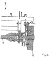
- Fig. 1 shows, can be arranged in a conventional manner around the bale chamber 2 around deflection means 3 for forming the bale, which may comprise circulating belts 4 and pulleys 5 in a conventional manner.
- a winding device 6 which comprises said wrapping material 12, for example in the form of a net and / or a foil and / or straps and / or straps and / or lacing - can insert into the bale forming chamber 2 so that the wrapping material 12 is wrapped around the bale.
- the winding device 6 may comprise a winding material storage 7, can be deducted from the wrapping material 12 and introduced into the bale forming chamber 2.
- the winding device 6 may include conveying means 10, for example in the form of conveyor rollers, which work in pairs and between which the wrapping material 12 is conveyed through. At least one of the mentioned conveyor rollers can in this case be driven by a suitable drive, for example in the form of an electric motor.
- the winding device 6 may further comprise pulleys 9 in order to specify the conveying path between the winding material storage 7 and the conveyor 10 can.
- Said wrapping material storage 7 may for example comprise a storage roller 8, on which the wrapping material 12 may be wound in a plurality of layers in the manner of a coil, so that the wrapping material 12 can be withdrawn from the wrapping material storage 7 by rotation of the storage roller 8.
- a braking device 13 which brakes the withdrawal of the wrapping material 12 from the wrapping material storage 7 or the conveying of the wrapping material and which can be associated with said wrapping material storage 7.
- the braking device 13 may be associated with the storage roller 8, on which the wrapping material 12 is wound to control the rotational resistance of said storage roller 7 and thus the resistance to the withdrawal of the wrapping material.
- the storage roller 8 can be rotatably mounted on an axle 19, wherein also the braking device 13, more precisely whose fixed part, can be arranged roratorisch stationary on the said axis 19, see.
- the rotatable part of the braking device 15 may be coupled to the storage roller 8 roratorisch.
- the braking device 13 is advantageously designed to be electrically operable or electrically working, wherein the braking device 13 in particular an electromagnetic Brake can be. Alternatively or additionally, however, the brake device 13 may also include an eddy current brake, a magnetic powder brake or a friction brake with an electric actuator.
- the braking device 13 can provide a variable braking force or a variable braking torque, wherein the braking device 13 is controlled by a control device 14, which controls the braking force as a function of at least one operating parameter of the baler 1, as already explained above.
- the mentioned control device 14 may in particular be an electronic control device, for example comprising a data processor and / or controller modules and / or control modules, and at least one determining device 15 for determining the said at least one operating parameter.
- Said determination means 15 may comprise a detection means 16 for detecting the winding material tension 12, wherein said winding material tension between the winding material storage 7 and the conveyor means 10 and / or before introducing the wrapping material into the bale forming chamber can be measured.
- the said detection device 16 can for this purpose have a dancer 18, for example in the form of a dancer roller, which is tensioned by means of a pretensioning device 21 against the winding material 12 to be pulled off.
- Said biasing device 21 may in this case have a direction of action which is transversely, in particular perpendicular to the conveying path of the wrapping material 12 and / or the surface of the wrapping material 12 and / or to a connecting plane, the two adjacent pulleys 9 connects aligned and said dancer in corresponding direction against the winding material surface 12 presses or pulls, see. Fig. 1 ,
- the dancer 18 may for example be pivotally mounted on a pivot arm 22, the pivot axis 23 may be aligned parallel to the axis of rotation of the adjacent pulleys 9.
- Said biasing device 21 may comprise, for example, a spring device which may be formed as a mechanical spring and / or gas spring or in other ways. Alternatively or additionally, a hydraulic cylinder, which can be acted upon by a corresponding pressure source, are used as a biasing device.
- the deflection ⁇ I of the dancer 18 can be detected by a sensor of the detection device 16 and taken from the control device 14 as a measure of the winding material tension or as an actual value of the winding material tension.
- the control device 14 may optionally carry out intermediate computing steps in order to calculate the winding material tension from the mentioned deflection value ⁇ I.
- control device 14 can control the braking device 13 in order to control the actual value as close as possible to a predefinable desired value of the winding material tension.
- the stated nominal value of the winding material tension may be a constant value, but alternatively may also be variable in the form of a variable winding material tension function over time and / or over the pull-off distance of the winding material.
- a constant winding material tension is desired, like this Fig. 3 shows, the braking torque M, which is applied by the braking device 13, with increasing diameter of the winding of the winding material 12 on the storage roller 8 are increasingly larger, that is for larger winding diameter a larger braking torque and smaller winding diameter is provided a smaller braking torque, wherein the braking torque can increase in proportion to the winding diameter.
- Fig. 3 shows the falling n line with increasing winding diameter on the layers of the winding material 12 the storage roller 8 at.
- the constant winding material tension is designated FNetz.
Landscapes
- Life Sciences & Earth Sciences (AREA)
- Environmental Sciences (AREA)
- Controlling Rewinding, Feeding, Winding, Or Abnormalities Of Webs (AREA)
Priority Applications (1)
| Application Number | Priority Date | Filing Date | Title |
|---|---|---|---|
| PL17151049T PL3199015T3 (pl) | 2016-01-28 | 2017-01-11 | Prasa do belowania |
Applications Claiming Priority (1)
| Application Number | Priority Date | Filing Date | Title |
|---|---|---|---|
| DE202016000568.6U DE202016000568U1 (de) | 2016-01-28 | 2016-01-28 | Ballenpresse |
Publications (2)
| Publication Number | Publication Date |
|---|---|
| EP3199015A1 EP3199015A1 (de) | 2017-08-02 |
| EP3199015B1 true EP3199015B1 (de) | 2019-07-17 |
Family
ID=57794158
Family Applications (1)
| Application Number | Title | Priority Date | Filing Date |
|---|---|---|---|
| EP17151049.8A Active EP3199015B1 (de) | 2016-01-28 | 2017-01-11 | Ballenpresse |
Country Status (3)
| Country | Link |
|---|---|
| EP (1) | EP3199015B1 (pl) |
| DE (1) | DE202016000568U1 (pl) |
| PL (1) | PL3199015T3 (pl) |
Cited By (1)
| Publication number | Priority date | Publication date | Assignee | Title |
|---|---|---|---|---|
| EP4338583A1 (de) * | 2022-08-29 | 2024-03-20 | Usines Claas France S.A.S | Verfahren zur regelung eines umwickelvorgangs |
Families Citing this family (7)
| Publication number | Priority date | Publication date | Assignee | Title |
|---|---|---|---|---|
| US10827685B2 (en) | 2017-08-11 | 2020-11-10 | Vermeer Manufacturing Company | Hydraulic brake for wrap material |
| WO2019038017A1 (en) | 2017-08-21 | 2019-02-28 | Kverneland Group Ravenna S.R.L. | METHOD FOR OPERATING A ROUND BALL PRESS, AND ROUND BALL PRESS |
| DE102019205330A1 (de) | 2019-04-12 | 2020-10-15 | Deere & Company | Ballenwickelvorrichtung für eine Rundballenpresse, Rundballenpresse und Verfahren zum Betreiben einer Rundballenpresse |
| US11589516B2 (en) | 2019-08-21 | 2023-02-28 | Cnh Industrial America Llc | Agricultural baler with controlled wrapping material brake |
| EP3932181A1 (en) * | 2020-07-01 | 2022-01-05 | AGCO Corporation | Twine tension control assembly |
| US11570952B2 (en) | 2021-05-13 | 2023-02-07 | Cnh Industrial America Llc | Agricultural baler with controlled wrapping material brake |
| US12302798B2 (en) | 2021-10-26 | 2025-05-20 | Agco Corporation | Twine tension monitoring apparatus |
Family Cites Families (11)
| Publication number | Priority date | Publication date | Assignee | Title |
|---|---|---|---|---|
| DE3702702A1 (de) * | 1986-02-27 | 1987-09-03 | Baer Maschf Josef | Regeleinrichtung fuer die fadenspannung bei wickelmaschinen, insbesondere in der faserwickeltechnik |
| DE10153517B4 (de) * | 2001-10-30 | 2011-01-27 | Deere & Company, Moline | Bindevorrichtung für eine Rundballenpresse |
| DE102007031187A1 (de) | 2007-07-04 | 2009-01-15 | Claas Selbstfahrende Erntemaschinen Gmbh | Rundballenpresse |
| US7908822B2 (en) * | 2008-05-15 | 2011-03-22 | Cnh America Llc | Computer controlled automatic wrapping material dispensing system for a round baler |
| BE1018706A3 (nl) * | 2009-03-30 | 2011-07-05 | Cnh Belgium Nv | Een methode voor het aansturen van een reminrichting en een ronde balenpers met een reminrichting. |
| US20120240527A1 (en) * | 2010-12-27 | 2012-09-27 | Agco Corporation | Baler Mesh Wrap Control With Tension Variance |
| US9706716B2 (en) * | 2012-08-21 | 2017-07-18 | Cnh Industrial America Llc | Current sensing of actuators on a round baler |
| DE102012017401A1 (de) * | 2012-09-03 | 2014-03-06 | Alois Pöttinger Maschinenfabrik Ges.m.b.H. | Landwirtschaftliche Maschine |
| DE102013007296B4 (de) | 2013-04-26 | 2015-12-31 | Maschinenfabrik Bernard Krone Gmbh | Press-Wickelkombination für Quaderballen |
| WO2015035368A2 (en) * | 2013-09-09 | 2015-03-12 | Forage Innovations B.V. | Round baler with dual wrapping rolls |
| DE202014003633U1 (de) | 2014-04-28 | 2015-07-30 | Alois Pöttinger Maschinenfabrik Ges.m.b.H. | Ballenpresse |
-
2016
- 2016-01-28 DE DE202016000568.6U patent/DE202016000568U1/de not_active Expired - Lifetime
-
2017
- 2017-01-11 PL PL17151049T patent/PL3199015T3/pl unknown
- 2017-01-11 EP EP17151049.8A patent/EP3199015B1/de active Active
Non-Patent Citations (1)
| Title |
|---|
| None * |
Cited By (2)
| Publication number | Priority date | Publication date | Assignee | Title |
|---|---|---|---|---|
| EP4338583A1 (de) * | 2022-08-29 | 2024-03-20 | Usines Claas France S.A.S | Verfahren zur regelung eines umwickelvorgangs |
| US12356896B2 (en) | 2022-08-29 | 2025-07-15 | Usines Claas France S.A.S | System and method for controlling a wrapping process |
Also Published As
| Publication number | Publication date |
|---|---|
| EP3199015A1 (de) | 2017-08-02 |
| PL3199015T3 (pl) | 2019-12-31 |
| DE202016000568U1 (de) | 2017-05-02 |
Similar Documents
| Publication | Publication Date | Title |
|---|---|---|
| EP3199015B1 (de) | Ballenpresse | |
| DE60224154T2 (de) | Vorrichtung zum Umhüllen von Körpern, insbesondere von Erntegutballen | |
| EP4338583B1 (de) | Verfahren zur regelung eines umwickelvorgangs | |
| DE2715988C2 (de) | Vorrichtung zum Steuern des Bandauftrages bei einer Schärmaschine | |
| DE2503423A1 (de) | Verfahren und vorrichtung zum oeffnen eines fadenkabels | |
| EP0391135B1 (de) | Verfahren zum Anwickeln von Bändern in Haspelanlagen | |
| DE10152162A1 (de) | Vorrichtung zum Transport von band- oder streifenförmigem Material | |
| DE19501982B4 (de) | Zuführvorrichtung einer diskontinuierlich bahnförmiges Material verarbeitenden Maschine | |
| DE20311822U1 (de) | Vorrichtung zum Regeln der Spannkraft eines umlaufenden Bandes | |
| EP0423067A1 (de) | Konusschärmaschine und Schärverfahren | |
| EP0534151B1 (de) | Verfahren und Vorrichtung zum Regeln der Bahnzugkraft einer Textilbahn | |
| EP1813145B1 (de) | Vorrichtung zum Umhüllen eines Ballens mit einer Hüllbahn und Ballenpresse | |
| EP0994975B1 (de) | Verfahren und vorrichtung zum schären mit einer konusschärmaschine | |
| EP2944716B1 (de) | Vorrichtung und verfahren zum beeinflussen der lage von knoten zwischen oberfaden und unterfaden beim nähen mit einer nähmaschine | |
| EP3123856B1 (de) | Press-wickelkombination zum pressen und umhüllen von rundballen | |
| EP1878333B1 (de) | Bindevorrichtung an landwirtschaftliche Rundballenpressen | |
| DE4241353C2 (de) | Tänzer für eine bahnförmiges Material verarbeitende Maschine | |
| DE4224454C2 (de) | Verfahren zur Regelung der Temperatur eines Heizmediums zur Erhitzung eines synthetischen Fadens und Texturiereinrichtung für einen synthetischen Faden | |
| DE69819861T2 (de) | Vorrichtung zum Liefern eines elastisch ausdehnbaren Fadens zu Strickmaschinen | |
| WO2012152526A1 (de) | Verfahren zum optimieren der förderung einer packstoffbahn im bereich einer schlauchformeinrichtung einer schlauchbeutelmaschine | |
| DE102011114434A1 (de) | Vorrichtung zum Transport von band- oder streifenförmigem Material | |
| DE102010046692B4 (de) | Dockenwickler zum Wickeln einer Warenbahn zu einer Docke | |
| EP1541008A1 (de) | Umwickeln mit nur einem Folienende | |
| EP1726548B1 (de) | Verfahren und eine Vorrichtung zum Regeln einer Bahnspannung einer laufenden Bahn in einer bahnverarbeitenden Vorrichtung | |
| DE102019135610A1 (de) | Vorrichtung und Verfahren zum Verarbeiten eines Polstermaterialstrangs und Polstermaterialwicklung |
Legal Events
| Date | Code | Title | Description |
|---|---|---|---|
| PUAI | Public reference made under article 153(3) epc to a published international application that has entered the european phase |
Free format text: ORIGINAL CODE: 0009012 |
|
| STAA | Information on the status of an ep patent application or granted ep patent |
Free format text: STATUS: THE APPLICATION HAS BEEN PUBLISHED |
|
| AK | Designated contracting states |
Kind code of ref document: A1 Designated state(s): AL AT BE BG CH CY CZ DE DK EE ES FI FR GB GR HR HU IE IS IT LI LT LU LV MC MK MT NL NO PL PT RO RS SE SI SK SM TR |
|
| AX | Request for extension of the european patent |
Extension state: BA ME |
|
| RIN1 | Information on inventor provided before grant (corrected) |
Inventor name: BUMBERGER, RAINER Inventor name: LACKNER, CHRISTIAN Inventor name: PRECHTL, WOLFGANG |
|
| STAA | Information on the status of an ep patent application or granted ep patent |
Free format text: STATUS: REQUEST FOR EXAMINATION WAS MADE |
|
| 17P | Request for examination filed |
Effective date: 20180129 |
|
| RBV | Designated contracting states (corrected) |
Designated state(s): AL AT BE BG CH CY CZ DE DK EE ES FI FR GB GR HR HU IE IS IT LI LT LU LV MC MK MT NL NO PL PT RO RS SE SI SK SM TR |
|
| STAA | Information on the status of an ep patent application or granted ep patent |
Free format text: STATUS: EXAMINATION IS IN PROGRESS |
|
| 17Q | First examination report despatched |
Effective date: 20180425 |
|
| GRAP | Despatch of communication of intention to grant a patent |
Free format text: ORIGINAL CODE: EPIDOSNIGR1 |
|
| STAA | Information on the status of an ep patent application or granted ep patent |
Free format text: STATUS: GRANT OF PATENT IS INTENDED |
|
| INTG | Intention to grant announced |
Effective date: 20190219 |
|
| GRAS | Grant fee paid |
Free format text: ORIGINAL CODE: EPIDOSNIGR3 |
|
| GRAA | (expected) grant |
Free format text: ORIGINAL CODE: 0009210 |
|
| STAA | Information on the status of an ep patent application or granted ep patent |
Free format text: STATUS: THE PATENT HAS BEEN GRANTED |
|
| AK | Designated contracting states |
Kind code of ref document: B1 Designated state(s): AL AT BE BG CH CY CZ DE DK EE ES FI FR GB GR HR HU IE IS IT LI LT LU LV MC MK MT NL NO PL PT RO RS SE SI SK SM TR |
|
| REG | Reference to a national code |
Ref country code: GB Ref legal event code: FG4D Free format text: NOT ENGLISH |
|
| REG | Reference to a national code |
Ref country code: CH Ref legal event code: EP |
|
| REG | Reference to a national code |
Ref country code: IE Ref legal event code: FG4D Free format text: LANGUAGE OF EP DOCUMENT: GERMAN |
|
| REG | Reference to a national code |
Ref country code: DE Ref legal event code: R096 Ref document number: 502017001761 Country of ref document: DE |
|
| REG | Reference to a national code |
Ref country code: AT Ref legal event code: REF Ref document number: 1154972 Country of ref document: AT Kind code of ref document: T Effective date: 20190815 |
|
| REG | Reference to a national code |
Ref country code: NL Ref legal event code: FP |
|
| REG | Reference to a national code |
Ref country code: LT Ref legal event code: MG4D |
|
| PG25 | Lapsed in a contracting state [announced via postgrant information from national office to epo] |
Ref country code: FI Free format text: LAPSE BECAUSE OF FAILURE TO SUBMIT A TRANSLATION OF THE DESCRIPTION OR TO PAY THE FEE WITHIN THE PRESCRIBED TIME-LIMIT Effective date: 20190717 Ref country code: NO Free format text: LAPSE BECAUSE OF FAILURE TO SUBMIT A TRANSLATION OF THE DESCRIPTION OR TO PAY THE FEE WITHIN THE PRESCRIBED TIME-LIMIT Effective date: 20191017 Ref country code: SE Free format text: LAPSE BECAUSE OF FAILURE TO SUBMIT A TRANSLATION OF THE DESCRIPTION OR TO PAY THE FEE WITHIN THE PRESCRIBED TIME-LIMIT Effective date: 20190717 Ref country code: PT Free format text: LAPSE BECAUSE OF FAILURE TO SUBMIT A TRANSLATION OF THE DESCRIPTION OR TO PAY THE FEE WITHIN THE PRESCRIBED TIME-LIMIT Effective date: 20191118 Ref country code: HR Free format text: LAPSE BECAUSE OF FAILURE TO SUBMIT A TRANSLATION OF THE DESCRIPTION OR TO PAY THE FEE WITHIN THE PRESCRIBED TIME-LIMIT Effective date: 20190717 Ref country code: LT Free format text: LAPSE BECAUSE OF FAILURE TO SUBMIT A TRANSLATION OF THE DESCRIPTION OR TO PAY THE FEE WITHIN THE PRESCRIBED TIME-LIMIT Effective date: 20190717 Ref country code: BG Free format text: LAPSE BECAUSE OF FAILURE TO SUBMIT A TRANSLATION OF THE DESCRIPTION OR TO PAY THE FEE WITHIN THE PRESCRIBED TIME-LIMIT Effective date: 20191017 |
|
| PG25 | Lapsed in a contracting state [announced via postgrant information from national office to epo] |
Ref country code: LV Free format text: LAPSE BECAUSE OF FAILURE TO SUBMIT A TRANSLATION OF THE DESCRIPTION OR TO PAY THE FEE WITHIN THE PRESCRIBED TIME-LIMIT Effective date: 20190717 Ref country code: AL Free format text: LAPSE BECAUSE OF FAILURE TO SUBMIT A TRANSLATION OF THE DESCRIPTION OR TO PAY THE FEE WITHIN THE PRESCRIBED TIME-LIMIT Effective date: 20190717 Ref country code: GR Free format text: LAPSE BECAUSE OF FAILURE TO SUBMIT A TRANSLATION OF THE DESCRIPTION OR TO PAY THE FEE WITHIN THE PRESCRIBED TIME-LIMIT Effective date: 20191018 Ref country code: RS Free format text: LAPSE BECAUSE OF FAILURE TO SUBMIT A TRANSLATION OF THE DESCRIPTION OR TO PAY THE FEE WITHIN THE PRESCRIBED TIME-LIMIT Effective date: 20190717 Ref country code: IS Free format text: LAPSE BECAUSE OF FAILURE TO SUBMIT A TRANSLATION OF THE DESCRIPTION OR TO PAY THE FEE WITHIN THE PRESCRIBED TIME-LIMIT Effective date: 20191117 Ref country code: ES Free format text: LAPSE BECAUSE OF FAILURE TO SUBMIT A TRANSLATION OF THE DESCRIPTION OR TO PAY THE FEE WITHIN THE PRESCRIBED TIME-LIMIT Effective date: 20190717 |
|
| PG25 | Lapsed in a contracting state [announced via postgrant information from national office to epo] |
Ref country code: TR Free format text: LAPSE BECAUSE OF FAILURE TO SUBMIT A TRANSLATION OF THE DESCRIPTION OR TO PAY THE FEE WITHIN THE PRESCRIBED TIME-LIMIT Effective date: 20190717 |
|
| PG25 | Lapsed in a contracting state [announced via postgrant information from national office to epo] |
Ref country code: DK Free format text: LAPSE BECAUSE OF FAILURE TO SUBMIT A TRANSLATION OF THE DESCRIPTION OR TO PAY THE FEE WITHIN THE PRESCRIBED TIME-LIMIT Effective date: 20190717 Ref country code: EE Free format text: LAPSE BECAUSE OF FAILURE TO SUBMIT A TRANSLATION OF THE DESCRIPTION OR TO PAY THE FEE WITHIN THE PRESCRIBED TIME-LIMIT Effective date: 20190717 Ref country code: RO Free format text: LAPSE BECAUSE OF FAILURE TO SUBMIT A TRANSLATION OF THE DESCRIPTION OR TO PAY THE FEE WITHIN THE PRESCRIBED TIME-LIMIT Effective date: 20190717 |
|
| PG25 | Lapsed in a contracting state [announced via postgrant information from national office to epo] |
Ref country code: IS Free format text: LAPSE BECAUSE OF FAILURE TO SUBMIT A TRANSLATION OF THE DESCRIPTION OR TO PAY THE FEE WITHIN THE PRESCRIBED TIME-LIMIT Effective date: 20200224 Ref country code: SM Free format text: LAPSE BECAUSE OF FAILURE TO SUBMIT A TRANSLATION OF THE DESCRIPTION OR TO PAY THE FEE WITHIN THE PRESCRIBED TIME-LIMIT Effective date: 20190717 Ref country code: SK Free format text: LAPSE BECAUSE OF FAILURE TO SUBMIT A TRANSLATION OF THE DESCRIPTION OR TO PAY THE FEE WITHIN THE PRESCRIBED TIME-LIMIT Effective date: 20190717 Ref country code: CZ Free format text: LAPSE BECAUSE OF FAILURE TO SUBMIT A TRANSLATION OF THE DESCRIPTION OR TO PAY THE FEE WITHIN THE PRESCRIBED TIME-LIMIT Effective date: 20190717 |
|
| REG | Reference to a national code |
Ref country code: DE Ref legal event code: R097 Ref document number: 502017001761 Country of ref document: DE |
|
| PLBE | No opposition filed within time limit |
Free format text: ORIGINAL CODE: 0009261 |
|
| STAA | Information on the status of an ep patent application or granted ep patent |
Free format text: STATUS: NO OPPOSITION FILED WITHIN TIME LIMIT |
|
| PG2D | Information on lapse in contracting state deleted |
Ref country code: IS |
|
| 26N | No opposition filed |
Effective date: 20200603 |
|
| PG25 | Lapsed in a contracting state [announced via postgrant information from national office to epo] |
Ref country code: SI Free format text: LAPSE BECAUSE OF FAILURE TO SUBMIT A TRANSLATION OF THE DESCRIPTION OR TO PAY THE FEE WITHIN THE PRESCRIBED TIME-LIMIT Effective date: 20190717 Ref country code: MC Free format text: LAPSE BECAUSE OF FAILURE TO SUBMIT A TRANSLATION OF THE DESCRIPTION OR TO PAY THE FEE WITHIN THE PRESCRIBED TIME-LIMIT Effective date: 20190717 |
|
| REG | Reference to a national code |
Ref country code: CH Ref legal event code: PL |
|
| REG | Reference to a national code |
Ref country code: BE Ref legal event code: MM Effective date: 20200131 |
|
| PG25 | Lapsed in a contracting state [announced via postgrant information from national office to epo] |
Ref country code: LU Free format text: LAPSE BECAUSE OF NON-PAYMENT OF DUE FEES Effective date: 20200111 |
|
| PG25 | Lapsed in a contracting state [announced via postgrant information from national office to epo] |
Ref country code: CH Free format text: LAPSE BECAUSE OF NON-PAYMENT OF DUE FEES Effective date: 20200131 Ref country code: LI Free format text: LAPSE BECAUSE OF NON-PAYMENT OF DUE FEES Effective date: 20200131 Ref country code: BE Free format text: LAPSE BECAUSE OF NON-PAYMENT OF DUE FEES Effective date: 20200131 |
|
| GBPC | Gb: european patent ceased through non-payment of renewal fee |
Effective date: 20210111 |
|
| PG25 | Lapsed in a contracting state [announced via postgrant information from national office to epo] |
Ref country code: GB Free format text: LAPSE BECAUSE OF NON-PAYMENT OF DUE FEES Effective date: 20210111 |
|
| PG25 | Lapsed in a contracting state [announced via postgrant information from national office to epo] |
Ref country code: MT Free format text: LAPSE BECAUSE OF FAILURE TO SUBMIT A TRANSLATION OF THE DESCRIPTION OR TO PAY THE FEE WITHIN THE PRESCRIBED TIME-LIMIT Effective date: 20190717 Ref country code: CY Free format text: LAPSE BECAUSE OF FAILURE TO SUBMIT A TRANSLATION OF THE DESCRIPTION OR TO PAY THE FEE WITHIN THE PRESCRIBED TIME-LIMIT Effective date: 20190717 |
|
| PG25 | Lapsed in a contracting state [announced via postgrant information from national office to epo] |
Ref country code: MK Free format text: LAPSE BECAUSE OF FAILURE TO SUBMIT A TRANSLATION OF THE DESCRIPTION OR TO PAY THE FEE WITHIN THE PRESCRIBED TIME-LIMIT Effective date: 20190717 |
|
| REG | Reference to a national code |
Ref country code: AT Ref legal event code: MM01 Ref document number: 1154972 Country of ref document: AT Kind code of ref document: T Effective date: 20220111 |
|
| PG25 | Lapsed in a contracting state [announced via postgrant information from national office to epo] |
Ref country code: AT Free format text: LAPSE BECAUSE OF NON-PAYMENT OF DUE FEES Effective date: 20220111 |
|
| P01 | Opt-out of the competence of the unified patent court (upc) registered |
Effective date: 20230613 |
|
| PGFP | Annual fee paid to national office [announced via postgrant information from national office to epo] |
Ref country code: NL Payment date: 20250121 Year of fee payment: 9 |
|
| PGFP | Annual fee paid to national office [announced via postgrant information from national office to epo] |
Ref country code: DE Payment date: 20250120 Year of fee payment: 9 |
|
| PGFP | Annual fee paid to national office [announced via postgrant information from national office to epo] |
Ref country code: IE Payment date: 20250129 Year of fee payment: 9 |
|
| PGFP | Annual fee paid to national office [announced via postgrant information from national office to epo] |
Ref country code: FR Payment date: 20250127 Year of fee payment: 9 |
|
| PGFP | Annual fee paid to national office [announced via postgrant information from national office to epo] |
Ref country code: IT Payment date: 20241209 Year of fee payment: 9 |
|
| PGFP | Annual fee paid to national office [announced via postgrant information from national office to epo] |
Ref country code: PL Payment date: 20251215 Year of fee payment: 10 |