EP3198339B1 - Überwachungsvorrichtung - Google Patents
Überwachungsvorrichtung Download PDFInfo
- Publication number
- EP3198339B1 EP3198339B1 EP15774661.1A EP15774661A EP3198339B1 EP 3198339 B1 EP3198339 B1 EP 3198339B1 EP 15774661 A EP15774661 A EP 15774661A EP 3198339 B1 EP3198339 B1 EP 3198339B1
- Authority
- EP
- European Patent Office
- Prior art keywords
- tape
- housing
- surveillance
- cambered
- cambered tape
- Prior art date
- Legal status (The legal status is an assumption and is not a legal conclusion. Google has not performed a legal analysis and makes no representation as to the accuracy of the status listed.)
- Active
Links
Images


Classifications
-
- G—PHYSICS
- G03—PHOTOGRAPHY; CINEMATOGRAPHY; ANALOGOUS TECHNIQUES USING WAVES OTHER THAN OPTICAL WAVES; ELECTROGRAPHY; HOLOGRAPHY
- G03B—APPARATUS OR ARRANGEMENTS FOR TAKING PHOTOGRAPHS OR FOR PROJECTING OR VIEWING THEM; APPARATUS OR ARRANGEMENTS EMPLOYING ANALOGOUS TECHNIQUES USING WAVES OTHER THAN OPTICAL WAVES; ACCESSORIES THEREFOR
- G03B17/00—Details of cameras or camera bodies; Accessories therefor
- G03B17/56—Accessories
- G03B17/561—Support related camera accessories
-
- B—PERFORMING OPERATIONS; TRANSPORTING
- B65—CONVEYING; PACKING; STORING; HANDLING THIN OR FILAMENTARY MATERIAL
- B65H—HANDLING THIN OR FILAMENTARY MATERIAL, e.g. SHEETS, WEBS, CABLES
- B65H75/00—Storing webs, tapes, or filamentary material, e.g. on reels
- B65H75/02—Cores, formers, supports, or holders for coiled, wound, or folded material, e.g. reels, spindles, bobbins, cop tubes, cans, mandrels or chucks
- B65H75/34—Cores, formers, supports, or holders for coiled, wound, or folded material, e.g. reels, spindles, bobbins, cop tubes, cans, mandrels or chucks specially adapted or mounted for storing and repeatedly paying-out and re-storing lengths of material provided for particular purposes, e.g. anchored hoses, power cables
- B65H75/38—Cores, formers, supports, or holders for coiled, wound, or folded material, e.g. reels, spindles, bobbins, cop tubes, cans, mandrels or chucks specially adapted or mounted for storing and repeatedly paying-out and re-storing lengths of material provided for particular purposes, e.g. anchored hoses, power cables involving the use of a core or former internal to, and supporting, a stored package of material
- B65H75/44—Constructional details
- B65H75/4418—Arrangements for stopping winding or unwinding; Arrangements for releasing the stop means
- B65H75/4428—Arrangements for stopping winding or unwinding; Arrangements for releasing the stop means acting on the reel or on a reel blocking mechanism
- B65H75/4431—Manual stop or release button
-
- F—MECHANICAL ENGINEERING; LIGHTING; HEATING; WEAPONS; BLASTING
- F16—ENGINEERING ELEMENTS AND UNITS; GENERAL MEASURES FOR PRODUCING AND MAINTAINING EFFECTIVE FUNCTIONING OF MACHINES OR INSTALLATIONS; THERMAL INSULATION IN GENERAL
- F16M—FRAMES, CASINGS OR BEDS OF ENGINES, MACHINES OR APPARATUS, NOT SPECIFIC TO ENGINES, MACHINES OR APPARATUS PROVIDED FOR ELSEWHERE; STANDS; SUPPORTS
- F16M11/00—Stands or trestles as supports for apparatus or articles placed thereon ; Stands for scientific apparatus such as gravitational force meters
- F16M11/02—Heads
- F16M11/04—Means for attachment of apparatus; Means allowing adjustment of the apparatus relatively to the stand
- F16M11/043—Allowing translations
- F16M11/046—Allowing translations adapted to upward-downward translation movement
-
- F—MECHANICAL ENGINEERING; LIGHTING; HEATING; WEAPONS; BLASTING
- F16—ENGINEERING ELEMENTS AND UNITS; GENERAL MEASURES FOR PRODUCING AND MAINTAINING EFFECTIVE FUNCTIONING OF MACHINES OR INSTALLATIONS; THERMAL INSULATION IN GENERAL
- F16M—FRAMES, CASINGS OR BEDS OF ENGINES, MACHINES OR APPARATUS, NOT SPECIFIC TO ENGINES, MACHINES OR APPARATUS PROVIDED FOR ELSEWHERE; STANDS; SUPPORTS
- F16M11/00—Stands or trestles as supports for apparatus or articles placed thereon ; Stands for scientific apparatus such as gravitational force meters
- F16M11/02—Heads
- F16M11/18—Heads with mechanism for moving the apparatus relatively to the stand
-
- F—MECHANICAL ENGINEERING; LIGHTING; HEATING; WEAPONS; BLASTING
- F16—ENGINEERING ELEMENTS AND UNITS; GENERAL MEASURES FOR PRODUCING AND MAINTAINING EFFECTIVE FUNCTIONING OF MACHINES OR INSTALLATIONS; THERMAL INSULATION IN GENERAL
- F16M—FRAMES, CASINGS OR BEDS OF ENGINES, MACHINES OR APPARATUS, NOT SPECIFIC TO ENGINES, MACHINES OR APPARATUS PROVIDED FOR ELSEWHERE; STANDS; SUPPORTS
- F16M11/00—Stands or trestles as supports for apparatus or articles placed thereon ; Stands for scientific apparatus such as gravitational force meters
- F16M11/20—Undercarriages with or without wheels
- F16M11/24—Undercarriages with or without wheels changeable in height or length of legs, also for transport only, e.g. by means of tubes screwed into each other
- F16M11/40—Undercarriages with or without wheels changeable in height or length of legs, also for transport only, e.g. by means of tubes screwed into each other by means of coilable or bendable legs or spiral shaped legs
-
- F—MECHANICAL ENGINEERING; LIGHTING; HEATING; WEAPONS; BLASTING
- F16—ENGINEERING ELEMENTS AND UNITS; GENERAL MEASURES FOR PRODUCING AND MAINTAINING EFFECTIVE FUNCTIONING OF MACHINES OR INSTALLATIONS; THERMAL INSULATION IN GENERAL
- F16M—FRAMES, CASINGS OR BEDS OF ENGINES, MACHINES OR APPARATUS, NOT SPECIFIC TO ENGINES, MACHINES OR APPARATUS PROVIDED FOR ELSEWHERE; STANDS; SUPPORTS
- F16M11/00—Stands or trestles as supports for apparatus or articles placed thereon ; Stands for scientific apparatus such as gravitational force meters
- F16M11/42—Stands or trestles as supports for apparatus or articles placed thereon ; Stands for scientific apparatus such as gravitational force meters with arrangement for propelling the support stands on wheels
-
- B—PERFORMING OPERATIONS; TRANSPORTING
- B65—CONVEYING; PACKING; STORING; HANDLING THIN OR FILAMENTARY MATERIAL
- B65H—HANDLING THIN OR FILAMENTARY MATERIAL, e.g. SHEETS, WEBS, CABLES
- B65H2701/00—Handled material; Storage means
- B65H2701/30—Handled filamentary material
- B65H2701/37—Tapes
- B65H2701/371—Curved tapes, e.g. "Spreizband"
-
- F—MECHANICAL ENGINEERING; LIGHTING; HEATING; WEAPONS; BLASTING
- F16—ENGINEERING ELEMENTS AND UNITS; GENERAL MEASURES FOR PRODUCING AND MAINTAINING EFFECTIVE FUNCTIONING OF MACHINES OR INSTALLATIONS; THERMAL INSULATION IN GENERAL
- F16M—FRAMES, CASINGS OR BEDS OF ENGINES, MACHINES OR APPARATUS, NOT SPECIFIC TO ENGINES, MACHINES OR APPARATUS PROVIDED FOR ELSEWHERE; STANDS; SUPPORTS
- F16M2200/00—Details of stands or supports
- F16M2200/02—Locking means
- F16M2200/025—Locking means for translational movement
Definitions
- the present invention relates to surveillance apparatus.
- Such supports have a telescopic mechanism for enabling the support to switch between a compressed and an extended condition.
- the supports include a retractable member comprising a series of coaxial tubular sub-members, each having decreasing girth compared to the preceding sub-member, and interconnected such that smaller girth sub-members may be sheathed inside their larger girth neighbours.
- a retractable member comprising a series of coaxial tubular sub-members, each having decreasing girth compared to the preceding sub-member, and interconnected such that smaller girth sub-members may be sheathed inside their larger girth neighbours.
- Such supports can extend to a length of approximately one metre.
- a surveillance apparatus comprising:- a retractable support member in the form of a cambered tape the member having a first end and a second end; a housing; a spooling mechanism mounted at the housing, and being rotatable relative to the housing, and being attached to the second end of the retractable support member, the spooling mechanism being: operable to rotate in a first direction to convert the retractable support member from a coiled condition to an extended condition and thereby pay-out the support member from the housing, operable to rotate in a second direction opposite to the first to convert the retractable support member from the extended condition to the coiled condition and thereby retract the support member into the housing; a mount attached to the first end of the retractable support member; a surveillance device attached to the mount for receiving environmental signals, a human interface remote from the surveillance device; and a signal interface for relaying the signals received at the surveillance device to the human interface, such that the surveillance device may be supported, remote from the human interface by paying out the member, and where
- Such a surveillance apparatus can tend to provide a lightweight support which offers the operator the option of using the surveillance device at a number of different displacements from the housing, and yet still provides for efficient stowage.
- Such a support member has been determined to provide efficient use of material in supporting the load of the surveillance device for low weight per unit length.
- the spooling mechanism may comprise a spring biased to retract the support member and wherein the surveillance apparatus further comprises a selectively applicable brake for locking the member in position when a desired amount of retractable support member has been converted into an extended condition.
- Such a spooling mechanism can tend to be convenient to operate. Further, the retraction of the support member, i.e. the tape, can be completed quickly by releasing the brake and allowing the spooling mechanism to retract the extended portion of the support member, as urged by the spring.
- the human interface is at the housing.
- the surveillance device may be a camera, and the human interface may be a display screen.
- the operator may monitor the output of the surveillance device remote from the surveillance device, either at the housing, or may be even on a non-contiguous human interface such as a separate tablet computer, which may be viewed by another operator.
- the display screen may be pivotally attached at the housing in at least one axis, such that the display screen may switch between a readily observable condition and a stowed condition.
- the electromagnetic signal may be a radio frequency signal having a frequency between 55GHz and 65GHz.
- Such frequencies can provide a relatively covert and secure wireless link.
- the signal interface may further comprise a receiver for receiving a second electromagnetic signal
- the human interface device may further comprise a transmitter for sending the second electromagnetic signal to the signal interface.
- signals such as control signals may be sent conveniently from the human operator to the surveillance device.
- the surveillance device is a video camera
- the operator may issue a command for the video camera to start recording, or stop recording.
- the housing may be man-portable and comprise a grip.
- the apparatus can more conveniently be used manually.
- the apparatus may be a handheld apparatus.
- the tape may be at least 30mm wide, have a camber radius of 15-25mm, and a thickness of 0.3-0.5mm.
- the tape is able to vertically support a device (e.g. camera) weighing approximately 1 Kg to a distance of up to approximately 3 m.
- a device e.g. camera
- the retractable support member may be provided with a low observable finish.
- the support member may be finished in a matt black paint and thereby mitigate the risk of glint.
- the transmitter (which may alternatively or additionally function as a receiver) at the surveillance device may further comprise an antenna arranged along a portion of the tape, and wherein the antenna is substantially planar and sufficiently flexible to be mounted on the tape to conform to the tape in both the coiled condition and the extended condition.
- the receiver (which may alternatively or additionally function as a transmitter) at the human interface may further comprise an antenna arranged along a portion of the tape, and wherein the antenna is substantially planar and sufficiently flexible to be mounted on the tape to conform to the tape in both the coiled condition and the extended condition.
- the surveillance device may further comprise an on-board power source.
- the surveillance device may comprise a releasable fastening whereby the device can be releasably fastened to the mount.
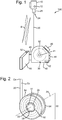
- FIG. 1 there is shown generally at 100 a surveillance apparatus.
- the surveillance apparatus 100 comprises a surveillance device 10, attached by way of a mount 25 to a first, or distal, end 24 of a retractable support member 20.
- the retractable support member 20 extends away from the surveillance device 10 into a rotatable spooling mechanism 30.
- the mechanism 30 is accommodated in a housing 40.
- the retractable support member 20 is generally rigid but may readily be collapsed by the application of a suitable force.
- the support 20 is generally in the form of a cambered metallic tape.
- the tape has a convex Cx and a concave Cc surface, as shown in Figure 2 .
- the tape 20 may be readily collapsed by applying a positive bending moment over the length of the tape (i.e. the bending moment tends to compress the concave surface and stretch the convex surface) and subsequently coiling the tape 20.
- the tape of the present embodiment is made from steel and has a thickness of 0.4mm, a width of 32mm and a camber radius of 20mm.
- a tape length of 3m may exist in the extended condition and feasibly support the surveillance device 10.
- the tape 20 may be 3m long.
- Such a tape 20 may alternatively be provided in a coiled condition (or a 'reeled-in' condition) where the tape 20 is wound in a spiral for more convenient stowage.
- the tape 20 may exist in a combination of conditions: an outer portion of the tape 20 may be provided in an extended condition and an inner portion of the tape 20 may be in a coiled condition.
- the camber of the tape 20 is arranged such that as the tape 20 is coiled, or reeled in, the concave surface Cc of the tape 20 tends to be laid on top of the convex Cx surface of the tape 20.
- the rotatable spooling mechanism 30 comprises a rotatable drum, rotatably mounted on an axle 41 within the housing 40.
- the drum is in the form of a reel or spool and comprises a generally hollow cylinder 32 (the axis 31 of which being coaxial with the axis of rotation of the drum) extending between flanking annular flanges 34.
- Within the hollow cylinder 32 there is a coil spring 36, formed from a strip of metal, which is at its innermost end 37 fixed to the housing 40.
- the coil spring 36 is wound around itself such that it spirals out from the innermost end 37, extending in a clockwise direction.
- the outermost end 38 of the coil spring 36 extends through an aperture in the cylinder 32 and is attached to the innermost end 22 of the tape 20.
- the innermost end 22 of the tape 20 is held close to the outer surface of the cylinder 32 and the concave surface Cc of the tape 20 faces the outer surface of the cylinder 32. From the innermost end 22 of the tape 20, the tape 20 extends in a clockwise manner, overlapping itself to form a spiral about the cylinder 32 and ultimately terminating at the distal end 24 of the tape 20.
- the coil spring 36 is biased to urge the outermost end 38 of the coil spring 36 back into the interior of the drum 32. Consequently the cylinder 32 is biased to rotate relative to the housing in an anticlockwise direction to reel in the tape 20.
- the biasing of the spring 36 and the interconnection between the spring's distal end 38 and the tape's inner end 22 tend to provide that the interconnection is in a substantially fixed location, relative to the cylinder 32.
- a brake 46 is provided which may be applied, by sliding into contact with the mechanism 30, so as to arrest the rotation of the drum and lock the amount of tape 20 paid out from the spooling mechanism 30.
- the spooling mechanism 30 is held within the chamber of the housing 40 such that it is able to rotate relative to the housing 40.
- the housing 40 is provided with an aperture to allow the retractable member, tape 20, to extend out from the general bounds of the housing 40.
- a human interface device 50 which in the present invention is a display screen 50, is attached to the housing 40 by hinge 45.
- the axis of the hinge 45 is oriented such that the display screen 50 may in one condition be folded into the main body of the housing 40 for secure stowage, or in another condition flipped out from the housing 40 for ease of viewing by an operator.
- the hinge 45 may be provided with a further pivot (not shown), having an axis normal to that of the hinge 45 such that the screen 50 may be tilted for even further ease of viewing by an operator.
- the housing 40 is further provided with a power supply 42 for providing power to electrical components at the housing 40, and a grip 44 for facilitating handheld operation of the apparatus.
- the surveillance device 10 is a video camera.
- surveillance device 10 is provided with an interface 12 for a wireless link S and is thereby capable of transmitting and/or receiving electromagnetic signals.
- the display screen 50 is provided with an interface 52 for the wireless link S and as such, images captured at the camera 10 may be relayed to the display screen 50 and shown thereon.
- the interfaces 12 and 52 may comprise an antenna and transceiver unit.
- the wireless link S may adopt RF transmission protocols included in or associated with BLUETOOTH® technology (including in particular the IEEE standard 802.15.1) or included in or associated with the IEEE 802.11 standards (referred to commonly as WIFI®). IEEE 802.11 standards would tend to be suited to relaying high definition video signals.
- the wireless link S may be operable at frequencies in the range of 55-65GHz and thereby enable high data rates and covert signal distribution (this band being strongly attenuated by air).
- the antenna is a flexible planar antenna laid up on the tape 20 (such that the antenna is conformal with the tape), and suitably insulated therefrom.
- a flexible planar antenna could be bonded or printed onto the tape 20.
- Such a flexible planar antenna should tend to roll up with the tape 20 as the tape 20 is stowed.
- a surveillance device not part of the present invention is shown generally at 200.
- the surveillance device 200 is similar to the first embodiment shown in Figure 1 . Consequently, for simplicity, where components are repeated such that reference numerals would be the same, these reference numerals have been omitted from Figure 3 for clarity.
- the surveillance apparatus 200 differs from the first embodiment in providing an alternative means for relaying signals (e.g. conveying data) from the surveillance device 10 (e.g. camera) to the human interface 50 (e.g. display screen).
- signals e.g. conveying data
- the surveillance device 10 e.g. camera
- human interface 50 e.g. display screen
- the apparatus 200 provides a continuous electrical connection between the device 10 and the display 50.
- This continuous connection comprises a coaxial cable 21 bonded to the tape 20 and thereby extending between the camera 10 and the housing 40.
- the coaxial cable 21 is bonded to the tape 20 using a thin single-sided adhesive strip 23 (omitted from Figure 5 for visual clarity) running along the tape 20.
- the coaxial cable 21 and adhesive strip 23 are selected to be sufficiently fine (i.e. having low profile) that they do not significantly impede the spooling mechanism 30, given that approximately 3m of tape (or more) may be coiled in the mechanism 30.
- the applicant has identified '38 AWG 50Ohm Coaxial Cable' as supplied by ADS Europe Ltd (ADS Europe Ltd, Clay House Business Centre, 5 Horninglow St, Burton-on-trent, DE14 1NG; info@adseuropeltd.com ) as being suitable for this purpose.
- the adhesive strip is a transparent adhesive laminate tape with a thickness of 0.05mm and cut to the width and length of the tape 20
- the surveillance apparatus 200 is provided with a rotary electrical joint, between the cylinder 32 and the housing 40 such that the signal carried over the coaxial cable 24 may be communicated onward to the display screen 50.
- the rotary electrical joint comprises annular tracks 47a and 47b on the outer surface of one of the flanges 34. These are electrically connected to the innermost end of the coaxial cable 21. More specifically: wire 43a connects the outer conductor of the cable 21 to the circular track 47a; and wire 43b connects the inner conductor of the cable 21 to the circular track 47b. (Wires 43a and 43b are omitted from Figure 3 for visual clarity).
- the wires 43a and 43b are physically routed within the mechanism 30 such that, with the exception of the innermost end 22 of the tape 20, they are secured away from the tape 20, and away from the coil spring 36. As such, the wires do not tangle with or otherwise contact these as the tape 20 pays out or reels in. Nonetheless, the wires are physically routed such that there is sufficient slack in them, particularly, where they contact the innermost end 22 so as to be able to accommodate shifts in the position of the innermost end 22 relative to the drum cylinder 32. However, the spring 37 of the spooling mechanism 30 is calibrated such that the innermost end 22 is substantially fixed relative to the cylinder 32; shifts in position should tend to be minimised.
- the housing 40 at the chamber that accommodates the spooling mechanism 30 is provided with sprung contacts 48a and 48b which are biased to touch their respective tracks 47a and 47b and thereby maintain contact as the spooling mechanism 30 rotates.
- the sprung contacts 48a, 48b are electrically connected to wires 49a and 49b which feed an input signal into the display screen 50.
- wires 43, the annular tracks 47 and the contacts 48 provide the rotary electrical joint and contribute to the continuous electrical connection between the device 10 and the human interface 50.
- axle 41 which is fixed to and forms part of the housing 40.
- the axle 41 protrudes through and supports the cylinder 32 of the spooling mechanism 30.
- Such support is provided at a low friction cylindrical interface 51 which facilitates the rotation of the spooling mechanism 30 about axis 31.
- the axle 41 is the part of the housing 40 to which the innermost end 37 of the spring 36 connects.
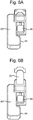
- the apparatus 100 or 200 may be in a collapsed condition where the tape 20 is fully retracted into the spooling mechanism, as shown in Figure 6A , so as to minimise the space the apparatus occupies.
- the apparatus can be readily stashed in a pocket or backpack.
- the apparatus 100 or 200 may be in an extended condition where the device 10 is remote to at least some degree from the human interface 50, as compared to when the apparatus is in the retracted condition and signals are being communicated therebetween. It is also noted that the camera may be activated and the apparatus generally in use, but without the need for the tape 20 to be extended and provide a different/displaced viewpoint.
- the apparatus 100 or 200 may readily be converted from such a storage condition into an extended condition, such as shown in Figures 1 , 3 , and 6B .
- the operator may simply disengage the brake 46 (if it is engaged) and then manually pay out the tape 20 to gradually displace the camera 10 from the housing 40.
- the operator overcomes the urging force of the spring 36 and causes the spooling mechanism 30 to rotate relative to the housing 40.
- the brake 46 may be reapplied in order to hold the camera 10 steady at that displacement and with the desired amount of tape in the extended condition.
- the operator may survey a scene by monitoring environmental signals from a viewpoint that could otherwise be unachievable.
- the apparatus 100, 200 may be extended in order to see over a wall or other obstacle.
- the apparatus 100, 200 may readily be converted from such an extended condition back to the storage condition by releasing the brake 46 and allowing the spring 36 to rotate the spooling mechanism 30 and thereby draw the tape 20 back into its coiled condition.
- Variants of the present invention may provide one or more of the following in combination or as an alternative to equivalents mentioned above.
- the human interface 50 may be a simple control panel for issuing blind instructions to the surveillance device 10.
- the control panel may be operable to issue a signal to the device 10 so as to start recording (where the device 10 is a video camera), or to capture and image (where the device 10 is a stills camera).
- Such a control panel may be suited to interfacing with the device 10 by means of a BLUETOOTH® scheme.
- the mount 25 may be provided in an articulated form, such that it may swivel and tilt. Such articulation may be passive so that the operator determines and applies the swivel and tilt whilst proximate to the device 10. Alternatively, the mount may be active such that in response to signals issued via the interface 50, the operator is able to swivel or tilt the device 10 e.g. to vary the field of view.
- the surveillance device has been embodied above as a camera or video camera.
- the device 10 may alternatively or additionally be capable of monitoring other environmental signals.
- the device may therefore comprise a microphone or a thermometer, or a magnetometer, or other sensor.
- the surveillance device 10 may be provided with an on board power supply, such as a battery and/or solar panel.
- an on board power supply such as a battery and/or solar panel.
- the provision of the detachable device 10 with on-board power supply enables a further mode of operation whereby the device 10 may be detached from the tape mount 25, deployed elsewhere and then, provided the wireless data link range is not exceeded, relay signals to the housing unit 40 and human interface device 50.
- the housing 40 may be provided with a motor or other actuator means for automatically reeling in or paying out of the tape 20. This provision would tend to enable one handed operation of the apparatus.
Landscapes
- Engineering & Computer Science (AREA)
- General Engineering & Computer Science (AREA)
- Mechanical Engineering (AREA)
- Physics & Mathematics (AREA)
- General Physics & Mathematics (AREA)
- Studio Devices (AREA)
- Burglar Alarm Systems (AREA)
Claims (13)
- Überwachungsgerät, umfassend:ein gewölbtes Band (20), das ein erstes Ende und ein zweites Ende aufweist,eine Halterung (25), die an dem ersten Ende des gewölbten Bandes angebracht ist;eine Überwachungsvorrichtung (10), die an der Halterung angebracht ist, um Umgebungssignale zu, empfangen,eine menschliche Schnittstelle (52), die von der Überwachungsvorrichtung entfernt ist,eine Signalschnittstelle (12) am ersten Ende, um die Signale, die an der Überwachungsvorrichtung empfangen werden, an die menschliche Schnittstelle weiterzuleiten,ein Gehäuse (40), undeinen Wickelmechanismus (30), der an dem Gehäuse montiert ist und mit Bezug auf das Gehäuse drehbar ist und an dem zweiten Ende des gewölbten Bandes angebracht ist, wobei der Wickelmechanismus: betriebsfähig ist, um sich in einer ersten Richtung zu drehen, um das gewölbte Band von einem aufgerollten Zustand in einen abgerollten Zustand zu versetzen und dadurch das gewölbte Band aus dem Gehäuse ablaufen zu lassen, und betriebsfähig ist, um sich in einer zweiten Richtung zu drehen, die zu der ersten entgegengesetzt ist, um das gewölbte Band von dem abgerollten Zustand in den aufgerollten Zustand zu versetzen und dadurch das gewölbte Band in das Gehäuse zurückzuziehen;so dass die Überwachungsvorrichtung (10) von der menschlichen Schnittstelle entfernt durch Ablaufenlassen des gewölbten Bandes (20) getragen werden kann,und wobei die Signalschnittstelle (12) einen Sender an der Überwachungsvorrichtung umfasst, und die menschliche Schnittstelle (52) einen Empfänger zum Empfangen des ersten elektromagnetischen Signals umfasst,dadurch gekennzeichnet, dass die Signalschnittstelle (12) ferner eine Antenne zum Senden eines ersten elektromagnetischen Signals umfasst und entlang eines Abschnitts des gewölbten Bandes angeordnet ist, und wobei die Antenne im Wesentlichen eben und biegsam genug ist, um an dem gewölbten Band montiert zu sein, um sich dem gewölbten Band sowohl im aufgerollten Zustand als auch im abgerollten Zustand anzupassen.
- Überwachungsgerät, umfassend:ein gewölbtes Band (20), das ein erstes Ende und ein zweites Ende aufweist,eine Halterung (25), die an dem ersten Ende des gewölbten Bandes angebracht ist;eine Überwachungsvorrichtung (10), die an der Halterung angebracht ist, um Umgebungssignale zu empfangen,eine menschliche Schnittstelle (52), die von der Überwachungsvorrichtung entfernt ist,eine Signalschnittstelle (12) am ersten Ende, um die Signale, die an der Überwachungsvorrichtung empfangen werden, an die menschliche Schnittstelle weiterzuleiten,ein Gehäuse (40), undeinen Wickelmechanismus (30), der an dem Gehäuse montiert ist und mit Bezug auf das Gehäuse drehbar ist und an dem zweiten Ende des gewölbten Bandes angebracht ist, wobei der Wickelmechanismus: betriebsfähig ist, um sich in einer ersten Richtung zu drehen, um das gewölbte Band von einem aufgerollten Zustand in einen abgerollten Zustand zu versetzen und dadurch das gewölbte Band aus dem Gehäuse ablaufen zu lassen, und betriebsfähig ist, um sich in einer zweiten Richtung zu drehen, die zu der ersten entgegengesetzt ist, um das gewölbte Band von dem abgerollten Zustand in den aufgerollten Zustand zu versetzen und dadurch das gewölbte Band in das Gehäuse zurückzuziehen;so dass die Überwachungsvorrichtung (10) von der menschlichen Schnittstelle entfernt durch Ablaufenlassen des gewölbten Bandes (20) getragen werden kann,und wobei die Signalschnittstelle (12) einen Sender an der Überwachungsvorrichtung umfasst, und die menschliche Schnittstelle (52) einen Empfänger zum Empfangen des ersten elektromagnetischen Signals umfasst,dadurch gekennzeichnet, dass die menschliche Schnittstelle (52) an dem Gehäuse (40) angebracht ist und ferner eine Antenne umfasst, die entlang eines Abschnitts des gewölbten Bandes angeordnet ist, und wobei die Antenne im Wesentlichen eben und biegsam genug ist, um an dem gewölbten Band montiert zu sein, um sich dem gewölbten Band sowohl im aufgerollten Zustand als auch im abgerollten Zustand anzupassen.
- Überwachungsgerät nach einem der vorhergehenden Ansprüche, wobei:der Wickelmechanismus (30) eine Feder umfasst, die vorgespannt ist, um das gewölbte Band zurückzuziehen,und wobei das Überwachungsgerät ferner eine selektiv anziehbare Bremse (46) umfasst, um das gewölbte Band an Ort und Stelle zu blockieren, wenn eine gewünschte Menge des gewölbten Bandes in einen abgerollten Zustand versetzt wurde.
- Überwachungsgerät nach Anspruch 1 oder 3, wobei sich die menschliche Schnittstelle an dem Gehäuse befindet.
- Überwachungsgerät nach einem der vorhergehenden Ansprüche, wobei:die Überwachungsvorrichtung eine Kamera ist, unddie menschliche Schnittstelle ein Anzeigebildschirm ist.
- Überwachungsgerät nach einem der vorhergehenden Ansprüche, wobei der Anzeigebildschirm an dem Gehäuse um mindestens eine Achse schwenkbar angebracht ist, so dass der Anzeigebildschirm zwischen einem leicht zu beobachtenden Zustand und einem aufgeräumten Zustand wechseln kann.
- Überwachungsgerät nach einem der vorhergehenden Ansprüche, wobei das drahtlose Signal ein Funkfrequenzsignal ist, das eine Frequenz zwischen 55 GHz und 65 GHz aufweist.
- Überwachungsvorrichtung nach einem der vorhergehenden Ansprüche, wobei die Signalschnittstelle ferner einen Empfänger zum Empfangen eines zweiten elektromagnetischen Signals umfasst, und wobei die menschliche Schnittstellenvorrichtung einen Sender zum Senden des zweiten elektromagnetischen Signals an die Signalschnittstelle umfasst.
- Überwachungsgerät nach einem der vorhergehenden Ansprüche, wobei das Gehäuse tragbar ist und einen Griff umfasst.
- Überwachungsgerät nach Anspruch 3, wobei das gewölbte Band mindestens 30 mm breit ist, einen Wölbungsradius von 15 bis 25 mm und eine Dicke von 0,3 bis 0,5 mm aufweist.
- Überwachungsgerät nach einem der vorhergehenden Ansprüche, wobei das gewölbte Band mit einer Stealth-Oberflächenbehandlung versehen ist.
- Überwachungsgerät nach einem der vorhergehenden Ansprüche, wobei die Überwachungsvorrichtung ferner eine bordeigene Energiequelle (42) umfasst.
- Überwachungsgerät nach einem der vorhergehenden Ansprüche, wobei die Überwachungsvorrichtung ein lösbares Befestigungsmittel umfasst, mit dem die Vorrichtung an der Halterung lösbar befestigt ist.
Applications Claiming Priority (2)
| Application Number | Priority Date | Filing Date | Title |
|---|---|---|---|
| GB1416926.2A GB2530534B (en) | 2014-09-25 | 2014-09-25 | Surveillance apparatus |
| PCT/GB2015/052762 WO2016046552A1 (en) | 2014-09-25 | 2015-09-24 | Surveillance apparatus |
Publications (2)
| Publication Number | Publication Date |
|---|---|
| EP3198339A1 EP3198339A1 (de) | 2017-08-02 |
| EP3198339B1 true EP3198339B1 (de) | 2019-12-04 |
Family
ID=51901099
Family Applications (1)
| Application Number | Title | Priority Date | Filing Date |
|---|---|---|---|
| EP15774661.1A Active EP3198339B1 (de) | 2014-09-25 | 2015-09-24 | Überwachungsvorrichtung |
Country Status (6)
| Country | Link |
|---|---|
| US (1) | US10087039B2 (de) |
| EP (1) | EP3198339B1 (de) |
| AU (1) | AU2015323594B2 (de) |
| CA (1) | CA2962345C (de) |
| GB (1) | GB2530534B (de) |
| WO (1) | WO2016046552A1 (de) |
Families Citing this family (4)
| Publication number | Priority date | Publication date | Assignee | Title |
|---|---|---|---|---|
| GB2530534B (en) | 2014-09-25 | 2021-06-02 | Bae Systems Plc | Surveillance apparatus |
| GB2530535B (en) | 2014-09-25 | 2021-04-07 | Bae Systems Plc | Surveillance apparatus |
| FR3055325B1 (fr) * | 2016-08-26 | 2018-08-31 | Nexans | Touret de cable de transport d’electricite connecte |
| US20190323653A1 (en) * | 2018-04-24 | 2019-10-24 | Jordan B. Pollack | Portable and extendable support and mounting system utilizing a plurality of support mechanisms |
Family Cites Families (20)
| Publication number | Priority date | Publication date | Assignee | Title |
|---|---|---|---|---|
| US3319987A (en) | 1965-10-19 | 1967-05-16 | Thiokol Chemical Corp | Extensible boom |
| US6112474A (en) * | 1998-01-27 | 2000-09-05 | Paine; David L. | Retractable web column |
| DE29819849U1 (de) * | 1998-11-06 | 1999-05-27 | Jezewski, Frank, 52062 Aachen | Druckschlauchstativ |
| US20020180866A1 (en) * | 2001-05-29 | 2002-12-05 | Monroe David A. | Modular sensor array |
| US7184086B2 (en) | 2002-02-25 | 2007-02-27 | Konica Corporation | Camera having flexible display |
| NL1022062C1 (nl) | 2002-12-03 | 2004-06-07 | Zho Innovations B V | Kabelhaspel. |
| US20110012003A1 (en) * | 2005-04-19 | 2011-01-20 | Geo Systems, Inc. | Apparatus and methods for providing a retractible mast |
| US20060261207A1 (en) * | 2005-04-19 | 2006-11-23 | Woodruff Christopher D | Apparatus and methods for providing a retractable mast |
| US7343828B2 (en) | 2006-05-30 | 2008-03-18 | The Coca-Cola Company | Tape fed miniature air gap inspection crawler |
| US20090003822A1 (en) * | 2007-06-27 | 2009-01-01 | Frank Tyner | Hand-held photographic support system |
| EP2110678B1 (de) | 2008-04-14 | 2014-05-07 | Alstom Technology Ltd | Vorrichtung zur Inspektion eines Spaltes |
| WO2011000092A1 (en) * | 2009-06-29 | 2011-01-06 | Matthew Hunsberger | A disc brake for a tape measure |
| GB2474246B (en) | 2009-10-07 | 2012-02-08 | Alstom Technology Ltd | Apparatus for inspection of a gap |
| US20110243551A1 (en) * | 2010-04-05 | 2011-10-06 | Stanfield Young | Camera-steadying device |
| US20120112008A1 (en) * | 2010-08-16 | 2012-05-10 | Primal Innovation | System for high altitude tethered powered flight platform |
| ES2557981T3 (es) * | 2011-04-22 | 2016-02-01 | Westinghouse Electric Company Llc | Sistema robótico de inspección submarina |
| US20130233964A1 (en) * | 2012-03-07 | 2013-09-12 | Aurora Flight Sciences Corporation | Tethered aerial system for data gathering |
| US9238572B2 (en) * | 2013-03-15 | 2016-01-19 | Tethers Unlimited Inc. | Orbital winch |
| GB2530534B (en) | 2014-09-25 | 2021-06-02 | Bae Systems Plc | Surveillance apparatus |
| GB2530535B (en) | 2014-09-25 | 2021-04-07 | Bae Systems Plc | Surveillance apparatus |
-
2014
- 2014-09-25 GB GB1416926.2A patent/GB2530534B/en active Active
-
2015
- 2015-09-24 AU AU2015323594A patent/AU2015323594B2/en active Active
- 2015-09-24 CA CA2962345A patent/CA2962345C/en active Active
- 2015-09-24 EP EP15774661.1A patent/EP3198339B1/de active Active
- 2015-09-24 WO PCT/GB2015/052762 patent/WO2016046552A1/en not_active Ceased
- 2015-09-24 US US15/514,245 patent/US10087039B2/en active Active
Non-Patent Citations (1)
| Title |
|---|
| None * |
Also Published As
| Publication number | Publication date |
|---|---|
| US10087039B2 (en) | 2018-10-02 |
| AU2015323594A1 (en) | 2017-04-13 |
| EP3198339A1 (de) | 2017-08-02 |
| GB2530534A (en) | 2016-03-30 |
| AU2015323594B2 (en) | 2021-05-06 |
| CA2962345C (en) | 2023-03-21 |
| US20170291791A1 (en) | 2017-10-12 |
| WO2016046552A1 (en) | 2016-03-31 |
| CA2962345A1 (en) | 2016-03-31 |
| GB2530534B (en) | 2021-06-02 |
| GB201416926D0 (en) | 2014-11-12 |
Similar Documents
| Publication | Publication Date | Title |
|---|---|---|
| AU2019232839B2 (en) | Surveillance apparatus | |
| CA2962345C (en) | Surveillance apparatus | |
| US12306524B1 (en) | Multi-dielectric coaxial push-cables and associated apparatus | |
| US11325702B2 (en) | Tethered aerial drone system | |
| US11136215B2 (en) | Tether cable spooling apparatus | |
| US20230038357A1 (en) | Inward sloped drum face for pipe inspection camera system | |
| EP1934628A2 (de) | Banddurchgangs-bildgebungseinrichtung | |
| US20110054690A1 (en) | Electro-mechanism for extending the capabilities of bilateral robotic platforms and a method for performing the same | |
| CN109533154B (zh) | 滑板车 | |
| JP2002271674A (ja) | 広帯域無線周波数トランシーバが組み込まれたデジタルカメラ用のアンテナ装置 | |
| JPH0336802A (ja) | 展開型アンテナベイ | |
| US20210313668A1 (en) | Antenna System | |
| EP3516748B1 (de) | Verbesserte überwachungsvorrichtung | |
| US5835070A (en) | Retractable antenna | |
| EP3300198A1 (de) | Verbesserte überwachungsvorrichtung | |
| US20240167608A1 (en) | Linked cable-handling and cable-storage drum devices and systems for the coordinated movement of a push-cable | |
| GB2554351A (en) | Improved surveillance apparatus | |
| NL2010540C2 (en) | Battery charging unit having an extractable carrier tape for its wiring. | |
| CN109204856B (zh) | 云台及具有此云台的无人机 | |
| JP2004067354A (ja) | ブーム長さ検出装置 |
Legal Events
| Date | Code | Title | Description |
|---|---|---|---|
| STAA | Information on the status of an ep patent application or granted ep patent |
Free format text: STATUS: THE INTERNATIONAL PUBLICATION HAS BEEN MADE |
|
| PUAI | Public reference made under article 153(3) epc to a published international application that has entered the european phase |
Free format text: ORIGINAL CODE: 0009012 |
|
| STAA | Information on the status of an ep patent application or granted ep patent |
Free format text: STATUS: REQUEST FOR EXAMINATION WAS MADE |
|
| 17P | Request for examination filed |
Effective date: 20170327 |
|
| AK | Designated contracting states |
Kind code of ref document: A1 Designated state(s): AL AT BE BG CH CY CZ DE DK EE ES FI FR GB GR HR HU IE IS IT LI LT LU LV MC MK MT NL NO PL PT RO RS SE SI SK SM TR |
|
| AX | Request for extension of the european patent |
Extension state: BA ME |
|
| DAV | Request for validation of the european patent (deleted) | ||
| DAX | Request for extension of the european patent (deleted) | ||
| GRAP | Despatch of communication of intention to grant a patent |
Free format text: ORIGINAL CODE: EPIDOSNIGR1 |
|
| STAA | Information on the status of an ep patent application or granted ep patent |
Free format text: STATUS: GRANT OF PATENT IS INTENDED |
|
| INTG | Intention to grant announced |
Effective date: 20190712 |
|
| GRAS | Grant fee paid |
Free format text: ORIGINAL CODE: EPIDOSNIGR3 |
|
| GRAA | (expected) grant |
Free format text: ORIGINAL CODE: 0009210 |
|
| STAA | Information on the status of an ep patent application or granted ep patent |
Free format text: STATUS: THE PATENT HAS BEEN GRANTED |
|
| AK | Designated contracting states |
Kind code of ref document: B1 Designated state(s): AL AT BE BG CH CY CZ DE DK EE ES FI FR GB GR HR HU IE IS IT LI LT LU LV MC MK MT NL NO PL PT RO RS SE SI SK SM TR |
|
| REG | Reference to a national code |
Ref country code: GB Ref legal event code: FG4D |
|
| REG | Reference to a national code |
Ref country code: CH Ref legal event code: EP |
|
| REG | Reference to a national code |
Ref country code: AT Ref legal event code: REF Ref document number: 1210125 Country of ref document: AT Kind code of ref document: T Effective date: 20191215 |
|
| REG | Reference to a national code |
Ref country code: DE Ref legal event code: R096 Ref document number: 602015043030 Country of ref document: DE |
|
| REG | Reference to a national code |
Ref country code: IE Ref legal event code: FG4D |
|
| REG | Reference to a national code |
Ref country code: NL Ref legal event code: MP Effective date: 20191204 |
|
| REG | Reference to a national code |
Ref country code: LT Ref legal event code: MG4D |
|
| PG25 | Lapsed in a contracting state [announced via postgrant information from national office to epo] |
Ref country code: GR Free format text: LAPSE BECAUSE OF FAILURE TO SUBMIT A TRANSLATION OF THE DESCRIPTION OR TO PAY THE FEE WITHIN THE PRESCRIBED TIME-LIMIT Effective date: 20200305 Ref country code: NO Free format text: LAPSE BECAUSE OF FAILURE TO SUBMIT A TRANSLATION OF THE DESCRIPTION OR TO PAY THE FEE WITHIN THE PRESCRIBED TIME-LIMIT Effective date: 20200304 Ref country code: FI Free format text: LAPSE BECAUSE OF FAILURE TO SUBMIT A TRANSLATION OF THE DESCRIPTION OR TO PAY THE FEE WITHIN THE PRESCRIBED TIME-LIMIT Effective date: 20191204 Ref country code: LT Free format text: LAPSE BECAUSE OF FAILURE TO SUBMIT A TRANSLATION OF THE DESCRIPTION OR TO PAY THE FEE WITHIN THE PRESCRIBED TIME-LIMIT Effective date: 20191204 Ref country code: BG Free format text: LAPSE BECAUSE OF FAILURE TO SUBMIT A TRANSLATION OF THE DESCRIPTION OR TO PAY THE FEE WITHIN THE PRESCRIBED TIME-LIMIT Effective date: 20200304 Ref country code: SE Free format text: LAPSE BECAUSE OF FAILURE TO SUBMIT A TRANSLATION OF THE DESCRIPTION OR TO PAY THE FEE WITHIN THE PRESCRIBED TIME-LIMIT Effective date: 20191204 Ref country code: LV Free format text: LAPSE BECAUSE OF FAILURE TO SUBMIT A TRANSLATION OF THE DESCRIPTION OR TO PAY THE FEE WITHIN THE PRESCRIBED TIME-LIMIT Effective date: 20191204 |
|
| PG25 | Lapsed in a contracting state [announced via postgrant information from national office to epo] |
Ref country code: RS Free format text: LAPSE BECAUSE OF FAILURE TO SUBMIT A TRANSLATION OF THE DESCRIPTION OR TO PAY THE FEE WITHIN THE PRESCRIBED TIME-LIMIT Effective date: 20191204 Ref country code: HR Free format text: LAPSE BECAUSE OF FAILURE TO SUBMIT A TRANSLATION OF THE DESCRIPTION OR TO PAY THE FEE WITHIN THE PRESCRIBED TIME-LIMIT Effective date: 20191204 |
|
| PG25 | Lapsed in a contracting state [announced via postgrant information from national office to epo] |
Ref country code: AL Free format text: LAPSE BECAUSE OF FAILURE TO SUBMIT A TRANSLATION OF THE DESCRIPTION OR TO PAY THE FEE WITHIN THE PRESCRIBED TIME-LIMIT Effective date: 20191204 |
|
| PG25 | Lapsed in a contracting state [announced via postgrant information from national office to epo] |
Ref country code: ES Free format text: LAPSE BECAUSE OF FAILURE TO SUBMIT A TRANSLATION OF THE DESCRIPTION OR TO PAY THE FEE WITHIN THE PRESCRIBED TIME-LIMIT Effective date: 20191204 Ref country code: EE Free format text: LAPSE BECAUSE OF FAILURE TO SUBMIT A TRANSLATION OF THE DESCRIPTION OR TO PAY THE FEE WITHIN THE PRESCRIBED TIME-LIMIT Effective date: 20191204 Ref country code: PT Free format text: LAPSE BECAUSE OF FAILURE TO SUBMIT A TRANSLATION OF THE DESCRIPTION OR TO PAY THE FEE WITHIN THE PRESCRIBED TIME-LIMIT Effective date: 20200429 Ref country code: RO Free format text: LAPSE BECAUSE OF FAILURE TO SUBMIT A TRANSLATION OF THE DESCRIPTION OR TO PAY THE FEE WITHIN THE PRESCRIBED TIME-LIMIT Effective date: 20191204 Ref country code: CZ Free format text: LAPSE BECAUSE OF FAILURE TO SUBMIT A TRANSLATION OF THE DESCRIPTION OR TO PAY THE FEE WITHIN THE PRESCRIBED TIME-LIMIT Effective date: 20191204 Ref country code: NL Free format text: LAPSE BECAUSE OF FAILURE TO SUBMIT A TRANSLATION OF THE DESCRIPTION OR TO PAY THE FEE WITHIN THE PRESCRIBED TIME-LIMIT Effective date: 20191204 |
|
| PG25 | Lapsed in a contracting state [announced via postgrant information from national office to epo] |
Ref country code: SM Free format text: LAPSE BECAUSE OF FAILURE TO SUBMIT A TRANSLATION OF THE DESCRIPTION OR TO PAY THE FEE WITHIN THE PRESCRIBED TIME-LIMIT Effective date: 20191204 Ref country code: SK Free format text: LAPSE BECAUSE OF FAILURE TO SUBMIT A TRANSLATION OF THE DESCRIPTION OR TO PAY THE FEE WITHIN THE PRESCRIBED TIME-LIMIT Effective date: 20191204 Ref country code: IS Free format text: LAPSE BECAUSE OF FAILURE TO SUBMIT A TRANSLATION OF THE DESCRIPTION OR TO PAY THE FEE WITHIN THE PRESCRIBED TIME-LIMIT Effective date: 20200404 |
|
| REG | Reference to a national code |
Ref country code: DE Ref legal event code: R097 Ref document number: 602015043030 Country of ref document: DE |
|
| REG | Reference to a national code |
Ref country code: AT Ref legal event code: MK05 Ref document number: 1210125 Country of ref document: AT Kind code of ref document: T Effective date: 20191204 |
|
| PLBE | No opposition filed within time limit |
Free format text: ORIGINAL CODE: 0009261 |
|
| STAA | Information on the status of an ep patent application or granted ep patent |
Free format text: STATUS: NO OPPOSITION FILED WITHIN TIME LIMIT |
|
| PG25 | Lapsed in a contracting state [announced via postgrant information from national office to epo] |
Ref country code: DK Free format text: LAPSE BECAUSE OF FAILURE TO SUBMIT A TRANSLATION OF THE DESCRIPTION OR TO PAY THE FEE WITHIN THE PRESCRIBED TIME-LIMIT Effective date: 20191204 |
|
| 26N | No opposition filed |
Effective date: 20200907 |
|
| PG25 | Lapsed in a contracting state [announced via postgrant information from national office to epo] |
Ref country code: AT Free format text: LAPSE BECAUSE OF FAILURE TO SUBMIT A TRANSLATION OF THE DESCRIPTION OR TO PAY THE FEE WITHIN THE PRESCRIBED TIME-LIMIT Effective date: 20191204 Ref country code: PL Free format text: LAPSE BECAUSE OF FAILURE TO SUBMIT A TRANSLATION OF THE DESCRIPTION OR TO PAY THE FEE WITHIN THE PRESCRIBED TIME-LIMIT Effective date: 20191204 Ref country code: SI Free format text: LAPSE BECAUSE OF FAILURE TO SUBMIT A TRANSLATION OF THE DESCRIPTION OR TO PAY THE FEE WITHIN THE PRESCRIBED TIME-LIMIT Effective date: 20191204 |
|
| PG25 | Lapsed in a contracting state [announced via postgrant information from national office to epo] |
Ref country code: IT Free format text: LAPSE BECAUSE OF FAILURE TO SUBMIT A TRANSLATION OF THE DESCRIPTION OR TO PAY THE FEE WITHIN THE PRESCRIBED TIME-LIMIT Effective date: 20191204 |
|
| PG25 | Lapsed in a contracting state [announced via postgrant information from national office to epo] |
Ref country code: MC Free format text: LAPSE BECAUSE OF FAILURE TO SUBMIT A TRANSLATION OF THE DESCRIPTION OR TO PAY THE FEE WITHIN THE PRESCRIBED TIME-LIMIT Effective date: 20191204 |
|
| REG | Reference to a national code |
Ref country code: CH Ref legal event code: PL |
|
| REG | Reference to a national code |
Ref country code: BE Ref legal event code: MM Effective date: 20200930 |
|
| PG25 | Lapsed in a contracting state [announced via postgrant information from national office to epo] |
Ref country code: LU Free format text: LAPSE BECAUSE OF NON-PAYMENT OF DUE FEES Effective date: 20200924 |
|
| PG25 | Lapsed in a contracting state [announced via postgrant information from national office to epo] |
Ref country code: CH Free format text: LAPSE BECAUSE OF NON-PAYMENT OF DUE FEES Effective date: 20200930 Ref country code: BE Free format text: LAPSE BECAUSE OF NON-PAYMENT OF DUE FEES Effective date: 20200930 Ref country code: LI Free format text: LAPSE BECAUSE OF NON-PAYMENT OF DUE FEES Effective date: 20200930 Ref country code: IE Free format text: LAPSE BECAUSE OF NON-PAYMENT OF DUE FEES Effective date: 20200924 |
|
| PG25 | Lapsed in a contracting state [announced via postgrant information from national office to epo] |
Ref country code: TR Free format text: LAPSE BECAUSE OF FAILURE TO SUBMIT A TRANSLATION OF THE DESCRIPTION OR TO PAY THE FEE WITHIN THE PRESCRIBED TIME-LIMIT Effective date: 20191204 Ref country code: MT Free format text: LAPSE BECAUSE OF FAILURE TO SUBMIT A TRANSLATION OF THE DESCRIPTION OR TO PAY THE FEE WITHIN THE PRESCRIBED TIME-LIMIT Effective date: 20191204 Ref country code: CY Free format text: LAPSE BECAUSE OF FAILURE TO SUBMIT A TRANSLATION OF THE DESCRIPTION OR TO PAY THE FEE WITHIN THE PRESCRIBED TIME-LIMIT Effective date: 20191204 |
|
| PG25 | Lapsed in a contracting state [announced via postgrant information from national office to epo] |
Ref country code: MK Free format text: LAPSE BECAUSE OF FAILURE TO SUBMIT A TRANSLATION OF THE DESCRIPTION OR TO PAY THE FEE WITHIN THE PRESCRIBED TIME-LIMIT Effective date: 20191204 |
|
| PGFP | Annual fee paid to national office [announced via postgrant information from national office to epo] |
Ref country code: DE Payment date: 20250820 Year of fee payment: 11 |
|
| PGFP | Annual fee paid to national office [announced via postgrant information from national office to epo] |
Ref country code: GB Payment date: 20250820 Year of fee payment: 11 |
|
| PGFP | Annual fee paid to national office [announced via postgrant information from national office to epo] |
Ref country code: FR Payment date: 20250820 Year of fee payment: 11 |