EP3198134B1 - Method for producing an improved filter for injectors of fuel, oils, solutions, additives and fluids in general, and filter thus produced - Google Patents
Method for producing an improved filter for injectors of fuel, oils, solutions, additives and fluids in general, and filter thus produced Download PDFInfo
- Publication number
- EP3198134B1 EP3198134B1 EP15788196.2A EP15788196A EP3198134B1 EP 3198134 B1 EP3198134 B1 EP 3198134B1 EP 15788196 A EP15788196 A EP 15788196A EP 3198134 B1 EP3198134 B1 EP 3198134B1
- Authority
- EP
- European Patent Office
- Prior art keywords
- filter
- tubular element
- filter element
- tubular
- mould
- Prior art date
- Legal status (The legal status is an assumption and is not a legal conclusion. Google has not performed a legal analysis and makes no representation as to the accuracy of the status listed.)
- Active
Links
Images



Classifications
-
- F—MECHANICAL ENGINEERING; LIGHTING; HEATING; WEAPONS; BLASTING
- F02—COMBUSTION ENGINES; HOT-GAS OR COMBUSTION-PRODUCT ENGINE PLANTS
- F02M—SUPPLYING COMBUSTION ENGINES IN GENERAL WITH COMBUSTIBLE MIXTURES OR CONSTITUENTS THEREOF
- F02M61/00—Fuel-injectors not provided for in groups F02M39/00 - F02M57/00 or F02M67/00
- F02M61/16—Details not provided for in, or of interest apart from, the apparatus of groups F02M61/02 - F02M61/14
- F02M61/165—Filtering elements specially adapted in fuel inlets to injector
-
- B—PERFORMING OPERATIONS; TRANSPORTING
- B01—PHYSICAL OR CHEMICAL PROCESSES OR APPARATUS IN GENERAL
- B01D—SEPARATION
- B01D29/00—Filters with filtering elements stationary during filtration, e.g. pressure or suction filters, not covered by groups B01D24/00 - B01D27/00; Filtering elements therefor
- B01D29/11—Filters with filtering elements stationary during filtration, e.g. pressure or suction filters, not covered by groups B01D24/00 - B01D27/00; Filtering elements therefor with bag, cage, hose, tube, sleeve or like filtering elements
- B01D29/111—Making filtering elements
-
- B—PERFORMING OPERATIONS; TRANSPORTING
- B01—PHYSICAL OR CHEMICAL PROCESSES OR APPARATUS IN GENERAL
- B01D—SEPARATION
- B01D29/00—Filters with filtering elements stationary during filtration, e.g. pressure or suction filters, not covered by groups B01D24/00 - B01D27/00; Filtering elements therefor
- B01D29/11—Filters with filtering elements stationary during filtration, e.g. pressure or suction filters, not covered by groups B01D24/00 - B01D27/00; Filtering elements therefor with bag, cage, hose, tube, sleeve or like filtering elements
- B01D29/31—Self-supporting filtering elements
-
- B—PERFORMING OPERATIONS; TRANSPORTING
- B01—PHYSICAL OR CHEMICAL PROCESSES OR APPARATUS IN GENERAL
- B01D—SEPARATION
- B01D35/00—Filtering devices having features not specifically covered by groups B01D24/00 - B01D33/00, or for applications not specifically covered by groups B01D24/00 - B01D33/00; Auxiliary devices for filtration; Filter housing constructions
- B01D35/005—Filters specially adapted for use in internal-combustion engine lubrication or fuel systems
-
- B—PERFORMING OPERATIONS; TRANSPORTING
- B01—PHYSICAL OR CHEMICAL PROCESSES OR APPARATUS IN GENERAL
- B01D—SEPARATION
- B01D39/00—Filtering material for liquid or gaseous fluids
- B01D39/14—Other self-supporting filtering material ; Other filtering material
- B01D39/16—Other self-supporting filtering material ; Other filtering material of organic material, e.g. synthetic fibres
-
- B—PERFORMING OPERATIONS; TRANSPORTING
- B01—PHYSICAL OR CHEMICAL PROCESSES OR APPARATUS IN GENERAL
- B01D—SEPARATION
- B01D2201/00—Details relating to filtering apparatus
- B01D2201/12—Pleated filters
Definitions
- the present invention relates to a method for producing a filter for injectors of fuel, oils, solutions, additives and fluids in general, and for systems such as braking and transmission systems, and to a filter thus produced, according to the preambles of the principal claims.
- liquids such as fuels or oils for applications in vehicles or industrial machinery.
- the invention is also applicable to the field of the filtration of fluids in general, including liquids such as water and gases such as gases for medical use.
- a similar problem namely the presence of impurities in the circulating fluid, is present in braking systems, particularly those of the ABS type, said problem being resolved, as in the aforesaid systems for supplying fuel to injectors, by placing filters in the brake fluid conduits to capture the aforesaid impurities.
- gases such as gases for medical use (oxygen, for example) or other fluids (such as water), where the fluid is required to be particularly pure for the purposes of its use downstream of the filter (for example, during the production of beverages such as beer).
- filters capable of operating for the aforementioned purposes are described in various patent documents: for example US5335863 , DE3718068 and DE3939824 describe a filter comprising an annular element associated with a separate filter element, said filter element comprising a filter screen having a very fine particle size or mesh, wrapped around to form a cylindrical shape.
- This filter also comprises an outer support or frame placed around the filter element to stiffen it.
- EP916378 in the name of the present applicant, which forms the preamble of the principal claim, describes a filter of the aforementioned type comprising an annular element made of plastic material and provided internally with projections whose adjacent sides, spaced apart, form an opening having a radiating configuration, into which is inserted a filter element which projects from the annular element.
- the filter element is of the type which is pleated on its surface, and is coupled rigidly to the annular element by the interaction of its folded parts with the aforesaid projections. The folds of the filter element form filter pockets.
- the filter described in EP916378 is produced by overmoulding the annular element on to the filter element.
- said filter element is produced separately, after which procedure it is placed (at least partially) in a mould into which the fixed plastic material is then introduced, this plastic material then setting and consequently becoming attached to the filter element so as to form said annular element.
- the filter element has a substantially conical shape and, as mentioned above, projects from the annular element.
- EP916378 can be used to produce a filter which is highly effective in the filtration of the circulating fluid (in the conduit where this filter is fitted), it requires the annular element and the filter element to be made separately and only coupled together afterwards, while also requiring the annular element to be fitted with a metal collar and requiring the filter (as a whole) to have sealing elements capable of interacting with the wall of the conduit in which it is placed, so as to form a seal with this wall.
- the filter consists of components which were originally separate from one another, problems may arise due to their separation at any stage of production or assembly of the system using the finished filter.
- the positioning of the filter element in the mould for the purpose of overmoulding with the plastic material requires particular attention, in order to maintain a desired configuration of the filter element while preventing its crushing during the movement and moulding of this material, and to prevent the deposition of impurities, dust or other substances on said filter element during its movement towards the mould.
- the object of the present invention is to provide a method for producing a filter for injectors of fuel, oils, solutions, fluid additives in general whether liquid or gaseous, and for systems such as braking systems, in particular those of the ABS type, and transmission systems, and for producing a filter of this type which is improved relative to known production processes and filters and which can overcome the aforementioned drawbacks of these solutions.
- an object of the invention is to provide a filter of the aforesaid type which has lower production costs, the manipulation of which filter is limited in the course of its production and simplified after its production.
- Another object is that of providing a filter of the aforesaid type in which the filter element has greater mechanical rigidity and total protection from external impact, relative to the known solutions.
- a further object of the invention is that of providing a filter of the aforesaid type in which the attachment of the filter element to the element supporting it is ensured.
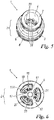
- a filter of the aforesaid type is indicated in a general way by 1, and comprises a body 2.
- This body comprises a tubular element 3 of plastic material which is internally hollow at 4 and has a first end 6 and a second end 7, both of which are open.
- This hollow tubular element has an outer surface of variable cross section, which is wider at a first portion 8 near the first end 6 and narrower in a second portion 9 near the second end 7.
- these portions provide recesses 11 and 12 respectively, capable of accommodating corresponding sealing elements (not shown). In other embodiments of the invention, however, these recesses may not be provided, or may each contain more than one sealing element (O-ring).
- Sealing is provided between said elements or the portions 8 and 9 and corresponding conduit walls (not shown) with which the filter 1 is associated in a known way, such as conduits for supplying a fuel (for example petrol or diesel fuel) to the injectors of an internal combustion engine, or conduits of a braking system in which the filter 1 is used to capture any impurities in the fluid circulating in these conduits.
- a fuel for example petrol or diesel fuel
- conduits of a braking system in which the filter 1 is used to capture any impurities in the fluid circulating in these conduits.
- the first end 6 has a hole 15 partially blocked by arms or spokes 17 running from an edge 18 of this end (or a position near this edge) and connected to a central body 20 positioned along the longitudinal axis W of the filter body 2.
- These arms or spokes 17 are spaced apart at equal intervals (of about 120°, for example, as in the figures in which there are three of these components, or 90° if there are four of them, or 180° if there are two of them) and define partial openings 15A connected to the internal cavity 4 of the tubular element 3 (or of the body 2 of the filter 1).
- the second end 7 has one opening 7A.
- a fluid present in the conduit in which the filter 1 is placed can enter and leave the cavity 4 of the tubular body 2 through the latter opening and through the aforementioned 15° partial openings.
- the filter element 21 is of the type comprising a body 22 which, in the embodiment shown in the figures, has a tapered shape, in particular a frustoconical shape; this body has a flattened end part 23 (orthogonal to the axis W) from which there extends a filter wall 24 positioned so as to widen at the free end 25 (thereby establishing the frustoconical shape of the filter).
- This wall is “pleated”, and therefore comprises a plurality of folds 27 which can increase the filter surface area.
- These folds 27 define between them, when viewed from outside the element 21, recesses 28 alternating with fins 29.
- brackets of substantially triangular shape 30 projecting from a wall 32 of the cavity 4 of the tubular element 3, said brackets 30 each having a tapered free end 34. The folds bear on these ends. The brackets are fixed to the folds 27.
- the tubular element 3 and the filter element 21 are produced by co-moulding, that is to say by a single forming operation carried out completely in an injection mould for plastic material, causing the element 21 to be placed entirely inside the tubular element 3 and fastened thereto.
- co-moulding denotes an injection moulding operation for producing a product (the filter 1) without introducing into the mould any previously shaped element for subsequent fastening to an external body of plastic material.
- this term signifies a moulding operation in which the forming of any component of the end product (in this case, the tubular element 3 and the filter element 21) into the desired shape takes place directly in the mould without the need to introduce a pre-shaped component into the mould.
- the filter element 21 is entirely within the cavity 4 in the first portion 8 of the tubular element, and is protected by this portion from any impact on the filter 1; this filter element 21 is made in one piece with the tubular element 3, with which it is associated at the brackets 30 and at the central body 20 after moulding (which is performed by injection). This filter element 21 is thus completely protected from any impact that may occur during installation in the position of use.
- the tubular element 3 completely surrounds the filter element 21 on all sides and also protects it from any impact that may occur in the direction of the longitudinal axis W and the first end 6, because of the presence at this end of the arms 17 and of the central body 20 positioned next to the flattened part 23 of the body 22 of the filter element 21.
- the filter element 21 is co-moulded with the tubular element 3 and is inside the latter, being laterally protected by the first portion 8 of this element 3, there is still an optimal free surface area for filtering the fluid circulating within the cavity 4, while still allowing it to pass towards the corresponding injector or the braking or transmission members of the respective conduit of the system in which the filter 1 is fitted.
- the filter 1 is truly made in one piece, thereby facilitating its transport and its positioning in the respective conduit. Being co-moulded, its components are made directly by a single moulding operation, and there is no need to suspend this operation in order to introduce the filter element into the mould, which would slow down the industrial production of the filters 1.
- the method for producing the filter 1 by the co-moulding operation is executed by supplying to the mould a mesh portion, which is flat, for example, and is capable of forming the filter element 21, or by creating this mesh portion directly in the mould by injecting material in the fluid state into the mould.
- this mesh portion is folded to the desired shape (for example, a frustoconical shape as shown by way of example in the figures), and this is followed by the injection into the mould of the plastic material for forming the tubular element 3 and its various portions in the shape defined by the mould.
- the co-moulding operation ends with the removal of the finished filter 1 from the mould.
- the shape of the filter element in the tubular element 3 may also be ogival, that is to say still tapered towards one of its ends (which may be either closed or open), or cylindrical and closed at one end by the central body 20 which is associated, as described, with two or more arms 17 (which are preferably, but not necessarily, equally spaced).
- the fluid would be filtered in its passage through the (vertical) wall 24 of this element before passing out of the tubular element 3 through the openings 15A.
- the filter element is intrinsically protected by the tubular element, making it unnecessary to add any other component (apart from the sealing elements in the annular recesses 11 and 12) to the tubular element, whereas this would be necessary in the currently known solutions.
- the tubular element may have a constant cross section and may not have two portions 8 and 9 with different cross sections as in the example of the figures described above; or the filter element 21 may be rotated through 180° from the position described and have its flattened end part facing the second end 7 (instead of the first end 6 as in the figures) of the tubular element 3. Again, this filter element may also be positioned asymmetrically in the element 3. Additionally, the filter may be used with any fluid, whether liquid or gaseous.
Landscapes
- Engineering & Computer Science (AREA)
- Chemical & Material Sciences (AREA)
- Chemical Kinetics & Catalysis (AREA)
- Combustion & Propulsion (AREA)
- Mechanical Engineering (AREA)
- General Engineering & Computer Science (AREA)
- Filtration Of Liquid (AREA)
- Filtering Materials (AREA)
- Lubrication Details And Ventilation Of Internal Combustion Engines (AREA)
- Fuel-Injection Apparatus (AREA)
- Filtering Of Dispersed Particles In Gases (AREA)
- Injection Moulding Of Plastics Or The Like (AREA)
- General Details Of Gearings (AREA)
Priority Applications (1)
| Application Number | Priority Date | Filing Date | Title |
|---|---|---|---|
| PL15788196T PL3198134T3 (pl) | 2014-09-22 | 2015-09-17 | Sposób wytwarzania usprawnionego filtra do wtryskiwaczy paliwa, olejów, roztworów, dodatków i ogółem płynów oraz tak wytwarzany filtr |
Applications Claiming Priority (2)
| Application Number | Priority Date | Filing Date | Title |
|---|---|---|---|
| ITMI20141640 | 2014-09-22 | ||
| PCT/IB2015/057152 WO2016046700A1 (en) | 2014-09-22 | 2015-09-17 | Method for producing an improved filter for injectors of fuel, oils, solutions, additives and fluids in general, and filter thus produced |
Publications (2)
| Publication Number | Publication Date |
|---|---|
| EP3198134A1 EP3198134A1 (en) | 2017-08-02 |
| EP3198134B1 true EP3198134B1 (en) | 2018-12-12 |
Family
ID=51846806
Family Applications (1)
| Application Number | Title | Priority Date | Filing Date |
|---|---|---|---|
| EP15788196.2A Active EP3198134B1 (en) | 2014-09-22 | 2015-09-17 | Method for producing an improved filter for injectors of fuel, oils, solutions, additives and fluids in general, and filter thus produced |
Country Status (9)
| Country | Link |
|---|---|
| US (1) | US10451016B2 (pl) |
| EP (1) | EP3198134B1 (pl) |
| JP (1) | JP6715240B2 (pl) |
| KR (1) | KR102096696B1 (pl) |
| CN (1) | CN106795847B (pl) |
| BR (1) | BR112017005822B1 (pl) |
| PL (1) | PL3198134T3 (pl) |
| TR (1) | TR201901979T4 (pl) |
| WO (1) | WO2016046700A1 (pl) |
Families Citing this family (1)
| Publication number | Priority date | Publication date | Assignee | Title |
|---|---|---|---|---|
| IT201900010917A1 (it) * | 2019-07-04 | 2021-01-04 | Gvs Spa | "dispositivo per intrappolare e rimuovere un liquido presente in un circuito per la ventilazione di un paziente" |
Family Cites Families (16)
| Publication number | Priority date | Publication date | Assignee | Title |
|---|---|---|---|---|
| GB2026602B (en) | 1978-07-31 | 1982-12-01 | Ntn Toyo Bearing Co Ltd | Fuel injection apparatus for internal combustion engines |
| JPS60153910A (ja) | 1984-01-24 | 1985-08-13 | Mizusaku Kk | 濾過装置 |
| DE3718068C1 (en) | 1987-05-29 | 1988-06-30 | Daimler Benz Ag | Rod-shaped gauze filter for installation in the flow path of a fuel supply |
| IT215053Z2 (it) | 1988-12-16 | 1990-07-30 | Weber Srl | Carburatore con dispositivo di tipo perfezionato per l alimentazione di un motore a regime di minimo |
| US5335863A (en) | 1993-05-03 | 1994-08-09 | Siemens Automotive L.P. | Filter cartridge mounting for a top-feed fuel injector |
| IT1296553B1 (it) | 1997-11-14 | 1999-07-09 | Gvs S R L | Filtro per iniettori di carburante e per impianti frenanti dotati di dispositivo antibloccaggio (abs). |
| US6629650B2 (en) * | 2001-07-10 | 2003-10-07 | Delphi Technologies, Inc. | Fuel injector with integral damper |
| JP2005226557A (ja) * | 2004-02-13 | 2005-08-25 | Denso Corp | 燃料噴射弁 |
| JP2005349652A (ja) * | 2004-06-09 | 2005-12-22 | Honda Motor Co Ltd | 樹脂製フィルター及びその製法 |
| JP2007064076A (ja) * | 2005-08-30 | 2007-03-15 | Toyota Motor Corp | 内燃機関の燃料噴射装置 |
| JP2008194587A (ja) * | 2007-02-09 | 2008-08-28 | Toyo Roki Mfg Co Ltd | 濾過フィルタ及びその製造方法 |
| JP5276666B2 (ja) * | 2007-09-05 | 2013-08-28 | ジヴエッセ ソチエタ ぺル アチオーニ | 血液透析ライン用の改良された保護フィルタ |
| WO2013022163A1 (ko) * | 2011-08-10 | 2013-02-14 | Lee Choong-Joong | 벤츄리 노즐과 이를 탑재한 집진장치용 필터 구조체 |
| DE202011104686U1 (de) * | 2011-08-18 | 2011-12-19 | Mahle International Gmbh | Flüssigkeitsfilter, insbesondere ein Ölfilter |
| JP6254794B2 (ja) * | 2013-08-20 | 2017-12-27 | 株式会社エンプラス | メッシュフィルタ |
| CN203790686U (zh) * | 2014-03-10 | 2014-08-27 | 成都威特电喷有限责任公司 | 燃油喷射系统管路防堵过滤器 |
-
2015
- 2015-09-17 BR BR112017005822-7A patent/BR112017005822B1/pt active IP Right Grant
- 2015-09-17 EP EP15788196.2A patent/EP3198134B1/en active Active
- 2015-09-17 US US15/512,553 patent/US10451016B2/en active Active
- 2015-09-17 JP JP2017515739A patent/JP6715240B2/ja active Active
- 2015-09-17 TR TR2019/01979T patent/TR201901979T4/tr unknown
- 2015-09-17 KR KR1020177009963A patent/KR102096696B1/ko active Active
- 2015-09-17 CN CN201580050898.6A patent/CN106795847B/zh active Active
- 2015-09-17 WO PCT/IB2015/057152 patent/WO2016046700A1/en not_active Ceased
- 2015-09-17 PL PL15788196T patent/PL3198134T3/pl unknown
Non-Patent Citations (1)
| Title |
|---|
| None * |
Also Published As
| Publication number | Publication date |
|---|---|
| EP3198134A1 (en) | 2017-08-02 |
| US20170298885A1 (en) | 2017-10-19 |
| WO2016046700A1 (en) | 2016-03-31 |
| TR201901979T4 (tr) | 2019-03-21 |
| BR112017005822B1 (pt) | 2022-08-16 |
| KR102096696B1 (ko) | 2020-05-28 |
| KR20170057337A (ko) | 2017-05-24 |
| JP6715240B2 (ja) | 2020-07-01 |
| JP2017534439A (ja) | 2017-11-24 |
| US10451016B2 (en) | 2019-10-22 |
| BR112017005822A2 (pt) | 2017-12-12 |
| PL3198134T3 (pl) | 2019-05-31 |
| CN106795847B (zh) | 2020-01-03 |
| CN106795847A (zh) | 2017-05-31 |
Similar Documents
| Publication | Publication Date | Title |
|---|---|---|
| US11000789B2 (en) | Filter element locking mechanism for clean service | |
| AU2015380319A1 (en) | Filter assembly including flow cap | |
| CN107743414A (zh) | 用于引导流体通过过滤器的流罩以及方法 | |
| CA2943170C (en) | Filter assembly | |
| EP3198134B1 (en) | Method for producing an improved filter for injectors of fuel, oils, solutions, additives and fluids in general, and filter thus produced | |
| US20150209705A1 (en) | Filter base system and filter assembly | |
| WO2013115969A1 (en) | Filtration system | |
| US20140061137A1 (en) | Endcap Bypass Plug, Endcap Assembly and Filter Assembly | |
| US20010029928A1 (en) | Filter for pressure regulator | |
| JP6486183B2 (ja) | 燃料補給システムおよびその組立方法 | |
| CN223709705U (zh) | 一种过滤柱及燃油喷嘴 | |
| CA3035732C (en) | Filter element locking mechanism for clean service | |
| RU2806743C2 (ru) | Фильтр в сборе с перепускной крышкой | |
| US9925482B2 (en) | Oil filter adaptor and method of forming the same | |
| KR20250097439A (ko) | 배기가스 후처리 장치용 담체 캐닝 방법 및 패키징 방법 |
Legal Events
| Date | Code | Title | Description |
|---|---|---|---|
| STAA | Information on the status of an ep patent application or granted ep patent |
Free format text: STATUS: THE INTERNATIONAL PUBLICATION HAS BEEN MADE |
|
| PUAI | Public reference made under article 153(3) epc to a published international application that has entered the european phase |
Free format text: ORIGINAL CODE: 0009012 |
|
| STAA | Information on the status of an ep patent application or granted ep patent |
Free format text: STATUS: REQUEST FOR EXAMINATION WAS MADE |
|
| 17P | Request for examination filed |
Effective date: 20170403 |
|
| AK | Designated contracting states |
Kind code of ref document: A1 Designated state(s): AL AT BE BG CH CY CZ DE DK EE ES FI FR GB GR HR HU IE IS IT LI LT LU LV MC MK MT NL NO PL PT RO RS SE SI SK SM TR |
|
| AX | Request for extension of the european patent |
Extension state: BA ME |
|
| DAV | Request for validation of the european patent (deleted) | ||
| DAX | Request for extension of the european patent (deleted) | ||
| REG | Reference to a national code |
Ref country code: DE Ref legal event code: R079 Ref document number: 602015021551 Country of ref document: DE Free format text: PREVIOUS MAIN CLASS: F02M0061160000 Ipc: B01D0039160000 |
|
| RIC1 | Information provided on ipc code assigned before grant |
Ipc: B01D 39/16 20060101AFI20180529BHEP Ipc: F02M 61/16 20060101ALI20180529BHEP Ipc: B01D 29/31 20060101ALI20180529BHEP Ipc: B01D 29/11 20060101ALI20180529BHEP |
|
| GRAP | Despatch of communication of intention to grant a patent |
Free format text: ORIGINAL CODE: EPIDOSNIGR1 |
|
| STAA | Information on the status of an ep patent application or granted ep patent |
Free format text: STATUS: GRANT OF PATENT IS INTENDED |
|
| INTG | Intention to grant announced |
Effective date: 20180706 |
|
| RIN1 | Information on inventor provided before grant (corrected) |
Inventor name: SCAGLIARINI, MARCO |
|
| GRAS | Grant fee paid |
Free format text: ORIGINAL CODE: EPIDOSNIGR3 |
|
| GRAA | (expected) grant |
Free format text: ORIGINAL CODE: 0009210 |
|
| STAA | Information on the status of an ep patent application or granted ep patent |
Free format text: STATUS: THE PATENT HAS BEEN GRANTED |
|
| AK | Designated contracting states |
Kind code of ref document: B1 Designated state(s): AL AT BE BG CH CY CZ DE DK EE ES FI FR GB GR HR HU IE IS IT LI LT LU LV MC MK MT NL NO PL PT RO RS SE SI SK SM TR |
|
| REG | Reference to a national code |
Ref country code: GB Ref legal event code: FG4D |
|
| REG | Reference to a national code |
Ref country code: CH Ref legal event code: EP |
|
| REG | Reference to a national code |
Ref country code: AT Ref legal event code: REF Ref document number: 1075208 Country of ref document: AT Kind code of ref document: T Effective date: 20181215 |
|
| REG | Reference to a national code |
Ref country code: DE Ref legal event code: R096 Ref document number: 602015021551 Country of ref document: DE |
|
| REG | Reference to a national code |
Ref country code: IE Ref legal event code: FG4D |
|
| REG | Reference to a national code |
Ref country code: CH Ref legal event code: NV Representative=s name: R.A. EGLI AND CO, PATENTANWAELTE, CH |
|
| REG | Reference to a national code |
Ref country code: RO Ref legal event code: EPE |
|
| REG | Reference to a national code |
Ref country code: NL Ref legal event code: MP Effective date: 20181212 |
|
| REG | Reference to a national code |
Ref country code: LT Ref legal event code: MG4D |
|
| PG25 | Lapsed in a contracting state [announced via postgrant information from national office to epo] |
Ref country code: LT Free format text: LAPSE BECAUSE OF FAILURE TO SUBMIT A TRANSLATION OF THE DESCRIPTION OR TO PAY THE FEE WITHIN THE PRESCRIBED TIME-LIMIT Effective date: 20181212 Ref country code: NO Free format text: LAPSE BECAUSE OF FAILURE TO SUBMIT A TRANSLATION OF THE DESCRIPTION OR TO PAY THE FEE WITHIN THE PRESCRIBED TIME-LIMIT Effective date: 20190312 Ref country code: BG Free format text: LAPSE BECAUSE OF FAILURE TO SUBMIT A TRANSLATION OF THE DESCRIPTION OR TO PAY THE FEE WITHIN THE PRESCRIBED TIME-LIMIT Effective date: 20190312 Ref country code: ES Free format text: LAPSE BECAUSE OF FAILURE TO SUBMIT A TRANSLATION OF THE DESCRIPTION OR TO PAY THE FEE WITHIN THE PRESCRIBED TIME-LIMIT Effective date: 20181212 Ref country code: LV Free format text: LAPSE BECAUSE OF FAILURE TO SUBMIT A TRANSLATION OF THE DESCRIPTION OR TO PAY THE FEE WITHIN THE PRESCRIBED TIME-LIMIT Effective date: 20181212 Ref country code: HR Free format text: LAPSE BECAUSE OF FAILURE TO SUBMIT A TRANSLATION OF THE DESCRIPTION OR TO PAY THE FEE WITHIN THE PRESCRIBED TIME-LIMIT Effective date: 20181212 Ref country code: FI Free format text: LAPSE BECAUSE OF FAILURE TO SUBMIT A TRANSLATION OF THE DESCRIPTION OR TO PAY THE FEE WITHIN THE PRESCRIBED TIME-LIMIT Effective date: 20181212 |
|
| REG | Reference to a national code |
Ref country code: AT Ref legal event code: MK05 Ref document number: 1075208 Country of ref document: AT Kind code of ref document: T Effective date: 20181212 |
|
| PG25 | Lapsed in a contracting state [announced via postgrant information from national office to epo] |
Ref country code: SE Free format text: LAPSE BECAUSE OF FAILURE TO SUBMIT A TRANSLATION OF THE DESCRIPTION OR TO PAY THE FEE WITHIN THE PRESCRIBED TIME-LIMIT Effective date: 20181212 Ref country code: AL Free format text: LAPSE BECAUSE OF FAILURE TO SUBMIT A TRANSLATION OF THE DESCRIPTION OR TO PAY THE FEE WITHIN THE PRESCRIBED TIME-LIMIT Effective date: 20181212 Ref country code: GR Free format text: LAPSE BECAUSE OF FAILURE TO SUBMIT A TRANSLATION OF THE DESCRIPTION OR TO PAY THE FEE WITHIN THE PRESCRIBED TIME-LIMIT Effective date: 20190313 Ref country code: RS Free format text: LAPSE BECAUSE OF FAILURE TO SUBMIT A TRANSLATION OF THE DESCRIPTION OR TO PAY THE FEE WITHIN THE PRESCRIBED TIME-LIMIT Effective date: 20181212 |
|
| PG25 | Lapsed in a contracting state [announced via postgrant information from national office to epo] |
Ref country code: NL Free format text: LAPSE BECAUSE OF FAILURE TO SUBMIT A TRANSLATION OF THE DESCRIPTION OR TO PAY THE FEE WITHIN THE PRESCRIBED TIME-LIMIT Effective date: 20181212 |
|
| PG25 | Lapsed in a contracting state [announced via postgrant information from national office to epo] |
Ref country code: IT Free format text: LAPSE BECAUSE OF FAILURE TO SUBMIT A TRANSLATION OF THE DESCRIPTION OR TO PAY THE FEE WITHIN THE PRESCRIBED TIME-LIMIT Effective date: 20181212 Ref country code: PT Free format text: LAPSE BECAUSE OF FAILURE TO SUBMIT A TRANSLATION OF THE DESCRIPTION OR TO PAY THE FEE WITHIN THE PRESCRIBED TIME-LIMIT Effective date: 20190412 |
|
| PG25 | Lapsed in a contracting state [announced via postgrant information from national office to epo] |
Ref country code: EE Free format text: LAPSE BECAUSE OF FAILURE TO SUBMIT A TRANSLATION OF THE DESCRIPTION OR TO PAY THE FEE WITHIN THE PRESCRIBED TIME-LIMIT Effective date: 20181212 Ref country code: IS Free format text: LAPSE BECAUSE OF FAILURE TO SUBMIT A TRANSLATION OF THE DESCRIPTION OR TO PAY THE FEE WITHIN THE PRESCRIBED TIME-LIMIT Effective date: 20190412 Ref country code: SK Free format text: LAPSE BECAUSE OF FAILURE TO SUBMIT A TRANSLATION OF THE DESCRIPTION OR TO PAY THE FEE WITHIN THE PRESCRIBED TIME-LIMIT Effective date: 20181212 Ref country code: SM Free format text: LAPSE BECAUSE OF FAILURE TO SUBMIT A TRANSLATION OF THE DESCRIPTION OR TO PAY THE FEE WITHIN THE PRESCRIBED TIME-LIMIT Effective date: 20181212 |
|
| REG | Reference to a national code |
Ref country code: DE Ref legal event code: R097 Ref document number: 602015021551 Country of ref document: DE |
|
| PLBE | No opposition filed within time limit |
Free format text: ORIGINAL CODE: 0009261 |
|
| STAA | Information on the status of an ep patent application or granted ep patent |
Free format text: STATUS: NO OPPOSITION FILED WITHIN TIME LIMIT |
|
| PG25 | Lapsed in a contracting state [announced via postgrant information from national office to epo] |
Ref country code: DK Free format text: LAPSE BECAUSE OF FAILURE TO SUBMIT A TRANSLATION OF THE DESCRIPTION OR TO PAY THE FEE WITHIN THE PRESCRIBED TIME-LIMIT Effective date: 20181212 Ref country code: AT Free format text: LAPSE BECAUSE OF FAILURE TO SUBMIT A TRANSLATION OF THE DESCRIPTION OR TO PAY THE FEE WITHIN THE PRESCRIBED TIME-LIMIT Effective date: 20181212 Ref country code: SI Free format text: LAPSE BECAUSE OF FAILURE TO SUBMIT A TRANSLATION OF THE DESCRIPTION OR TO PAY THE FEE WITHIN THE PRESCRIBED TIME-LIMIT Effective date: 20181212 |
|
| 26N | No opposition filed |
Effective date: 20190913 |
|
| PG25 | Lapsed in a contracting state [announced via postgrant information from national office to epo] |
Ref country code: MC Free format text: LAPSE BECAUSE OF FAILURE TO SUBMIT A TRANSLATION OF THE DESCRIPTION OR TO PAY THE FEE WITHIN THE PRESCRIBED TIME-LIMIT Effective date: 20181212 |
|
| PG25 | Lapsed in a contracting state [announced via postgrant information from national office to epo] |
Ref country code: LU Free format text: LAPSE BECAUSE OF NON-PAYMENT OF DUE FEES Effective date: 20190917 |
|
| REG | Reference to a national code |
Ref country code: BE Ref legal event code: MM Effective date: 20190930 |
|
| PG25 | Lapsed in a contracting state [announced via postgrant information from national office to epo] |
Ref country code: BE Free format text: LAPSE BECAUSE OF NON-PAYMENT OF DUE FEES Effective date: 20190930 |
|
| PG25 | Lapsed in a contracting state [announced via postgrant information from national office to epo] |
Ref country code: CY Free format text: LAPSE BECAUSE OF FAILURE TO SUBMIT A TRANSLATION OF THE DESCRIPTION OR TO PAY THE FEE WITHIN THE PRESCRIBED TIME-LIMIT Effective date: 20181212 |
|
| PG25 | Lapsed in a contracting state [announced via postgrant information from national office to epo] |
Ref country code: HU Free format text: LAPSE BECAUSE OF FAILURE TO SUBMIT A TRANSLATION OF THE DESCRIPTION OR TO PAY THE FEE WITHIN THE PRESCRIBED TIME-LIMIT; INVALID AB INITIO Effective date: 20150917 Ref country code: MT Free format text: LAPSE BECAUSE OF FAILURE TO SUBMIT A TRANSLATION OF THE DESCRIPTION OR TO PAY THE FEE WITHIN THE PRESCRIBED TIME-LIMIT Effective date: 20181212 |
|
| PG25 | Lapsed in a contracting state [announced via postgrant information from national office to epo] |
Ref country code: MK Free format text: LAPSE BECAUSE OF FAILURE TO SUBMIT A TRANSLATION OF THE DESCRIPTION OR TO PAY THE FEE WITHIN THE PRESCRIBED TIME-LIMIT Effective date: 20181212 |
|
| P01 | Opt-out of the competence of the unified patent court (upc) registered |
Effective date: 20230602 |
|
| REG | Reference to a national code |
Ref country code: CH Ref legal event code: U11 Free format text: ST27 STATUS EVENT CODE: U-0-0-U10-U11 (AS PROVIDED BY THE NATIONAL OFFICE) Effective date: 20251001 |
|
| PGFP | Annual fee paid to national office [announced via postgrant information from national office to epo] |
Ref country code: DE Payment date: 20250929 Year of fee payment: 11 |
|
| PGFP | Annual fee paid to national office [announced via postgrant information from national office to epo] |
Ref country code: PL Payment date: 20250908 Year of fee payment: 11 Ref country code: TR Payment date: 20250908 Year of fee payment: 11 |
|
| PGFP | Annual fee paid to national office [announced via postgrant information from national office to epo] |
Ref country code: GB Payment date: 20250929 Year of fee payment: 11 |
|
| PGFP | Annual fee paid to national office [announced via postgrant information from national office to epo] |
Ref country code: FR Payment date: 20250925 Year of fee payment: 11 |
|
| PGFP | Annual fee paid to national office [announced via postgrant information from national office to epo] |
Ref country code: IE Payment date: 20250929 Year of fee payment: 11 Ref country code: CZ Payment date: 20250908 Year of fee payment: 11 |
|
| PGFP | Annual fee paid to national office [announced via postgrant information from national office to epo] |
Ref country code: RO Payment date: 20250909 Year of fee payment: 11 |
|
| PGFP | Annual fee paid to national office [announced via postgrant information from national office to epo] |
Ref country code: CH Payment date: 20251001 Year of fee payment: 11 |