EP3196992A1 - Fiber laser device and manufacturing method for amplification coil - Google Patents
Fiber laser device and manufacturing method for amplification coil Download PDFInfo
- Publication number
- EP3196992A1 EP3196992A1 EP16749091.1A EP16749091A EP3196992A1 EP 3196992 A1 EP3196992 A1 EP 3196992A1 EP 16749091 A EP16749091 A EP 16749091A EP 3196992 A1 EP3196992 A1 EP 3196992A1
- Authority
- EP
- European Patent Office
- Prior art keywords
- amplifying
- optical fiber
- coil
- amplifying optical
- fiber
- Prior art date
- Legal status (The legal status is an assumption and is not a legal conclusion. Google has not performed a legal analysis and makes no representation as to the accuracy of the status listed.)
- Withdrawn
Links
Images




Classifications
-
- H—ELECTRICITY
- H01—ELECTRIC ELEMENTS
- H01S—DEVICES USING THE PROCESS OF LIGHT AMPLIFICATION BY STIMULATED EMISSION OF RADIATION [LASER] TO AMPLIFY OR GENERATE LIGHT; DEVICES USING STIMULATED EMISSION OF ELECTROMAGNETIC RADIATION IN WAVE RANGES OTHER THAN OPTICAL
- H01S3/00—Lasers, i.e. devices using stimulated emission of electromagnetic radiation in the infrared, visible or ultraviolet wave range
- H01S3/05—Construction or shape of optical resonators; Accommodation of active medium therein; Shape of active medium
- H01S3/06—Construction or shape of active medium
- H01S3/063—Waveguide lasers, i.e. whereby the dimensions of the waveguide are of the order of the light wavelength
- H01S3/067—Fibre lasers
- H01S3/06708—Constructional details of the fibre, e.g. compositions, cross-section, shape or tapering
- H01S3/06729—Peculiar transverse fibre profile
-
- G—PHYSICS
- G02—OPTICS
- G02B—OPTICAL ELEMENTS, SYSTEMS OR APPARATUS
- G02B6/00—Light guides; Structural details of arrangements comprising light guides and other optical elements, e.g. couplings
- G02B6/02—Optical fibres with cladding with or without a coating
-
- H—ELECTRICITY
- H01—ELECTRIC ELEMENTS
- H01S—DEVICES USING THE PROCESS OF LIGHT AMPLIFICATION BY STIMULATED EMISSION OF RADIATION [LASER] TO AMPLIFY OR GENERATE LIGHT; DEVICES USING STIMULATED EMISSION OF ELECTROMAGNETIC RADIATION IN WAVE RANGES OTHER THAN OPTICAL
- H01S3/00—Lasers, i.e. devices using stimulated emission of electromagnetic radiation in the infrared, visible or ultraviolet wave range
- H01S3/02—Constructional details
- H01S3/04—Arrangements for thermal management
-
- H—ELECTRICITY
- H01—ELECTRIC ELEMENTS
- H01S—DEVICES USING THE PROCESS OF LIGHT AMPLIFICATION BY STIMULATED EMISSION OF RADIATION [LASER] TO AMPLIFY OR GENERATE LIGHT; DEVICES USING STIMULATED EMISSION OF ELECTROMAGNETIC RADIATION IN WAVE RANGES OTHER THAN OPTICAL
- H01S3/00—Lasers, i.e. devices using stimulated emission of electromagnetic radiation in the infrared, visible or ultraviolet wave range
- H01S3/02—Constructional details
- H01S3/04—Arrangements for thermal management
- H01S3/042—Arrangements for thermal management for solid state lasers
-
- H—ELECTRICITY
- H01—ELECTRIC ELEMENTS
- H01S—DEVICES USING THE PROCESS OF LIGHT AMPLIFICATION BY STIMULATED EMISSION OF RADIATION [LASER] TO AMPLIFY OR GENERATE LIGHT; DEVICES USING STIMULATED EMISSION OF ELECTROMAGNETIC RADIATION IN WAVE RANGES OTHER THAN OPTICAL
- H01S3/00—Lasers, i.e. devices using stimulated emission of electromagnetic radiation in the infrared, visible or ultraviolet wave range
- H01S3/05—Construction or shape of optical resonators; Accommodation of active medium therein; Shape of active medium
- H01S3/06—Construction or shape of active medium
- H01S3/063—Waveguide lasers, i.e. whereby the dimensions of the waveguide are of the order of the light wavelength
- H01S3/067—Fibre lasers
- H01S3/06704—Housings; Packages
-
- H—ELECTRICITY
- H01—ELECTRIC ELEMENTS
- H01S—DEVICES USING THE PROCESS OF LIGHT AMPLIFICATION BY STIMULATED EMISSION OF RADIATION [LASER] TO AMPLIFY OR GENERATE LIGHT; DEVICES USING STIMULATED EMISSION OF ELECTROMAGNETIC RADIATION IN WAVE RANGES OTHER THAN OPTICAL
- H01S3/00—Lasers, i.e. devices using stimulated emission of electromagnetic radiation in the infrared, visible or ultraviolet wave range
- H01S3/05—Construction or shape of optical resonators; Accommodation of active medium therein; Shape of active medium
- H01S3/06—Construction or shape of active medium
- H01S3/063—Waveguide lasers, i.e. whereby the dimensions of the waveguide are of the order of the light wavelength
- H01S3/067—Fibre lasers
- H01S3/06708—Constructional details of the fibre, e.g. compositions, cross-section, shape or tapering
- H01S3/06729—Peculiar transverse fibre profile
- H01S3/06733—Fibre having more than one cladding
-
- H—ELECTRICITY
- H01—ELECTRIC ELEMENTS
- H01S—DEVICES USING THE PROCESS OF LIGHT AMPLIFICATION BY STIMULATED EMISSION OF RADIATION [LASER] TO AMPLIFY OR GENERATE LIGHT; DEVICES USING STIMULATED EMISSION OF ELECTROMAGNETIC RADIATION IN WAVE RANGES OTHER THAN OPTICAL
- H01S3/00—Lasers, i.e. devices using stimulated emission of electromagnetic radiation in the infrared, visible or ultraviolet wave range
- H01S3/09—Processes or apparatus for excitation, e.g. pumping
- H01S3/091—Processes or apparatus for excitation, e.g. pumping using optical pumping
- H01S3/094—Processes or apparatus for excitation, e.g. pumping using optical pumping by coherent light
- H01S3/094003—Processes or apparatus for excitation, e.g. pumping using optical pumping by coherent light the pumped medium being a fibre
-
- G—PHYSICS
- G02—OPTICS
- G02B—OPTICAL ELEMENTS, SYSTEMS OR APPARATUS
- G02B6/00—Light guides; Structural details of arrangements comprising light guides and other optical elements, e.g. couplings
- G02B6/44—Mechanical structures for providing tensile strength and external protection for fibres, e.g. optical transmission cables
- G02B6/4439—Auxiliary devices
- G02B6/4457—Bobbins; Reels
-
- G—PHYSICS
- G02—OPTICS
- G02B—OPTICAL ELEMENTS, SYSTEMS OR APPARATUS
- G02B6/00—Light guides; Structural details of arrangements comprising light guides and other optical elements, e.g. couplings
- G02B6/44—Mechanical structures for providing tensile strength and external protection for fibres, e.g. optical transmission cables
- G02B6/4479—Manufacturing methods of optical cables
- G02B6/449—Twisting
-
- H—ELECTRICITY
- H01—ELECTRIC ELEMENTS
- H01S—DEVICES USING THE PROCESS OF LIGHT AMPLIFICATION BY STIMULATED EMISSION OF RADIATION [LASER] TO AMPLIFY OR GENERATE LIGHT; DEVICES USING STIMULATED EMISSION OF ELECTROMAGNETIC RADIATION IN WAVE RANGES OTHER THAN OPTICAL
- H01S3/00—Lasers, i.e. devices using stimulated emission of electromagnetic radiation in the infrared, visible or ultraviolet wave range
- H01S3/05—Construction or shape of optical resonators; Accommodation of active medium therein; Shape of active medium
- H01S3/06—Construction or shape of active medium
- H01S3/063—Waveguide lasers, i.e. whereby the dimensions of the waveguide are of the order of the light wavelength
- H01S3/067—Fibre lasers
- H01S3/0675—Resonators including a grating structure, e.g. distributed Bragg reflectors [DBR] or distributed feedback [DFB] fibre lasers
-
- H—ELECTRICITY
- H01—ELECTRIC ELEMENTS
- H01S—DEVICES USING THE PROCESS OF LIGHT AMPLIFICATION BY STIMULATED EMISSION OF RADIATION [LASER] TO AMPLIFY OR GENERATE LIGHT; DEVICES USING STIMULATED EMISSION OF ELECTROMAGNETIC RADIATION IN WAVE RANGES OTHER THAN OPTICAL
- H01S3/00—Lasers, i.e. devices using stimulated emission of electromagnetic radiation in the infrared, visible or ultraviolet wave range
- H01S3/09—Processes or apparatus for excitation, e.g. pumping
- H01S3/091—Processes or apparatus for excitation, e.g. pumping using optical pumping
- H01S3/094—Processes or apparatus for excitation, e.g. pumping using optical pumping by coherent light
- H01S3/094003—Processes or apparatus for excitation, e.g. pumping using optical pumping by coherent light the pumped medium being a fibre
- H01S3/094007—Cladding pumping, i.e. pump light propagating in a clad surrounding the active core
-
- H—ELECTRICITY
- H01—ELECTRIC ELEMENTS
- H01S—DEVICES USING THE PROCESS OF LIGHT AMPLIFICATION BY STIMULATED EMISSION OF RADIATION [LASER] TO AMPLIFY OR GENERATE LIGHT; DEVICES USING STIMULATED EMISSION OF ELECTROMAGNETIC RADIATION IN WAVE RANGES OTHER THAN OPTICAL
- H01S3/00—Lasers, i.e. devices using stimulated emission of electromagnetic radiation in the infrared, visible or ultraviolet wave range
- H01S3/09—Processes or apparatus for excitation, e.g. pumping
- H01S3/091—Processes or apparatus for excitation, e.g. pumping using optical pumping
- H01S3/094—Processes or apparatus for excitation, e.g. pumping using optical pumping by coherent light
- H01S3/0941—Processes or apparatus for excitation, e.g. pumping using optical pumping by coherent light of a laser diode
- H01S3/09415—Processes or apparatus for excitation, e.g. pumping using optical pumping by coherent light of a laser diode the pumping beam being parallel to the lasing mode of the pumped medium, e.g. end-pumping
Definitions
- the present invention relates to a fiber laser apparatus and a method of manufacturing an amplifying coil.
- a cross-sectional shape of the first cladding has a shape having rotational symmetry such as a regular hexagon shape
- light propagating in the first cladding spirally travels while being entirely reflected at a constant angle at an interface between the first cladding and the second cladding.
- pumping light which is once deviated from a core travels in the first cladding without changing the incident angle (reflection angle) with respect to the interface. Therefore, this pumping light does not reach the core no matter how many times it is reflected. Accordingly, the light substantially contributing as the pumping light is only a portion of the light that is launched into the amplifying optical fiber, and there is a problem that utilization efficiency of the pumping light is low.
- Patent Document 1 discloses an optical amplifier in which a first cladding has two or more linear reflecting surfaces, and which includes a double clad fiber in which directions of the reflecting surfaces with respect to a core are different from each other at an arbitrary location in a light propagation direction.
- Patent Document 1 Japanese Unexamined Patent Application, First Publication No. 2001-13346
- Patent Document 1 discloses that the double clad fiber may be fixed to a system in a twisted state.
- a trouble such as dispersion of the wound optical fiber may occur. Therefore, there is a problem that handling with the coil alone is difficult.
- An aspect of the invention is to solve the problems, and an object thereof is to provide a fiber laser apparatus having an amplifying coil which can sufficiently maintain a twisted state of an optical fiber and can be easily handled.
- an object of another aspect of the invention is to provide a method of easily manufacturing an amplifying coil which can sufficiently maintain a twisted state of an optical fiber and can be easily handled.
- a fiber laser apparatus includes: a pumping light source which launches pumping light; an amplifying optical fiber which includes a core and a noncircular cladding, and absorbs the pumping light to launch laser light; an amplifying coil which has a configuration around which the amplifying optical fiber is wound; a first reflector which is provided on an input side of the amplifying coil and is configured to reflect the laser light toward the amplifying coil; and a second reflector which is provided on a launching side of the amplifying coil, has a lower reflectance than a reflectance of the first reflector, and is configured to reflect the laser light toward the amplifying coil.
- the amplifying optical fiber is wound with a center axis of the amplifying optical fiber as a center in a state of being twisted in a peripheral direction of the amplifying optical fiber, and the wound amplifying optical fiber is fixed and integrated.
- the amplifying optical fiber is wound with the center axis of the amplifying optical fiber as a center in the state of being twisted in the peripheral direction and the wound amplifying optical fiber is fixed and integrated with each other, it is possible to sufficiently maintain the twisted state of the fiber. Accordingly, it is possible to increase utilization efficiency of the pumping light and to increase an output light amount. In addition, handling with the amplifying coil alone becomes easy.
- a portion between adjacent amplifying optical fibers may be filled with a resin.
- the fiber laser apparatus may further include a cooling member which cools the amplifying coil.
- a twist amount of the amplifying optical fiber may gradually increase in a direction from the first reflector side toward the second reflector side.
- the "twist amount of the amplifying optical fiber” defines as a "number of turns of the amplifying optical fiber per unit length of the amplifying optical fiber”.
- the pumping light is mainly absorbed by the core on an input side (first reflector side), and a skew light component gradually increases in a direction toward a launching side (the second reflector side). Therefore, according to the configuration, since the twist amount of the amplifying optical fiber gradually increases in the direction from the first reflector side toward the second reflector side, the skew light component is easily absorbed by the core on the launching side. Accordingly, it is possible to prevent the deterioration of beam quality of the amplifying optical fiber while decreasing local heat generation and to increase the utilization efficiency of the pumping light.
- the twist amount of the amplifying optical fiber may be 3 turns/m or less.
- a method of manufacturing an amplifying coil includes: winding an amplifying optical fiber in a coil shape while lowering a portion of the amplifying optical fiber onto one surface of a base; and filling a portion between adjacent amplifying optical fibers with a resin to fix the amplifying optical fibers to each other.
- the amplifying optical fiber is wound in a coil shape while a portion of the amplifying optical fiber is lowered onto the base, the amplifying optical fiber is naturally twisted. Thereafter, the wound amplifying optical fibers are fixed to each other by resin and are integrated. Accordingly, it is possible to easily manufacture the amplifying coil.
- a method of manufacturing an amplifying coil includes: winding the amplifying optical fiber drawn out from a bobbin around a rotary jig to wind the amplifying optical fiber in a coil shape; and filling a portion between adjacent amplifying optical fibers with a resin to fix the amplifying optical fibers to each other.
- a rotation axis of the bobbin and a rotation axis of the rotary jig are disposed to be non-parallel to each other.
- the amplifying optical fiber drawn out from the bobbin is wound around the rotary jig in a state where the rotation axis of the bobbin and the rotation axis of the rotary jig are disposed to be non-parallel to each other, the amplifying optical fiber is twisted. Thereafter, the wound amplifying optical fibers are fixed to each other by the resin and are integrated. Accordingly, it is possible to easily manufacture the amplifying coil.
- the fiber laser apparatus having the amplifying coil which can sufficiently maintain the twisted state of the amplifying optical fiber and can be easily handled.
- FIGS. 1 to 7 a fiber laser apparatus according to a first embodiment of the invention will be described with reference to FIGS. 1 to 7 .
- the fiber laser apparatus includes an amplifying coil having a configuration in which an amplifying optical fiber including a core and a polygonal cladding is wound.
- the fiber laser apparatus according to the embodiment may be used for applications such as laser processing.
- the application is not limited to the laser processing.
- FIG. 1 is a schematic configuration view showing the fiber laser apparatus of the embodiment.
- a fiber laser apparatus 1 includes a pumping light source 2, an optical combiner 3, an optical resonator 4, an input side optical fiber 5, and a launching side optical fiber 6.
- the optical resonator 4 includes an amplifying coil 21 configured of an amplifying optical fiber 25, a first reflector 22, and a second reflector 23.
- An input side optical fiber 5 is connected to one end of the amplifying optical fiber 25, and a launching side optical fiber 6 is connected to the other end of the amplifying optical fiber 25.
- the first reflector 22 is provided in the input side optical fiber 5 and the second reflector 23 is provided in the launching side optical fiber 6.
- the pumping light source 2 is configured of a plurality of laser diodes 11 and launches pumping light.
- a Fabry-Perot type semiconductor laser formed of a GaAs-based semiconductor material is used as each of the laser diodes 11.
- the laser diodes 11 are connected to optical fibers 12, and the pumping light launched from the laser diodes 11 is propagated through the optical fibers 12 as multimode light, for example.
- the optical combiner 3 combines a plurality of pumping lights launched from the plurality of laser diodes 11 to generate one pumping light.
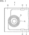
- FIG. 2 is a plan view showing the optical resonator 4 configuring the fiber laser apparatus 1.
- the optical resonator 4 includes the amplifying coil 21, the first reflector 22, the second reflector 23, and a water cooling plate 24.
- the amplifying coil 21 has a configuration in which the amplifying optical fiber 25 is wound.
- the amplifying optical fiber 25 of the embodiment includes a core which propagates the laser light and a noncircular cladding which propagates the pumping light, and is configured of a double clad fiber having two claddings.
- the first reflector 22 is provided in a portion of the input side optical fiber 5 connected to the amplifying coil 21.
- the input side optical fiber 5 is connected to the outer end of the amplifying coil 21.
- the first reflector 22 reflects the laser light which is propagated through the amplifying optical fiber 25.
- the second reflector 23 is provided in a portion of the launching side optical fiber 6 connected to the amplifying coil 21.
- the launching side optical fiber 6 is connected to the inner end of the amplifying coil 21.
- the second reflector 23 reflects part of the laser light which is propagated through the amplifying optical fiber 25.
- the laser light resonates between the first reflector 22 and the second reflector 23 and is amplified.
- Each of the first reflector 22 and the second reflector 23 is configured of a fiber Bragg grating (FBG).
- the FBG is a reflector which forms a portion (grating) in which a refractive index is periodically changed in a longitudinal direction (light propagation direction) of the core. Accordingly, the FBG reflects only light having a specific wavelength corresponding to a period of the grating.
- a reflectance of the second reflector 23 is lower than a reflectance of the first reflector 22.
- the reflectance of the first reflector 22 is 90% or more, and more preferably, is 99% or more.
- the reflectance of the second reflector 23 is 5 to 50%, and more preferably, is 5 to 10%.
- the water cooling plate 24 has a flow path (not shown in figure) that allows cooling water to flow therethrough, and the cooling water is introduced into the flow path so that the water cooling plate 24 is cooled.
- the amplifying coil 21, the first reflector 22 and the second reflector 23 are mounted so as to be in contact with the surface of the water cooling plate 24, and are cooled by the water cooling plate 24.
- parts such as the laser diode 11 (not shown in FIG. 2 ) are mounted on the water cooling plate 24, and the parts are also cooled by the water cooling plate 24.
- the water cooling plate 24 of the embodiment may also be referred to as a cooling member.
- the pumping light launched from the pumping light source 2 enters the amplifying optical fiber 25 via the input side optical fiber 5 and is absorbed by the core of the amplifying optical fiber 25. Accordingly, laser light is outputted from the core of the amplifying optical fiber 25, and the laser light resonates between the first reflector 22 and the second reflector 23 including the amplifying coil 21 so as to be amplified.
- the laser light amplified by the amplifying coil 21 is launched through the launching side optical fiber 6.
- FIG. 3 is a cross-sectional view showing the amplifying coil 21 configuring the optical resonator 13.
- the amplifying coil 21 has a configuration in which the amplifying optical fiber 25 is wound in a plane shape. That is, the amplifying coil 21 is configured of the amplifying optical fiber 25 having one layer. A plurality of amplifying optical fibers 25 are not stacked in a direction perpendicular to a radial direction of the amplifying coil 21. Accordingly, the amplifying optical fiber 25 configuring the amplifying coil 21 is in contact with the water cooling plate 24 over the entire length in the longitudinal direction.
- a portion between adjacent amplifying optical fibers 25 is filled with a resin 26.
- a resin 26 For example, as the resin, an ultraviolet curing type resin, a silicone rubber type resin, or the like is used. Since the portion between the adjacent amplifying optical fibers 25 is filled with the resin 26, the wound amplifying optical fibers 25 are fixed to and integrated with each other. In this way, the integrated amplifying optical fiber 25 configures the amplifying coil 21. As shown in FIG. 2 , when the amplifying coil 21 is viewed in a plan view, the resin 26 is provided over the entire periphery of the amplifying coil 21.
- FIG. 4 is a cross-sectional view showing the amplifying optical fiber 25 configuring the amplifying coil 21.
- the amplifying optical fiber 25 is configured of a double clad fiber having a core 28, a first cladding 29 which covers the outside of the core 28, and a second cladding 30 which covers the outside of the first cladding 29.
- the first cladding 29 is a polygonal cladding (noncircular cladding) having a regular heptagonal cross-sectional shape perpendicular to the center axis of the amplifying optical fiber 25.
- the first cladding 29 is provided concentrically on the outside of the core 28 to which a rare earth element is added, and the second cladding 30 having a regular heptagonal cross-sectional shape is provided outside the first cladding 29.
- a protective coating (not shown in figure) may be provided outside the second cladding 30.
- a rare earth element is added to the core 28 in addition to dopants which increase the refractive index.
- a rare earth element may be added to the entire core 28, and a rare earth element may be added to a portion of the core 28.
- a rare earth element may be added to a portion of the first cladding 29 in addition to the core 28.
- the core 28 and the first cladding 29 configures a waveguide structure.
- the oscillated laser light is guided by the waveguide structure.
- the dopant which increase the refractive index there is Ge, Al, P, or the like.
- co-addition of these elements or co-addition of these elements with F, B, or the like may be performed.
- the rare earth element added to the core 28 is determined according to a pumping wavelength, an amplification wavelength, and an oscillation wavelength.
- Yb is used to obtain light having a wavelength of 1060 nm used in material processing.
- Tm, Bi, Cr, Ce, Nd, Eu, or the like may be added.
- not only a single rare earth element but also a plurality of rare earth elements may be co-added.
- Ge, Al, P, F, B, or the like, and co-addition of these are common as a dopant for controlling the refractive index.
- Ti, Bi, Cl, or the like may be used as the dopant for controlling the refractive index.
- a dispersant for rare earth elements may also be added at the same time.
- Cr, Ga, In, As, Sb, or the like may be used as the dispersant.
- a refractive index profile of the core 28 is referred to as a step type profile having a constant refractive index.
- various refractive index profiles such as a dual shape type profile, a segment core type profile, or a ring type profile may be adopted according to the requirement for optical characteristics of the core 28 determined by the refractive index profile of the core 28.
- the fiber is exemplified in which the core 28, the first cladding 29, and the second cladding 30 are formed of a silica glass-based material.
- the invention is not limited to this.
- an outline of the first cladding 29, that is, a shape of a boundary between the first cladding 29 and the second cladding 30 in the amplifying optical fiber 25 of the embodiment is a regular heptagon which is not twice symmetrical about the axis, light which is not guided by the cladding, does not reach the core, and does not contribute as pumping light, that is, so-called skew light can be suppressed.
- the cross-sectional shape of the first cladding 29 is formed into a polygon, the skew light still remains, and there is a concern that the utilization efficiency of the pumping light cannot be further improved.
- the amplifying optical fiber 25 is wound so as to be twisted in the peripheral direction with the center axis of the amplifying optical fiber 25 as a center.
- a twist amount of the amplifying optical fiber 25 may be constant over the entire length of the amplifying coil 21.
- the twist amount of the amplifying optical fiber 25 may gradually increase in the direction from the first reflector 22 side toward the second reflector 23 side.
- the twist amount of the amplifying optical fiber 25 is 3 turns/m or less.
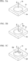
- a base 32 having a circular recessed portion 32h on one surface is prepared.
- the amplifying optical fiber 25 is supported by an arbitrary jig or device (not shown in figure), and one end of the amplifying optical fiber 25 is positioned above the recessed portion 32h of the base 32. In this state, one end of the amplifying optical fiber 25 is lowered onto a bottom surface of the recessed portion 32h. Thereafter, the position of the amplifying optical fiber 25 supported by a jig or the like is always set so as to be positioned above approximately the center of the recessed portion 32h in the vertical direction.
- the amplifying optical fiber 25 is further lowered, as shown in FIG. 5B , after a distal end 25s of the amplifying optical fiber 25 comes into contact with the bottom surface of the recessed portion 32h, the amplifying optical fiber 25 moves to the outside of the recessed portion 32h.
- the amplifying optical fiber 25 is further lowered, as shown in FIG. 5C , the distal end 25s of the amplifying optical fiber 25 moves along a side wall of the recessed portion 32h, and the amplifying optical fiber 25 is circularly wound.
- the winding of the amplifying optical fiber 25 enters from a first turn to a second turn.
- the distal end 25 of the amplifying optical fiber 25 collides with the amplifying optical fiber 25 on the outermost first turn.
- the amplifying optical fiber 25 hanging from above the recessed portion 32h is rounded and curved, the distal end 25s of the amplifying optical fiber 25 enters the inside of the amplifying optical fiber 25 on the outermost first turn and becomes the second turn.
- the amplifying optical fiber 25 is wound in a coil shape. In this way, the amplifying optical fiber 25 is naturally twisted in the circumferential direction with the center axis as a center.
- the amplifying optical fiber 25 may be temporarily fixed using a tape or the like.
- a liquid resin 26 is applied from above the amplifying optical fiber 25 wound in a coil shape, and a portion between the adjacent amplifying optical fibers is filled with the resin 26.
- the resin 26 is cured by irradiating the resin 26 with ultraviolet rays.
- the wound amplifying optical fibers 25 are fixed and integrated with each other.
- the amplifying coil 21 of the embodiment is completed.
- FIG. 6 is an explanatory view showing the operation of the amplifying coil 21 of the embodiment and shows how pumping light travels at three different locations of the amplifying coil 21.
- the amplifying optical fiber is not twisted, skew light travels in the first cladding without changing an incident angle (reflection angle) with respect to the interface between the first cladding and the second cladding. Therefore, the skew light remains as skew light no matter how far it goes.
- the direction of the regular heptagon which is the outline shape of the first cladding 29, varies according to the location of the amplifying optical fiber 25. Accordingly, as shown in FIG. 6 , incident angles ⁇ 1, ⁇ 2, ⁇ 3 (reflection angle) of skew light L is changed according to the locations. That is, ⁇ 1 ⁇ ⁇ 2 ⁇ ⁇ 3. Due to the change in the incident angle and the reflection angle, the skew light L passes through the core 28 while traveling in the first cladding 29 and contributes as pumping light. Accordingly, it is possible to increase the utilization efficiency of the pumping light, and it is possible to increase power of output light.
- the surface of the amplifying coil 21 is flattened by embedding the portion between the adjacent amplifying optical fibers 25 with the resin 26. Accordingly, a contact area between the amplifying coil 21 and the water cooling plate 24 increases as compared with a case where the portion between the adjacent amplifying optical fibers is not filled with resin. As a result, the amplifying coil 21, which easily rises in temperature during laser oscillation, is sufficiently cooled, and it is possible to decrease characteristic fluctuation due to temperature drift. In this way, according to the amplifying coil 21 of the embodiment, since the amplifying optical fiber 25 is integrated with the resin 26, the amplifying optical fiber 25 can be easily handled without being dispersed and is also excellent in terms of characteristics.
- the twist amount of the amplifying optical fiber 25 is not necessarily favorable to increase the twist amount of the amplifying optical fiber 25. That is, if the twist amount of the amplifying optical fiber 25 is too large, there arises a problem that beam quality deteriorates. With respect to this, in the embodiment, the twist amount of the amplifying optical fiber 25 is limited to 3 turns/m or less, so that deterioration of the beam quality, specifically, an increase in the M 2 value can be prevented.
- the M 2 value is an index quantitatively indicating the deviation from the Gaussian beam and shows how many times the beam can be focused by the diffraction limit.
- the inventors examined a relationship between the twist amount of the amplifying optical fiber and the change in the M 2 value. The results are shown below.
- FIG. 7 is a graph showing the relationship between the twist amount and an increase amount of M 2 of the amplifying optical fiber.
- a horizontal axis represents the twist amount (the number of turns in the circumferential direction in the cross section perpendicular to the center axis of the amplifying optical fiber) per 1m of the amplifying optical fiber
- the vertical axis of FIG. 7 represents the increase amount of M 2 relative to the M 2 value when the amplifying optical fiber is not twisted.
- the increase amount of M 2 has a tendency to rapidly increase. From this graph, if the twist amount per 1m of the amplifying optical fiber is 3 turns or less, the increase amount of the M 2 is 0.01 or less. Since an ideal value of the M 2 value is 1, if the increase amount of the M 2 is 0.01 or less, an increment of the M 2 value as a ratio to the ideal value becomes 1% or less, and it is determined that it is stable as the beam quality.
- the twist amount of the amplifying optical fiber 25 may not be constant, and the twist amount of the portion of the amplifying optical fiber 25 close to the second reflector 23 may be larger than the twist amount of the portion of the amplifying optical fiber 25 close to the first reflector 22. That is, the twist amount on the launching side of the amplifying optical fiber 25 may be larger than the twist amount on the input side of the amplifying optical fiber 25.
- the pumping light is largely absorbed by the core mainly on the input side (the first reflector side), and many skew light components are likely to be gradually generated in the direction toward the launching side (the second reflector side).
- the twist amount of the amplifying optical fiber 25 gradually increases in the direction from the first reflector 22 side toward the second reflector 23 side, the skew light component is easily absorbed by the core on the launching side. Accordingly, it possible to prevent the deterioration of the beam quality of the amplifying optical fiber 25 while decreasing local heat generation and it is possible to increase the utilization efficiency of the pumping light.
- the configuration of the fiber laser apparatus according to the second embodiment is similar to that of the fiber laser apparatus of the first embodiment, and a method of manufacturing the amplifying coil is different from that of the first embodiment. Therefore, hereinafter, the method of manufacturing the amplifying coil according to the embodiment will be described.
- FIG. 8 is a perspective view showing a coil automatic winding apparatus used in the method of manufacturing the amplifying coil of the embodiment.
- a direction in which a bobbin and a rotary jig are arranged is defined as an x axis direction
- a direction orthogonal to the arrangement direction of the bobbin and the rotary jig is defined as a y axis direction
- a height direction (vertical direction) of the coil automatic winding apparatus is a z axis direction.
- a coil automatic winding apparatus 41 includes a base 42, a bobbin 43, a rotary jig 44, a first fiber guide roller 45, and a second fiber guide roller 46.
- the base 42 supports members such as the bobbin 43, the rotary jig 44, the first fiber guide roller 45, the second fiber guide roller 46, or the like.
- the amplifying optical fiber 25 is wound around the bobbin 43 before the amplifying coil 21 is manufactured.
- the rotary jig 44 is used so as to wind the amplifying optical fiber 25 drawn out from the bobbin 43 to manufacture the amplifying coil 21.
- the first fiber guide roller 45 and the second fiber guide roller 46 support the amplifying optical fiber 25 between the bobbin 43 and the rotary jig 44.
- the bobbin 43 and the rotary jig 44 are configured so as to be automatically rotated by a drive source (not shown in figure) such as a motor.
- a rotation axis Cb of the bobbin 43 and a rotation axis Cj of the rotary jig 44 are disposed so as to be non-parallel to each other in a twisted positional relationship in a plane (in an yz plane) orthogonal to an arrangement direction of the two rotation axes Cb and Cj.
- the bobbin 43 around which the amplifying optical fiber 25 is wound is set in the coil automatic winding apparatus 41.
- the distal end of the amplifying optical fiber 25 is drawn out and connected to the rotary jig 44 via the first fiber guide roller 45 and the second fiber guide roller 46.
- a power switch of the coil automatic winding apparatus 41 is turned on. Accordingly, the bobbin 43 and the rotary jig 44 are automatically rotated, and the amplifying optical fiber 25 is wound from the inside of the rotary jig 44 toward the outside thereof. In this case, since the rotation axis Cb of the bobbin 43 and the rotation axis Cj of the rotary jig 44 are in a twisted positional relationship, the amplifying optical fiber 25 is wound around the rotary jig 44 while being twisted in the peripheral direction with its own center axis as a center.
- the amplifying optical fibers 25 are temporarily fixed to each other using a tape.
- the rotary jig 44 is removed from the amplifying optical fiber 25 in the wound state.
- a silicone rubber type resin is applied to the wound amplifying optical fiber 25, and a portion between the adjacent amplifying optical fibers 25 is filled with resin. After applying the resin, it is allowed to stand for a predetermined time to cure the resin. As a result, the wound amplifying optical fibers 25 are fixed and integrated with each other.
- the amplifying coil 21 is completed.
- the embodiment it is possible to provide a fiber laser apparatus having an amplifying coil which is easy to handle and has excellent characteristics, and it is possible to obtain the effects similar to those of the first embodiment. Moreover, in the case of the embodiment, in order to manufacture the amplifying coil 21 using the coil automatic winding apparatus 41, it is possible to control the twist amount of the amplifying optical fiber 25 by adjusting a twist angle between the rotation axis Cb of the bobbin 43 and the rotation axis Cj of the rotary jig 44.
- the twist angle between the rotation axis Cb of the bobbin 43 and the rotation axis Cj of the rotary jig 44 is gradually increased in the direction from the start of winding, it is possible to manufacture a coil in which the twist amount of the amplifying optical fiber 25 from the inside toward the outside gradually increases.
- the inside of the coil may be connected to the first reflector side (input side) and the outside of the coil may be connected to the second reflector side (launching side).
- an example of an amplifying coil including a single layer of amplifying optical fibers wound in a plane shape is shown.
- heat radiation property of the coil is inferior, for example, as shown in FIG. 9 , an amplifying coil 51 in which a plurality of amplifying optical fibers 25 are stacked in a direction perpendicular to the radial direction may be used.
- this configuration can be realized by a process of temporarily fixing the wound amplifying optical fiber with a tape, applying a resin to a region other than the region covered with the tape, curing the resin, and, thereafter, separating the tape.
- the example in which the adjacent amplifying optical fibers are fixed and integrated with each other by using a resin is described.
- the amplifying optical fiber may be fitted into the groove of the jig using the jig having a coil-shaped groove so that the amplifying optical fibers are fixed and integrated with each other. That is, the adjacent amplifying optical fibers may be fixed via other members, and the amplifying optical fibers may not necessarily be fixed and integrated with each other.
- the invention can be used in a fiber laser apparatus used for material processing or the like and a method for manufacturing an amplifying coil.
Landscapes
- Physics & Mathematics (AREA)
- Electromagnetism (AREA)
- Engineering & Computer Science (AREA)
- Optics & Photonics (AREA)
- Plasma & Fusion (AREA)
- Microelectronics & Electronic Packaging (AREA)
- General Physics & Mathematics (AREA)
- Lasers (AREA)
- Light Guides In General And Applications Therefor (AREA)
- Optical Fibers, Optical Fiber Cores, And Optical Fiber Bundles (AREA)
Abstract
Description
- The present invention relates to a fiber laser apparatus and a method of manufacturing an amplifying coil.
- This application claims priority from Japanese Patent Application No.
2015-025184, filed on February 12, 2015 - In recent fiber laser apparatuses, output light power exceeding 1 kW can be achieved by increasing luminance of a pumped semiconductor laser or commercializing the amplifying double clad fiber. Conventionally, such a high output fiber laser can be applied to the field of material processing, in which carbon dioxide laser has been mainly used. The fiber laser has better beam quality and light condensing performance than the carbon dioxide laser. For this reason, in the high output fiber laser, since processing time can be shortened, throughput is improved, and since processing characteristics equivalent to high power even at low power can be realized, energy saving is improved. In addition, since spatial optical components are unnecessary, there are also advantages that durability is provided, problems with respect to alignment of optical components or the like do not occur, and maintenance is unnecessary.
- A case where a double clad fiber having a first cladding (inner cladding) and a second cladding (outer cladding) is adopted as an amplifying optical fiber is assumed.
- For example, if a cross-sectional shape of the first cladding has a shape having rotational symmetry such as a regular hexagon shape, light propagating in the first cladding spirally travels while being entirely reflected at a constant angle at an interface between the first cladding and the second cladding. In this way, pumping light which is once deviated from a core travels in the first cladding without changing the incident angle (reflection angle) with respect to the interface. Therefore, this pumping light does not reach the core no matter how many times it is reflected. Accordingly, the light substantially contributing as the pumping light is only a portion of the light that is launched into the amplifying optical fiber, and there is a problem that utilization efficiency of the pumping light is low.
- In order to solve this problem,
Patent Document 1 below discloses an optical amplifier in which a first cladding has two or more linear reflecting surfaces, and which includes a double clad fiber in which directions of the reflecting surfaces with respect to a core are different from each other at an arbitrary location in a light propagation direction. - [
Patent Document 1 Japanese Unexamined Patent Application, First Publication No.2001-13346 - For example, in order to obtain the double clad fiber in which the directions of the reflecting surfaces are different from each other at an arbitrary location in the light propagation direction,
Patent Document 1 discloses that the double clad fiber may be fixed to a system in a twisted state. However, it may be difficult to fix an optical fiber in a twisted state to a portion of the apparatus by a fixing jig or the like, for example and to further maintain the twisted state of the optical fiber. In addition, in a pre-step in which the optical fiber is wound in a coil shape, and thereafter, the optical fiber is fixed to the apparatus, a trouble such as dispersion of the wound optical fiber may occur. Therefore, there is a problem that handling with the coil alone is difficult. - An aspect of the invention is to solve the problems, and an object thereof is to provide a fiber laser apparatus having an amplifying coil which can sufficiently maintain a twisted state of an optical fiber and can be easily handled. In addition, an object of another aspect of the invention is to provide a method of easily manufacturing an amplifying coil which can sufficiently maintain a twisted state of an optical fiber and can be easily handled.
- In order to achieve the objects, according to a first aspect of the invention, a fiber laser apparatus includes: a pumping light source which launches pumping light; an amplifying optical fiber which includes a core and a noncircular cladding, and absorbs the pumping light to launch laser light; an amplifying coil which has a configuration around which the amplifying optical fiber is wound; a first reflector which is provided on an input side of the amplifying coil and is configured to reflect the laser light toward the amplifying coil; and a second reflector which is provided on a launching side of the amplifying coil, has a lower reflectance than a reflectance of the first reflector, and is configured to reflect the laser light toward the amplifying coil. In addition, in the amplifying coil, the amplifying optical fiber is wound with a center axis of the amplifying optical fiber as a center in a state of being twisted in a peripheral direction of the amplifying optical fiber, and the wound amplifying optical fiber is fixed and integrated.
- In the fiber laser apparatus of the aspect, since the amplifying optical fiber is wound with the center axis of the amplifying optical fiber as a center in the state of being twisted in the peripheral direction and the wound amplifying optical fiber is fixed and integrated with each other, it is possible to sufficiently maintain the twisted state of the fiber. Accordingly, it is possible to increase utilization efficiency of the pumping light and to increase an output light amount. In addition, handling with the amplifying coil alone becomes easy.
- In the amplifying coil, a portion between adjacent amplifying optical fibers may be filled with a resin.
- According to this configuration, it is possible to fix and integrate the wound amplifying optical fibers to each other by the resin without using other fixing members.
- The fiber laser apparatus may further include a cooling member which cools the amplifying coil.
- According to this configuration, in a case where the amplifying coil comes into contact with the cooling member to cool the amplifying coil, for example, since the surface of the amplifying coil is flattened by the resin, a contact area between the amplifying coil and the cooling member increases. Accordingly, it is possible to increase cooling efficiency of the amplifying coil.
- A twist amount of the amplifying optical fiber may gradually increase in a direction from the first reflector side toward the second reflector side.
- In the specification, the "twist amount of the amplifying optical fiber" defines as a "number of turns of the amplifying optical fiber per unit length of the amplifying optical fiber".
- In general, in the amplifying optical fiber, the pumping light is mainly absorbed by the core on an input side (first reflector side), and a skew light component gradually increases in a direction toward a launching side (the second reflector side). Therefore, according to the configuration, since the twist amount of the amplifying optical fiber gradually increases in the direction from the first reflector side toward the second reflector side, the skew light component is easily absorbed by the core on the launching side. Accordingly, it is possible to prevent the deterioration of beam quality of the amplifying optical fiber while decreasing local heat generation and to increase the utilization efficiency of the pumping light.
- The twist amount of the amplifying optical fiber may be 3 turns/m or less.
- According to this configuration, it is possible to decrease an increase amount of M2, which is one of indexes of the beam quality, to 0.01 or less. The grounds will be described later.
- According to a second aspect of the invention, a method of manufacturing an amplifying coil includes: winding an amplifying optical fiber in a coil shape while lowering a portion of the amplifying optical fiber onto one surface of a base; and filling a portion between adjacent amplifying optical fibers with a resin to fix the amplifying optical fibers to each other.
- According to this configuration, if the amplifying optical fiber is wound in a coil shape while a portion of the amplifying optical fiber is lowered onto the base, the amplifying optical fiber is naturally twisted. Thereafter, the wound amplifying optical fibers are fixed to each other by resin and are integrated. Accordingly, it is possible to easily manufacture the amplifying coil.
- According to a third aspect of the invention, a method of manufacturing an amplifying coil, includes: winding the amplifying optical fiber drawn out from a bobbin around a rotary jig to wind the amplifying optical fiber in a coil shape; and filling a portion between adjacent amplifying optical fibers with a resin to fix the amplifying optical fibers to each other. In addition, when the amplifying optical fiber is wound in a coil shape, a rotation axis of the bobbin and a rotation axis of the rotary jig are disposed to be non-parallel to each other.
- According to this configuration, if the amplifying optical fiber drawn out from the bobbin is wound around the rotary jig in a state where the rotation axis of the bobbin and the rotation axis of the rotary jig are disposed to be non-parallel to each other, the amplifying optical fiber is twisted. Thereafter, the wound amplifying optical fibers are fixed to each other by the resin and are integrated. Accordingly, it is possible to easily manufacture the amplifying coil.
- According to the aspects, it is possible to provide the fiber laser apparatus having the amplifying coil which can sufficiently maintain the twisted state of the amplifying optical fiber and can be easily handled. According to the aspects, it is possible to provide a method of easily manufacturing an amplifying coil which can sufficiently maintain the twisted state of the amplifying optical fiber and can be easily handled.
-
-
FIG. 1 is a schematic configuration view showing a fiber laser apparatus of a first embodiment of the invention. -
FIG. 2 is a plan view showing an optical resonator configuring the fiber laser apparatus. -
FIG. 3 is a cross-sectional view showing an amplifying coil configuring the optical resonator. -
FIG. 4 is a cross-sectional view showing an amplifying optical fiber configuring the amplifying coil. -
FIG. 5A is a process view showing a method of manufacturing an amplifying coil of a first embodiment. -
FIG. 5B is a process view showing the method of manufacturing an amplifying coil of the first embodiment. -
FIG. 5C is a process view showing the method of manufacturing an amplifying coil of the first embodiment. -
FIG. 5D is a process view showing the method of manufacturing an amplifying coil of the first embodiment. -
FIG. 5E is a process view showing the method of manufacturing an amplifying coil of the first embodiment. -
FIG. 6 is an explanatory view showing an operation of the amplifying coil. -
FIG. 7 is a graph showing a relationship between a twist amount and an increase amount of M2 of the amplifying optical fiber. -
FIG. 8 is a perspective view showing a coil automatic winding apparatus which is used in a method of manufacturing an amplifying coil of a second embodiment. -
FIG. 9 is a cross-sectional view showing a modified example of the amplifying coil. - Hereinafter, a fiber laser apparatus according to a first embodiment of the invention will be described with reference to
FIGS. 1 to 7 . - The fiber laser apparatus according to the embodiment includes an amplifying coil having a configuration in which an amplifying optical fiber including a core and a polygonal cladding is wound.
- For example, the fiber laser apparatus according to the embodiment may be used for applications such as laser processing. However, the application is not limited to the laser processing.
-
FIG. 1 is a schematic configuration view showing the fiber laser apparatus of the embodiment. - In the following drawings, for easy understanding of each component, scales of dimensions may be different according to the components.
- As shown in
FIG. 1 , afiber laser apparatus 1 includes a pumpinglight source 2, anoptical combiner 3, anoptical resonator 4, an input sideoptical fiber 5, and a launching sideoptical fiber 6. Theoptical resonator 4 includes an amplifyingcoil 21 configured of an amplifyingoptical fiber 25, afirst reflector 22, and asecond reflector 23. An input sideoptical fiber 5 is connected to one end of the amplifyingoptical fiber 25, and a launching sideoptical fiber 6 is connected to the other end of the amplifyingoptical fiber 25. Thefirst reflector 22 is provided in the input sideoptical fiber 5 and thesecond reflector 23 is provided in the launching sideoptical fiber 6. - The pumping
light source 2 is configured of a plurality oflaser diodes 11 and launches pumping light. For example, as each of thelaser diodes 11, a Fabry-Perot type semiconductor laser formed of a GaAs-based semiconductor material is used. Thelaser diodes 11 are connected tooptical fibers 12, and the pumping light launched from thelaser diodes 11 is propagated through theoptical fibers 12 as multimode light, for example. Theoptical combiner 3 combines a plurality of pumping lights launched from the plurality oflaser diodes 11 to generate one pumping light. -
FIG. 2 is a plan view showing theoptical resonator 4 configuring thefiber laser apparatus 1. - As shown in
FIG. 2 , theoptical resonator 4 includes the amplifyingcoil 21, thefirst reflector 22, thesecond reflector 23, and awater cooling plate 24. The amplifyingcoil 21 has a configuration in which the amplifyingoptical fiber 25 is wound. The amplifyingoptical fiber 25 of the embodiment includes a core which propagates the laser light and a noncircular cladding which propagates the pumping light, and is configured of a double clad fiber having two claddings. - The
first reflector 22 is provided in a portion of the input sideoptical fiber 5 connected to the amplifyingcoil 21. The input sideoptical fiber 5 is connected to the outer end of the amplifyingcoil 21. Thefirst reflector 22 reflects the laser light which is propagated through the amplifyingoptical fiber 25. Thesecond reflector 23 is provided in a portion of the launching sideoptical fiber 6 connected to the amplifyingcoil 21. - The launching side
optical fiber 6 is connected to the inner end of the amplifyingcoil 21. Thesecond reflector 23 reflects part of the laser light which is propagated through the amplifyingoptical fiber 25. The laser light resonates between thefirst reflector 22 and thesecond reflector 23 and is amplified. - Each of the
first reflector 22 and thesecond reflector 23 is configured of a fiber Bragg grating (FBG). The FBG is a reflector which forms a portion (grating) in which a refractive index is periodically changed in a longitudinal direction (light propagation direction) of the core. Accordingly, the FBG reflects only light having a specific wavelength corresponding to a period of the grating. A reflectance of thesecond reflector 23 is lower than a reflectance of thefirst reflector 22. As an example of a specific reflectance, preferably, the reflectance of thefirst reflector 22 is 90% or more, and more preferably, is 99% or more. For example, preferably, the reflectance of thesecond reflector 23 is 5 to 50%, and more preferably, is 5 to 10%. - The
water cooling plate 24 has a flow path (not shown in figure) that allows cooling water to flow therethrough, and the cooling water is introduced into the flow path so that thewater cooling plate 24 is cooled. The amplifyingcoil 21, thefirst reflector 22 and thesecond reflector 23 are mounted so as to be in contact with the surface of thewater cooling plate 24, and are cooled by thewater cooling plate 24. In addition, for example, parts such as the laser diode 11 (not shown inFIG. 2 ) are mounted on thewater cooling plate 24, and the parts are also cooled by thewater cooling plate 24. - The
water cooling plate 24 of the embodiment may also be referred to as a cooling member. - The pumping light launched from the pumping
light source 2 enters the amplifyingoptical fiber 25 via the input sideoptical fiber 5 and is absorbed by the core of the amplifyingoptical fiber 25. Accordingly, laser light is outputted from the core of the amplifyingoptical fiber 25, and the laser light resonates between thefirst reflector 22 and thesecond reflector 23 including the amplifyingcoil 21 so as to be amplified. The laser light amplified by the amplifyingcoil 21 is launched through the launching sideoptical fiber 6. -
FIG. 3 is a cross-sectional view showing the amplifyingcoil 21 configuring the optical resonator 13. - As shown in
FIG. 3 , the amplifyingcoil 21 has a configuration in which the amplifyingoptical fiber 25 is wound in a plane shape. That is, the amplifyingcoil 21 is configured of the amplifyingoptical fiber 25 having one layer. A plurality of amplifyingoptical fibers 25 are not stacked in a direction perpendicular to a radial direction of the amplifyingcoil 21. Accordingly, the amplifyingoptical fiber 25 configuring the amplifyingcoil 21 is in contact with thewater cooling plate 24 over the entire length in the longitudinal direction. - A portion between adjacent amplifying
optical fibers 25 is filled with aresin 26. InFIG. 3 , the configuration in which adjacent amplifyingoptical fibers 25 are in contact with each other is shown. However, instead of this configuration, there may be a gap between adjacent amplifyingoptical fibers 25. For example, as the resin, an ultraviolet curing type resin, a silicone rubber type resin, or the like is used. Since the portion between the adjacent amplifyingoptical fibers 25 is filled with theresin 26, the wound amplifyingoptical fibers 25 are fixed to and integrated with each other. In this way, the integrated amplifyingoptical fiber 25 configures the amplifyingcoil 21. As shown inFIG. 2 , when the amplifyingcoil 21 is viewed in a plan view, theresin 26 is provided over the entire periphery of the amplifyingcoil 21. -
FIG. 4 is a cross-sectional view showing the amplifyingoptical fiber 25 configuring the amplifyingcoil 21. - The amplifying
optical fiber 25 is configured of a double clad fiber having a core 28, afirst cladding 29 which covers the outside of the core 28, and asecond cladding 30 which covers the outside of thefirst cladding 29. Thefirst cladding 29 is a polygonal cladding (noncircular cladding) having a regular heptagonal cross-sectional shape perpendicular to the center axis of the amplifyingoptical fiber 25. - In the amplifying
optical fiber 25, thefirst cladding 29 is provided concentrically on the outside of the core 28 to which a rare earth element is added, and thesecond cladding 30 having a regular heptagonal cross-sectional shape is provided outside thefirst cladding 29. In addition, a protective coating (not shown in figure) may be provided outside thesecond cladding 30. A rare earth element is added to the core 28 in addition to dopants which increase the refractive index. A rare earth element may be added to theentire core 28, and a rare earth element may be added to a portion of thecore 28. A rare earth element may be added to a portion of thefirst cladding 29 in addition to thecore 28. By increasing the refractive index of the core 28 to be higher than the refractive index of thefirst cladding 29, thecore 28 and thefirst cladding 29 configures a waveguide structure. The oscillated laser light is guided by the waveguide structure. As examples of the dopant which increase the refractive index, there is Ge, Al, P, or the like. In addition, co-addition of these elements or co-addition of these elements with F, B, or the like may be performed. - The rare earth element added to the
core 28 is determined according to a pumping wavelength, an amplification wavelength, and an oscillation wavelength. For example, Yb is used to obtain light having a wavelength of 1060 nm used in material processing. In addition, Tm, Bi, Cr, Ce, Nd, Eu, or the like may be added. In order to avoid up-conversion or to obtain a co-addition sensitizing effect, not only a single rare earth element but also a plurality of rare earth elements may be co-added. Similarly, Ge, Al, P, F, B, or the like, and co-addition of these are common as a dopant for controlling the refractive index. Moreover, Ti, Bi, Cl, or the like may be used as the dopant for controlling the refractive index. A dispersant for rare earth elements may also be added at the same time. In addition to the elements, Cr, Ga, In, As, Sb, or the like may be used as the dispersant. - In most cases, generally, a refractive index profile of the
core 28 is referred to as a step type profile having a constant refractive index. However, various refractive index profiles such as a dual shape type profile, a segment core type profile, or a ring type profile may be adopted according to the requirement for optical characteristics of the core 28 determined by the refractive index profile of thecore 28. In the embodiment, the fiber is exemplified in which thecore 28, thefirst cladding 29, and thesecond cladding 30 are formed of a silica glass-based material. However, the invention is not limited to this. - Since an outline of the
first cladding 29, that is, a shape of a boundary between thefirst cladding 29 and thesecond cladding 30 in the amplifyingoptical fiber 25 of the embodiment is a regular heptagon which is not twice symmetrical about the axis, light which is not guided by the cladding, does not reach the core, and does not contribute as pumping light, that is, so-called skew light can be suppressed. However, even though the cross-sectional shape of thefirst cladding 29 is formed into a polygon, the skew light still remains, and there is a concern that the utilization efficiency of the pumping light cannot be further improved. Therefore, in order to further decrease the skew light and further improve the utilization efficiency of the pumping light, in the embodiment, the amplifyingoptical fiber 25 is wound so as to be twisted in the peripheral direction with the center axis of the amplifyingoptical fiber 25 as a center. - A twist amount of the amplifying
optical fiber 25 may be constant over the entire length of the amplifyingcoil 21. Alternatively, the twist amount of the amplifyingoptical fiber 25 may gradually increase in the direction from thefirst reflector 22 side toward thesecond reflector 23 side. Moreover, preferably, the twist amount of the amplifyingoptical fiber 25 is 3 turns/m or less. - Hereinafter, an example of a method of manufacturing the amplifying
coil 21 having the above-described configuration will be described with reference toFIGS. 5A to 5E . - As shown in
FIG. 5A , abase 32 having a circular recessedportion 32h on one surface is prepared. The amplifyingoptical fiber 25 is supported by an arbitrary jig or device (not shown in figure), and one end of the amplifyingoptical fiber 25 is positioned above the recessedportion 32h of thebase 32. In this state, one end of the amplifyingoptical fiber 25 is lowered onto a bottom surface of the recessedportion 32h. Thereafter, the position of the amplifyingoptical fiber 25 supported by a jig or the like is always set so as to be positioned above approximately the center of the recessedportion 32h in the vertical direction. - If the amplifying
optical fiber 25 is further lowered, as shown inFIG. 5B , after adistal end 25s of the amplifyingoptical fiber 25 comes into contact with the bottom surface of the recessedportion 32h, the amplifyingoptical fiber 25 moves to the outside of the recessedportion 32h. - If the amplifying
optical fiber 25 is further lowered, as shown inFIG. 5C , thedistal end 25s of the amplifyingoptical fiber 25 moves along a side wall of the recessedportion 32h, and the amplifyingoptical fiber 25 is circularly wound. - If the amplifying
optical fiber 25 is further lowered, as shown inFIG. 5D , the winding of the amplifyingoptical fiber 25 enters from a first turn to a second turn. In this case, thedistal end 25 of the amplifyingoptical fiber 25 collides with the amplifyingoptical fiber 25 on the outermost first turn. However, since the amplifyingoptical fiber 25 hanging from above the recessedportion 32h is rounded and curved, thedistal end 25s of the amplifyingoptical fiber 25 enters the inside of the amplifyingoptical fiber 25 on the outermost first turn and becomes the second turn. By continuing this movement, the amplifyingoptical fiber 25 is wound in a coil shape. In this way, the amplifyingoptical fiber 25 is naturally twisted in the circumferential direction with the center axis as a center. - Thereafter, in order to maintain the state where the amplifying
optical fiber 25 is wound and twisted in the peripheral direction, the amplifyingoptical fiber 25 may be temporarily fixed using a tape or the like. - Next, as shown in
FIG. 5E , aliquid resin 26 is applied from above the amplifyingoptical fiber 25 wound in a coil shape, and a portion between the adjacent amplifying optical fibers is filled with theresin 26. For example, in a case of using an ultraviolet curing resin, after applying theresin 26, theresin 26 is cured by irradiating theresin 26 with ultraviolet rays. As a result, the wound amplifyingoptical fibers 25 are fixed and integrated with each other. - According to the above steps, the amplifying
coil 21 of the embodiment is completed. -
FIG. 6 is an explanatory view showing the operation of the amplifyingcoil 21 of the embodiment and shows how pumping light travels at three different locations of the amplifyingcoil 21. - If the amplifying optical fiber is not twisted, skew light travels in the first cladding without changing an incident angle (reflection angle) with respect to the interface between the first cladding and the second cladding. Therefore, the skew light remains as skew light no matter how far it goes.
- In contrast, in the embodiment, since the amplifying
optical fiber 25 is twisted, the direction of the regular heptagon, which is the outline shape of thefirst cladding 29, varies according to the location of the amplifyingoptical fiber 25. Accordingly, as shown inFIG. 6 , incident angles θ1, θ2, θ3 (reflection angle) of skew light L is changed according to the locations. That is, θ1 ≠ θ2 ≠ θ3. Due to the change in the incident angle and the reflection angle, the skew light L passes through the core 28 while traveling in thefirst cladding 29 and contributes as pumping light. Accordingly, it is possible to increase the utilization efficiency of the pumping light, and it is possible to increase power of output light. - Moreover, in the case of the embodiment, as shown in
FIG. 3 , the surface of the amplifyingcoil 21 is flattened by embedding the portion between the adjacent amplifyingoptical fibers 25 with theresin 26. Accordingly, a contact area between the amplifyingcoil 21 and thewater cooling plate 24 increases as compared with a case where the portion between the adjacent amplifying optical fibers is not filled with resin. As a result, the amplifyingcoil 21, which easily rises in temperature during laser oscillation, is sufficiently cooled, and it is possible to decrease characteristic fluctuation due to temperature drift. In this way, according to the amplifyingcoil 21 of the embodiment, since the amplifyingoptical fiber 25 is integrated with theresin 26, the amplifyingoptical fiber 25 can be easily handled without being dispersed and is also excellent in terms of characteristics. - In addition, it is not necessarily favorable to increase the twist amount of the amplifying
optical fiber 25. That is, if the twist amount of the amplifyingoptical fiber 25 is too large, there arises a problem that beam quality deteriorates. With respect to this, in the embodiment, the twist amount of the amplifyingoptical fiber 25 is limited to 3 turns/m or less, so that deterioration of the beam quality, specifically, an increase in the M2 value can be prevented. The M2 value is an index quantitatively indicating the deviation from the Gaussian beam and shows how many times the beam can be focused by the diffraction limit. - The inventors examined a relationship between the twist amount of the amplifying optical fiber and the change in the M2 value. The results are shown below.
-
FIG. 7 is a graph showing the relationship between the twist amount and an increase amount of M2 of the amplifying optical fiber. InFIG. 7 , a horizontal axis represents the twist amount (the number of turns in the circumferential direction in the cross section perpendicular to the center axis of the amplifying optical fiber) per 1m of the amplifying optical fiber, and the vertical axis ofFIG. 7 represents the increase amount of M2 relative to the M2 value when the amplifying optical fiber is not twisted. - As shown in
FIG. 7 , as the twist amount per 1m of the amplifying optical fiber increases, the increase amount of M2 has a tendency to rapidly increase. From this graph, if the twist amount per 1m of the amplifying optical fiber is 3 turns or less, the increase amount of the M2 is 0.01 or less. Since an ideal value of the M2 value is 1, if the increase amount of the M2 is 0.01 or less, an increment of the M2 value as a ratio to the ideal value becomes 1% or less, and it is determined that it is stable as the beam quality. - As described above, the twist amount of the amplifying
optical fiber 25 may not be constant, and the twist amount of the portion of the amplifyingoptical fiber 25 close to thesecond reflector 23 may be larger than the twist amount of the portion of the amplifyingoptical fiber 25 close to thefirst reflector 22. That is, the twist amount on the launching side of the amplifyingoptical fiber 25 may be larger than the twist amount on the input side of the amplifyingoptical fiber 25. Generally, in the amplifying optical fiber, the pumping light is largely absorbed by the core mainly on the input side (the first reflector side), and many skew light components are likely to be gradually generated in the direction toward the launching side (the second reflector side). With respect to this, according to the above configuration, since the twist amount of the amplifyingoptical fiber 25 gradually increases in the direction from thefirst reflector 22 side toward thesecond reflector 23 side, the skew light component is easily absorbed by the core on the launching side. Accordingly, it possible to prevent the deterioration of the beam quality of the amplifyingoptical fiber 25 while decreasing local heat generation and it is possible to increase the utilization efficiency of the pumping light. - Hereinafter, a fiber laser apparatus according to a second embodiment of the invention will be described with reference to
FIG. 8 . - The configuration of the fiber laser apparatus according to the second embodiment is similar to that of the fiber laser apparatus of the first embodiment, and a method of manufacturing the amplifying coil is different from that of the first embodiment. Therefore, hereinafter, the method of manufacturing the amplifying coil according to the embodiment will be described.
-
FIG. 8 is a perspective view showing a coil automatic winding apparatus used in the method of manufacturing the amplifying coil of the embodiment. - In
FIG. 8 , a direction in which a bobbin and a rotary jig are arranged is defined as an x axis direction, a direction orthogonal to the arrangement direction of the bobbin and the rotary jig is defined as a y axis direction, and a height direction (vertical direction) of the coil automatic winding apparatus is a z axis direction. - As shown in
FIG. 8 , a coil automatic windingapparatus 41 includes abase 42, abobbin 43, arotary jig 44, a firstfiber guide roller 45, and a secondfiber guide roller 46. - The
base 42 supports members such as thebobbin 43, therotary jig 44, the firstfiber guide roller 45, the secondfiber guide roller 46, or the like. The amplifyingoptical fiber 25 is wound around thebobbin 43 before the amplifyingcoil 21 is manufactured. Therotary jig 44 is used so as to wind the amplifyingoptical fiber 25 drawn out from thebobbin 43 to manufacture the amplifyingcoil 21. The firstfiber guide roller 45 and the secondfiber guide roller 46 support the amplifyingoptical fiber 25 between thebobbin 43 and therotary jig 44. - The
bobbin 43 and therotary jig 44 are configured so as to be automatically rotated by a drive source (not shown in figure) such as a motor. In addition, a rotation axis Cb of thebobbin 43 and a rotation axis Cj of therotary jig 44 are disposed so as to be non-parallel to each other in a twisted positional relationship in a plane (in an yz plane) orthogonal to an arrangement direction of the two rotation axes Cb and Cj. - First, the
bobbin 43 around which the amplifyingoptical fiber 25 is wound is set in the coil automatic windingapparatus 41. - Next, the distal end of the amplifying
optical fiber 25 is drawn out and connected to therotary jig 44 via the firstfiber guide roller 45 and the secondfiber guide roller 46. - Next, a power switch of the coil automatic winding
apparatus 41 is turned on. Accordingly, thebobbin 43 and therotary jig 44 are automatically rotated, and the amplifyingoptical fiber 25 is wound from the inside of therotary jig 44 toward the outside thereof. In this case, since the rotation axis Cb of thebobbin 43 and the rotation axis Cj of therotary jig 44 are in a twisted positional relationship, the amplifyingoptical fiber 25 is wound around therotary jig 44 while being twisted in the peripheral direction with its own center axis as a center. - Next, in order to maintain the state in which the amplifying
optical fiber 25 is twisted and wound, the amplifyingoptical fibers 25 are temporarily fixed to each other using a tape. - Next, the
rotary jig 44 is removed from the amplifyingoptical fiber 25 in the wound state. - Next, a silicone rubber type resin is applied to the wound amplifying
optical fiber 25, and a portion between the adjacent amplifyingoptical fibers 25 is filled with resin. After applying the resin, it is allowed to stand for a predetermined time to cure the resin. As a result, the wound amplifyingoptical fibers 25 are fixed and integrated with each other. - According to the above steps, the amplifying
coil 21 is completed. - Also in the embodiment, it is possible to provide a fiber laser apparatus having an amplifying coil which is easy to handle and has excellent characteristics, and it is possible to obtain the effects similar to those of the first embodiment. Moreover, in the case of the embodiment, in order to manufacture the amplifying
coil 21 using the coil automatic windingapparatus 41, it is possible to control the twist amount of the amplifyingoptical fiber 25 by adjusting a twist angle between the rotation axis Cb of thebobbin 43 and the rotation axis Cj of therotary jig 44. For example, as the twist angle between the rotation axis Cb of thebobbin 43 and the rotation axis Cj of therotary jig 44 is gradually increased in the direction from the start of winding, it is possible to manufacture a coil in which the twist amount of the amplifyingoptical fiber 25 from the inside toward the outside gradually increases. In this case, the inside of the coil may be connected to the first reflector side (input side) and the outside of the coil may be connected to the second reflector side (launching side). - In addition, the technical scope of the invention is not limited to the above embodiments, and various modifications can be applied within a scope which does not depart from the scope of the invention.
- For example, in the above embodiments, an example of an amplifying coil including a single layer of amplifying optical fibers wound in a plane shape is shown. Instead of this configuration, although heat radiation property of the coil is inferior, for example, as shown in
FIG. 9 , an amplifyingcoil 51 in which a plurality of amplifyingoptical fibers 25 are stacked in a direction perpendicular to the radial direction may be used. - In the above embodiment, an example of a configuration in which a resin is provided over the entire periphery of the amplifying coil is shown. Instead of this configuration, the resin need not necessarily be provided over the entire periphery of the amplifying coil, or may be provided in only a partial region obtained by dividing the amplifying coil in the peripheral direction. For example, this configuration can be realized by a process of temporarily fixing the wound amplifying optical fiber with a tape, applying a resin to a region other than the region covered with the tape, curing the resin, and, thereafter, separating the tape.
- In addition, in the above-described embodiments, the example in which the adjacent amplifying optical fibers are fixed and integrated with each other by using a resin is described. However, instead of this configuration, for example, the amplifying optical fiber may be fitted into the groove of the jig using the jig having a coil-shaped groove so that the amplifying optical fibers are fixed and integrated with each other. That is, the adjacent amplifying optical fibers may be fixed via other members, and the amplifying optical fibers may not necessarily be fixed and integrated with each other.
- In addition, the specific description concerning the shape, size, arrangement, material, or the like of each component of the fiber laser apparatus is not limited to the above embodiments, and can be appropriately modified.
- For example, the invention can be used in a fiber laser apparatus used for material processing or the like and a method for manufacturing an amplifying coil.
- 1: fiber laser apparatus, 11: pumping laser diode (pumping light source), 13: optical resonator, 21, 51: amplifying coil, 22: first reflector, 23: second reflector, 24: water cooling plate (cooling member), 25: amplifying optical fiber, 26: resin, 28: core, 29: first cladding, 30: second cladding, 41: coil automatic winding apparatus, 43: bobbin, 44: rotary jig
Claims (7)
- A fiber laser apparatus, comprising:a pumping light source which launches pumping light;an amplifying optical fiber which includes a core and a noncircular cladding, and absorbs the pumping light to launch laser light;an amplifying coil which has a configuration around which the amplifying optical fiber is wound;a first reflector which is provided on an input side of the amplifying coil and is configured to reflect the laser light toward the amplifying coil; anda second reflector which is provided on a launching side of the amplifying coil, has a lower reflectance than a reflectance of the first reflector, and is configured to reflect the laser light toward the amplifying coil;wherein in the amplifying coil, the amplifying optical fiber is wound with a center axis of the amplifying optical fiber as a center in a state of being twisted in a peripheral direction of the amplifying optical fiber, and the wound amplifying optical fiber is fixed and integrated.
- The fiber laser apparatus according to claim 1,
wherein in the amplifying coil, a portion between adjacent amplifying optical fibers is filled with a resin. - The fiber laser apparatus according to claim 1 or 2, further comprising:a cooling member which cools the amplifying coil.
- The fiber laser apparatus according to any one of claims 1 to 3,
wherein a twist amount of the amplifying optical fiber gradually increases in a direction from the first reflector side toward the second reflector side. - The fiber laser apparatus according to any one of claims 1 to 4,
wherein the twist amount of the amplifying optical fiber is 3 turns/m or less. - A method of manufacturing an amplifying coil, comprising:winding an amplifying optical fiber in a coil shape while lowering a portion of the amplifying optical fiber onto one surface of a base; andfilling a portion between adjacent amplifying optical fibers with a resin to fix the amplifying optical fibers to each other.
- A method of manufacturing an amplifying coil, comprising:winding an amplifying optical fiber drawn out from a bobbin around a rotary jig to wind the amplifying optical fiber in a coil shape; andfilling a portion between adjacent amplifying optical fibers with a resin to fix the amplifying optical fibers to each other,wherein when the amplifying optical fiber is wound in a coil shape, a rotation axis of the bobbin and a rotation axis of the rotary jig are disposed to be non-parallel to each other.
Applications Claiming Priority (2)
| Application Number | Priority Date | Filing Date | Title |
|---|---|---|---|
| JP2015025184A JP6140743B2 (en) | 2015-02-12 | 2015-02-12 | Fiber laser device and method for manufacturing amplification coil |
| PCT/JP2016/053014 WO2016129447A1 (en) | 2015-02-12 | 2016-02-02 | Fiber laser device and manufacturing method for amplification coil |
Publications (2)
| Publication Number | Publication Date |
|---|---|
| EP3196992A1 true EP3196992A1 (en) | 2017-07-26 |
| EP3196992A4 EP3196992A4 (en) | 2018-08-08 |
Family
ID=56614636
Family Applications (1)
| Application Number | Title | Priority Date | Filing Date |
|---|---|---|---|
| EP16749091.1A Withdrawn EP3196992A4 (en) | 2015-02-12 | 2016-02-02 | Fiber laser device and manufacturing method for amplification coil |
Country Status (5)
| Country | Link |
|---|---|
| US (1) | US10530113B2 (en) |
| EP (1) | EP3196992A4 (en) |
| JP (1) | JP6140743B2 (en) |
| CN (1) | CN106663911B (en) |
| WO (1) | WO2016129447A1 (en) |
Cited By (1)
| Publication number | Priority date | Publication date | Assignee | Title |
|---|---|---|---|---|
| US11347069B2 (en) | 2016-11-22 | 2022-05-31 | Lumentum Operations Llc | Rotary optical beam generator |
Families Citing this family (14)
| Publication number | Priority date | Publication date | Assignee | Title |
|---|---|---|---|---|
| JP2016171208A (en) * | 2015-03-12 | 2016-09-23 | 株式会社フジクラ | Optical fiber, fiber amplifier, and fiber laser |
| JP6715931B2 (en) | 2015-11-19 | 2020-07-01 | エヌライト, インコーポレイテッドNlight, Inc. | Laser fault tolerance and self-calibration system |
| WO2018003574A1 (en) * | 2016-06-30 | 2018-01-04 | 株式会社フジクラ | Optical fiber for amplification, and laser device |
| JP6255532B1 (en) | 2016-06-30 | 2017-12-27 | 株式会社フジクラ | Amplifying optical fiber and laser device |
| US11025034B2 (en) | 2016-08-31 | 2021-06-01 | Nlight, Inc. | Laser cooling system |
| US10429584B2 (en) * | 2016-11-22 | 2019-10-01 | Lumentum Operations Llc | Rotary optical beam generator |
| JPWO2018003574A1 (en) * | 2016-12-05 | 2019-03-28 | 株式会社フジクラ | Amplifying optical fiber and laser device |
| WO2018112220A1 (en) * | 2016-12-15 | 2018-06-21 | Nlight, Inc. | Fiber laser packaging |
| JP2019078798A (en) * | 2017-10-20 | 2019-05-23 | 株式会社フジクラ | Optical device, fiber laser system, and method for manufacturing fiber laser system |
| WO2019178003A1 (en) | 2018-03-12 | 2019-09-19 | Nlight, Inc. | Fiber laser having variably wound optical fiber |
| JP2020136525A (en) * | 2019-02-21 | 2020-08-31 | 株式会社フジクラ | Optical components and laser equipment |
| US10804871B1 (en) | 2019-05-14 | 2020-10-13 | Honeywell International Inc. | Cryogenic radio-frequency resonator for surface ion traps |
| WO2021210267A1 (en) * | 2020-04-15 | 2021-10-21 | 株式会社フジクラ | Optical device and fiber laser apparatus |
| CN119496021A (en) * | 2024-11-06 | 2025-02-21 | 长飞光坊(武汉)科技有限公司 | A multi-clad active optical fiber and a method for preparing the same |
Family Cites Families (39)
| Publication number | Priority date | Publication date | Assignee | Title |
|---|---|---|---|---|
| GB2127869B (en) * | 1982-09-22 | 1986-04-30 | Standard Telephones Cables Ltd | Optical fibre cable manufacture |
| IT1238162B (en) * | 1990-01-12 | 1993-07-09 | DETORTION REELING MACHINE, ESPECIALLY FOR THE FORMATION OF OPTICAL FIBER BUNCHES | |
| US5949941A (en) * | 1997-11-21 | 1999-09-07 | Lucent Technologies Inc. | Cladding-pumped fiber structures |
| DE69924544T2 (en) * | 1998-01-30 | 2006-02-23 | Hoya Corp. | fiber laser |
| US6546180B1 (en) * | 1999-01-06 | 2003-04-08 | Sumitomo Electric Industries, Ltd. | Coiled optical assembly and fabricating method for the same |
| AU779320B2 (en) * | 1999-04-30 | 2005-01-13 | Spi Lasers Uk Limited | An optical fibre arrangement |
| JP2001013346A (en) * | 1999-06-29 | 2001-01-19 | Furukawa Electric Co Ltd:The | Double clad fiber, optical amplifier and fiber laser using the same |
| US6384919B1 (en) * | 1999-10-29 | 2002-05-07 | Northrop Grumman Corporation | Fiber optic seismic sensor |
| JP4369576B2 (en) * | 1999-11-25 | 2009-11-25 | 浜松ホトニクス株式会社 | Laser device manufacturing method, laser processing device manufacturing method, and optical amplifier manufacturing method |
| JP4401540B2 (en) * | 2000-06-30 | 2010-01-20 | 浜松ホトニクス株式会社 | Laser apparatus and optical signal amplifying apparatus using the same |
| TWI226464B (en) * | 2000-11-13 | 2005-01-11 | Sumitomo Electric Industries | Optical fiber, non-linear optical fiber, optical amplifier using the same optical fiber, wavelength converter and optical fiber manufacture method |
| JP4683863B2 (en) * | 2003-06-19 | 2011-05-18 | インベンテイオ・アクテイエンゲゼルシヤフト | Elevator for load transportation by movable traction means |
| US20050024716A1 (en) * | 2003-07-15 | 2005-02-03 | Johan Nilsson | Optical device with immediate gain for brightness enhancement of optical pulses |
| JP2005200277A (en) * | 2004-01-16 | 2005-07-28 | Toyoda Mach Works Ltd | Method for manufacturing optical fiber |
| US7724422B2 (en) * | 2004-01-30 | 2010-05-25 | Nufern | Method and apparatus for providing light having a selected polarization with an optical fiber |
| JP2006019490A (en) * | 2004-07-01 | 2006-01-19 | Toyoda Mach Works Ltd | Fiber laser oscillator |
| JP2006093613A (en) * | 2004-09-27 | 2006-04-06 | Sumitomo Electric Ind Ltd | Optical fiber, optical fiber amplifier, and optical fiber laser light source |
| JP2006114769A (en) * | 2004-10-15 | 2006-04-27 | Mitsubishi Cable Ind Ltd | Optical amplifier |
| JP2007273600A (en) * | 2006-03-30 | 2007-10-18 | Furukawa Electric Co Ltd:The | Optical fiber laser |
| US7477806B2 (en) * | 2006-04-28 | 2009-01-13 | Morgan Research Corporation | Crossover-free fiber optic coil sensor and winding method |
| JP5089950B2 (en) * | 2006-05-30 | 2012-12-05 | 株式会社フジクラ | Multi-port coupler, optical amplifier and fiber laser |
| CA2666835A1 (en) * | 2006-10-18 | 2008-04-24 | The Commonwealth Of Australia | Cascade laser |
| JP5086822B2 (en) * | 2007-01-31 | 2012-11-28 | パナソニック株式会社 | Wavelength conversion device and two-dimensional image display device |
| JPWO2008133242A1 (en) * | 2007-04-25 | 2010-07-29 | 株式会社フジクラ | Rare earth doped core optical fiber |
| CN103246014B (en) * | 2007-09-26 | 2015-12-23 | Imra美国公司 | Glass large-core optical fibers |
| JP4579283B2 (en) * | 2007-11-20 | 2010-11-10 | 日立電線株式会社 | Optical fiber laser and optical fiber laser excitation method |
| WO2009077636A1 (en) * | 2007-12-14 | 2009-06-25 | Corelase Oy | Means of coupling light into optical fibers and methods of manufacturing a coupler |
| US8731358B2 (en) * | 2008-01-17 | 2014-05-20 | Claude Pare | Multi-cladding fiber |
| US8213077B2 (en) * | 2008-04-22 | 2012-07-03 | Imra America, Inc. | Multi-clad optical fibers |
| US8340482B2 (en) * | 2009-03-31 | 2012-12-25 | Furukawa Electric Co., Ltd. | Optical fiber holding apparatus |
| EP2430714A4 (en) * | 2009-05-11 | 2013-07-03 | Ofs Fitel Llc | FILTER FIBER FOR USE IN RAMAN LASER EMISSION APPLICATIONS AND MANUFACTURING TECHNIQUES |
| JP4663804B2 (en) * | 2009-09-04 | 2011-04-06 | 株式会社フジクラ | Fiber laser equipment |
| JP5691236B2 (en) * | 2010-04-30 | 2015-04-01 | 住友電気工業株式会社 | Multi-core optical fiber and single-core separation method of multi-core optical fiber |
| JP5416285B2 (en) * | 2010-10-29 | 2014-02-12 | 古河電気工業株式会社 | Optical amplification device and optical transmission system |
| US9507084B2 (en) * | 2010-12-03 | 2016-11-29 | Ofs Fitel, Llc | Single-mode, bend-compensated, large-mode-area optical fibers designed to accomodate simplified fabrication and tighter bends |
| US9083140B2 (en) * | 2011-03-10 | 2015-07-14 | Coherent, Inc. | High-power CW fiber-laser |
| US8958074B1 (en) * | 2012-08-27 | 2015-02-17 | The Boeing Company | Low strain optical fiber coil and associated fiber optic gyroscope and method |
| US9366810B2 (en) * | 2012-08-29 | 2016-06-14 | Ofs Fitel, Llc | Double-clad, gain-producing fibers with increased cladding absoroption while maintaining single-mode operation |
| US9606311B2 (en) * | 2013-12-18 | 2017-03-28 | Raytheon Company | Thermal management for high-power optical fibers |
-
2015
- 2015-02-12 JP JP2015025184A patent/JP6140743B2/en active Active
-
2016
- 2016-02-02 WO PCT/JP2016/053014 patent/WO2016129447A1/en not_active Ceased
- 2016-02-02 EP EP16749091.1A patent/EP3196992A4/en not_active Withdrawn
- 2016-02-02 CN CN201680002392.2A patent/CN106663911B/en active Active
-
2017
- 2017-02-28 US US15/444,548 patent/US10530113B2/en active Active
Cited By (1)
| Publication number | Priority date | Publication date | Assignee | Title |
|---|---|---|---|---|
| US11347069B2 (en) | 2016-11-22 | 2022-05-31 | Lumentum Operations Llc | Rotary optical beam generator |
Also Published As
| Publication number | Publication date |
|---|---|
| US10530113B2 (en) | 2020-01-07 |
| WO2016129447A1 (en) | 2016-08-18 |
| JP2016149432A (en) | 2016-08-18 |
| US20170170622A1 (en) | 2017-06-15 |
| CN106663911A (en) | 2017-05-10 |
| CN106663911B (en) | 2020-02-14 |
| JP6140743B2 (en) | 2017-05-31 |
| EP3196992A4 (en) | 2018-08-08 |
Similar Documents
| Publication | Publication Date | Title |
|---|---|---|
| US10530113B2 (en) | Fiber laser apparatus and method of manufacturing amplifying coil | |
| US8406594B2 (en) | Optical fiber with resonant structure of cladding features connected to light sink | |
| US9676660B2 (en) | Method for manufacturing bent optical fiber | |
| US20170162999A1 (en) | Optical mode filter employing radially asymmetric fiber | |
| CN1592992A (en) | Multimode fiber laser gratings | |
| JP2020522014A (en) | System and method for beam characteristic modification | |
| CN109478755B (en) | Optical fiber and laser device for amplification | |
| WO2018003184A1 (en) | Optical fiber for amplification, and laser device | |
| CN113383251B (en) | Fiber optic device and method for suppressing stimulated Raman scattering (SRS) | |
| US7978943B2 (en) | Monolithic pump coupler for high-aspect ratio solid-state gain media | |
| US20150372442A1 (en) | Architecture for high power fiber laser | |
| US9031099B2 (en) | Fiber with asymmetrical core and method for manufacturing same | |
| US9276374B2 (en) | Laser apparatus | |
| EP2447748B1 (en) | Compensation of thermally induced refractive index distortions in an optical gain medium or other optical element | |
| JP2017026672A (en) | Optical fiber for optical fiber grating and fiber laser device | |
| WO2004083921A1 (en) | Optical fibre and method of launching pump power into a fibre, and a manufacturing method | |
| EP2630528A1 (en) | Fiber with asymmetrical core and method for manufacturing same | |
| US20250035871A1 (en) | All-fiber laser beam tuning by adjustment of angular intensity distribution | |
| CN120958671A (en) | Fiber optics and fiber optic devices | |
| JP2006516810A (en) | Side pump fiber laser | |
| JP4851996B2 (en) | Optical fiber and manufacturing method thereof | |
| EP4007089B1 (en) | Fibre laser device | |
| JP4287007B2 (en) | LASER DEVICE, LASER PROCESSING DEVICE USING THE SAME, AND OPTICAL SIGNAL AMPLIFICATION DEVICE | |
| EP3117254B1 (en) | Brightess preserving fiber beam combiner for reduced nonlinearities and intense radiation damage durability | |
| CZ305888B6 (en) | Amplification module, process of its production and cladding-pumped optical device comprising thereof |
Legal Events
| Date | Code | Title | Description |
|---|---|---|---|
| STAA | Information on the status of an ep patent application or granted ep patent |
Free format text: STATUS: THE INTERNATIONAL PUBLICATION HAS BEEN MADE |
|
| PUAI | Public reference made under article 153(3) epc to a published international application that has entered the european phase |
Free format text: ORIGINAL CODE: 0009012 |
|
| STAA | Information on the status of an ep patent application or granted ep patent |
Free format text: STATUS: REQUEST FOR EXAMINATION WAS MADE |
|
| 17P | Request for examination filed |
Effective date: 20170227 |
|
| AK | Designated contracting states |
Kind code of ref document: A1 Designated state(s): AL AT BE BG CH CY CZ DE DK EE ES FI FR GB GR HR HU IE IS IT LI LT LU LV MC MK MT NL NO PL PT RO RS SE SI SK SM TR |
|
| AX | Request for extension of the european patent |
Extension state: BA ME |
|
| RIN1 | Information on inventor provided before grant (corrected) |
Inventor name: KASHIWAGI, MASAHIRO |
|
| DAV | Request for validation of the european patent (deleted) | ||
| DAX | Request for extension of the european patent (deleted) | ||
| A4 | Supplementary search report drawn up and despatched |
Effective date: 20180711 |
|
| RIC1 | Information provided on ipc code assigned before grant |
Ipc: H01S 3/094 20060101ALN20180703BHEP Ipc: H01S 3/042 20060101ALI20180703BHEP Ipc: G02B 6/02 20060101ALI20180703BHEP Ipc: G02B 6/44 20060101ALN20180703BHEP Ipc: G02B 6/46 20060101ALI20180703BHEP Ipc: H01S 3/02 20060101ALI20180703BHEP Ipc: H01S 3/067 20060101AFI20180703BHEP |
|
| GRAP | Despatch of communication of intention to grant a patent |
Free format text: ORIGINAL CODE: EPIDOSNIGR1 |
|
| STAA | Information on the status of an ep patent application or granted ep patent |
Free format text: STATUS: GRANT OF PATENT IS INTENDED |
|
| RIC1 | Information provided on ipc code assigned before grant |
Ipc: G02B 6/46 20060101ALI20201029BHEP Ipc: H01S 3/0941 20060101AFI20201029BHEP Ipc: H01S 3/042 20060101ALI20201029BHEP Ipc: H01S 3/094 20060101ALI20201029BHEP Ipc: G02B 6/44 20060101ALI20201029BHEP Ipc: H01S 3/067 20060101ALI20201029BHEP |
|
| INTG | Intention to grant announced |
Effective date: 20201126 |
|
| STAA | Information on the status of an ep patent application or granted ep patent |
Free format text: STATUS: THE APPLICATION IS DEEMED TO BE WITHDRAWN |
|
| 18D | Application deemed to be withdrawn |
Effective date: 20210407 |