EP4007089B1 - Fibre laser device - Google Patents
Fibre laser device Download PDFInfo
- Publication number
- EP4007089B1 EP4007089B1 EP20848206.7A EP20848206A EP4007089B1 EP 4007089 B1 EP4007089 B1 EP 4007089B1 EP 20848206 A EP20848206 A EP 20848206A EP 4007089 B1 EP4007089 B1 EP 4007089B1
- Authority
- EP
- European Patent Office
- Prior art keywords
- fiber
- ferrules
- housing
- laser apparatus
- laser
- Prior art date
- Legal status (The legal status is an assumption and is not a legal conclusion. Google has not performed a legal analysis and makes no representation as to the accuracy of the status listed.)
- Active
Links
- 239000000835 fiber Substances 0.000 title claims description 181
- 239000000463 material Substances 0.000 claims description 22
- 238000000576 coating method Methods 0.000 claims description 10
- 239000011248 coating agent Substances 0.000 claims description 9
- 239000002994 raw material Substances 0.000 claims description 9
- 230000010355 oscillation Effects 0.000 claims description 4
- 239000005383 fluoride glass Substances 0.000 claims description 3
- 238000009825 accumulation Methods 0.000 description 22
- PXHVJJICTQNCMI-UHFFFAOYSA-N Nickel Chemical compound [Ni] PXHVJJICTQNCMI-UHFFFAOYSA-N 0.000 description 14
- 239000004065 semiconductor Substances 0.000 description 13
- MCMNRKCIXSYSNV-UHFFFAOYSA-N Zirconium dioxide Chemical compound O=[Zr]=O MCMNRKCIXSYSNV-UHFFFAOYSA-N 0.000 description 12
- 230000005284 excitation Effects 0.000 description 12
- 238000004904 shortening Methods 0.000 description 11
- 238000001816 cooling Methods 0.000 description 10
- 239000011162 core material Substances 0.000 description 8
- 229910052761 rare earth metal Inorganic materials 0.000 description 8
- KRHYYFGTRYWZRS-UHFFFAOYSA-M Fluoride anion Chemical compound [F-] KRHYYFGTRYWZRS-UHFFFAOYSA-M 0.000 description 7
- 229910052759 nickel Inorganic materials 0.000 description 7
- RYGMFSIKBFXOCR-UHFFFAOYSA-N Copper Chemical compound [Cu] RYGMFSIKBFXOCR-UHFFFAOYSA-N 0.000 description 6
- 229910052802 copper Inorganic materials 0.000 description 6
- 239000010949 copper Substances 0.000 description 6
- 230000003287 optical effect Effects 0.000 description 5
- 239000013307 optical fiber Substances 0.000 description 5
- -1 rare earth ions Chemical class 0.000 description 5
- 229910052782 aluminium Inorganic materials 0.000 description 4
- XAGFODPZIPBFFR-UHFFFAOYSA-N aluminium Chemical compound [Al] XAGFODPZIPBFFR-UHFFFAOYSA-N 0.000 description 4
- 230000008859 change Effects 0.000 description 4
- 230000008878 coupling Effects 0.000 description 4
- 238000010168 coupling process Methods 0.000 description 4
- 238000005859 coupling reaction Methods 0.000 description 4
- 239000011347 resin Substances 0.000 description 4
- 229920005989 resin Polymers 0.000 description 4
- 229910052779 Neodymium Inorganic materials 0.000 description 3
- 229910052771 Terbium Inorganic materials 0.000 description 3
- 229910052769 Ytterbium Inorganic materials 0.000 description 3
- 239000000853 adhesive Substances 0.000 description 3
- 239000000919 ceramic Substances 0.000 description 3
- 238000010586 diagram Methods 0.000 description 3
- 230000006872 improvement Effects 0.000 description 3
- 229920006395 saturated elastomer Polymers 0.000 description 3
- 239000010935 stainless steel Substances 0.000 description 3
- 229910001220 stainless steel Inorganic materials 0.000 description 3
- 239000000758 substrate Substances 0.000 description 3
- 230000007704 transition Effects 0.000 description 3
- 238000010521 absorption reaction Methods 0.000 description 2
- 229910045601 alloy Inorganic materials 0.000 description 2
- 239000000956 alloy Substances 0.000 description 2
- 238000005253 cladding Methods 0.000 description 2
- 239000004020 conductor Substances 0.000 description 2
- 230000000694 effects Effects 0.000 description 2
- 239000002657 fibrous material Substances 0.000 description 2
- 230000007246 mechanism Effects 0.000 description 2
- 229910052751 metal Inorganic materials 0.000 description 2
- 239000002184 metal Substances 0.000 description 2
- 239000007769 metal material Substances 0.000 description 2
- 238000000034 method Methods 0.000 description 2
- 230000010287 polarization Effects 0.000 description 2
- 230000001902 propagating effect Effects 0.000 description 2
- 238000003466 welding Methods 0.000 description 2
- IRPGOXJVTQTAAN-UHFFFAOYSA-N 2,2,3,3,3-pentafluoropropanal Chemical compound FC(F)(F)C(F)(F)C=O IRPGOXJVTQTAAN-UHFFFAOYSA-N 0.000 description 1
- KLZUFWVZNOTSEM-UHFFFAOYSA-K Aluminum fluoride Inorganic materials F[Al](F)F KLZUFWVZNOTSEM-UHFFFAOYSA-K 0.000 description 1
- 230000001070 adhesive effect Effects 0.000 description 1
- 230000005540 biological transmission Effects 0.000 description 1
- 230000015572 biosynthetic process Effects 0.000 description 1
- 230000006378 damage Effects 0.000 description 1
- 230000003247 decreasing effect Effects 0.000 description 1
- 230000006866 deterioration Effects 0.000 description 1
- 238000007599 discharging Methods 0.000 description 1
- 239000006185 dispersion Substances 0.000 description 1
- 238000005516 engineering process Methods 0.000 description 1
- 239000012530 fluid Substances 0.000 description 1
- 230000004048 modification Effects 0.000 description 1
- 238000012986 modification Methods 0.000 description 1
- 238000004806 packaging method and process Methods 0.000 description 1
- 238000005498 polishing Methods 0.000 description 1
- 230000005855 radiation Effects 0.000 description 1
- 150000002910 rare earth metals Chemical class 0.000 description 1
- 230000004044 response Effects 0.000 description 1
- 239000007787 solid Substances 0.000 description 1
- 238000001228 spectrum Methods 0.000 description 1
Images


Classifications
-
- H—ELECTRICITY
- H01—ELECTRIC ELEMENTS
- H01S—DEVICES USING THE PROCESS OF LIGHT AMPLIFICATION BY STIMULATED EMISSION OF RADIATION [LASER] TO AMPLIFY OR GENERATE LIGHT; DEVICES USING STIMULATED EMISSION OF ELECTROMAGNETIC RADIATION IN WAVE RANGES OTHER THAN OPTICAL
- H01S3/00—Lasers, i.e. devices using stimulated emission of electromagnetic radiation in the infrared, visible or ultraviolet wave range
- H01S3/05—Construction or shape of optical resonators; Accommodation of active medium therein; Shape of active medium
- H01S3/06—Construction or shape of active medium
- H01S3/063—Waveguide lasers, i.e. whereby the dimensions of the waveguide are of the order of the light wavelength
- H01S3/067—Fibre lasers
- H01S3/0675—Resonators including a grating structure, e.g. distributed Bragg reflectors [DBR] or distributed feedback [DFB] fibre lasers
-
- G—PHYSICS
- G02—OPTICS
- G02B—OPTICAL ELEMENTS, SYSTEMS OR APPARATUS
- G02B6/00—Light guides; Structural details of arrangements comprising light guides and other optical elements, e.g. couplings
- G02B6/24—Coupling light guides
- G02B6/42—Coupling light guides with opto-electronic elements
- G02B6/4201—Packages, e.g. shape, construction, internal or external details
- G02B6/4266—Thermal aspects, temperature control or temperature monitoring
- G02B6/4267—Reduction of thermal stress, e.g. by selecting thermal coefficient of materials
-
- G—PHYSICS
- G02—OPTICS
- G02B—OPTICAL ELEMENTS, SYSTEMS OR APPARATUS
- G02B6/00—Light guides; Structural details of arrangements comprising light guides and other optical elements, e.g. couplings
- G02B6/24—Coupling light guides
- G02B6/42—Coupling light guides with opto-electronic elements
- G02B6/4201—Packages, e.g. shape, construction, internal or external details
- G02B6/4266—Thermal aspects, temperature control or temperature monitoring
- G02B6/4268—Cooling
- G02B6/4272—Cooling with mounting substrates of high thermal conductivity
-
- H—ELECTRICITY
- H01—ELECTRIC ELEMENTS
- H01S—DEVICES USING THE PROCESS OF LIGHT AMPLIFICATION BY STIMULATED EMISSION OF RADIATION [LASER] TO AMPLIFY OR GENERATE LIGHT; DEVICES USING STIMULATED EMISSION OF ELECTROMAGNETIC RADIATION IN WAVE RANGES OTHER THAN OPTICAL
- H01S3/00—Lasers, i.e. devices using stimulated emission of electromagnetic radiation in the infrared, visible or ultraviolet wave range
- H01S3/02—Constructional details
- H01S3/04—Arrangements for thermal management
- H01S3/0405—Conductive cooling, e.g. by heat sinks or thermo-electric elements
-
- H—ELECTRICITY
- H01—ELECTRIC ELEMENTS
- H01S—DEVICES USING THE PROCESS OF LIGHT AMPLIFICATION BY STIMULATED EMISSION OF RADIATION [LASER] TO AMPLIFY OR GENERATE LIGHT; DEVICES USING STIMULATED EMISSION OF ELECTROMAGNETIC RADIATION IN WAVE RANGES OTHER THAN OPTICAL
- H01S3/00—Lasers, i.e. devices using stimulated emission of electromagnetic radiation in the infrared, visible or ultraviolet wave range
- H01S3/05—Construction or shape of optical resonators; Accommodation of active medium therein; Shape of active medium
- H01S3/06—Construction or shape of active medium
- H01S3/063—Waveguide lasers, i.e. whereby the dimensions of the waveguide are of the order of the light wavelength
- H01S3/067—Fibre lasers
- H01S3/06704—Housings; Packages
-
- H—ELECTRICITY
- H01—ELECTRIC ELEMENTS
- H01S—DEVICES USING THE PROCESS OF LIGHT AMPLIFICATION BY STIMULATED EMISSION OF RADIATION [LASER] TO AMPLIFY OR GENERATE LIGHT; DEVICES USING STIMULATED EMISSION OF ELECTROMAGNETIC RADIATION IN WAVE RANGES OTHER THAN OPTICAL
- H01S3/00—Lasers, i.e. devices using stimulated emission of electromagnetic radiation in the infrared, visible or ultraviolet wave range
- H01S3/05—Construction or shape of optical resonators; Accommodation of active medium therein; Shape of active medium
- H01S3/06—Construction or shape of active medium
- H01S3/063—Waveguide lasers, i.e. whereby the dimensions of the waveguide are of the order of the light wavelength
- H01S3/067—Fibre lasers
- H01S3/06708—Constructional details of the fibre, e.g. compositions, cross-section, shape or tapering
- H01S3/06716—Fibre compositions or doping with active elements
-
- H—ELECTRICITY
- H01—ELECTRIC ELEMENTS
- H01S—DEVICES USING THE PROCESS OF LIGHT AMPLIFICATION BY STIMULATED EMISSION OF RADIATION [LASER] TO AMPLIFY OR GENERATE LIGHT; DEVICES USING STIMULATED EMISSION OF ELECTROMAGNETIC RADIATION IN WAVE RANGES OTHER THAN OPTICAL
- H01S3/00—Lasers, i.e. devices using stimulated emission of electromagnetic radiation in the infrared, visible or ultraviolet wave range
- H01S3/05—Construction or shape of optical resonators; Accommodation of active medium therein; Shape of active medium
- H01S3/08—Construction or shape of optical resonators or components thereof
- H01S3/081—Construction or shape of optical resonators or components thereof comprising three or more reflectors
- H01S3/0813—Configuration of resonator
- H01S3/0816—Configuration of resonator having 4 reflectors, e.g. Z-shaped resonators
-
- H—ELECTRICITY
- H01—ELECTRIC ELEMENTS
- H01S—DEVICES USING THE PROCESS OF LIGHT AMPLIFICATION BY STIMULATED EMISSION OF RADIATION [LASER] TO AMPLIFY OR GENERATE LIGHT; DEVICES USING STIMULATED EMISSION OF ELECTROMAGNETIC RADIATION IN WAVE RANGES OTHER THAN OPTICAL
- H01S3/00—Lasers, i.e. devices using stimulated emission of electromagnetic radiation in the infrared, visible or ultraviolet wave range
- H01S3/09—Processes or apparatus for excitation, e.g. pumping
- H01S3/091—Processes or apparatus for excitation, e.g. pumping using optical pumping
- H01S3/0915—Processes or apparatus for excitation, e.g. pumping using optical pumping by incoherent light
- H01S3/0933—Processes or apparatus for excitation, e.g. pumping using optical pumping by incoherent light of a semiconductor, e.g. light emitting diode
-
- H—ELECTRICITY
- H01—ELECTRIC ELEMENTS
- H01S—DEVICES USING THE PROCESS OF LIGHT AMPLIFICATION BY STIMULATED EMISSION OF RADIATION [LASER] TO AMPLIFY OR GENERATE LIGHT; DEVICES USING STIMULATED EMISSION OF ELECTROMAGNETIC RADIATION IN WAVE RANGES OTHER THAN OPTICAL
- H01S3/00—Lasers, i.e. devices using stimulated emission of electromagnetic radiation in the infrared, visible or ultraviolet wave range
- H01S3/14—Lasers, i.e. devices using stimulated emission of electromagnetic radiation in the infrared, visible or ultraviolet wave range characterised by the material used as the active medium
- H01S3/16—Solid materials
- H01S3/1601—Solid materials characterised by an active (lasing) ion
- H01S3/1603—Solid materials characterised by an active (lasing) ion rare earth
- H01S3/1613—Solid materials characterised by an active (lasing) ion rare earth praseodymium
-
- H—ELECTRICITY
- H01—ELECTRIC ELEMENTS
- H01S—DEVICES USING THE PROCESS OF LIGHT AMPLIFICATION BY STIMULATED EMISSION OF RADIATION [LASER] TO AMPLIFY OR GENERATE LIGHT; DEVICES USING STIMULATED EMISSION OF ELECTROMAGNETIC RADIATION IN WAVE RANGES OTHER THAN OPTICAL
- H01S3/00—Lasers, i.e. devices using stimulated emission of electromagnetic radiation in the infrared, visible or ultraviolet wave range
- H01S3/02—Constructional details
- H01S3/04—Arrangements for thermal management
- H01S3/042—Arrangements for thermal management for solid state lasers
-
- H—ELECTRICITY
- H01—ELECTRIC ELEMENTS
- H01S—DEVICES USING THE PROCESS OF LIGHT AMPLIFICATION BY STIMULATED EMISSION OF RADIATION [LASER] TO AMPLIFY OR GENERATE LIGHT; DEVICES USING STIMULATED EMISSION OF ELECTROMAGNETIC RADIATION IN WAVE RANGES OTHER THAN OPTICAL
- H01S3/00—Lasers, i.e. devices using stimulated emission of electromagnetic radiation in the infrared, visible or ultraviolet wave range
- H01S3/05—Construction or shape of optical resonators; Accommodation of active medium therein; Shape of active medium
- H01S3/08—Construction or shape of optical resonators or components thereof
- H01S3/081—Construction or shape of optical resonators or components thereof comprising three or more reflectors
- H01S3/0813—Configuration of resonator
-
- H—ELECTRICITY
- H01—ELECTRIC ELEMENTS
- H01S—DEVICES USING THE PROCESS OF LIGHT AMPLIFICATION BY STIMULATED EMISSION OF RADIATION [LASER] TO AMPLIFY OR GENERATE LIGHT; DEVICES USING STIMULATED EMISSION OF ELECTROMAGNETIC RADIATION IN WAVE RANGES OTHER THAN OPTICAL
- H01S3/00—Lasers, i.e. devices using stimulated emission of electromagnetic radiation in the infrared, visible or ultraviolet wave range
- H01S3/09—Processes or apparatus for excitation, e.g. pumping
- H01S3/091—Processes or apparatus for excitation, e.g. pumping using optical pumping
- H01S3/094—Processes or apparatus for excitation, e.g. pumping using optical pumping by coherent light
- H01S3/0941—Processes or apparatus for excitation, e.g. pumping using optical pumping by coherent light of a laser diode
- H01S3/09415—Processes or apparatus for excitation, e.g. pumping using optical pumping by coherent light of a laser diode the pumping beam being parallel to the lasing mode of the pumped medium, e.g. end-pumping
-
- H—ELECTRICITY
- H01—ELECTRIC ELEMENTS
- H01S—DEVICES USING THE PROCESS OF LIGHT AMPLIFICATION BY STIMULATED EMISSION OF RADIATION [LASER] TO AMPLIFY OR GENERATE LIGHT; DEVICES USING STIMULATED EMISSION OF ELECTROMAGNETIC RADIATION IN WAVE RANGES OTHER THAN OPTICAL
- H01S3/00—Lasers, i.e. devices using stimulated emission of electromagnetic radiation in the infrared, visible or ultraviolet wave range
- H01S3/14—Lasers, i.e. devices using stimulated emission of electromagnetic radiation in the infrared, visible or ultraviolet wave range characterised by the material used as the active medium
- H01S3/16—Solid materials
- H01S3/17—Solid materials amorphous, e.g. glass
- H01S3/173—Solid materials amorphous, e.g. glass fluoride glass, e.g. fluorozirconate or ZBLAN [ ZrF4-BaF2-LaF3-AlF3-NaF]
-
- H—ELECTRICITY
- H01—ELECTRIC ELEMENTS
- H01S—DEVICES USING THE PROCESS OF LIGHT AMPLIFICATION BY STIMULATED EMISSION OF RADIATION [LASER] TO AMPLIFY OR GENERATE LIGHT; DEVICES USING STIMULATED EMISSION OF ELECTROMAGNETIC RADIATION IN WAVE RANGES OTHER THAN OPTICAL
- H01S5/00—Semiconductor lasers
- H01S5/005—Optical components external to the laser cavity, specially adapted therefor, e.g. for homogenisation or merging of the beams or for manipulating laser pulses, e.g. pulse shaping
- H01S5/0071—Optical components external to the laser cavity, specially adapted therefor, e.g. for homogenisation or merging of the beams or for manipulating laser pulses, e.g. pulse shaping for beam steering, e.g. using a mirror outside the cavity to change the beam direction
-
- H—ELECTRICITY
- H01—ELECTRIC ELEMENTS
- H01S—DEVICES USING THE PROCESS OF LIGHT AMPLIFICATION BY STIMULATED EMISSION OF RADIATION [LASER] TO AMPLIFY OR GENERATE LIGHT; DEVICES USING STIMULATED EMISSION OF ELECTROMAGNETIC RADIATION IN WAVE RANGES OTHER THAN OPTICAL
- H01S5/00—Semiconductor lasers
- H01S5/30—Structure or shape of the active region; Materials used for the active region
- H01S5/32—Structure or shape of the active region; Materials used for the active region comprising PN junctions, e.g. hetero- or double- heterostructures
- H01S5/323—Structure or shape of the active region; Materials used for the active region comprising PN junctions, e.g. hetero- or double- heterostructures in AIIIBV compounds, e.g. AlGaAs-laser, InP-based laser
- H01S5/32308—Structure or shape of the active region; Materials used for the active region comprising PN junctions, e.g. hetero- or double- heterostructures in AIIIBV compounds, e.g. AlGaAs-laser, InP-based laser emitting light at a wavelength less than 900 nm
- H01S5/32341—Structure or shape of the active region; Materials used for the active region comprising PN junctions, e.g. hetero- or double- heterostructures in AIIIBV compounds, e.g. AlGaAs-laser, InP-based laser emitting light at a wavelength less than 900 nm blue laser based on GaN or GaP
-
- H—ELECTRICITY
- H01—ELECTRIC ELEMENTS
- H01S—DEVICES USING THE PROCESS OF LIGHT AMPLIFICATION BY STIMULATED EMISSION OF RADIATION [LASER] TO AMPLIFY OR GENERATE LIGHT; DEVICES USING STIMULATED EMISSION OF ELECTROMAGNETIC RADIATION IN WAVE RANGES OTHER THAN OPTICAL
- H01S5/00—Semiconductor lasers
- H01S5/40—Arrangement of two or more semiconductor lasers, not provided for in groups H01S5/02 - H01S5/30
- H01S5/4012—Beam combining, e.g. by the use of fibres, gratings, polarisers, prisms
Definitions
- the present invention relates to a fiber laser apparatus that can be configured in small size and compact form.
- FIG. 7 A conventional constitution example of a fiber laser apparatus using an optical fiber to which active element (rare earth elements, transition elements, or rare earth ions (Yb, Nd, Er, Pr, Dy, Ce, Tb, etc.)) is added, is shown in Fig. 7 .
- This conventional example includes a fiber 2 in a circular form in which a gain fiber with a length of a degree exceeding 10m is wound up and wound around, a ferrule 1 made from zirconia and provided on input and output ends of the fiber 2 in order to support the fiber 2 that tends to break easily because of being thin in thickness and weak in mechanical strength, a substrate and radiator 3 to support the fiber 2 and for discharging heat, and a cooling fan (or water-cooling device) 4.
- active element ultraviolet elements, transition elements, or rare earth ions (Yb, Nd, Er, Pr, Dy, Ce, Tb, etc.)
- the fiber 2 is wound around, and in order to improve cooling efficiency, the fiber is kept from overlapping with each other.
- a diameter of a circle in which the fiber is wound around is about 30 cm or less.
- the substrate and radiator 3 and the fiber 2 come in contact with each other in such state that heat resistance is suppressed as much as possible by using heat conductive paste.
- heat accumulated in the fiber 2 is discharged by using the cooling fan (or water-cooling device) 4 or a Peltier element.
- the doping concentration of rare earth in the fiber 2 is made low concentration and its strip length is made long, thereby to obtain two items of increase of the cooling surface and increase of the dispersion effect of heat accumulation in the direction of the fiber length, and it becomes possible to perform efficient cooling.
- Patent Literature 1 discloses an optical fiber laser apparatus in which one long laser fiber wounded around by multiple times is embedded and fixed without clearance in transparent ultraviolet curable resin in form of a rectangular parallelepiped shape, and both ends of the laser fiber are exposed outside.
- Patent Literature 2 describes that excitation light output by an excitation laser element is incident to a core of an aluminum fluoride-based fiber doped with Pr3+ while being condensed by an optical system for coupling and undergoing beam forming. Fluorescence discharged from the Pr3+ in the core, which has been excited by the excitation light, is resonated selectively by a pair of resonating elements formed by wavelength selective reflective films and forms a laser output.
- the fiber is formed from the core, cladding, and a sheath, is covered and protected by a metal tube, and has temperature increases suppressed.
- Patent Literature 3 describes a fiber laser having a thermal controller operatively connected to one or more fiber Bragg gratings (FBGs).
- the thermal controller does not impart much or imparts very little mechanical stress or strain to the optical fiber in which the FBGs reside because such forces can alter the FBG performance. Rather, the thermal controller utilizes a thermally conductive semi-solid or non-Newtonian fluid to submerge/suspend a portion of the optical fiber in which FBG resides.
- Temperature control logic controls whether a thermoelectric heater and cooler should be directed to increase or decrease its temperature. The thermoelectric heater and cooler imparts or removes thermal energy from the FBG to efficiently control its performance without the application of mechanical stress.
- the fiber laser having a thermal controller generally is able to increase laser output power greater than two times the amount of output power of a similarly fabricated fiber laser free of the thermal controller(s).
- Patent Literature 4 describes a CW fiber-laser including a gain fiber having a reflector proximity-coupled to one end, with the other end left uncoated.
- a laser resonator is defined by the reflector and the uncoated end of the gain-fiber.
- Pump-radiation from two fast-axis diode-laser bar stacks is combined and focused into the uncoated end of the gain-fiber for energizing the fiber.
- Laser radiation resulting from the energizing is delivered from the uncoated end of the gain-fiber and separated from the pump-radiation by a dichroic minor.
- Non-Patent Literature 1 describes a set of guidelines for the practical design of lensed fiber for the optical coupling of semiconductor lasers in butterfly packages using laser welding. These guidelines have optimized the tradeoff between coupling efficiency and alignment tolerance. Moreover, a radius of curvature of 11 mum is shown to be optimal for semiconductor lasers whose divergence angles range from 5deg to 30deg. To experimentally evaluate the design, lensed fibers were assembled by a Nd:YAG laser welding technique in conventional butterfly packages and their coupling efficiencies were 28%-72% without horizontal misalignment compensation.
- Non-Patent Literature 1 Jeong Hwan Song et al. : “Practical Design of Lensed Fibers for Semiconductor Laser Packaging Using Laser Welding Technique", Journal of Lightwave Technology, IEEE, USA, vol. 27, no. 11, 1 June 2009, pages 1533-1359
- the small compact apparatus constitution is a subject originated from social request.
- to shorten the length of the fiber (about 30cm or less, or 20, 15 or 10cm or less may be permissible) is required.
- active element rare earth elements, transition elements, or rare earth ions (Yb, Nd, Er, Pr, Dy, Ce, Tb, etc.)
- Yb, Nd, Er, Pr, Dy, Ce, Tb, etc. active element
- An object of the present invention is to provide a fiber laser apparatus that can avoid a problem caused by heat accumulation in the fiber, arising due to the shortening of the fiber to downsize the apparatus.
- a fiber laser apparatus that reflects one aspect of the present invention is a fiber laser apparatus as defined in claim 1.
- the housing and the two ferrules are composed of a material with a thermal expansion coefficient approximate to that of a raw material of the fiber, it is possible to reduce heat accumulation in an end portion of the fiber during the apparatus operation, to avoid problems caused by the heat accumulation.
- the housing and the two ferrules may be composed of a material having a high thermal conductivity, the thermal conductivity is increased than that of the conventional material, for example, ceramics, such as zirconia and the like. Accordingly, heat accumulation on the end portions of the fiber can be reduced.
- the material has a thermal expansion coefficient approximate to that of the raw material of the fiber, even if the fiber accumulates heat, it is possible to reduce the stress received from the housing and the two ferrules due to a difference in the thermal expansion coefficients. In this way, since the problem caused by the heat accumulation of the fiber due to the shortening of the fiber can be prevented, it is possible to realize downsizing of the apparatus by shortening of the fiber.
- the two ferrules and the housing are composed of a material having an optional thermal conductivity of 90W/mK or more and the first thermal expansion coefficient is 10 ⁇ 10 -6 to 30 ⁇ 10 -6 /K.
- the two ferrules and the housing are composed of a material that may have a thermal conductivity of 90 W/mK or more and a first thermal expansion coefficient of 10 ⁇ 10 -6 to 30 ⁇ 10 -6 /K, it is possible to reduce heat accumulation in an end portion of the fiber during the apparatus operation, to avoid problems caused by the heat accumulation.
- the housing and the two ferrules are composed of a metal material having a high thermal conductivity of 90 W/mK or more, the thermal conductivity is increased than that of the conventional material, for example, ceramics, such as zirconia and the like. Accordingly, heat accumulation on the end portions of the fiber can be reduced.
- the material has a thermal expansion coefficient of 10 ⁇ 10 -6 to 30 ⁇ 10 -6 /K approximate to that of the raw material of the fiber, even if the fiber accumulates heat, it is possible to reduce the stress received from the housing and the two ferrules due to a difference in the thermal expansion coefficients. In this way, since the problem caused by the heat accumulation of the fiber due to the shortening of the fiber can be prevented, it is possible to realize downsizing of the apparatus by shortening of the fiber.
- the fiber has a length of 300 mm or less
- the raw material of the fiber is a fluoride glass material
- the fiber includes a fiber core in which a doping concentration of Pr element is 1500 to 5000ppm.
- the above-mentioned fiber laser apparatus is configured to perform a laser oscillation with any one or two of wavelengths of 520 nm ⁇ 10 nm, 610 nm ⁇ 10 nm, and 638 nm ⁇ 10 nm.
- the fiber laser apparatus of the present invention since the problem caused by heat accumulation of the fiber due to shortening of the fiber can be avoided, it becomes possible to realize downsizing of the apparatus.
- Fig. 1 is an optical path diagram showing schematically a fiber laser apparatus according to the present embodiment.
- Fig. 2A is a front view showing schematically a housing in which a fiber in Fig. 1 is accommodated, and
- Fig. 2B is a side elevation showing schematically the housing.
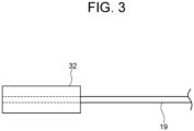
- Fig. 3 is an illustration showing a ferrule attached to an end of the fiber in Fig. 2A .
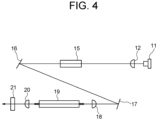
- a fiber laser apparatus 10 includes semiconductor lasers 11 and 11A, lenses 12 and 12A, a wavelength plate 13, a polarization beam splitter 14 in which a laser beam passed through the lens 12 from the semiconductor laser 11 and a laser beam passed through the lens 13A and the wavelength plate 13 from the semiconductor laser 11A and provided with a phase difference of 90 degrees, enter and are combined, an anamorphic prism pair 15 in which the laser beam from the polarization beam splitter 14 enters and emits, and total reflection mirrors 16 and 17 that totally reflects the laser beam from the anamorphic prism pair 15.
- the fiber laser apparatus 10 further includes a lens 18 in which the laser beam from the total reflection mirror 17 enters, a short-length type fiber 19 in which the laser beam from the lens 18 enters, a lens 20 in which the laser beam from the fiber 19 enters, and an emission mirror 21 that emits the laser beam from the lens 20.
- an oscillation wavelength of the semiconductor laser when an oscillation wavelength of the semiconductor laser is set to 442nm to excite the fluoride fiber, lights are emitted with strong spectrum of wavelengths of 520nm (green), 610nm (orange), and 638nm (red)).
- 638 nm is selected with coatings on an incident end face 19a of the fiber 19 and the emission mirror 21, a red fundamental wave laser beam is output.
- 610nm and 638nm are selected, orange and red fundamental wave laser beams are output.
- an apparatus constitution as such a heat exhausting means is configured so that ferrules 31 and 32 are bonded onto both ends of the fiber 19 length-shortened with addition of high-concentration active element (rare earth elements, transition elements etc., or rare earth ions (Yb, Nd, Er, Pr, Dy, Ce, Tb, etc.)) so as to absorb excitation light sufficiently, and then, the ferrules 31 and 32 and the fiber 19 are accommodated in the housing 30 in a state where the ferrules 31 and 32 are brought in contact with side plates 30c and 30d respectively on both sides of the housing 30 to suppress heat resistance as much as possible by using a heat conductive paste.
- high-concentration active element rare earth elements, transition elements etc., or rare earth ions (Yb, Nd, Er, Pr, Dy, Ce, Tb, etc.)
- the housing 30 has a structure divided into two parts, and when an upper part 30a and a lower part 30b are butted each other, the ferrules 31 and 32 are positioned at semicircular cut-out portions formed in the respective side plates 30c and 30d so as to be clamped and supported between the semicircular cut-out portions.
- the fiber 19 is inserted into a through hole of each of the ferrules 31 and 32 with the application of adhesive bond.
- the fiber 19 has a length of about 30cm or less, and the length may be 20, 15, or 10cm or less.
- the fiber 19 is made of fluoride glass material as raw material, and includes preferably a fiber core in which doping concentration of Pr element is 1500 to 5000ppm.
- the ferrules 31 and 32 By constituting the ferrules 31 and 32 from metal (for example, copper, aluminum, stainless steel, nickel, their alloys, etc.) that are high thermal conductive materials, it is possible to realize (1) efficient thermal conducting from the end portion of the fiber, (2) protecting of the fiber end portion which are apt to break easily because of being thin in diameter and weak in mechanical strength, (3) facilitating of polishing work for fiber end face, and (4) facilitating of formation of dielectric coating film onto fiber end face.
- metal for example, copper, aluminum, stainless steel, nickel, their alloys, etc.
- the housing 30 is composed of metal material (for example, copper, aluminum, stainless steel, nickel, their alloys, etc.) that are high thermal conductive materials, so that the housing 30 can efficiently conduct heat generated in the fiber 19 from the ferrules 31 and 32 brought in contact with the side plates 30c and 30d of the housing 30 to suppress thermal resistance as much as possible and can radiate such heat. For this reason, the housing 30 also functions as heat radiator. The heat radiated from the housing 30 is discharged by using a cooling fan, a water-cooling device, or a Peltier element provided in the housing 30, whereby heat accumulated in the fiber 19 can be discharged effectively.
- metal material for example, copper, aluminum, stainless steel, nickel, their alloys, etc.
- the housing 30 and the ferrules 31 and 32 are constituted from materials having a thermal expansion coefficient coinciding with or approximating to that of the raw materials of the fiber 19, whereby it is possible to prevent breakage of fiber end surface and dielectric multilayer coating surface caused by a difference in thermal expansion coefficient and generated by heat accumulation at the time of high output operation in the apparatus.
- the respective materials constituting the housing 30 and the ferrules 31 and 32 have a thermal expansion coefficient approximate to that of raw material of the fiber 19 and a high thermal conductivity, whereby it is possible to avoid problems caused by heat accumulation in the fiber due to length-shortening of the fiber.
- a fiber laser apparatus shown in Fig. 4 was used.
- This apparatus has a constitution in which the semiconductor laser 11A, the lens 12A, and the wavelength plate 13 in Fig. 1 were omitted.
- the fiber 19 was accommodated by using the ferrules 31 and 32 in the housing 30 having structure similar to that in Fig. 2 and Fig. 3 and was fixed.
- the fiber 19 was a fluoride fiber with fiber diameter of 280 ⁇ m and fiber length of 17 cm.
- Pr was doped with concentration of 3000 ppm.
- the ferrules 31 and 32 made from zirconia were mounted on both ends of the fiber 19. Each of the ferrules 31 and 32 had outside diameter of 2.5mm, length of 12mm, and inside diameter of 282 ⁇ m. After the fiber 19 was inserted into the ferrules, the fiber 19 was adhered with a resin adhesive agent. Also, the fiber 19 and the ferrules 31 and 32 are supported and fixed with the housing 30 made from aluminum for heat conducting and cooling.
- dielectric multilayer coating of high reflection with wavelength of 638nm is applied on an excitation side end face of the fiber 19 and dielectric multilayer coating of non-reflection with wavelength of 442nm is applied on the emission mirror 21, and a laser resonator is constituted with 67% of the emission mirror.
- a fiber laser output of 0.425W was attained, so that improvement of the output was confirmed.
- the fiber receives stress caused by a difference in thermal expansion coefficient from the housing and the ferrules, thus the output is decreased, and the excessive heat accumulation may lead to destruction of the fiber end surface and the coating. Accordingly, the excessive heat accumulation is a problem to be solved.
- the fiber 19 being a laser medium is a fluoride fiber and has a fiber diameter of 280 ⁇ m and a fiber length of 17cm. Pr of 3000ppm is added to the fiber core.
- the ferrules 31 and 32 made from nickel are mounted onto both ends of the fiber.
- the ferrule has an outside diameter of 2.5mm and a length of 12mm.
- the ferrule has an inside diameter of 282 ⁇ m. After the fiber was inserted into the ferrule, the fiber was adhered with a resin adhesive agent.
- the fiber 19 and the ferrules 31 and 32 are supported and fixed by the housing 30 made from copper.
- dielectric multilayer coating of high reflection with a wavelength of 638nm is applied onto an excitation side end face 19a of the fiber 19, and dielectric multilayer coating of a reflection factor of 67% with a wavelength of 638 nm is applied onto the emission mirror 21, thus a laser resonator is constituted.
- the thermal conductivities of fluoride fiber, nickel, and copper are 0.898W/mK, 91W/mK, and 403W/mK, respectively.
- the thermal expansion coefficients of fluoride fiber, nickel, and copper are 18.6 ⁇ 10 -6 /K, 13.4 ⁇ 10 -6 /K, and 16.5 ⁇ 10 -6 /K, respectively.
- Nickel and copper have a high thermal conductivity while having a thermal expansion coefficient approximate to that of the fluoride fiber.
- the fiber laser output (a wavelength of 638nm) of 1.0W with an efficiency of about 20% was obtained relative to the excitation semiconductor laser input of 5.0W with a wavelength of 442nm, and the output was not saturated.
- the laser output was saturated with the fiber laser output of 0.425W relative to the excitation semiconductor laser input of 2.5W, and an output more than that was not obtained. This is caused by decrease in absorption coefficient relative to the wavelength of the excitation semiconductor laser, decrease in induced emission cross section of the fiber material, and increase in propagation loss, because heat is accumulated in the fiber to increase the temperature due to the low thermal conductivity of the ferrule made from zirconia.
- the ferrule and the housing each having high thermal conductivity and thermal expansion coefficient approximate to that of the fiber material are replaced in the present example, whereby the increase of the laser output and the improvement of the efficiency were attained.
- the embodiment and the example for executing the present invention have been described.
- the present invention should not be limited to these embodiment and example, and various kinds of modification are possible within the scope of the present invention, which is determined by the claims.
- the constitution of the fiber laser apparatus shown in Fig. 1 is an example, and hence other constitution may be permissible.
- the materials that constitute the ferrule and the housing can be used as the materials that constitute the ferrule and the housing, if the thermal expansion coefficient is approximate to the thermal expansion coefficient of the fiber and it has a high thermal conductivity of, for example, 90W/mK or more.
- the fiber laser apparatus of the present invention since it is possible to avoid the problem caused by heat accumulation in the fiber that arises due to shortening length of the fiber, downsized apparatus can be realized and provided in response to the strong social request.
Landscapes
- Physics & Mathematics (AREA)
- Electromagnetism (AREA)
- Engineering & Computer Science (AREA)
- Optics & Photonics (AREA)
- Plasma & Fusion (AREA)
- Microelectronics & Electronic Packaging (AREA)
- General Physics & Mathematics (AREA)
- Optical Couplings Of Light Guides (AREA)
- Lasers (AREA)
Description
- The present invention relates to a fiber laser apparatus that can be configured in small size and compact form.
- A conventional constitution example of a fiber laser apparatus using an optical fiber to which active element (rare earth elements, transition elements, or rare earth ions (Yb, Nd, Er, Pr, Dy, Ce, Tb, etc.)) is added, is shown in
Fig. 7 . This conventional example includes afiber 2 in a circular form in which a gain fiber with a length of a degree exceeding 10m is wound up and wound around, aferrule 1 made from zirconia and provided on input and output ends of thefiber 2 in order to support thefiber 2 that tends to break easily because of being thin in thickness and weak in mechanical strength, a substrate andradiator 3 to support thefiber 2 and for discharging heat, and a cooling fan (or water-cooling device) 4. There may be a case where nickel or stainless steel is used for theferrule 1 to weld and fix the tip of the fiber. In order to make the laser apparatus as compact as possible, thefiber 2 is wound around, and in order to improve cooling efficiency, the fiber is kept from overlapping with each other. A diameter of a circle in which the fiber is wound around is about 30 cm or less. The substrate andradiator 3 and thefiber 2 come in contact with each other in such state that heat resistance is suppressed as much as possible by using heat conductive paste. In the substrate andradiator 3, heat accumulated in thefiber 2 is discharged by using the cooling fan (or water-cooling device) 4 or a Peltier element. The doping concentration of rare earth in thefiber 2 is made low concentration and its strip length is made long, thereby to obtain two items of increase of the cooling surface and increase of the dispersion effect of heat accumulation in the direction of the fiber length, and it becomes possible to perform efficient cooling. -
Patent Literature 1 discloses an optical fiber laser apparatus in which one long laser fiber wounded around by multiple times is embedded and fixed without clearance in transparent ultraviolet curable resin in form of a rectangular parallelepiped shape, and both ends of the laser fiber are exposed outside. -
Patent Literature 2 describes that excitation light output by an excitation laser element is incident to a core of an aluminum fluoride-based fiber doped with Pr3+ while being condensed by an optical system for coupling and undergoing beam forming. Fluorescence discharged from the Pr3+ in the core, which has been excited by the excitation light, is resonated selectively by a pair of resonating elements formed by wavelength selective reflective films and forms a laser output. The fiber is formed from the core, cladding, and a sheath, is covered and protected by a metal tube, and has temperature increases suppressed. -
Patent Literature 3 describes a fiber laser having a thermal controller operatively connected to one or more fiber Bragg gratings (FBGs). The thermal controller does not impart much or imparts very little mechanical stress or strain to the optical fiber in which the FBGs reside because such forces can alter the FBG performance. Rather, the thermal controller utilizes a thermally conductive semi-solid or non-Newtonian fluid to submerge/suspend a portion of the optical fiber in which FBG resides. Temperature control logic controls whether a thermoelectric heater and cooler should be directed to increase or decrease its temperature. The thermoelectric heater and cooler imparts or removes thermal energy from the FBG to efficiently control its performance without the application of mechanical stress. The fiber laser having a thermal controller generally is able to increase laser output power greater than two times the amount of output power of a similarly fabricated fiber laser free of the thermal controller(s). -
Patent Literature 4 describes a CW fiber-laser including a gain fiber having a reflector proximity-coupled to one end, with the other end left uncoated. A laser resonator is defined by the reflector and the uncoated end of the gain-fiber. Pump-radiation from two fast-axis diode-laser bar stacks is combined and focused into the uncoated end of the gain-fiber for energizing the fiber. Laser radiation resulting from the energizing is delivered from the uncoated end of the gain-fiber and separated from the pump-radiation by a dichroic minor. - Non-Patent Literature 1 describes a set of guidelines for the practical design of lensed fiber for the optical coupling of semiconductor lasers in butterfly packages using laser welding. These guidelines have optimized the tradeoff between coupling efficiency and alignment tolerance. Moreover, a radius of curvature of 11 mum is shown to be optimal for semiconductor lasers whose divergence angles range from 5deg to 30deg. To experimentally evaluate the design, lensed fibers were assembled by a Nd:YAG laser welding technique in conventional butterfly packages and their coupling efficiencies were 28%-72% without horizontal misalignment compensation.
-
- Patent Literature 1:
JP H10-135548A - Patent Literature 2:
WO 2014/157119 A1 - Patent Literature 3:
US 9 667 025 B2 - Patent Literature 4:
US 2012/230352 A1 - Non-Patent Literature 1: Jeong Hwan Song et al. : "Practical Design of Lensed Fibers for Semiconductor Laser Packaging Using Laser Welding Technique", Journal of Lightwave Technology, IEEE, USA, vol. 27, no. 11, 1 June 2009, pages 1533-1359
- In the conventional fiber laser apparatus shown in
Fig. 7 , since a gain fiber with length of about 10m is used, it is necessary to wind around the fiber, and hence small and compact design smaller than the winding-around diameter is difficult, so that there has been a limit in making the apparatus in small compact structure. The optical fiber laser apparatus ofPatent Literature 1 is also in the similar situation, also, in the structure where the long laser fiber wounded around by multiple times is embedded without clearance in the ultraviolet curable resin, the heat exhausting efficiency is lowered. - The small compact apparatus constitution is a subject originated from social request. In order to solve this subject, to shorten the length of the fiber (about 30cm or less, or 20, 15 or 10cm or less may be permissible) is required. For the purpose of shortening the length, it is necessary to use a gain fiber to which active element (rare earth elements, transition elements, or rare earth ions (Yb, Nd, Er, Pr, Dy, Ce, Tb, etc.)) is added with higher concentration than that of the conventional apparatus. However, when the fiber length is shortened, a problem arise in heat accumulation in the fiber.
- An object of the present invention is to provide a fiber laser apparatus that can avoid a problem caused by heat accumulation in the fiber, arising due to the shortening of the fiber to downsize the apparatus.
- In order to realize at least one of the above-mentioned object, a fiber laser apparatus that reflects one aspect of the present invention is a fiber laser apparatus as defined in
claim 1. - According to the fiber laser apparatus, since the housing and the two ferrules are composed of a material with a thermal expansion coefficient approximate to that of a raw material of the fiber, it is possible to reduce heat accumulation in an end portion of the fiber during the apparatus operation, to avoid problems caused by the heat accumulation. Namely, since the housing and the two ferrules may be composed of a material having a high thermal conductivity, the thermal conductivity is increased than that of the conventional material, for example, ceramics, such as zirconia and the like. Accordingly, heat accumulation on the end portions of the fiber can be reduced. Also, since the material has a thermal expansion coefficient approximate to that of the raw material of the fiber, even if the fiber accumulates heat, it is possible to reduce the stress received from the housing and the two ferrules due to a difference in the thermal expansion coefficients. In this way, since the problem caused by the heat accumulation of the fiber due to the shortening of the fiber can be prevented, it is possible to realize downsizing of the apparatus by shortening of the fiber.
- According to an embodiment, the two ferrules and the housing are composed of a material having an optional thermal conductivity of 90W/mK or more and the first thermal expansion coefficient is 10×10-6 to 30×10-6/K.
- According to this embodiment, since the two ferrules and the housing are composed of a material that may have a thermal conductivity of 90 W/mK or more and a first thermal expansion coefficient of 10×10-6 to 30×10-6/K, it is possible to reduce heat accumulation in an end portion of the fiber during the apparatus operation, to avoid problems caused by the heat accumulation. Namely, when the housing and the two ferrules are composed of a metal material having a high thermal conductivity of 90 W/mK or more, the thermal conductivity is increased than that of the conventional material, for example, ceramics, such as zirconia and the like. Accordingly, heat accumulation on the end portions of the fiber can be reduced. Also, since the material has a thermal expansion coefficient of 10×10-6 to 30×10-6/K approximate to that of the raw material of the fiber, even if the fiber accumulates heat, it is possible to reduce the stress received from the housing and the two ferrules due to a difference in the thermal expansion coefficients. In this way, since the problem caused by the heat accumulation of the fiber due to the shortening of the fiber can be prevented, it is possible to realize downsizing of the apparatus by shortening of the fiber.
- In the above-mentioned fiber laser apparatus, it is preferable that the fiber has a length of 300 mm or less, the raw material of the fiber is a fluoride glass material, and the fiber includes a fiber core in which a doping concentration of Pr element is 1500 to 5000ppm.
- Also, it is preferable that the above-mentioned fiber laser apparatus is configured to perform a laser oscillation with any one or two of wavelengths of 520 nm ± 10 nm, 610 nm ± 10 nm, and 638 nm ± 10 nm.
- According to the fiber laser apparatus of the present invention, since the problem caused by heat accumulation of the fiber due to shortening of the fiber can be avoided, it becomes possible to realize downsizing of the apparatus.
-
- [
FIG. 1] Fig. 1 is an optical path diagram showing schematically a fiber laser apparatus according to the present embodiment. - [
FIG. 2A-2B] Fig. 2A is a front view showing schematically a housing to accommodate the fiber shown inFig. 1 , and -
Fig. 2B is a side view showing schematically the housing. - [
FIG. 3] Fig. 3 is an illustration showing a ferrule attached to an end of the fiber shown inFig. 2(a) . - [
FIG. 4] Fig. 4 is an optical path diagram showing schematically a fiber laser apparatus used in the present preliminary study example. - [
FIG. 5] Fig. 5 is a graph showing the fundamental wave output characteristics of the fiber laser apparatus shown inFig. 4 and obtained by the present preliminary study example. - [
FIG. 6] Fig. 6 is a graph showing the fundamental wave output characteristics of the fiber laser apparatus shown inFig. 1 and obtained by the present example. - [
FIG. 7] Fig. 7 is a drawing showing a principal part of a conventional fiber laser apparatus. - Hereinafter, an embodiment for executing the present invention will be described with reference to drawings.
Fig. 1 is an optical path diagram showing schematically a fiber laser apparatus according to the present embodiment.Fig. 2A is a front view showing schematically a housing in which a fiber inFig. 1 is accommodated, andFig. 2B is a side elevation showing schematically the housing.Fig. 3 is an illustration showing a ferrule attached to an end of the fiber inFig. 2A . - As shown in
Fig. 1 , afiber laser apparatus 10 according to the present embodiment includessemiconductor lasers lenses wavelength plate 13, apolarization beam splitter 14 in which a laser beam passed through thelens 12 from thesemiconductor laser 11 and a laser beam passed through the lens 13A and thewavelength plate 13 from thesemiconductor laser 11A and provided with a phase difference of 90 degrees, enter and are combined, ananamorphic prism pair 15 in which the laser beam from thepolarization beam splitter 14 enters and emits, and total reflection mirrors 16 and 17 that totally reflects the laser beam from theanamorphic prism pair 15. - The
fiber laser apparatus 10 further includes alens 18 in which the laser beam from thetotal reflection mirror 17 enters, a short-length type fiber 19 in which the laser beam from thelens 18 enters, alens 20 in which the laser beam from thefiber 19 enters, and anemission mirror 21 that emits the laser beam from thelens 20. - For example, when an oscillation wavelength of the semiconductor laser is set to 442nm to excite the fluoride fiber, lights are emitted with strong spectrum of wavelengths of 520nm (green), 610nm (orange), and 638nm (red)). Where, for example, 638 nm is selected with coatings on an
incident end face 19a of thefiber 19 and theemission mirror 21, a red fundamental wave laser beam is output. Also, for example, where 610nm and 638nm are selected, orange and red fundamental wave laser beams are output. - In order to design the
fiber laser apparatus 10 with a smaller compact structure, it is required to shorten the fiber length by making concentration of rare earth element in the gain fiber higher. For that purpose, a heat exhausting means capable of effectively avoiding heat accumulation in thefiber 19 caused by the length shortening, becomes a problem to be solved. - As shown in
Figs. 2A and 2B , an apparatus constitution as such a heat exhausting means is configured so thatferrules fiber 19 length-shortened with addition of high-concentration active element (rare earth elements, transition elements etc., or rare earth ions (Yb, Nd, Er, Pr, Dy, Ce, Tb, etc.)) so as to absorb excitation light sufficiently, and then, theferrules fiber 19 are accommodated in thehousing 30 in a state where theferrules side plates housing 30 to suppress heat resistance as much as possible by using a heat conductive paste. - That is, as shown in
Figs. 2A and 2B , thehousing 30 has a structure divided into two parts, and when anupper part 30a and alower part 30b are butted each other, theferrules respective side plates Figs. 2A and 2B andFig.3 , thefiber 19 is inserted into a through hole of each of theferrules - The
fiber 19 has a length of about 30cm or less, and the length may be 20, 15, or 10cm or less. Also, for example, thefiber 19 is made of fluoride glass material as raw material, and includes preferably a fiber core in which doping concentration of Pr element is 1500 to 5000ppm. - By constituting the
ferrules - Also, the
housing 30 is composed of metal material (for example, copper, aluminum, stainless steel, nickel, their alloys, etc.) that are high thermal conductive materials, so that thehousing 30 can efficiently conduct heat generated in thefiber 19 from theferrules side plates housing 30 to suppress thermal resistance as much as possible and can radiate such heat. For this reason, thehousing 30 also functions as heat radiator. The heat radiated from thehousing 30 is discharged by using a cooling fan, a water-cooling device, or a Peltier element provided in thehousing 30, whereby heat accumulated in thefiber 19 can be discharged effectively. - Moreover, the
housing 30 and theferrules fiber 19, whereby it is possible to prevent breakage of fiber end surface and dielectric multilayer coating surface caused by a difference in thermal expansion coefficient and generated by heat accumulation at the time of high output operation in the apparatus. - As mentioned above, the respective materials constituting the
housing 30 and theferrules fiber 19 and a high thermal conductivity, whereby it is possible to avoid problems caused by heat accumulation in the fiber due to length-shortening of the fiber. - Next, the present invention is described concretely on the basis of the example and the preliminary study example. The present invention should not be limited to the example.
- First, the preliminary study example having studied in advance with regard to the present invention is described. In this preliminary study example, a fiber laser apparatus shown in
Fig. 4 was used. This apparatus has a constitution in which thesemiconductor laser 11A, thelens 12A, and thewavelength plate 13 inFig. 1 were omitted. Thefiber 19 was accommodated by using theferrules housing 30 having structure similar to that inFig. 2 andFig. 3 and was fixed. - The
fiber 19 was a fluoride fiber with fiber diameter of 280µm and fiber length of 17 cm. In the fiber core, Pr was doped with concentration of 3000 ppm. Theferrules fiber 19. Each of theferrules fiber 19 was inserted into the ferrules, thefiber 19 was adhered with a resin adhesive agent. Also, thefiber 19 and theferrules housing 30 made from aluminum for heat conducting and cooling. With this structure, dielectric multilayer coating of high reflection with wavelength of 638nm is applied on an excitation side end face of thefiber 19 and dielectric multilayer coating of non-reflection with wavelength of 442nm is applied on theemission mirror 21, and a laser resonator is constituted with 67% of the emission mirror. According to such constitution, as shown inFig. 5 , a fiber laser output of 0.425W was attained, so that improvement of the output was confirmed. However, phenomenon that the output (wavelength of 638nm) was saturated in the excitation semiconductor laser input of 2.5W with wavelength of 442 nm, was observed. - It is a thermal saturation phenomenon caused by heat accumulation in the fiber end surface that it is considered as the cause. In the constitution of the conventional fiber laser apparatus shown in
Fig. 7 , since the active element doping concentration in the gain fiber is low, any problem does not occur. But, by shortening the fiber length for downsizing, remarkable heat accumulation becomes to appear on the excitation end surface of the fiber. - In the case where the laser operation is performed for a long time, temperature will rise in the ferrule itself. Therefore, a mechanism for dissipating the heat in the ferrule efficiently is needed. On the other hand, when the temperature at the tip of the fiber rises, the refractive index of the fiber will change. The light transmitting in the inside of the fiber is confined by a difference in refractive index between core material and cladding material. But, since the refractive index changes due to change of temperature vary the difference in refractive index, the mode in which the light propagates in the inside of the fiber varies. In the case where temperatures in the tip portion and the central portion of the fiber are different from each other, the propagation mode changes while the light is propagating in the inside of the fiber. Thus, a part of the light cannot propagate and is emitted out of the fiber. As a result, the temperature change in the propagating direction of the light in the fiber causes a decrease in transmission efficiency. Therefore, a mechanism for making the temperature uniform by dissipating the heat in the tip portion and diffusing the heat to the whole fiber, is needed. It is thought that a decrease in absorption coefficient relative to excitation light, a decrease in induced emission cross section, a shift in oscillation wavelength, an increase in loss by refractive index change, a deterioration in beam quality by heat birefringence, and the like, take place due to these causes, and a thermal saturation phenomenon appears.
- Also, due to the excessive heat accumulation, the fiber receives stress caused by a difference in thermal expansion coefficient from the housing and the ferrules, thus the output is decreased, and the excessive heat accumulation may lead to destruction of the fiber end surface and the coating. Accordingly, the excessive heat accumulation is a problem to be solved.
- In order to reduce the thermal saturation phenomena that has become clear in the above-described preliminary study example, the following improvement has been made in the present example.
- (1) As the ferrule for supporting the fiber end surface, a metallic ferrule with higher thermal conductivity was used in place of ceramics.
- (2) In order to prevent breakage of a fiber end surface and a dielectric multilayer coating surface resulting from a difference in thermal expansion coefficient caused by the heat accumulation upon high output operation, materials having thermal expansion coefficients coincident with or approximate to each other were selected as each material of the fluoride fiber, the ferrule, and the housing.
- Concretely, in
Fig. 1 to Fig. 3 , thefiber 19 being a laser medium is a fluoride fiber and has a fiber diameter of 280µm and a fiber length of 17cm. Pr of 3000ppm is added to the fiber core. Onto both ends of the fiber, theferrules fiber 19 and theferrules housing 30 made from copper. With this structure, dielectric multilayer coating of high reflection with a wavelength of 638nm is applied onto an excitationside end face 19a of thefiber 19, and dielectric multilayer coating of a reflection factor of 67% with a wavelength of 638 nm is applied onto theemission mirror 21, thus a laser resonator is constituted. - The thermal conductivities of fluoride fiber, nickel, and copper are 0.898W/mK, 91W/mK, and 403W/mK, respectively. Moreover, the thermal expansion coefficients of fluoride fiber, nickel, and copper are 18.6×10⁻⁶/K, 13.4×10⁻⁶/K, and 16.5×10⁻⁶/K, respectively. Nickel and copper have a high thermal conductivity while having a thermal expansion coefficient approximate to that of the fluoride fiber. As a result, as shown in
Fig. 6 , the fiber laser output (a wavelength of 638nm) of 1.0W with an efficiency of about 20% was obtained relative to the excitation semiconductor laser input of 5.0W with a wavelength of 442nm, and the output was not saturated. - In the structure in which zirconia material was used for the ferrule and aluminum material was used for the housing as described in the preliminary study example, the laser output was saturated with the fiber laser output of 0.425W relative to the excitation semiconductor laser input of 2.5W, and an output more than that was not obtained. This is caused by decrease in absorption coefficient relative to the wavelength of the excitation semiconductor laser, decrease in induced emission cross section of the fiber material, and increase in propagation loss, because heat is accumulated in the fiber to increase the temperature due to the low thermal conductivity of the ferrule made from zirconia. On the other hand, the ferrule and the housing each having high thermal conductivity and thermal expansion coefficient approximate to that of the fiber material are replaced in the present example, whereby the increase of the laser output and the improvement of the efficiency were attained.
- As mentioned in the above, the embodiment and the example for executing the present invention have been described. The present invention should not be limited to these embodiment and example, and various kinds of modification are possible within the scope of the present invention, which is determined by the claims. For example, the constitution of the fiber laser apparatus shown in
Fig. 1 is an example, and hence other constitution may be permissible. - Also, other materials can be used as the materials that constitute the ferrule and the housing, if the thermal expansion coefficient is approximate to the thermal expansion coefficient of the fiber and it has a high thermal conductivity of, for example, 90W/mK or more.
- According to the fiber laser apparatus of the present invention, since it is possible to avoid the problem caused by heat accumulation in the fiber that arises due to shortening length of the fiber, downsized apparatus can be realized and provided in response to the strong social request.
-
- 10
- fiber laser apparatus
- 11, 11A
- semiconductor laser
- 19
- fiber
- 30
- housing
- 30a
- upper portion
- 30b
- lower portion
- 30c, 30d
- side plate
- 31, 32
- ferrule
Claims (6)
- A fiber laser apparatus (10) comprising:a short length type fiber (19) to which an active element is added and that has a length of 300 mm or less;two ferrules (31, 32) attached to both ends of the fiber (19); anda housing (30) comprising an upper part (30a) and a lower part (30b) that respectively have semicircular cut-out portions butted against each other to form a hole, and configured to accommodate the fiber (19) and support the fiber (19) in the hole with the two ferrules (31, 32),wherein an outer circumference of each of the two ferrules (31, 32) contacts an inner circumference of the hole such that the housing (30) discharges heat generated in the fiber (19) from side plates (30c, 30d) of the housing (30),wherein a part of each of the two ferrules (31, 32) protrudes outside from each of the side plates (30c, 30d),wherein the fiber (19) has a coating film formed on at least one (19a) of the ends of the fiber (19), the ends of the fiber (19) being respectively located at ends of the two ferrules (31, 32),wherein each of the housing (30) and the two ferrules (31, 32) is composed of a material having a first thermal expansion coefficient that is equal to or has a predetermined difference from a second thermal expansion coefficient of a raw material of the fiber (19), andwherein the predetermined difference between the first and second thermal expansion coefficient is within - 8.6×10⁻⁶ to 11.4×10⁻⁶/K.
- The fiber laser apparatus (10) according to claim 1,
wherein the first thermal expansion coefficient is 10 ×10-6 to 30×10-6/K. - The fiber laser apparatus (10) according to claim 2, wherein the material of the housing (30) and the ferrule (31, 32) has a thermal conductivity of 90W/mK or more.
- The fiber laser apparatus (10) according to any one of claims 1 to 3, wherein the raw material of the fiber (19) is a fluoride glass material.
- The fiber laser apparatus (10) according to claim 4, wherein the active element is Pr and is included in a fiber core of the fiber (19) at a doping concentration of 1500 to 5000ppm.
- The fiber laser apparatus (10) according to any one of claims 1 to 5, wherein the fiber laser apparatus (10) is configured to perform laser oscillation with any one or two of wavelengths of 520nm ± 10nm, 610nm ± 10nm, and 638nm ± 10nm.
Applications Claiming Priority (2)
| Application Number | Priority Date | Filing Date | Title |
|---|---|---|---|
| JP2019138108A JP6836043B2 (en) | 2019-07-26 | 2019-07-26 | Fiber laser device |
| PCT/JP2020/027994 WO2021020188A1 (en) | 2019-07-26 | 2020-07-20 | Fibre laser device |
Publications (3)
| Publication Number | Publication Date |
|---|---|
| EP4007089A1 EP4007089A1 (en) | 2022-06-01 |
| EP4007089A4 EP4007089A4 (en) | 2023-08-30 |
| EP4007089B1 true EP4007089B1 (en) | 2024-09-04 |
Family
ID=74229046
Family Applications (1)
| Application Number | Title | Priority Date | Filing Date |
|---|---|---|---|
| EP20848206.7A Active EP4007089B1 (en) | 2019-07-26 | 2020-07-20 | Fibre laser device |
Country Status (5)
| Country | Link |
|---|---|
| US (1) | US11621535B2 (en) |
| EP (1) | EP4007089B1 (en) |
| JP (1) | JP6836043B2 (en) |
| CN (1) | CN114008872A (en) |
| WO (1) | WO2021020188A1 (en) |
Family Cites Families (22)
| Publication number | Priority date | Publication date | Assignee | Title |
|---|---|---|---|---|
| JP3920384B2 (en) | 1996-10-31 | 2007-05-30 | 憲一 植田 | Optical fiber laser equipment |
| US6263143B1 (en) * | 1998-10-15 | 2001-07-17 | Lucent Technologies Inc. | Package housing for laser module wound on a spool |
| WO2000033116A1 (en) * | 1998-12-02 | 2000-06-08 | Corning Incorporated | A detachable plug-in pump card assembly |
| JP2002022972A (en) * | 2000-07-05 | 2002-01-23 | Sumitomo Electric Ind Ltd | Optical part |
| JP2004214325A (en) * | 2002-12-27 | 2004-07-29 | Toshiba Corp | Optical fiber heat sink and manufacturing method thereof |
| US8483247B2 (en) * | 2004-06-30 | 2013-07-09 | Google Inc. | Thermally controlled external cavity tuneable laser |
| CA2533674A1 (en) * | 2006-01-23 | 2007-07-23 | Itf Technologies Optiques Inc./Itf Optical Technologies Inc. | Optical fiber component package for high power dissipation |
| JP2009116076A (en) * | 2007-11-07 | 2009-05-28 | Mitsubishi Electric Corp | Optical fiber fused part holding structure |
| US8542971B2 (en) * | 2008-06-25 | 2013-09-24 | Coractive High-Tech Inc. | Packages for high power operation of optical fiber components |
| JP2010141283A (en) * | 2008-07-08 | 2010-06-24 | Central Glass Co Ltd | Wide-band wavelength-variable laser device |
| JP5308175B2 (en) * | 2009-02-03 | 2013-10-09 | 三星ダイヤモンド工業株式会社 | Optical fiber cooling equipment |
| JP2010224303A (en) | 2009-03-24 | 2010-10-07 | Nissei Electric Co Ltd | Terminal processed optical fiber |
| US9083140B2 (en) * | 2011-03-10 | 2015-07-14 | Coherent, Inc. | High-power CW fiber-laser |
| EP2715887A4 (en) * | 2011-06-03 | 2016-11-23 | Foro Energy Inc | Rugged passively cooled high power laser fiber optic connectors and methods of use |
| JP5588534B1 (en) * | 2013-03-28 | 2014-09-10 | 三星ダイヤモンド工業株式会社 | Optical fiber and laser oscillator using the same |
| JP2014199863A (en) * | 2013-03-29 | 2014-10-23 | ウシオ電機株式会社 | Fiber laser light source device |
| JP2015018984A (en) * | 2013-07-12 | 2015-01-29 | ウシオ電機株式会社 | Fiber laser light source device |
| JP2015065189A (en) * | 2013-09-24 | 2015-04-09 | ウシオ電機株式会社 | Fiber laser light source device |
| JP2015179761A (en) * | 2014-03-19 | 2015-10-08 | ウシオ電機株式会社 | fiber laser device |
| US9667025B2 (en) * | 2015-04-06 | 2017-05-30 | Bae Systems Information And Electronic Systems Integration Inc. | System and method for increasing power emitted from a fiber laser |
| DE102015013689A1 (en) * | 2015-10-21 | 2017-04-27 | Trumpf Laser Gmbh | Fiber support unit and fiber receiving element |
| JP6968110B2 (en) | 2017-02-10 | 2021-11-17 | 富士フイルム株式会社 | Optical connector and photoacoustic wave generator |
-
2019
- 2019-07-26 JP JP2019138108A patent/JP6836043B2/en active Active
-
2020
- 2020-07-20 EP EP20848206.7A patent/EP4007089B1/en active Active
- 2020-07-20 WO PCT/JP2020/027994 patent/WO2021020188A1/en unknown
- 2020-07-20 CN CN202080045724.1A patent/CN114008872A/en active Pending
-
2021
- 2021-12-14 US US17/644,208 patent/US11621535B2/en active Active
Also Published As
| Publication number | Publication date |
|---|---|
| US20220109280A1 (en) | 2022-04-07 |
| EP4007089A4 (en) | 2023-08-30 |
| JP6836043B2 (en) | 2021-02-24 |
| JP2021022654A (en) | 2021-02-18 |
| WO2021020188A1 (en) | 2021-02-04 |
| EP4007089A1 (en) | 2022-06-01 |
| US11621535B2 (en) | 2023-04-04 |
| CN114008872A (en) | 2022-02-01 |
Similar Documents
| Publication | Publication Date | Title |
|---|---|---|
| US6801550B1 (en) | Multiple emitter side pumping method and apparatus for fiber lasers | |
| US9214781B2 (en) | Fiber amplifier system for suppression of modal instabilities and method | |
| US6751241B2 (en) | Multimode fiber laser gratings | |
| JP3433900B2 (en) | Optical communication system including cladding pumped fiber laser | |
| US10431951B2 (en) | Leakage light removal structure and fiber laser | |
| EP3104201B1 (en) | Structure for eliminating excess light, and fiber laser | |
| WO2012122012A2 (en) | High-power cw fiber-laser | |
| JP2004527101A (en) | Fiber laser | |
| WO2015087983A1 (en) | Laser device and optical fiber laser | |
| JP5342255B2 (en) | Optical fiber laser | |
| Carter et al. | Damage mechanisms in components for fiber lasers and amplifiers | |
| EP3188327B1 (en) | Optical fiber device | |
| US20220285903A1 (en) | Optical amplification apparatus | |
| EP4007089B1 (en) | Fibre laser device | |
| US20220385025A1 (en) | Ultraviolet laser apparatus | |
| JP2009069492A (en) | Optical fiber and optical apparatus | |
| JP3228451B2 (en) | Optical fiber amplifier | |
| CN108603983B (en) | Optical module and light output device | |
| WO2006098313A1 (en) | Optical amplifier and laser device | |
| JP2009212184A (en) | Fiber laser device | |
| JP2007123594A (en) | Optical-fiber optical amplifier and optical-fiber laser apparatus using same | |
| JP2001015834A (en) | Manufacture of laser beam generating device and optical amplifier | |
| JP2001015835A (en) | Laser beam generating device and optical amplifier | |
| WO2020241363A1 (en) | Optical fiber device | |
| WO2020241398A1 (en) | Optical fiber and laser device |
Legal Events
| Date | Code | Title | Description |
|---|---|---|---|
| STAA | Information on the status of an ep patent application or granted ep patent |
Free format text: STATUS: THE INTERNATIONAL PUBLICATION HAS BEEN MADE |
|
| PUAI | Public reference made under article 153(3) epc to a published international application that has entered the european phase |
Free format text: ORIGINAL CODE: 0009012 |
|
| STAA | Information on the status of an ep patent application or granted ep patent |
Free format text: STATUS: REQUEST FOR EXAMINATION WAS MADE |
|
| 17P | Request for examination filed |
Effective date: 20220126 |
|
| AK | Designated contracting states |
Kind code of ref document: A1 Designated state(s): AL AT BE BG CH CY CZ DE DK EE ES FI FR GB GR HR HU IE IS IT LI LT LU LV MC MK MT NL NO PL PT RO RS SE SI SK SM TR |
|
| DAV | Request for validation of the european patent (deleted) | ||
| DAX | Request for extension of the european patent (deleted) | ||
| A4 | Supplementary search report drawn up and despatched |
Effective date: 20230728 |
|
| RIC1 | Information provided on ipc code assigned before grant |
Ipc: H01S 3/067 20060101ALI20230724BHEP Ipc: H01S 3/042 20060101AFI20230724BHEP |
|
| GRAP | Despatch of communication of intention to grant a patent |
Free format text: ORIGINAL CODE: EPIDOSNIGR1 |
|
| STAA | Information on the status of an ep patent application or granted ep patent |
Free format text: STATUS: GRANT OF PATENT IS INTENDED |
|
| INTG | Intention to grant announced |
Effective date: 20240604 |
|
| RIN1 | Information on inventor provided before grant (corrected) |
Inventor name: HAMADA, TAKESHI Inventor name: NAKAHARA, MASAMORI Inventor name: MOTOKOSHI, SHINJI Inventor name: BINUN, PAUL Inventor name: FUJIMOTO, YASUSHI |
|
| GRAS | Grant fee paid |
Free format text: ORIGINAL CODE: EPIDOSNIGR3 |
|
| GRAA | (expected) grant |
Free format text: ORIGINAL CODE: 0009210 |
|
| STAA | Information on the status of an ep patent application or granted ep patent |
Free format text: STATUS: THE PATENT HAS BEEN GRANTED |
|
| AK | Designated contracting states |
Kind code of ref document: B1 Designated state(s): AL AT BE BG CH CY CZ DE DK EE ES FI FR GB GR HR HU IE IS IT LI LT LU LV MC MK MT NL NO PL PT RO RS SE SI SK SM TR |
|
| REG | Reference to a national code |
Ref country code: GB Ref legal event code: FG4D |
|
| REG | Reference to a national code |
Ref country code: CH Ref legal event code: EP |