JP6836043B2 - Fiber laser device - Google Patents
Fiber laser device Download PDFInfo
- Publication number
- JP6836043B2 JP6836043B2 JP2019138108A JP2019138108A JP6836043B2 JP 6836043 B2 JP6836043 B2 JP 6836043B2 JP 2019138108 A JP2019138108 A JP 2019138108A JP 2019138108 A JP2019138108 A JP 2019138108A JP 6836043 B2 JP6836043 B2 JP 6836043B2
- Authority
- JP
- Japan
- Prior art keywords
- fiber
- ferrule
- housing
- thermal expansion
- coefficient
- Prior art date
- Legal status (The legal status is an assumption and is not a legal conclusion. Google has not performed a legal analysis and makes no representation as to the accuracy of the status listed.)
- Active
Links
- 239000000835 fiber Substances 0.000 title claims description 171
- 239000000463 material Substances 0.000 claims description 35
- 239000005383 fluoride glass Substances 0.000 claims description 3
- 239000002023 wood Substances 0.000 claims description 2
- 238000009825 accumulation Methods 0.000 description 18
- PXHVJJICTQNCMI-UHFFFAOYSA-N Nickel Chemical compound [Ni] PXHVJJICTQNCMI-UHFFFAOYSA-N 0.000 description 10
- MCMNRKCIXSYSNV-UHFFFAOYSA-N Zirconium dioxide Chemical compound O=[Zr]=O MCMNRKCIXSYSNV-UHFFFAOYSA-N 0.000 description 10
- 238000001816 cooling Methods 0.000 description 10
- 239000004065 semiconductor Substances 0.000 description 10
- 238000004904 shortening Methods 0.000 description 10
- 229910052761 rare earth metal Inorganic materials 0.000 description 8
- 230000005284 excitation Effects 0.000 description 7
- KRHYYFGTRYWZRS-UHFFFAOYSA-M Fluoride anion Chemical compound [F-] KRHYYFGTRYWZRS-UHFFFAOYSA-M 0.000 description 6
- RYGMFSIKBFXOCR-UHFFFAOYSA-N Copper Chemical compound [Cu] RYGMFSIKBFXOCR-UHFFFAOYSA-N 0.000 description 5
- 229910052802 copper Inorganic materials 0.000 description 5
- 239000010949 copper Substances 0.000 description 5
- 239000011162 core material Substances 0.000 description 5
- 230000007423 decrease Effects 0.000 description 5
- 229910052759 nickel Inorganic materials 0.000 description 5
- 229910052782 aluminium Inorganic materials 0.000 description 4
- XAGFODPZIPBFFR-UHFFFAOYSA-N aluminium Chemical compound [Al] XAGFODPZIPBFFR-UHFFFAOYSA-N 0.000 description 4
- 238000010586 diagram Methods 0.000 description 4
- 239000007888 film coating Substances 0.000 description 4
- 238000009501 film coating Methods 0.000 description 4
- 239000011347 resin Substances 0.000 description 4
- 229920005989 resin Polymers 0.000 description 4
- 229910052779 Neodymium Inorganic materials 0.000 description 3
- 229910052771 Terbium Inorganic materials 0.000 description 3
- 239000000853 adhesive Substances 0.000 description 3
- 230000001070 adhesive effect Effects 0.000 description 3
- 230000008859 change Effects 0.000 description 3
- 239000011248 coating agent Substances 0.000 description 3
- 238000000576 coating method Methods 0.000 description 3
- 230000006378 damage Effects 0.000 description 3
- 239000002657 fibrous material Substances 0.000 description 3
- 230000006872 improvement Effects 0.000 description 3
- 230000003287 optical effect Effects 0.000 description 3
- 239000013307 optical fiber Substances 0.000 description 3
- -1 rare earth ion Chemical class 0.000 description 3
- 229920006395 saturated elastomer Polymers 0.000 description 3
- 239000010935 stainless steel Substances 0.000 description 3
- 229910001220 stainless steel Inorganic materials 0.000 description 3
- 239000000758 substrate Substances 0.000 description 3
- 230000007704 transition Effects 0.000 description 3
- XLYOFNOQVPJJNP-UHFFFAOYSA-N water Substances O XLYOFNOQVPJJNP-UHFFFAOYSA-N 0.000 description 3
- 229910052769 Ytterbium Inorganic materials 0.000 description 2
- 238000010521 absorption reaction Methods 0.000 description 2
- 229910045601 alloy Inorganic materials 0.000 description 2
- 239000000956 alloy Substances 0.000 description 2
- 239000000919 ceramic Substances 0.000 description 2
- 239000004020 conductor Substances 0.000 description 2
- 238000013461 design Methods 0.000 description 2
- 230000007246 mechanism Effects 0.000 description 2
- 230000010355 oscillation Effects 0.000 description 2
- 230000005540 biological transmission Effects 0.000 description 1
- 230000015572 biosynthetic process Effects 0.000 description 1
- 238000007796 conventional method Methods 0.000 description 1
- 230000000694 effects Effects 0.000 description 1
- 229910052751 metal Inorganic materials 0.000 description 1
- 239000002184 metal Substances 0.000 description 1
- 239000007769 metal material Substances 0.000 description 1
- 238000012986 modification Methods 0.000 description 1
- 230000004048 modification Effects 0.000 description 1
- 238000005498 polishing Methods 0.000 description 1
- 230000001902 propagating effect Effects 0.000 description 1
- 150000002910 rare earth metals Chemical class 0.000 description 1
- 238000001228 spectrum Methods 0.000 description 1
- 238000012546 transfer Methods 0.000 description 1
- 238000004804 winding Methods 0.000 description 1
Images


Classifications
-
- H—ELECTRICITY
- H01—ELECTRIC ELEMENTS
- H01S—DEVICES USING THE PROCESS OF LIGHT AMPLIFICATION BY STIMULATED EMISSION OF RADIATION [LASER] TO AMPLIFY OR GENERATE LIGHT; DEVICES USING STIMULATED EMISSION OF ELECTROMAGNETIC RADIATION IN WAVE RANGES OTHER THAN OPTICAL
- H01S3/00—Lasers, i.e. devices using stimulated emission of electromagnetic radiation in the infrared, visible or ultraviolet wave range
- H01S3/09—Processes or apparatus for excitation, e.g. pumping
- H01S3/091—Processes or apparatus for excitation, e.g. pumping using optical pumping
- H01S3/094—Processes or apparatus for excitation, e.g. pumping using optical pumping by coherent light
- H01S3/0941—Processes or apparatus for excitation, e.g. pumping using optical pumping by coherent light of a laser diode
- H01S3/09415—Processes or apparatus for excitation, e.g. pumping using optical pumping by coherent light of a laser diode the pumping beam being parallel to the lasing mode of the pumped medium, e.g. end-pumping
-
- H—ELECTRICITY
- H01—ELECTRIC ELEMENTS
- H01S—DEVICES USING THE PROCESS OF LIGHT AMPLIFICATION BY STIMULATED EMISSION OF RADIATION [LASER] TO AMPLIFY OR GENERATE LIGHT; DEVICES USING STIMULATED EMISSION OF ELECTROMAGNETIC RADIATION IN WAVE RANGES OTHER THAN OPTICAL
- H01S3/00—Lasers, i.e. devices using stimulated emission of electromagnetic radiation in the infrared, visible or ultraviolet wave range
- H01S3/05—Construction or shape of optical resonators; Accommodation of active medium therein; Shape of active medium
- H01S3/06—Construction or shape of active medium
- H01S3/063—Waveguide lasers, i.e. whereby the dimensions of the waveguide are of the order of the light wavelength
- H01S3/067—Fibre lasers
- H01S3/0675—Resonators including a grating structure, e.g. distributed Bragg reflectors [DBR] or distributed feedback [DFB] fibre lasers
-
- G—PHYSICS
- G02—OPTICS
- G02B—OPTICAL ELEMENTS, SYSTEMS OR APPARATUS
- G02B6/00—Light guides; Structural details of arrangements comprising light guides and other optical elements, e.g. couplings
- G02B6/24—Coupling light guides
- G02B6/42—Coupling light guides with opto-electronic elements
- G02B6/4201—Packages, e.g. shape, construction, internal or external details
- G02B6/4266—Thermal aspects, temperature control or temperature monitoring
- G02B6/4267—Reduction of thermal stress, e.g. by selecting thermal coefficient of materials
-
- G—PHYSICS
- G02—OPTICS
- G02B—OPTICAL ELEMENTS, SYSTEMS OR APPARATUS
- G02B6/00—Light guides; Structural details of arrangements comprising light guides and other optical elements, e.g. couplings
- G02B6/24—Coupling light guides
- G02B6/42—Coupling light guides with opto-electronic elements
- G02B6/4201—Packages, e.g. shape, construction, internal or external details
- G02B6/4266—Thermal aspects, temperature control or temperature monitoring
- G02B6/4268—Cooling
- G02B6/4272—Cooling with mounting substrates of high thermal conductivity
-
- H—ELECTRICITY
- H01—ELECTRIC ELEMENTS
- H01S—DEVICES USING THE PROCESS OF LIGHT AMPLIFICATION BY STIMULATED EMISSION OF RADIATION [LASER] TO AMPLIFY OR GENERATE LIGHT; DEVICES USING STIMULATED EMISSION OF ELECTROMAGNETIC RADIATION IN WAVE RANGES OTHER THAN OPTICAL
- H01S3/00—Lasers, i.e. devices using stimulated emission of electromagnetic radiation in the infrared, visible or ultraviolet wave range
- H01S3/02—Constructional details
- H01S3/04—Arrangements for thermal management
- H01S3/0405—Conductive cooling, e.g. by heat sinks or thermo-electric elements
-
- H—ELECTRICITY
- H01—ELECTRIC ELEMENTS
- H01S—DEVICES USING THE PROCESS OF LIGHT AMPLIFICATION BY STIMULATED EMISSION OF RADIATION [LASER] TO AMPLIFY OR GENERATE LIGHT; DEVICES USING STIMULATED EMISSION OF ELECTROMAGNETIC RADIATION IN WAVE RANGES OTHER THAN OPTICAL
- H01S3/00—Lasers, i.e. devices using stimulated emission of electromagnetic radiation in the infrared, visible or ultraviolet wave range
- H01S3/05—Construction or shape of optical resonators; Accommodation of active medium therein; Shape of active medium
- H01S3/06—Construction or shape of active medium
- H01S3/063—Waveguide lasers, i.e. whereby the dimensions of the waveguide are of the order of the light wavelength
- H01S3/067—Fibre lasers
- H01S3/06704—Housings; Packages
-
- H—ELECTRICITY
- H01—ELECTRIC ELEMENTS
- H01S—DEVICES USING THE PROCESS OF LIGHT AMPLIFICATION BY STIMULATED EMISSION OF RADIATION [LASER] TO AMPLIFY OR GENERATE LIGHT; DEVICES USING STIMULATED EMISSION OF ELECTROMAGNETIC RADIATION IN WAVE RANGES OTHER THAN OPTICAL
- H01S3/00—Lasers, i.e. devices using stimulated emission of electromagnetic radiation in the infrared, visible or ultraviolet wave range
- H01S3/05—Construction or shape of optical resonators; Accommodation of active medium therein; Shape of active medium
- H01S3/06—Construction or shape of active medium
- H01S3/063—Waveguide lasers, i.e. whereby the dimensions of the waveguide are of the order of the light wavelength
- H01S3/067—Fibre lasers
- H01S3/06708—Constructional details of the fibre, e.g. compositions, cross-section, shape or tapering
- H01S3/06716—Fibre compositions or doping with active elements
-
- H—ELECTRICITY
- H01—ELECTRIC ELEMENTS
- H01S—DEVICES USING THE PROCESS OF LIGHT AMPLIFICATION BY STIMULATED EMISSION OF RADIATION [LASER] TO AMPLIFY OR GENERATE LIGHT; DEVICES USING STIMULATED EMISSION OF ELECTROMAGNETIC RADIATION IN WAVE RANGES OTHER THAN OPTICAL
- H01S3/00—Lasers, i.e. devices using stimulated emission of electromagnetic radiation in the infrared, visible or ultraviolet wave range
- H01S3/05—Construction or shape of optical resonators; Accommodation of active medium therein; Shape of active medium
- H01S3/08—Construction or shape of optical resonators or components thereof
- H01S3/081—Construction or shape of optical resonators or components thereof comprising three or more reflectors
- H01S3/0813—Configuration of resonator
- H01S3/0816—Configuration of resonator having 4 reflectors, e.g. Z-shaped resonators
-
- H—ELECTRICITY
- H01—ELECTRIC ELEMENTS
- H01S—DEVICES USING THE PROCESS OF LIGHT AMPLIFICATION BY STIMULATED EMISSION OF RADIATION [LASER] TO AMPLIFY OR GENERATE LIGHT; DEVICES USING STIMULATED EMISSION OF ELECTROMAGNETIC RADIATION IN WAVE RANGES OTHER THAN OPTICAL
- H01S3/00—Lasers, i.e. devices using stimulated emission of electromagnetic radiation in the infrared, visible or ultraviolet wave range
- H01S3/09—Processes or apparatus for excitation, e.g. pumping
- H01S3/091—Processes or apparatus for excitation, e.g. pumping using optical pumping
- H01S3/0915—Processes or apparatus for excitation, e.g. pumping using optical pumping by incoherent light
- H01S3/0933—Processes or apparatus for excitation, e.g. pumping using optical pumping by incoherent light of a semiconductor, e.g. light emitting diode
-
- H—ELECTRICITY
- H01—ELECTRIC ELEMENTS
- H01S—DEVICES USING THE PROCESS OF LIGHT AMPLIFICATION BY STIMULATED EMISSION OF RADIATION [LASER] TO AMPLIFY OR GENERATE LIGHT; DEVICES USING STIMULATED EMISSION OF ELECTROMAGNETIC RADIATION IN WAVE RANGES OTHER THAN OPTICAL
- H01S3/00—Lasers, i.e. devices using stimulated emission of electromagnetic radiation in the infrared, visible or ultraviolet wave range
- H01S3/14—Lasers, i.e. devices using stimulated emission of electromagnetic radiation in the infrared, visible or ultraviolet wave range characterised by the material used as the active medium
- H01S3/16—Solid materials
- H01S3/1601—Solid materials characterised by an active (lasing) ion
- H01S3/1603—Solid materials characterised by an active (lasing) ion rare earth
- H01S3/1613—Solid materials characterised by an active (lasing) ion rare earth praseodymium
-
- H—ELECTRICITY
- H01—ELECTRIC ELEMENTS
- H01S—DEVICES USING THE PROCESS OF LIGHT AMPLIFICATION BY STIMULATED EMISSION OF RADIATION [LASER] TO AMPLIFY OR GENERATE LIGHT; DEVICES USING STIMULATED EMISSION OF ELECTROMAGNETIC RADIATION IN WAVE RANGES OTHER THAN OPTICAL
- H01S3/00—Lasers, i.e. devices using stimulated emission of electromagnetic radiation in the infrared, visible or ultraviolet wave range
- H01S3/02—Constructional details
- H01S3/04—Arrangements for thermal management
- H01S3/042—Arrangements for thermal management for solid state lasers
-
- H—ELECTRICITY
- H01—ELECTRIC ELEMENTS
- H01S—DEVICES USING THE PROCESS OF LIGHT AMPLIFICATION BY STIMULATED EMISSION OF RADIATION [LASER] TO AMPLIFY OR GENERATE LIGHT; DEVICES USING STIMULATED EMISSION OF ELECTROMAGNETIC RADIATION IN WAVE RANGES OTHER THAN OPTICAL
- H01S3/00—Lasers, i.e. devices using stimulated emission of electromagnetic radiation in the infrared, visible or ultraviolet wave range
- H01S3/05—Construction or shape of optical resonators; Accommodation of active medium therein; Shape of active medium
- H01S3/08—Construction or shape of optical resonators or components thereof
- H01S3/081—Construction or shape of optical resonators or components thereof comprising three or more reflectors
- H01S3/0813—Configuration of resonator
-
- H—ELECTRICITY
- H01—ELECTRIC ELEMENTS
- H01S—DEVICES USING THE PROCESS OF LIGHT AMPLIFICATION BY STIMULATED EMISSION OF RADIATION [LASER] TO AMPLIFY OR GENERATE LIGHT; DEVICES USING STIMULATED EMISSION OF ELECTROMAGNETIC RADIATION IN WAVE RANGES OTHER THAN OPTICAL
- H01S3/00—Lasers, i.e. devices using stimulated emission of electromagnetic radiation in the infrared, visible or ultraviolet wave range
- H01S3/14—Lasers, i.e. devices using stimulated emission of electromagnetic radiation in the infrared, visible or ultraviolet wave range characterised by the material used as the active medium
- H01S3/16—Solid materials
- H01S3/17—Solid materials amorphous, e.g. glass
- H01S3/173—Solid materials amorphous, e.g. glass fluoride glass, e.g. fluorozirconate or ZBLAN [ ZrF4-BaF2-LaF3-AlF3-NaF]
-
- H—ELECTRICITY
- H01—ELECTRIC ELEMENTS
- H01S—DEVICES USING THE PROCESS OF LIGHT AMPLIFICATION BY STIMULATED EMISSION OF RADIATION [LASER] TO AMPLIFY OR GENERATE LIGHT; DEVICES USING STIMULATED EMISSION OF ELECTROMAGNETIC RADIATION IN WAVE RANGES OTHER THAN OPTICAL
- H01S5/00—Semiconductor lasers
- H01S5/005—Optical components external to the laser cavity, specially adapted therefor, e.g. for homogenisation or merging of the beams or for manipulating laser pulses, e.g. pulse shaping
- H01S5/0071—Optical components external to the laser cavity, specially adapted therefor, e.g. for homogenisation or merging of the beams or for manipulating laser pulses, e.g. pulse shaping for beam steering, e.g. using a mirror outside the cavity to change the beam direction
-
- H—ELECTRICITY
- H01—ELECTRIC ELEMENTS
- H01S—DEVICES USING THE PROCESS OF LIGHT AMPLIFICATION BY STIMULATED EMISSION OF RADIATION [LASER] TO AMPLIFY OR GENERATE LIGHT; DEVICES USING STIMULATED EMISSION OF ELECTROMAGNETIC RADIATION IN WAVE RANGES OTHER THAN OPTICAL
- H01S5/00—Semiconductor lasers
- H01S5/30—Structure or shape of the active region; Materials used for the active region
- H01S5/32—Structure or shape of the active region; Materials used for the active region comprising PN junctions, e.g. hetero- or double- heterostructures
- H01S5/323—Structure or shape of the active region; Materials used for the active region comprising PN junctions, e.g. hetero- or double- heterostructures in AIIIBV compounds, e.g. AlGaAs-laser, InP-based laser
- H01S5/32308—Structure or shape of the active region; Materials used for the active region comprising PN junctions, e.g. hetero- or double- heterostructures in AIIIBV compounds, e.g. AlGaAs-laser, InP-based laser emitting light at a wavelength less than 900 nm
- H01S5/32341—Structure or shape of the active region; Materials used for the active region comprising PN junctions, e.g. hetero- or double- heterostructures in AIIIBV compounds, e.g. AlGaAs-laser, InP-based laser emitting light at a wavelength less than 900 nm blue laser based on GaN or GaP
-
- H—ELECTRICITY
- H01—ELECTRIC ELEMENTS
- H01S—DEVICES USING THE PROCESS OF LIGHT AMPLIFICATION BY STIMULATED EMISSION OF RADIATION [LASER] TO AMPLIFY OR GENERATE LIGHT; DEVICES USING STIMULATED EMISSION OF ELECTROMAGNETIC RADIATION IN WAVE RANGES OTHER THAN OPTICAL
- H01S5/00—Semiconductor lasers
- H01S5/40—Arrangement of two or more semiconductor lasers, not provided for in groups H01S5/02 - H01S5/30
- H01S5/4012—Beam combining, e.g. by the use of fibres, gratings, polarisers, prisms
Description
本発明は、小型コンパクトに構成可能なファイバーレーザー装置に関する。 The present invention relates to a fiber laser device that can be configured compactly and compactly.
活性元素(希土類元素、遷移元素、または希土類イオン(Yb,Nd,Er,Pr,Dy,Ce,Tb等))を添加した光ファイバーを用いたファイバーレーザー装置の従来の構成例を図7に示す。この従来例は、10mを超える程度の長さの利得ファイバーを巻き取り巻回した円形状のファイバー2と、細く機械的強度が弱いために折れやすいファイバー2をサポートするためにファイバー2の入出力端に設けられたジルコニア製のフェルール1と、ファイバー2を支持し熱排出のための基板・放熱器3と、冷却ファン(または水冷装置)4と、を備える。フェルール1にはニッケルやステンレス鋼が使用され場合があるが、その目的は、ファイバー先端を溶接固定するためである。ファイバー2は、レーザー装置をできるだけコンパクトにするために巻回され、冷却効率を向上させるためファイバー同士が重ならないようにしている。その巻回された径はおおよそ30cm程度以下である。基板・放熱器3とファイバー2とは熱伝導性ペーストを用い、熱抵抗を極力抑えた形で接触している。基板・放熱器3では、冷却ファン(または水冷装置)4やペルチエ素子を用いてファイバー2に蓄積される熱が排出される。ファイバー2の希土類添加濃度を低濃度とし、また、その条長を長くすることで冷却面積の向上および熱蓄積のファイバー長方向への分散効果の二つが得られ、効率的な冷却が可能となる。
FIG. 7 shows a conventional configuration example of a fiber laser apparatus using an optical fiber to which an active element (rare earth element, transition element, or rare earth ion (Yb, Nd, Er, Pr, Dy, Ce, Tb, etc.)) is added. In this conventional example, the input / output of the
特許文献1は、多数回巻回された長い1本のレーザーファイバーが直方体状の透明な紫外線硬化性樹脂中に隙間なく埋めこまれて固定され、両端部が外部に露出している光ファイバーレーザー装置を開示する。 Patent Document 1 is an optical fiber laser device in which one long laser fiber wound many times is embedded and fixed in a rectangular transparent ultraviolet curable resin without gaps, and both ends are exposed to the outside. To disclose.
図7の従来のファイバーレーザー装置は、長さ10m程度の利得ファイバーを使用するのでファイバーを巻回する必要があり、このため巻回径以下の小型コンパクトな設計は困難であり、小型コンパクトな構造とするには限界があった。特許文献1の光ファイバーレーザー装置も同様であり、また、多数回巻回された長いレーザーファイバーが紫外線硬化性樹脂中に隙間なく埋めこまれる構造は排熱効率が低下する。 Since the conventional fiber laser device shown in FIG. 7 uses a gain fiber having a length of about 10 m, it is necessary to wind the fiber. Therefore, it is difficult to design a compact and compact structure having a winding diameter or less, and the structure is compact and compact. There was a limit to that. The same applies to the optical fiber laser device of Patent Document 1, and the structure in which long laser fibers wound many times are embedded in the ultraviolet curable resin without gaps reduces the heat exhaust efficiency.
小型コンパクトな装置構成は社会的な要請から来る課題であって、この課題解決のためには、ファイバー長を短尺化(30cm程度以下、あるいは20、15,10cm以下でもよい)するために、従来よりも高濃度の活性元素(希土類元素、遷移元素等、あるいは希土類イオン(Yb,Nd,Er,Pr,Dy,Ce,Tb等))が添加された利得ファイバーを使う必要があるが、短尺化すると、ファイバーの熱蓄積の問題が生じる。 A compact and compact device configuration is an issue that comes from social demands, and in order to solve this issue, conventional methods have been used to shorten the fiber length (about 30 cm or less, or 20, 15, 10 cm or less). It is necessary to use gain fibers with a higher concentration of active elements (rare earth elements, transition elements, etc., or rare earth ions (Yb, Nd, Er, Pr, Dy, Ce, Tb, etc.)), but the length is shortened. Then, the problem of heat accumulation of the fiber arises.
本発明は、装置小型化のためのファイバー短尺化により生じるファイバーの熱蓄積に起因する問題を回避し得るファイバーレーザー装置を提供することを目的とする。 An object of the present invention is to provide a fiber laser apparatus capable of avoiding problems caused by heat accumulation of fibers caused by shortening of fibers for miniaturization of the apparatus.
上記目的を達成するためのファイバーレーザー装置は、活性元素が添加された長さ300mm以下の短尺型ファイバーを用いたファイバーレーザー装置であって、前記ファイバーの端部にはフェルールが挿入され、前記ファイバーを収容し前記フェルールで支持するハウジングを備え、前記ハウジングおよび前記フェルールはそれぞれ、前記ファイバーの素材の熱膨張係数に近似した材料から構成され、前記材料の熱膨張係数Aと前記ファイバーの素材の熱膨張係数Bとの差(A−B)は、-8.6×10 -6 〜11.4×10 -6 /Kの範囲内にある。
Fiber laser apparatus for achieving the above object is achieved by a fiber laser device using the following short type fiber length 300mm which active element is added, the ferrule is inserted into the end of the fiber, the fiber a housing for supporting at the ferrule accommodates the respective housing and the ferrule is composed of wood charge approximating the thermal expansion coefficient of the material of the fiber, the thermal expansion coefficient a and the fiber of the material of said material difference between the thermal expansion coefficient B (a-B) is Ru near the range of -8.6 × 10 -6 ~11.4 × 10 -6 / K.
このファイバーレーザー装置によれば、ハウジングおよびフェルールはそれぞれ、ファイバーの素材の熱膨張係数に近似した材料から構成されるので、装置作動中のファイバー端部における熱蓄積を低減でき、熱蓄積に起因する問題を回避できる。すなわち、ファイバーの素材の熱膨張係数に近似した材料であるので、ファイバーが熱蓄積をしてもハウジングおよびフェルールから熱膨張係数の差により受けるストレスを低減できる。このように、ファイバー短尺化により生じるファイバーの熱蓄積に起因する問題を防止できるので、ファイバー短尺化による装置の小型化を実現できる。
According to this fiber laser device, respectively housing and ferrule, since it is composed of close to that timber fees to the thermal expansion coefficient of the material of the fiber, it can reduce the thermal accumulation in the fiber end portion in the device operation, the heat buildup The resulting problem can be avoided. That is , since the material is similar to the coefficient of thermal expansion of the material of the fiber, even if the fiber accumulates heat, the stress received from the housing and the ferrule due to the difference in the coefficient of thermal expansion can be reduced. As described above, since the problem caused by the heat accumulation of the fiber caused by the shortening of the fiber can be prevented, the device can be downsized by shortening the fiber.
上記目的を達成するための別のファイバーレーザー装置は、活性元素が添加された長さ300mm以下の短尺型ファイバーを用いたファイバーレーザー装置であって、前記ファイバーの端部にはフェルールが挿入され、前記ファイバーを収容し前記フェルールで支持するハウジングを備え、前記ハウジングおよび前記フェルールはそれぞれ、10×10-6〜30×10-6/Kの範囲内の熱膨張係数を有する材料から構成され、前記ファイバーの素材の熱膨張係数は前記材料の熱膨張係数と近似するように前記範囲内にある。
Another fiber laser device for achieving the above object, there is provided a fiber laser device using the following short type fiber length 300mm which active element is added, the ferrule is inserted into the end of the fiber, a housing for supporting at said ferrule accommodating the fibers, the housing and the ferrule, respectively, formed of a material having a thermal expansion coefficient in a range of 10 × 10 -6 ~30 × 10 -6 / K, the thermal expansion coefficient of the material of the fiber Ru said range near to approximate the thermal expansion coefficient of the material.
このファイバーレーザー装置によれば、ハウジングおよびフェルールはそれぞれ、10×10-6〜30×10-6/Kの熱膨張係数を有する材料から構成されるので、装置作動中のファイバー端部における熱蓄積を低減でき、熱蓄積に起因する問題を回避できる。すなわち、ハウジングおよびフェルールは、10×10-6〜30×10-6/Kの熱膨張係数を有し、ファイバーの素材の熱膨張係数に近似するので、ファイバーが熱蓄積をしてもハウジングおよびフェルールから熱膨張係数の差により受けるストレスを低減できる。このように、ファイバー短尺化により生じるファイバーの熱蓄積に起因する問題を防止できるので、ファイバー短尺化による装置の小型化を実現できる。
According to this fiber laser device, respectively housing and ferrule, since it is composed of a material having a thermal expansion coefficient of 10 × 10 -6 ~30 × 10 -6 / K, heat in the fiber end portion in the device operation Accumulation can be reduced and problems caused by heat accumulation can be avoided. That is, the housing and ferrule have a coefficient of thermal expansion of 10 × 10 -6 to 30 × 10 -6 / K, which is close to the coefficient of thermal expansion of the fiber material, so that even if the fiber accumulates heat, the housing and ferrule The stress received from the ferrule due to the difference in the coefficient of thermal expansion can be reduced. As described above, since the problem caused by the heat accumulation of the fiber caused by the shortening of the fiber can be prevented, the device can be downsized by shortening the fiber.
上記各ファイバーレーザー装置において、前記材料は、90W/mK以上の熱伝導率を有することが好ましい。90W/mK以上の熱伝導性の高い材料から構成されることで、従来のたとえばジルコニアなどのセラミックスよりも熱伝導性が向上するので、ファイバー端部における熱蓄積を低減できる。また、前記ファイバーの素材がフッ化物ガラス材料であり、また、前記ファイバーは、Pr元素の添加濃度が1500〜5000ppmであるファイバーコアを有することが好ましい。
In each of the fiber laser devices, the material preferably has a thermal conductivity of 90 W / mK or more. By being composed of a material having a high thermal conductivity of 90 W / mK or more, the thermal conductivity is improved as compared with conventional ceramics such as zirconia, so that heat accumulation at the fiber end can be reduced. Further, it is preferable that the material of the fiber is a fluoride glass material, and the fiber has a fiber core in which the addition concentration of Pr element is 1500 to 5000 ppm.
また、上記ファイバーレーザー装置は、520nm±10nm、610nm±10nm、638nm±10nmのいずれか1つの波長、または、いずれか2つの波長でレーザー発振することが好ましい。 Further, it is preferable that the fiber laser apparatus oscillates at any one wavelength of 520 nm ± 10 nm, 610 nm ± 10 nm, and 638 nm ± 10 nm, or at any two wavelengths.
本発明のファイバーレーザー装置によれば、ファイバー短尺化により生じるファイバーの熱蓄積に起因する問題を回避し得るので、装置小型化を実現できる。 According to the fiber laser apparatus of the present invention, the problem caused by the heat accumulation of the fiber caused by the shortening of the fiber length can be avoided, so that the apparatus can be miniaturized.
以下、本発明を実施するための形態について図面を用いて説明する。図1は本実施形態によるファイバーレーザー装置の概略的構成を示す光路図である。図2は、図1のファイバーを収容したハウジングを概略的に示す正面図(a)および側面図(b)である。図3は図2(a)のファイバーの端部に取り付けられたフェルールを示す図である。 Hereinafter, embodiments for carrying out the present invention will be described with reference to the drawings. FIG. 1 is an optical path diagram showing a schematic configuration of a fiber laser device according to the present embodiment. 2 is a front view (a) and a side view (b) schematically showing the housing containing the fibers of FIG. 1. FIG. 3 is a diagram showing a ferrule attached to the end of the fiber of FIG. 2 (a).
図1のように、本実施形態によるファイバーレーザー装置10は、半導体レーザー11,11Aと、レンズ12,12Aと、波長板13と、半導体レーザー11からのレンズ12を通したレーザー光と半導体レーザー11Aからのレンズ13A,波長板13を通して90°の位相差を与えられたレーザー光とが入射して合波する偏光ビームスプリッター14と、偏光ビームスプリッター14からのレーザー光が入射し出射するアナモルフィックプリズムペア15と、アナモルフィックプリズムペア15からのレーザー光を全反射する全反射ミラー16,17と、を備える。
As shown in FIG. 1, in the
ファイバーレーザー装置10は、さらに、全反射ミラー17からのレーザー光が入射するレンズ18と、レンズ18からのレーザー光が入射する短尺型のファイバー19と、ファイバー19からのレーザー光が入射するレンズ20と、レンズ20からのレーザー光を出射する出射ミラー21と、を備える。
The
たとえば、半導体レーザーの発振波長を442nmとして、フッ化物ファイバーを励起すると、波長520nm(緑),610nm(オレンジ),638nm(赤)の強いスペクトルが発光するが、ファイバー19の入射端面19aと出射ミラー21とにおけるコーティングにより、たとえば、638nmを選択すれば、赤色の基本波レーザー光が出力し、また、たとえば、610nmと638nmとを選択すれば、オレンジと赤色の基本波レーザー光が出力する。
For example, when a fluoride fiber is excited with the oscillation wavelength of a semiconductor laser set to 442 nm, strong spectra with wavelengths of 520 nm (green), 610 nm (orange), and 638 nm (red) are emitted, but the
ファイバーレーザー装置10をより小型コンパクトな構造にて設計するためには、利得ファイバー中の希土類元素濃度をより高濃度にし、その条長を短くする必要がある。そのためには、この短尺化により生じるファイバー19の熱蓄積を効果的に回避し得る排熱手段が課題となる。
In order to design the
かかる排熱手段としての装置構成は、図2(a)(b)に示すように、励起光を十分に吸収するように高濃度の活性元素(希土類元素、遷移元素等、または希土類イオン(Yb,Nd,Er,Pr,Dy,Ce,Tb等))により短尺化されたファイバー19の両端にフェルール31,32を接着し、フェルール31,32とファイバー19をハウジング30内にフェルール31,32がハウジング30の両側の側板30c,30dに熱伝導性ペーストを用いて熱抵抗を極力抑えて接触させた状態で収容されるようになっている。
As shown in FIGS. 2A and 2B, the device configuration as such a heat exhausting means is such that a high concentration of active elements (rare earth elements, transition elements, etc., or rare earth ions (Yb) is used so as to sufficiently absorb the excitation light. , Nd, Er, Pr, Dy, Ce, Tb, etc.))), the
すなわち、ハウジング30は、図2(a)(b)の上下に半割された構造で、上部30aと下部30bとを突き合わせたとき、フェルール31,32が各側板30c,30dに形成された半円状の切欠部に位置し挟み込まれるようにして支持されるようになっている。ファイバー19は、図2,図3のように、フェルール31,32の貫通孔内に接着剤を適用して挿入されている。
That is, the
なお、ファイバー19の長さは、30cm程度以下であるが、20,15,10cm以下でもよい。また、ファイバー19は、たとえば、フッ化物ガラス材料を素材とし、Pr元素の添加濃度が1500〜5000ppmであるファイバーコアを有することが好ましい。
The length of the
ここで、フェルール31,32を、高熱伝導性材料である金属(たとえば、銅、アルミニウム、ステンレス鋼、ニッケル、それらの合金など)から構成することで、(1)ファイバーの端部からの効率的な熱伝導、(2)細く機械的強度が弱いために折れやすいファイバー端の保護、(3)ファイバー端面の研磨作業の容易化、(4)ファイバー端面への誘電体コーティング膜の形成の容易化を実現できる。
Here, by constructing the
また、ハウジング30は、高熱伝導性材料である金属材料(たとえば、銅、アルミニウム、ステンレス鋼、ニッケル、それらの合金など)から構成され、熱抵抗を極力抑えた形でハウジング30の側板30c,30dに接触したフェルール31,32からファイバー19で生じた熱を効率よく伝導し、放熱することができる。このため、ハウジング30は放熱器としても機能する。ハウジング30から放熱された熱は、ハウジング30に設けられた冷却ファン、水冷装置、または、ペルチエ素子等を用いて排出することで、ファイバー19に蓄積される熱を効果的に排出することができる。
Further, the
また、ハウジング30およびフェルール31,32は、ファイバー19の素材の熱膨張係数と一致または近似した材料から構成することで、装置の高出力動作時の熱蓄積により生じる熱膨張係数の違いに起因する、ファイバー端面や誘電体多層膜コーティング面の破損を防ぐことができる。
Further, the
以上のように、ハウジング30およびフェルール31,32を構成する各材料は、ファイバー19の素材と近似する熱膨張係数を有し、かつ、高い熱伝導率を有することで、ファイバー短尺化により生じるファイバーの熱蓄積に起因する問題を回避することができる。
As described above, the materials constituting the
〈実施例〉
次に、本発明を実施例・事前検討例により具体的に説明する。ただし、本発明は、本実施例に限定されるものではない。
<Example>
Next, the present invention will be specifically described with reference to Examples and Preliminary Examination Examples. However, the present invention is not limited to the present embodiment.
(事前検討例)
まず、本発明に関し事前に検討した事前検討例について説明する。この事前検討例では、図4に示すファイバーレーザー装置を使用したが、この装置は、図1において半導体レーザー11A,レンズ12A,および、波長板13を省略した構成である。ファイバー19を、フェルール31,32を用いて図2,図3と同様の構造のハウジング30に収容し固定した。
(Preliminary study example)
First, an example of prior studies examined in advance regarding the present invention will be described. In this preliminary study example, the fiber laser apparatus shown in FIG. 4 was used, but this apparatus has a configuration in which the
ファイバー19をフッ化物ファイバーとし、ファイバー径が280μm、ファイバー長は17cmである。ファイバーコアに3000ppmのPrを添加している。ファイバー19の両端にはジルコニア製フェルール31,32を装着している。フェルール31,32の外径は2.5mm、長さが12mmで、内径が282μmであり、ファイバー19を挿入後、樹脂接着剤で接着している。また、ファイバー19およびフェルール31,32は、伝熱冷却のためアルミニウム製のハウジング30によって支持固定されている。この構造にて、ファイバー19の励起側端面に波長638nmで高反射の誘電体多層膜コーティング、および、出射ミラー21に波長442nmで無反射の誘電体多層膜コーティングを施し、外部ミラー67%にてレーザー共振器を構成した。かかる構成によれば、図5のように、ファイバーレーザー出力0.425Wが達成され、出力の向上が確認されたが、波長442nmの励起半導体レーザー入力2.5Wにおいて出力(波長638nm)が飽和する現象が観測された。
The
かかる原因として考えられるのは、ファイバー端面の熱蓄積によって生じる熱飽和現象である。図7に示す従来のファイバーレーザー装置の構成では、利得ファイバーの活性元素添加濃度が低く問題とならなかったが、小型コンパクト化を目指したファイバー短尺化によりファイバーの励起端面において顕著な熱蓄積が現れるのである。 A possible cause for this is the heat saturation phenomenon caused by the heat accumulation of the fiber end face. In the configuration of the conventional fiber laser apparatus shown in FIG. 7, the concentration of the active element added to the gain fiber was low and did not cause a problem. However, due to the shortening of the fiber aiming at miniaturization and compactness, remarkable heat accumulation appears at the excited end face of the fiber. It is.
長時間レーザー動作を行うと、フェルール自身も温度が上昇する。そのため、フェルールの熱を効率よく放熱する機構が必要である。一方、ファイバー先端の温度が上昇すると、ファイバーの屈折率が変化する。ファイバー内を伝送する光は、コア材料とクラッド材料の屈折率差によって閉じ込められている。しかし、温度変化により屈折率変化は、その屈折率差を変えるため、ファイバー内を伝搬するモードが変化する。ファイバー先端部と中心部で温度が異なると、ファイバー内を伝播する間に伝搬モードが変わることになるため、光の一部は伝搬できずファイバーの外へ放出される。その結果、ファイバーの伝搬方向の温度変化は、伝送効率の低下を引き起こす。そのため、先端部の温度は放熱するとともに、ファイバー全体に拡散し温度の一様化を図る機構が必要である。これらの原因により、励起光に対する吸収係数の低下、誘導放出断面積の低下、発振波長のシフト、屈折率変化による損失の増加、熱複屈折によるビーム品質の低下などが起こり、熱飽和現象が現れたと考えられる。 When the laser operation is performed for a long time, the temperature of the ferrule itself rises. Therefore, a mechanism for efficiently dissipating the heat of the ferrule is required. On the other hand, when the temperature of the fiber tip rises, the refractive index of the fiber changes. The light transmitted through the fiber is confined by the difference in refractive index between the core material and the clad material. However, the change in the refractive index due to the temperature change changes the difference in the refractive index, so that the mode of propagation in the fiber changes. If the temperature is different between the tip and the center of the fiber, the propagation mode changes while propagating in the fiber, so that part of the light cannot propagate and is emitted to the outside of the fiber. As a result, the temperature change in the propagation direction of the fiber causes a decrease in transmission efficiency. Therefore, it is necessary to have a mechanism that dissipates heat from the temperature at the tip and diffuses it throughout the fiber to make the temperature uniform. Due to these causes, the absorption coefficient for excitation light decreases, the stimulated emission cross-sectional area decreases, the oscillation wavelength shifts, the loss increases due to changes in the refractive index, the beam quality deteriorates due to thermal birefringence, and the thermal saturation phenomenon appears. It is thought that it was.
また、過度の熱蓄積はファイバーがハウジングおよびフェルールから熱膨張係数の差に起因するストレスを受けるため出力が低下し、ファイバー端面の破壊やコーティングの破壊に繋がる場合があるため、解決すべき問題である。 In addition, excessive heat accumulation is a problem to be solved because the fiber receives stress from the housing and ferrule due to the difference in thermal expansion coefficient, which reduces the output and may lead to the destruction of the fiber end face and the coating. is there.
(実施例)
上記事前検討例で判明した熱飽和現象の軽減のために本実施例では次の改善を行った。
(1)ファイバー端面を保持するフェルールには、セラミックスに代えてより熱伝導率の高い金属性のフェルールを用いた。
(2)高出力動作時の熱蓄積により生じる熱膨張係数の違いに起因する、ファイバー端面や誘電体多層膜コーティング面の破損を防ぐため、フッ化物ファイバー、フェルール、ハウジングの各材料として、熱膨張係数の一致または近似する材料を選択した。
(Example)
In order to reduce the thermal saturation phenomenon found in the above preliminary study example, the following improvements were made in this example.
(1) For the ferrule that holds the fiber end face, a metallic ferrule with higher thermal conductivity was used instead of ceramics.
(2) Thermal expansion as a material for fluoride fiber, ferrule, and housing in order to prevent damage to the fiber end face and dielectric multilayer film coating surface due to the difference in the coefficient of thermal expansion caused by heat accumulation during high-power operation. Materials with matching or similar coefficients were selected.
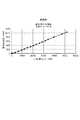
具体的には、図1〜図3において、レーザー媒質であるファイバー19は、フッ化物ファイバーであり、ファイバー径が280μm、ファイバー長は17cmである。ファイバーコアに3000ppm のPrを添加している。ファイバー両端にはニッケル製フェルール31,32を装着している。フェルールの外径は2.5mmで長さ12mmである。フェルールの内径は282μmであり、ファイバーを挿入後樹脂接着剤で接着している。また、ファイバー19およびフェルール31,32は銅製のハウジング30によって支持固定されている。この構造にて、ファイバー19の励起側端面19aに波長638nmで高反射の誘電体多層膜コーティング、および、出射ミラー21に波長638nmで反射率67%の誘電体多層膜コーティングを施し、レーザー共振器を構成した。
Specifically, in FIGS. 1 to 3, the
フッ化物ファイバー、ニッケル、銅の熱伝導率はそれぞれ、0.898W/mK、91W/mK、403W/mKである。また、それぞれの熱膨張係数は、18.6×10-6/K、13.4×10-6/K、16.5×10-6/Kである。ニッケルおよび銅は、フッ化物ファイバーと近い熱膨張係数を有しながら、高い熱伝導率を有する。その結果、図6のように、波長442nmの励起半導体レーザー入力5.0Wに対して、ファイバーレーザー出力(波長638nm)1.0W、効率約20%を得て、また、出力は飽和しなかった。 The thermal conductivity of fluoride fiber, nickel and copper is 0.898W / mK, 91W / mK and 403W / mK, respectively. Further, each of the thermal expansion coefficient is 18.6 × 10 -6 /K,13.4×10 -6 /K,16.5×10 -6 / K. Nickel and copper have a high thermal conductivity while having a coefficient of thermal expansion close to that of fluoride fiber. As a result, as shown in FIG. 6, a fiber laser output (wavelength 638 nm) of 1.0 W and an efficiency of about 20% were obtained with respect to an excitation semiconductor laser input of 5.0 W having a wavelength of 442 nm, and the output was not saturated.
事前検討例のように、フェルールにジルコニア材料、ハウジングにアルミニウム材料を用いた構造では、励起半導体レーザー入力2.5Wに対してファイバーレーザー出力0.425Wでレーザー出力は飽和し、それ以上の出力は得られなかった。これは、ジルコニア製フェルールの熱伝導性が低いためファイバーに熱が蓄積し、温度が上昇したため励起半導体レーザーの波長に対する吸収係数の低下、ファイバー材料の誘導放出断面積の低下、伝搬損失の増加が原因である。これに対し、本実施例では、高熱伝導率とファイバー材料に近い熱膨張係数とを有するフェルールおよびハウジングに置き換えることにより、レーザー出力の増大および効率の改善が図られた。 In the structure using zirconia material for the ferrule and aluminum material for the housing as in the preliminary study example, the laser output is saturated with the fiber laser output of 0.425W for the excitation semiconductor laser input of 2.5W, and more output can be obtained. There wasn't. This is because heat is accumulated in the fiber due to the low thermal conductivity of the zirconia ferrule, and the temperature rises, resulting in a decrease in the absorption coefficient for the wavelength of the excited semiconductor laser, a decrease in the stimulated emission cross-sectional area of the fiber material, and an increase in propagation loss. Responsible. On the other hand, in this embodiment, the laser output was increased and the efficiency was improved by replacing the ferrule and the housing having a high thermal conductivity and a coefficient of thermal expansion close to that of the fiber material.
以上のように本発明を実施するための形態および実施例について説明したが、本発明はこれらに限定されるものではなく、本発明の技術的思想の範囲内で各種の変形が可能である。たとえば、図1のファイバーレーザー装置の構成は、一例であって、他の構成であってもよいことはもちろんである。 Although the embodiments and examples for carrying out the present invention have been described above, the present invention is not limited to these, and various modifications can be made within the scope of the technical idea of the present invention. For example, the configuration of the fiber laser device of FIG. 1 is an example, and it goes without saying that other configurations may be used.
また、フェルールおよびハウジングを構成する材料として、熱膨張係数がファイバーの熱膨張係数に近似し、たとえば90W/mK以上の高熱伝導率を有するものであれば、他の材料も使用可能である。 Further, as a material constituting the ferrule and the housing, other materials can be used as long as the coefficient of thermal expansion is close to the coefficient of thermal expansion of the fiber and has a high thermal conductivity of, for example, 90 W / mK or more.
本発明のファイバーレーザー装置によれば、ファイバー短尺化により生じるファイバーの熱蓄積に起因する問題を回避できるので、社会的な要請の強い小型コンパクトな装置構成を実現し提供できる。 According to the fiber laser apparatus of the present invention, since the problem caused by the heat accumulation of the fiber caused by the shortening of the fiber length can be avoided, it is possible to realize and provide a compact and compact apparatus configuration with strong social demand.
10 ファイバーレーザー装置
11,11A 半導体レーザー
19 ファイバー
30 ハウジング
30a 上部
30b 下部
30c,30d 側板
31,32 フェルール
10
Claims (6)
前記ファイバーの端部にはフェルールが挿入され、
前記ファイバーを収容し前記フェルールで支持するハウジングを備え、
前記ハウジングおよび前記フェルールはそれぞれ、前記ファイバーの素材の熱膨張係数に近似した材料から構成され、前記材料の熱膨張係数Aと前記ファイバーの素材の熱膨張係数Bとの差(A−B)は、-8.6×10 -6 〜11.4×10 -6 /Kの範囲内にあるファイバーレーザー装置。 A fiber laser device that uses a short fiber with a length of 300 mm or less to which an active element is added.
A ferrule is inserted at the end of the fiber
A housing that houses the fiber and is supported by the ferrule.
Each of said housing and the ferrule is composed of wood charge approximating the thermal expansion coefficient of the material of the fiber, the difference between the material of the thermal expansion coefficient B of the thermal expansion coefficient A of the material fiber (A-B ) is, -8.6 × 10 -6 ~11.4 × 10 -6 / K range near Ru fiber laser device.
前記ファイバーの端部にはフェルールが挿入され、
前記ファイバーを収容し前記フェルールで支持するハウジングを備え、
前記ハウジングおよび前記フェルールはそれぞれ、10×10-6〜30×10-6/Kの範囲内の熱膨張係数を有する材料から構成され、前記ファイバーの素材の熱膨張係数は前記材料の熱膨張係数と近似するように前記範囲内にあるファイバーレーザー装置。 A fiber laser device that uses a short fiber with a length of 300 mm or less to which an active element is added.
A ferrule is inserted at the end of the fiber
A housing that houses the fiber and is supported by the ferrule.
The housing and the ferrule are each composed of a material having a coefficient of thermal expansion in the range of 10 × 10 -6 to 30 × 10 -6 / K, and the coefficient of thermal expansion of the material of the fiber is the coefficient of thermal expansion of the material. the range near to approximate the Ru fiber laser device.
Priority Applications (5)
| Application Number | Priority Date | Filing Date | Title |
|---|---|---|---|
| JP2019138108A JP6836043B2 (en) | 2019-07-26 | 2019-07-26 | Fiber laser device |
| CN202080045724.1A CN114008872A (en) | 2019-07-26 | 2020-07-20 | Fiber laser device |
| PCT/JP2020/027994 WO2021020188A1 (en) | 2019-07-26 | 2020-07-20 | Fibre laser device |
| EP20848206.7A EP4007089A4 (en) | 2019-07-26 | 2020-07-20 | Fibre laser device |
| US17/644,208 US11621535B2 (en) | 2019-07-26 | 2021-12-14 | Fiber laser apparatus |
Applications Claiming Priority (1)
| Application Number | Priority Date | Filing Date | Title |
|---|---|---|---|
| JP2019138108A JP6836043B2 (en) | 2019-07-26 | 2019-07-26 | Fiber laser device |
Publications (2)
| Publication Number | Publication Date |
|---|---|
| JP2021022654A JP2021022654A (en) | 2021-02-18 |
| JP6836043B2 true JP6836043B2 (en) | 2021-02-24 |
Family
ID=74229046
Family Applications (1)
| Application Number | Title | Priority Date | Filing Date |
|---|---|---|---|
| JP2019138108A Active JP6836043B2 (en) | 2019-07-26 | 2019-07-26 | Fiber laser device |
Country Status (5)
| Country | Link |
|---|---|
| US (1) | US11621535B2 (en) |
| EP (1) | EP4007089A4 (en) |
| JP (1) | JP6836043B2 (en) |
| CN (1) | CN114008872A (en) |
| WO (1) | WO2021020188A1 (en) |
Family Cites Families (22)
| Publication number | Priority date | Publication date | Assignee | Title |
|---|---|---|---|---|
| JP3920384B2 (en) | 1996-10-31 | 2007-05-30 | 憲一 植田 | Optical fiber laser equipment |
| US6263143B1 (en) * | 1998-10-15 | 2001-07-17 | Lucent Technologies Inc. | Package housing for laser module wound on a spool |
| EP1151337A1 (en) * | 1998-12-02 | 2001-11-07 | Corning Incorporated | A detachable plug-in pump card assembly |
| JP2002022972A (en) * | 2000-07-05 | 2002-01-23 | Sumitomo Electric Ind Ltd | Optical part |
| JP2004214325A (en) * | 2002-12-27 | 2004-07-29 | Toshiba Corp | Optical fiber heat sink and manufacturing method thereof |
| ATE488891T1 (en) * | 2004-06-30 | 2010-12-15 | Pgt Photonics Spa | TUNABLE LASER WITH THERMALLY CONTROLLED EXTERNAL RESONATOR |
| CA2533674A1 (en) * | 2006-01-23 | 2007-07-23 | Itf Technologies Optiques Inc./Itf Optical Technologies Inc. | Optical fiber component package for high power dissipation |
| JP2009116076A (en) * | 2007-11-07 | 2009-05-28 | Mitsubishi Electric Corp | Optical fiber fused part holding structure |
| JP2011525706A (en) * | 2008-06-25 | 2011-09-22 | コラクティヴ ハイ−テック インコーポレイティド | Energy dissipation package for high power optical fiber components |
| JP2010141283A (en) * | 2008-07-08 | 2010-06-24 | Central Glass Co Ltd | Wide-band wavelength-variable laser device |
| JP5308175B2 (en) * | 2009-02-03 | 2013-10-09 | 三星ダイヤモンド工業株式会社 | Optical fiber cooling equipment |
| JP2010224303A (en) | 2009-03-24 | 2010-10-07 | Nissei Electric Co Ltd | Terminal processed optical fiber |
| US9083140B2 (en) * | 2011-03-10 | 2015-07-14 | Coherent, Inc. | High-power CW fiber-laser |
| EP2715887A4 (en) * | 2011-06-03 | 2016-11-23 | Foro Energy Inc | Rugged passively cooled high power laser fiber optic connectors and methods of use |
| JP5588534B1 (en) * | 2013-03-28 | 2014-09-10 | 三星ダイヤモンド工業株式会社 | Optical fiber and laser oscillator using the same |
| JP2014199863A (en) * | 2013-03-29 | 2014-10-23 | ウシオ電機株式会社 | Fiber laser light source device |
| JP2015018984A (en) * | 2013-07-12 | 2015-01-29 | ウシオ電機株式会社 | Fiber laser light source device |
| JP2015065189A (en) * | 2013-09-24 | 2015-04-09 | ウシオ電機株式会社 | Fiber laser light source device |
| JP2015179761A (en) * | 2014-03-19 | 2015-10-08 | ウシオ電機株式会社 | fiber laser device |
| US9667025B2 (en) * | 2015-04-06 | 2017-05-30 | Bae Systems Information And Electronic Systems Integration Inc. | System and method for increasing power emitted from a fiber laser |
| DE102015013689A1 (en) * | 2015-10-21 | 2017-04-27 | Trumpf Laser Gmbh | Fiber support unit and fiber receiving element |
| JP6968110B2 (en) | 2017-02-10 | 2021-11-17 | 富士フイルム株式会社 | Optical connector and photoacoustic wave generator |
-
2019
- 2019-07-26 JP JP2019138108A patent/JP6836043B2/en active Active
-
2020
- 2020-07-20 WO PCT/JP2020/027994 patent/WO2021020188A1/en unknown
- 2020-07-20 EP EP20848206.7A patent/EP4007089A4/en active Pending
- 2020-07-20 CN CN202080045724.1A patent/CN114008872A/en active Pending
-
2021
- 2021-12-14 US US17/644,208 patent/US11621535B2/en active Active
Also Published As
| Publication number | Publication date |
|---|---|
| EP4007089A4 (en) | 2023-08-30 |
| US11621535B2 (en) | 2023-04-04 |
| EP4007089A1 (en) | 2022-06-01 |
| JP2021022654A (en) | 2021-02-18 |
| CN114008872A (en) | 2022-02-01 |
| WO2021020188A1 (en) | 2021-02-04 |
| US20220109280A1 (en) | 2022-04-07 |
Similar Documents
| Publication | Publication Date | Title |
|---|---|---|
| EP0953220B1 (en) | Optically transparent heat sink for longitudinally cooling an element in a laser | |
| US10367324B2 (en) | Laser component | |
| US6667999B2 (en) | Cooling of high power laser systems | |
| US20050244101A1 (en) | End face structure of optical fiber, optical fiber laser, and laser processing apparatus | |
| US7729392B2 (en) | Monoblock laser with reflective substrate | |
| WO2000008727A1 (en) | Solid state laser with longitudinal cooling | |
| JP5156385B2 (en) | Laser light source device and image display device | |
| JP6836043B2 (en) | Fiber laser device | |
| JP2015065189A (en) | Fiber laser light source device | |
| US6628692B2 (en) | Solid-state laser device and solid-state laser amplifier provided therewith | |
| JP2007299962A (en) | Thin disk laser device | |
| JP2004296671A (en) | Solid-state laser device | |
| US20220385025A1 (en) | Ultraviolet laser apparatus | |
| JP2000124533A (en) | Solid laser | |
| JPWO2006098313A1 (en) | Optical amplifier and laser device | |
| WO2015005107A1 (en) | Fiber laser light source device | |
| JPH07211980A (en) | Optical fiber amplifier | |
| JP2010056265A (en) | Laser light source, two-dimensional image display device using laser light source, liquid crystal display, and medical laser light source device | |
| JP2009212184A (en) | Fiber laser device | |
| JP2007123594A (en) | Optical-fiber optical amplifier and optical-fiber laser apparatus using same | |
| WO2020241363A1 (en) | Optical fiber device | |
| JPH11284257A (en) | Semiconductor laser excited solid laser device | |
| WO2000022702A1 (en) | Light amplifier, light amplification apparatus, and light amplification method | |
| JP2004325550A (en) | Light converging mechanism, semiconductor laser device and optically excited solid laser | |
| JP2001044540A (en) | Laser light generating device and optical signal amplifier |
Legal Events
| Date | Code | Title | Description |
|---|---|---|---|
| A521 | Request for written amendment filed |
Free format text: JAPANESE INTERMEDIATE CODE: A523 Effective date: 20190827 |
|
| A621 | Written request for application examination |
Free format text: JAPANESE INTERMEDIATE CODE: A621 Effective date: 20191004 |
|
| A131 | Notification of reasons for refusal |
Free format text: JAPANESE INTERMEDIATE CODE: A131 Effective date: 20200929 |
|
| A521 | Request for written amendment filed |
Free format text: JAPANESE INTERMEDIATE CODE: A523 Effective date: 20201124 |
|
| TRDD | Decision of grant or rejection written | ||
| A01 | Written decision to grant a patent or to grant a registration (utility model) |
Free format text: JAPANESE INTERMEDIATE CODE: A01 Effective date: 20201222 |
|
| A61 | First payment of annual fees (during grant procedure) |
Free format text: JAPANESE INTERMEDIATE CODE: A61 Effective date: 20210105 |
|
| R150 | Certificate of patent or registration of utility model |
Ref document number: 6836043 Country of ref document: JP Free format text: JAPANESE INTERMEDIATE CODE: R150 |
|
| S531 | Written request for registration of change of domicile |
Free format text: JAPANESE INTERMEDIATE CODE: R313531 |
|
| R350 | Written notification of registration of transfer |
Free format text: JAPANESE INTERMEDIATE CODE: R350 |
|
| R250 | Receipt of annual fees |
Free format text: JAPANESE INTERMEDIATE CODE: R250 |