EP3196973A1 - Traktionsbatterie für flurförderzeug - Google Patents
Traktionsbatterie für flurförderzeug Download PDFInfo
- Publication number
- EP3196973A1 EP3196973A1 EP17151543.0A EP17151543A EP3196973A1 EP 3196973 A1 EP3196973 A1 EP 3196973A1 EP 17151543 A EP17151543 A EP 17151543A EP 3196973 A1 EP3196973 A1 EP 3196973A1
- Authority
- EP
- European Patent Office
- Prior art keywords
- traction battery
- battery
- traction
- air
- battery according
- Prior art date
- Legal status (The legal status is an assumption and is not a legal conclusion. Google has not performed a legal analysis and makes no representation as to the accuracy of the status listed.)
- Granted
Links
Images
Classifications
-
- H—ELECTRICITY
- H01—ELECTRIC ELEMENTS
- H01M—PROCESSES OR MEANS, e.g. BATTERIES, FOR THE DIRECT CONVERSION OF CHEMICAL ENERGY INTO ELECTRICAL ENERGY
- H01M50/00—Constructional details or processes of manufacture of the non-active parts of electrochemical cells other than fuel cells, e.g. hybrid cells
- H01M50/20—Mountings; Secondary casings or frames; Racks, modules or packs; Suspension devices; Shock absorbers; Transport or carrying devices; Holders
- H01M50/249—Mountings; Secondary casings or frames; Racks, modules or packs; Suspension devices; Shock absorbers; Transport or carrying devices; Holders specially adapted for aircraft or vehicles, e.g. cars or trains
-
- H—ELECTRICITY
- H01—ELECTRIC ELEMENTS
- H01M—PROCESSES OR MEANS, e.g. BATTERIES, FOR THE DIRECT CONVERSION OF CHEMICAL ENERGY INTO ELECTRICAL ENERGY
- H01M10/00—Secondary cells; Manufacture thereof
- H01M10/42—Methods or arrangements for servicing or maintenance of secondary cells or secondary half-cells
- H01M10/48—Accumulators combined with arrangements for measuring, testing or indicating the condition of cells, e.g. the level or density of the electrolyte
- H01M10/486—Accumulators combined with arrangements for measuring, testing or indicating the condition of cells, e.g. the level or density of the electrolyte for measuring temperature
-
- H—ELECTRICITY
- H01—ELECTRIC ELEMENTS
- H01M—PROCESSES OR MEANS, e.g. BATTERIES, FOR THE DIRECT CONVERSION OF CHEMICAL ENERGY INTO ELECTRICAL ENERGY
- H01M10/00—Secondary cells; Manufacture thereof
- H01M10/42—Methods or arrangements for servicing or maintenance of secondary cells or secondary half-cells
- H01M10/48—Accumulators combined with arrangements for measuring, testing or indicating the condition of cells, e.g. the level or density of the electrolyte
- H01M10/488—Cells or batteries combined with indicating means for external visualization of the condition, e.g. by change of colour or of light density
-
- H—ELECTRICITY
- H01—ELECTRIC ELEMENTS
- H01M—PROCESSES OR MEANS, e.g. BATTERIES, FOR THE DIRECT CONVERSION OF CHEMICAL ENERGY INTO ELECTRICAL ENERGY
- H01M50/00—Constructional details or processes of manufacture of the non-active parts of electrochemical cells other than fuel cells, e.g. hybrid cells
- H01M50/20—Mountings; Secondary casings or frames; Racks, modules or packs; Suspension devices; Shock absorbers; Transport or carrying devices; Holders
- H01M50/204—Racks, modules or packs for multiple batteries or multiple cells
- H01M50/207—Racks, modules or packs for multiple batteries or multiple cells characterised by their shape
- H01M50/209—Racks, modules or packs for multiple batteries or multiple cells characterised by their shape adapted for prismatic or rectangular cells
-
- H—ELECTRICITY
- H01—ELECTRIC ELEMENTS
- H01M—PROCESSES OR MEANS, e.g. BATTERIES, FOR THE DIRECT CONVERSION OF CHEMICAL ENERGY INTO ELECTRICAL ENERGY
- H01M50/00—Constructional details or processes of manufacture of the non-active parts of electrochemical cells other than fuel cells, e.g. hybrid cells
- H01M50/20—Mountings; Secondary casings or frames; Racks, modules or packs; Suspension devices; Shock absorbers; Transport or carrying devices; Holders
- H01M50/233—Mountings; Secondary casings or frames; Racks, modules or packs; Suspension devices; Shock absorbers; Transport or carrying devices; Holders characterised by physical properties of casings or racks, e.g. dimensions
- H01M50/24—Mountings; Secondary casings or frames; Racks, modules or packs; Suspension devices; Shock absorbers; Transport or carrying devices; Holders characterised by physical properties of casings or racks, e.g. dimensions adapted for protecting batteries from their environment, e.g. from corrosion
-
- H—ELECTRICITY
- H01—ELECTRIC ELEMENTS
- H01M—PROCESSES OR MEANS, e.g. BATTERIES, FOR THE DIRECT CONVERSION OF CHEMICAL ENERGY INTO ELECTRICAL ENERGY
- H01M2220/00—Batteries for particular applications
- H01M2220/20—Batteries in motive systems, e.g. vehicle, ship, plane
-
- Y—GENERAL TAGGING OF NEW TECHNOLOGICAL DEVELOPMENTS; GENERAL TAGGING OF CROSS-SECTIONAL TECHNOLOGIES SPANNING OVER SEVERAL SECTIONS OF THE IPC; TECHNICAL SUBJECTS COVERED BY FORMER USPC CROSS-REFERENCE ART COLLECTIONS [XRACs] AND DIGESTS
- Y02—TECHNOLOGIES OR APPLICATIONS FOR MITIGATION OR ADAPTATION AGAINST CLIMATE CHANGE
- Y02E—REDUCTION OF GREENHOUSE GAS [GHG] EMISSIONS, RELATED TO ENERGY GENERATION, TRANSMISSION OR DISTRIBUTION
- Y02E60/00—Enabling technologies; Technologies with a potential or indirect contribution to GHG emissions mitigation
- Y02E60/10—Energy storage using batteries
Definitions
- the invention relates to a traction battery for a truck.
- the invention relates to a traction battery for a truck with a battery tray, a plurality of battery cells and a cooling device in the form of at least partially covering the top of the battery cells air duct with at least one air inlet opening for guiding a cooling air flow.
- traction batteries are used, which are usually used as interchangeable batteries in a battery compartment and, once they are discharged, can be replaced with a supercharged traction battery.
- these traction batteries are designed as a lead-acid battery.
- a lead gel technology is used in which an electrolyte of the battery cells chemically bound has a gel-like consistency.
- Such traction batteries are constructed so that multiple connected in series, standardized battery cells are arranged in a battery tray and a required voltage is achieved by the series connection.
- the battery tray can be transported with appropriate means of transport, such as another forklift or truck, and protects the battery cells from damage.
- traction batteries with large capacity and design as a lead-acid battery it is then often no longer possible, as usual eight or more hours per day to use the traction battery continuously, but it must be provided longer Auskühlphasen, so that not impermissibly high temperatures of the cells can be achieved.
- An operator can often detect the state of charge of a traction battery by means of an indicator in the industrial truck. Likewise, the state of charge can be detected when the traction battery is connected to a charger and this has a display for both external charging of the traction battery, but also if they are left in the truck loaded.
- Cooling devices for cooling the traction battery are known in the prior art.
- a known variant is to provide cooling by an air flow, which is passed in a battery compartment of the truck over the traction battery away. It can be announced ambient air of the truck and passed through the traction battery. For this, however, the truck must be set up accordingly. It is therefore also known to provide on the traction battery itself fan and air ducts that suck air from the battery compartment itself. In order to avoid a thermal short circuit, is sucked in the heated blown air again, air ducts are known in the art, also referred to as intake.
- air ducts By means of these air ducts, suction of air not heated by the truck can take place deliberately, for example from side areas or areas which have relatively large opening cross-sections to the surroundings, for example in the region of a battery compartment door.
- flat, horizontally arranged elements such as a horizontal plate or a plastic surface, a shield against the air heated by the battery, which rises, is found above and could lead to a thermal short circuit.
- air ducts may also provide weather protection against moisture for sensitive elements, such as a control device of the battery.
- Such, on the traction battery in a battery tray top air duct is from the DE 10 2014 106 647 A1 discloses a traction battery of a truck, in which a Batterietrogs covering hood is provided which has at least one air inlet opening and at least one air outlet opening to thereby allow a cooling air duct between the hood of the top of the battery cells.
- the present invention has for its object to provide a traction battery for a truck available, which avoids the disadvantages mentioned above and with the gentle treatment of the traction battery and an extension of the life is possible.
- the object is achieved in that in a traction battery for a truck with a battery tray, a plurality of battery cells and a cooling device in the form of at least partially covering the top of the battery cells air duct cover with at least one air inlet opening for guiding a cooling air flow, an optical display on the Air duct is provided which displays the measured values of at least one temperature sensor arranged in the interior of the traction battery between and / or on the battery cells.
- the at least one temperature sensor is arranged, for example, as possible in the core of the battery trough or in the middle of the battery trough. To improve the detection, several temperature sensors can be distributed. In this area, the heat dissipation is the worst and can cause the highest temperatures.
- the display allows the operator to detect the thermal condition of the traction battery and to decide whether the traction battery can be used, charged or needs a cooling break. With several available, charged traction batteries, one with the lowest temperature can be selected. This can extend the life of the traction battery. By integrating the display in the air duct hood, this can also be accommodated particularly advantageous in terms of space become.
- the air duct cover is usually designed so that it is located within the battery contour or within the space below the upper edge of the battery trough and thus is protected in the handling of the traction battery from mechanical damage.
- an opening upwards which can be passed through this air inlet opening of the air flow to the top of the battery, without it immediately comes to a circulation and a thermal short circuit.
- the visual display can display different colors.
- the display consists of three lights, preferably LED, with different colors, especially in a red, yellow and green in a light-yellow arrangement.
- the display may consist of a lamp that can light up in several colors, preferably an LED.
- the display can also be combined with other electronic components and control units, for example a battery control, or other electronics associated with the battery or the air duct, and integrated into them.
- other electronic components and control units for example a battery control, or other electronics associated with the battery or the air duct, and integrated into them.
- the visual display is a bar graph.
- the display can also be supplemented with symbols or pictograms. It is also conceivable that a light indicator or LED by flashing and in particular the flashing frequency illustrates the temperature value.
- the optical display is arranged on the air duct cover, that with an open battery door and / or through a recess of the battery door, this can be read when the traction battery is inserted into an industrial truck.
- At least one fan for generating the air flow is provided.
- the fan can be designed as a fixed part with the air duct hood part, but also be integrated into the battery tray.
- a controller may be provided which controls the fan.
- the fan is temperature-dependent controlled by the temperature sensor.
- the fan can be controlled via a wireless or wired signal connection from a charger and / or the truck.
- the air duct cover may have an air filter for the cooling air.
- a resulting from a constant flow of cooling air pollution can be avoided. It is also possible to provide a targeted turbulence in the air duct by the shaping. This prevents laminar flow and provides better cooling. Likewise, a quantity distribution of the air flow can be done by lamellae. Finally, it is also conceivable to achieve a reduction of the noise emissions by the design of the air duct cover.
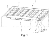
- the traction battery 1 consists of a battery tray 2, in which a plurality of battery cells 3 are arranged. On one side of the battery trough 2, an air guide hood 4 is arranged, which covers the upper side of the battery cells 3 in an edge region. An air inlet opening 5 is arranged on the side of the battery trough and cooling air can be passed through this under the air duct cover. On one side of the air duct 4, an integrated electronics 6 is arranged, are controlled via the three lights 7 in the traffic light colors red, yellow and green as optical display 11.
- a temperature sensor which is arranged between the battery cells in the center of the battery trough 2 controls the electronics 6 a green light 8 in the case of a permissible temperature range, a yellow light 9 at a critical temperature and a red light 10th at an inadmissibly high temperature.
Landscapes
- Chemical & Material Sciences (AREA)
- Chemical Kinetics & Catalysis (AREA)
- Electrochemistry (AREA)
- General Chemical & Material Sciences (AREA)
- Engineering & Computer Science (AREA)
- Manufacturing & Machinery (AREA)
- Aviation & Aerospace Engineering (AREA)
- Secondary Cells (AREA)
Abstract
Description
- Die Erfindung betrifft eine Traktionsbatterie für ein Flurförderzeug. Insbesondere betrifft die Erfindung eine Traktionsbatterie für ein Flurförderzeug mit einem Batterietrog, einer Mehrzahl von Batteriezellen und einer Kühleinrichtung in Form einer zumindest teilweise die Oberseite der Batteriezellen abdeckenden Luftführungshaube mit mindestens einer Lufteintrittsöffnung zur Führung eines Kühlluftstroms.
- Für den Betrieb von batterie-elektrisch angetriebenen Flurförderzeugen, wie etwa beispielsweise Gabelstaplern, kommen Traktionsbatterien zum Einsatz, die im Regelfall als austauschbare Batterien in ein Batteriefach eingesetzt und, sobald sie entladen sind, gegen eine aufgeladene Traktionsbatterie ersetzt werden können. Im Regelfall sind diese Traktionsbatterien als Blei-Säurebatterie ausgeführt. Häufig wird auch eine Blei-Geltechnologie eingesetzt, bei der ein Elektrolyt der Batteriezellen chemisch gebunden eine gelartige Konsistenz aufweist.
- Solche Traktionsbatterien sind so aufgebaut, dass mehrfach in Reihe verschaltete, standardisierte Batteriezellen in einem Batterietrog angeordnet sind und durch die Reihenschaltung eine geforderte Spannung erreicht wird. Der Batterietrog kann mit entsprechenden Transportmitteln, wie etwa einem weiteren Gabelstapler oder Flurförderzeug, transportiert werden und schützt die Batteriezellen vor Beschädigungen.
- Blei-Säurebatterien als Traktionsbatterien sind seit Jahrzehnten in vielen Einsatzbereichen bewährt. Nachteilig an diesem Stand der Technik ist jedoch, dass diese Batterien einen relativ hohen Innenwiderstand aufweisen, der beim Entladen wie auch beim Aufladen zu einer hohen Wärmeentwicklung führt. Bei Traktionsbatterien mit sehr großer Nennkapazität und einem entsprechend ungünstigen Verhältnis der Oberfläche zu dem dann zwangsläufig großen Volumen ergeben sich erhebliche Wärmekonzentrationen durch Abwärme. In der Praxis weisen die Traktionsbatterie dann auch ein sehr ungünstiges Abkühlverhalten auf aufgrund der des bereits genannten ungünstigen Verhältnisses von Oberfläche zu Volumen.
- Bei Traktionsbatterien mit großer Kapazität und Ausführung als Blei-Säurebatterie ist es dann oftmals nicht mehr möglich, wie üblich acht oder mehr Stunden pro Tag die Traktionsbatterie durchgehend einzusetzen, sondern es müssen längere Auskühlphasen vorgesehen werden, damit nicht unzulässig hohe Temperaturen der Zellen erreicht werden. Dabei kann ein Bediener den Ladezustand einer Traktionsbatterie oftmals durch eine Anzeige im Flurförderzeug erkennen. Ebenso kann der Ladezustand erkannt werden, wenn die Traktionsbatterie mit einem Ladegerät verbunden ist und dieses hierfür eine Anzeige aufweist, sowohl bei einem externen Laden der Traktionsbatterie, aber auch wenn diese im Flurförderzeug verbleiben geladen wird.
- Nachteilig ist jedoch, dass ein Bediener die interne Temperatur, insbesondere im Kernbereich einer Traktionsbatterie, nicht erkennen kann. Eine zu hohe Temperatur der Batteriezellen führt jedoch zu einer deutlichen Verringerung der Lebensdauer.
- Im Stand der Technik sind Kühlvorrichtungen zur Kühlung der Traktionsbatterie bekannt. Eine bekannte Variante ist eine Kühlung durch einen Luftstrom vorzusehen, der in einem Batteriefach des Flurförderzeugs über die Traktionsbatterie hinweg geleitet wird. Es kann Umgebungsluft des Flurförderzeugs angesagt und über die Traktionsbatterie geleitet werden. Hierfür muss jedoch das Flurförderzeug entsprechend eingerichtet sein. Es ist daher auch bekannt, an der Traktionsbatterie selbst Lüfter und Luftführungen vorzusehen, die Luft aus dem Batteriefach selbst ansaugen. Um dabei einen thermischen Kurzschluss zu vermeiden, bei dem erwärmte ausgeblasene Luft wieder angesaugt wird, sind im Stand der Technik Luftführungen bekannt, auch bezeichnet als Ansaugkasten. Durch diese Luftführungen kann gezielt eine Ansaugung von durch das Flurförderzeug nicht erwärmter Luft erfolgen, beispielsweise aus Seitenbereichen oder Bereichen, die relativ große Öffnungsquerschnitte zur Umgebung aufweisen, etwa im Bereich einer Batteriefachtür. Durch flächige, waagerecht angeordnete Elemente, etwa ein waagerechtes Blech oder eine Kunststofffläche , kann eine Abschirmung gegenüber der durch die Batterie erwärmten Luft erfolgen, die aufsteigt, sich oberhalb findet und zu einem thermischen Kurzschluss führen könnte. Zusätzlich können solche Luftführungen auch einen Wetterschutz gegen Feuchtigkeit für empfindliche Elemente bieten, beispielsweise eine Steuerungsvorrichtung der Batterie.
- Eine solche, auf die Traktionsbatterie in einem Batterietrog oben eingesetzte Luftführung ist aus der
DE 10 2014 106 647 A1 bekannt, die einen Traktionsbatterie eines Flurförderzeugs offenbart, bei der eine den Batterietrogs abdeckende Haube vorgesehen ist, die über mindestens eine Lufteintrittsöffnung und mindestens eine Luftluftaustrittsöffnung verfügt um dadurch eine Kühlluftführung zwischen der Haube der Oberseite der Batteriezellen zu ermöglichen. - Der vorliegenden Erfindung liegt die Aufgabe zugrunde, eine Traktionsbatterie für ein Flurförderzeug zur Verfügung zu stellen, die die oben genannten Nachteile vermeidet und mit der eine schonende Behandlung der Traktionsbatterie sowie eine Verlängerung der Lebensdauer ermöglicht wird.
- Diese Aufgabe wird durch eine Traktionsbatterie für ein Flurförderzeug mit den Merkmalen des unabhängigen Patentanspruchs 1 gelöst. Vorteilhafte Weiterbildungen der Erfindung sind in den Unteransprüchen angegeben.
- Die Aufgabe wird erfindungsgemäß dadurch gelöst, dass bei einer Traktionsbatterie für ein Flurförderzeug mit einem Batterietrog, einer Mehrzahl von Batteriezellen und einer Kühleinrichtung in Form einer zumindest teilweise die Oberseite der Batteriezellen abdeckenden Luftführungshaube mit mindestens einer Lufteintrittsöffnung zur Führung eines Kühlluftstroms, eine optische Anzeige an der Luftführungshaube vorgesehen ist, die die Messwerte mindestens eines im Inneren der Traktionsbatterie zwischen und/oder an den Batteriezellen angeordneten Temperatursensors anzeigt.
- Der mindestens eine Temperatursensor wird dabei beispielsweise möglichst im Kern des Batterietrogs bzw. in der Mitte des Batterietrogs angeordnet. Zur Verbesserung der Erfassung können auch mehrere Temperatursensoren verteilt angeordnet werden. In diesem Bereich ist die Wärmeableitung am schlechtesten und können die höchsten Temperaturen entstehen. Durch die Anzeige kann der Bediener den thermischen Zustand der Traktionsbatterie erkennen und entscheiden, ob die Traktionsbatterie eingesetzt, geladen werden kann, oder erst eine Abkühlpause benötigt. Bei mehreren zur Verfügung stehenden, geladenen Traktionsbatterien kann eine mit der niedrigsten Temperatur ausgesucht werden. Dadurch kann die Lebensdauer der Traktionsbatterie verlängert werden. Durch die Integration der Anzeige in die Luftführungshaube kann diese auch in Hinsicht auf die Platzverhältnisse besonders vorteilhaft untergebracht werden. Die Luftführungshaube ist im Regelfall so ausgeführt, dass diese innerhalb der Batteriekontur bzw. innerhalb des Raums unter der Oberkante des Batterietrogs sich befindet und somit bei der Handhabung der Traktionsbatterie vor mechanischen Beschädigungen geschützt ist. Dabei wird insbesondere durch die Luftführungshaube seitlich an dem Batterietrog eine Öffnung nach oben abgeschirmt, wobei über diese Lufteintrittsöffnung der Luftstrom auf die Oberseite der Batterie geleitet werden kann, ohne dass es sofort zu einer Umwälzung und einem thermischen Kurzschluss kommt.
- Die optische Anzeige kann verschiedene Farben anzeigen.
- Vorteilhaft besteht die Anzeige aus drei Leuchten, bevorzugt LED, mit verschiedenen Farben, insbesondere in einer ampelfarbigen Anordnung rot, gelb und grün.
- Eine solche Anordnung ist zweckmäßig, insbesondere ähnlich einer Ampel, da jeder Bediener diese intuitiv versteht. Die Zuordnung der Temperaturbereiche ist dann leicht verständlich, da grün einen zulässigen Bereich verdeutlicht, gelb einen kritischen und rot einen unzulässig hohen Temperaturbereich. Eine weitere denkbare Alternative wäre eine Anzeige von rot, rot/gelb, gelb, gelb/grün und grün, um eine weitere Ausdifferenzierung zu ermöglichen.
- Die Anzeige kann aus einer Leuchte besteht, die in mehreren Farben aufleuchten kann, bevorzugt einer LED.
- Grundsätzlich kann die Anzeige auch mit weiteren elektronischen Komponenten und Steuereinheiten, beispielsweise einer Batteriesteuerung, oder sonstigen der Batterie bzw. der Luftführungshaube zugeordneter Elektronik kombiniert werden und in diese integriert werden.
- Vorteilhaft ist die optische Anzeige eine Balkenanzeige.
- Die Anzeige kann auch mit Symbolen bzw. Piktogrammen ergänzt werden. Ebenso ist es denkbar, dass eine Leuchtanzeige bzw. LED durch Blinken und insbesondere die Blinkfrequenz den Temperaturwert verdeutlicht.
- In einer günstigen Ausgestaltung ist die optische Anzeige so an der Luftführungshaube angeordnet, dass bei einer geöffneten Batterietür und/oder durch eine Aussparung der Batterietür diese abgelesen werden kann, wenn die Traktionsbatterie in ein Flurförderzeug eingesetzt ist.
- In einer günstigen Ausgestaltung ist mindestens ein Lüfter zur Erzeugung des Luftstroms vorgesehen.
- Der Lüfter kann dabei als fest mit der Luftführungshaube verbundenes Teil ausgebildet, aber auch in den Batterietrog integriert sein. Zusätzlich kann eine Steuerung vorgesehen sein, die den Lüfter regelt.
- Vorteilhaft ist der Lüfter temperaturabhängig durch den Temperatursensor gesteuert ist.
- Vorteilhaft kann der Lüfter über eine drahtlose oder kabelgebundene Signalverbindung von einem Ladegerät und/oder dem Flurförderzeug gesteuert werden.
- Damit wird der Energieverbrauch des Lüfters minimiert und dieser nur eingesetzt, wenn dies erforderlich ist. Es ist natürlich auch denkbar, den Lüfter dauernd laufen zu lassen. Insbesondere aber kann auch eine temperaturabhängige Regelung dahingehend erfolgen, dass die Drehzahl und Luftfördermenge des Lüfters geregelt wird. Ganz allgemein kann auch eine drahtlose-oder kabelgebundene Signalverbindung zwischen einer Elektronik oder Steuerung der Traktionsbatterie und dem Flurförderzeug bestehen. Dies ermöglicht es beispielsweise, Hinweise und Handlungsanweisungen im Falle einer zu hohen Temperatur der Traktionsbatterie für einen Bediener auf einer Anzeigevorrichtung des Flurförderzeugs darzustellen. Eine solche Kommunikation kann über einen CAN-Bus ausgeführt sein. Es ist denkbar, abhängig von der Temperatur der Traktionsbatterie Maßnahmen zur Beschränkung von Fahrfunktionen und/oder Lasthandhabungsfunktionen vorzunehmen, um eine weitere Erwärmung durch den Entladestrom zu begrenzen.
- Die Luftführungshaube kann einen Luftfilter für die Kühlluft aufweisen.
- Eine sich durch einen beständigen Kühlluftstrom ergebende Verschmutzungsgefahr kann dadurch vermieden werden. Es ist auch möglich, bei der Luftführungshaube eine gezielte Verwirbelung vorzusehen durch die Formgebung. Dies verhindert eine laminare Strömung und bewirkt eine bessere Kühlung. Ebenso kann eine Mengenverteilung des Luftstroms durch Lamellen erfolgen. Schließlich ist es auch denkbar, durch die Ausgestaltung der Luftführungshaube eine Reduzierung der Schallemissionen zu erreichen.
- Weitere Vorteile und Einzelheiten der Erfindung werden anhand des in der schematischen Figur dargestellten Ausführungsbeispiels näher erläutert. Die Traktionsbatterie 1 besteht aus einem Batterietrog 2, in dem eine Mehrzahl von Batteriezellen 3 angeordnet sind. An einer Seite des Batterietrogs 2 ist eine Luftführungshaube 4 angeordnet, die die Oberseite der Batteriezellen 3 in einem Randbereich überdeckt. Eine Lufteintrittsöffnung 5 ist an der Seite des Batterietrogs angeordnet und Kühlluft kann durch diese unter die Luftführungshaube geleitet werden. An einer Seite der Luftführungshaube 4 ist eine integrierte Elektronik 6 angeordnet, über die drei Leuchten 7 in den Ampelfarben rot, gelb und grün als optische Anzeige 11 angesteuert werden. Abhängig von dem Signal eines hier nicht dargestellten Temperatursensors, der zwischen den Batteriezellen im Zentrum des Batterietrogs 2 angeordnet ist, steuert die Elektronik 6 eine grüne Leuchte 8 an im Fall eines zulässigen Temperaturbereichs, eine gelbe Leuchte 9 bei einer kritischen Temperatur und eine rote Leuchte 10 bei einer unzulässig hohen Temperatur.
Claims (10)
- Traktionsbatterie für ein Flurförderzeug mit einem Batterietrog (2), einer Mehrzahl von Batteriezellen (3) und einer Kühleinrichtung in Form einer zumindest teilweise die Oberseite der Batteriezellen abdeckenden Luftführungshaube (4) mit mindestens einer Lufteintrittsöffnung (5) zur Führung eines Kühlluftstroms, dadurch gekennzeichnet,
dass eine optische Anzeige (11) an der Luftführungshaube (4) vorgesehen ist, die die Messwerte mindestens eines im Inneren der Traktionsbatterie (1) zwischen und/oder an den Batteriezellen (3) angeordneten Temperatursensors anzeigt. - Traktionsbatterie nach Anspruch 1,
dadurch gekennzeichnet,
dass die optische Anzeige (11) verschiedene Farben anzeigen kann. - Traktionsbatterie nach Anspruch 2,
dadurch gekennzeichnet,
dass die Anzeige (11) aus drei Leuchten (7), bevorzugt LED, mit verschiedenen Farben besteht, insbesondere in einer ampelfarbigen Anordnung rot, gelb und grün. - Traktionsbatterie nach Anspruch 2,
dadurch gekennzeichnet,
dass die Anzeige (11) aus einer Leuchte (7) besteht, die in mehreren Farben aufleuchten kann, bevorzugt einer LED. - Traktionsbatterie nach einem der Ansprüche 1 bis 4,
dadurch gekennzeichnet,
dass die optische Anzeige (11) eine Balkenanzeige ist. - Traktionsbatterie nach einem der Ansprüche 1 bis 5,
dadurch gekennzeichnet,
dass die optische Anzeige (11) so an der Luftführungshaube (4) angeordnet ist, dass bei einer geöffneten Batterietür und/oder durch eine Aussparung der Batterietür diese abgelesen werden kann, wenn die Traktionsbatterie (1) in ein Flurförderzeug eingesetzt ist - Traktionsbatterie nach einem der Ansprüche 1 bis 6,
dadurch gekennzeichnet,
dass mindestens ein Lüfter zur Erzeugung eines Luftstroms vorgesehen ist. - Traktionsbatterie nach Anspruch 7,
dadurch gekennzeichnet,
dass der Lüfter temperaturabhängig durch den Temperatursensor gesteuert ist. - Traktionsbatterie nach Anspruch 7 oder 8,
dadurch gekennzeichnet,
dass der Lüfter über eine drahtlose oder kabelgebundene Signalverbindung von einem Ladegerät und/oder dem Flurförderzeug gesteuert werden kann. - Traktionsbatterie nach einem der Ansprüche 1 bis 9,
dadurch gekennzeichnet,
dass die Luftführungshaube (4) einen Luftfilter für die Kühlluft aufweist.
Applications Claiming Priority (1)
| Application Number | Priority Date | Filing Date | Title |
|---|---|---|---|
| DE102016100922.9A DE102016100922A1 (de) | 2016-01-20 | 2016-01-20 | Traktionsbatterie für Flurförderzeug |
Publications (2)
| Publication Number | Publication Date |
|---|---|
| EP3196973A1 true EP3196973A1 (de) | 2017-07-26 |
| EP3196973B1 EP3196973B1 (de) | 2022-12-21 |
Family
ID=58016519
Family Applications (1)
| Application Number | Title | Priority Date | Filing Date |
|---|---|---|---|
| EP17151543.0A Active EP3196973B1 (de) | 2016-01-20 | 2017-01-16 | Traktionsbatterie für flurförderzeug |
Country Status (2)
| Country | Link |
|---|---|
| EP (1) | EP3196973B1 (de) |
| DE (1) | DE102016100922A1 (de) |
Cited By (1)
| Publication number | Priority date | Publication date | Assignee | Title |
|---|---|---|---|---|
| CN117638367A (zh) * | 2023-11-30 | 2024-03-01 | 神河汽车有限公司 | 一种新能源商用车用蓄电池保护装置 |
Citations (3)
| Publication number | Priority date | Publication date | Assignee | Title |
|---|---|---|---|---|
| US20080118819A1 (en) * | 2006-11-17 | 2008-05-22 | Paul Gamboa | Modular battery system |
| CN104241706A (zh) * | 2014-04-02 | 2014-12-24 | 超威电源有限公司 | 智能铅酸蓄电池组 |
| DE102014106647A1 (de) | 2014-05-12 | 2015-11-12 | Linde Material Handling Gmbh | Batterieblock mit Kühlluftführung |
-
2016
- 2016-01-20 DE DE102016100922.9A patent/DE102016100922A1/de not_active Withdrawn
-
2017
- 2017-01-16 EP EP17151543.0A patent/EP3196973B1/de active Active
Patent Citations (3)
| Publication number | Priority date | Publication date | Assignee | Title |
|---|---|---|---|---|
| US20080118819A1 (en) * | 2006-11-17 | 2008-05-22 | Paul Gamboa | Modular battery system |
| CN104241706A (zh) * | 2014-04-02 | 2014-12-24 | 超威电源有限公司 | 智能铅酸蓄电池组 |
| DE102014106647A1 (de) | 2014-05-12 | 2015-11-12 | Linde Material Handling Gmbh | Batterieblock mit Kühlluftführung |
Cited By (1)
| Publication number | Priority date | Publication date | Assignee | Title |
|---|---|---|---|---|
| CN117638367A (zh) * | 2023-11-30 | 2024-03-01 | 神河汽车有限公司 | 一种新能源商用车用蓄电池保护装置 |
Also Published As
| Publication number | Publication date |
|---|---|
| EP3196973B1 (de) | 2022-12-21 |
| DE102016100922A1 (de) | 2017-07-20 |
Similar Documents
| Publication | Publication Date | Title |
|---|---|---|
| DE102011000353B4 (de) | Batterie | |
| DE102020202840A1 (de) | Stationäre Induktionsladevorrichtung zur drahtlosen Energieübertragung | |
| DE102008051085A1 (de) | Batterieanordnung | |
| DE112011103046T5 (de) | Brennstoffzellenmodul mit Wasser- und Wärmemanagementfunktion sowie Managementverfahren für das Brennstoffzellenmodul | |
| DE102010009732A1 (de) | Batterie für einen Kraftwagen | |
| EP2808976A1 (de) | Schaltungsanordnung für den Primärteil eines Systems zur kontaktlosen Energieübertragung, sowie Übertragerelement | |
| DE102004021280B3 (de) | Vorrichtung zur Kühlung von abwärmeerzeugenden elektrischen oder elektronischen Bauteilen und Verwendung der Vorrichtung | |
| DE112018002018T5 (de) | Ladegerät, das zum Laden eines Batteriepacks eines Kraftwerkzeuges konfiguriert ist | |
| DE102022122763A1 (de) | Fahrzeug-Ladedose und Fahrzeug | |
| DE102018219894A1 (de) | Batterieüberwachungsvorrichtung | |
| DE102016204720A1 (de) | Verfahren und Vorrichtung zum Kühlen eines Batteriemoduls mittels Fahrtwind | |
| EP3196973B1 (de) | Traktionsbatterie für flurförderzeug | |
| DE102013216104A1 (de) | Verfahren zum Homogenisieren der Temperaturverteilung in den Zellen einer Lithium-Ionen-Batterie für ein Kraftfahrzeug sowie Lithium-Ionen-Batterie für ein Kraftfahrzeug | |
| DE212016000134U1 (de) | Ladegerät | |
| EP2088012B1 (de) | Ladegerät für eine Batterie eines Fahrzeugs | |
| EP3168895A1 (de) | Traktionsbatterie für ein flurförderzeug | |
| AT15252U1 (de) | LED-Schaltungsanordnung und Verfahren zum Betreiben einer LED-Schaltungsanordnung | |
| EP1781075B1 (de) | Kühlvorrichtung für ein Kraftfahrzeug mit einem aus zwei Motoren bestehenden Antrieb | |
| DE102019120031A1 (de) | Kontrolleinrichtung | |
| DE102012019943B4 (de) | Verfahren und Vorrichtung zur Vermeidung oder Reduzierung von Betauungszuständen in oder an einer elektrischen Komponente | |
| DE102008034878A1 (de) | Batterie mit einer Wärmeleitplatte zum Temperieren der Batterie | |
| DE102005047387A1 (de) | Flurförderzeug, insbesondere Schubmaststapler mit einer seitlichen Wartungsöffnung | |
| DE102004032475B4 (de) | U-Boot-Überspannungsschutzeinrichtung | |
| EP3242824A1 (de) | Schienenfahrzeug mit traktionskühlanlage | |
| EP1737063B1 (de) | Energieversorgungseinrichtung für ein Flurförderzeug |
Legal Events
| Date | Code | Title | Description |
|---|---|---|---|
| PUAI | Public reference made under article 153(3) epc to a published international application that has entered the european phase |
Free format text: ORIGINAL CODE: 0009012 |
|
| STAA | Information on the status of an ep patent application or granted ep patent |
Free format text: STATUS: THE APPLICATION HAS BEEN PUBLISHED |
|
| AK | Designated contracting states |
Kind code of ref document: A1 Designated state(s): AL AT BE BG CH CY CZ DE DK EE ES FI FR GB GR HR HU IE IS IT LI LT LU LV MC MK MT NL NO PL PT RO RS SE SI SK SM TR |
|
| AX | Request for extension of the european patent |
Extension state: BA ME |
|
| STAA | Information on the status of an ep patent application or granted ep patent |
Free format text: STATUS: REQUEST FOR EXAMINATION WAS MADE |
|
| 17P | Request for examination filed |
Effective date: 20180123 |
|
| RBV | Designated contracting states (corrected) |
Designated state(s): AL AT BE BG CH CY CZ DE DK EE ES FI FR GB GR HR HU IE IS IT LI LT LU LV MC MK MT NL NO PL PT RO RS SE SI SK SM TR |
|
| STAA | Information on the status of an ep patent application or granted ep patent |
Free format text: STATUS: EXAMINATION IS IN PROGRESS |
|
| 17Q | First examination report despatched |
Effective date: 20210514 |
|
| RIC1 | Information provided on ipc code assigned before grant |
Ipc: H01M 50/204 20210101ALN20220531BHEP Ipc: H01M 10/48 20060101AFI20220531BHEP |
|
| GRAP | Despatch of communication of intention to grant a patent |
Free format text: ORIGINAL CODE: EPIDOSNIGR1 |
|
| STAA | Information on the status of an ep patent application or granted ep patent |
Free format text: STATUS: GRANT OF PATENT IS INTENDED |
|
| RIC1 | Information provided on ipc code assigned before grant |
Ipc: H01M 50/204 20210101ALN20220628BHEP Ipc: H01M 10/48 20060101AFI20220628BHEP |
|
| INTG | Intention to grant announced |
Effective date: 20220715 |
|
| GRAS | Grant fee paid |
Free format text: ORIGINAL CODE: EPIDOSNIGR3 |
|
| GRAA | (expected) grant |
Free format text: ORIGINAL CODE: 0009210 |
|
| STAA | Information on the status of an ep patent application or granted ep patent |
Free format text: STATUS: THE PATENT HAS BEEN GRANTED |
|
| AK | Designated contracting states |
Kind code of ref document: B1 Designated state(s): AL AT BE BG CH CY CZ DE DK EE ES FI FR GB GR HR HU IE IS IT LI LT LU LV MC MK MT NL NO PL PT RO RS SE SI SK SM TR |
|
| REG | Reference to a national code |
Ref country code: GB Ref legal event code: FG4D Free format text: NOT ENGLISH |
|
| REG | Reference to a national code |
Ref country code: CH Ref legal event code: EP |
|
| REG | Reference to a national code |
Ref country code: DE Ref legal event code: R096 Ref document number: 502017014228 Country of ref document: DE |
|
| REG | Reference to a national code |
Ref country code: AT Ref legal event code: REF Ref document number: 1539596 Country of ref document: AT Kind code of ref document: T Effective date: 20230115 |
|
| REG | Reference to a national code |
Ref country code: IE Ref legal event code: FG4D Free format text: LANGUAGE OF EP DOCUMENT: GERMAN |
|
| REG | Reference to a national code |
Ref country code: LT Ref legal event code: MG9D |
|
| REG | Reference to a national code |
Ref country code: NL Ref legal event code: MP Effective date: 20221221 |
|
| PG25 | Lapsed in a contracting state [announced via postgrant information from national office to epo] |
Ref country code: SE Free format text: LAPSE BECAUSE OF FAILURE TO SUBMIT A TRANSLATION OF THE DESCRIPTION OR TO PAY THE FEE WITHIN THE PRESCRIBED TIME-LIMIT Effective date: 20221221 Ref country code: NO Free format text: LAPSE BECAUSE OF FAILURE TO SUBMIT A TRANSLATION OF THE DESCRIPTION OR TO PAY THE FEE WITHIN THE PRESCRIBED TIME-LIMIT Effective date: 20230321 Ref country code: LT Free format text: LAPSE BECAUSE OF FAILURE TO SUBMIT A TRANSLATION OF THE DESCRIPTION OR TO PAY THE FEE WITHIN THE PRESCRIBED TIME-LIMIT Effective date: 20221221 Ref country code: FI Free format text: LAPSE BECAUSE OF FAILURE TO SUBMIT A TRANSLATION OF THE DESCRIPTION OR TO PAY THE FEE WITHIN THE PRESCRIBED TIME-LIMIT Effective date: 20221221 |
|
| PG25 | Lapsed in a contracting state [announced via postgrant information from national office to epo] |
Ref country code: RS Free format text: LAPSE BECAUSE OF FAILURE TO SUBMIT A TRANSLATION OF THE DESCRIPTION OR TO PAY THE FEE WITHIN THE PRESCRIBED TIME-LIMIT Effective date: 20221221 Ref country code: LV Free format text: LAPSE BECAUSE OF FAILURE TO SUBMIT A TRANSLATION OF THE DESCRIPTION OR TO PAY THE FEE WITHIN THE PRESCRIBED TIME-LIMIT Effective date: 20221221 Ref country code: HR Free format text: LAPSE BECAUSE OF FAILURE TO SUBMIT A TRANSLATION OF THE DESCRIPTION OR TO PAY THE FEE WITHIN THE PRESCRIBED TIME-LIMIT Effective date: 20221221 Ref country code: GR Free format text: LAPSE BECAUSE OF FAILURE TO SUBMIT A TRANSLATION OF THE DESCRIPTION OR TO PAY THE FEE WITHIN THE PRESCRIBED TIME-LIMIT Effective date: 20230322 |
|
| PG25 | Lapsed in a contracting state [announced via postgrant information from national office to epo] |
Ref country code: NL Free format text: LAPSE BECAUSE OF FAILURE TO SUBMIT A TRANSLATION OF THE DESCRIPTION OR TO PAY THE FEE WITHIN THE PRESCRIBED TIME-LIMIT Effective date: 20221221 |
|
| PG25 | Lapsed in a contracting state [announced via postgrant information from national office to epo] |
Ref country code: SM Free format text: LAPSE BECAUSE OF FAILURE TO SUBMIT A TRANSLATION OF THE DESCRIPTION OR TO PAY THE FEE WITHIN THE PRESCRIBED TIME-LIMIT Effective date: 20221221 Ref country code: RO Free format text: LAPSE BECAUSE OF FAILURE TO SUBMIT A TRANSLATION OF THE DESCRIPTION OR TO PAY THE FEE WITHIN THE PRESCRIBED TIME-LIMIT Effective date: 20221221 Ref country code: PT Free format text: LAPSE BECAUSE OF FAILURE TO SUBMIT A TRANSLATION OF THE DESCRIPTION OR TO PAY THE FEE WITHIN THE PRESCRIBED TIME-LIMIT Effective date: 20230421 Ref country code: ES Free format text: LAPSE BECAUSE OF FAILURE TO SUBMIT A TRANSLATION OF THE DESCRIPTION OR TO PAY THE FEE WITHIN THE PRESCRIBED TIME-LIMIT Effective date: 20221221 Ref country code: EE Free format text: LAPSE BECAUSE OF FAILURE TO SUBMIT A TRANSLATION OF THE DESCRIPTION OR TO PAY THE FEE WITHIN THE PRESCRIBED TIME-LIMIT Effective date: 20221221 Ref country code: CZ Free format text: LAPSE BECAUSE OF FAILURE TO SUBMIT A TRANSLATION OF THE DESCRIPTION OR TO PAY THE FEE WITHIN THE PRESCRIBED TIME-LIMIT Effective date: 20221221 |
|
| PG25 | Lapsed in a contracting state [announced via postgrant information from national office to epo] |
Ref country code: SK Free format text: LAPSE BECAUSE OF FAILURE TO SUBMIT A TRANSLATION OF THE DESCRIPTION OR TO PAY THE FEE WITHIN THE PRESCRIBED TIME-LIMIT Effective date: 20221221 Ref country code: PL Free format text: LAPSE BECAUSE OF FAILURE TO SUBMIT A TRANSLATION OF THE DESCRIPTION OR TO PAY THE FEE WITHIN THE PRESCRIBED TIME-LIMIT Effective date: 20221221 Ref country code: IS Free format text: LAPSE BECAUSE OF FAILURE TO SUBMIT A TRANSLATION OF THE DESCRIPTION OR TO PAY THE FEE WITHIN THE PRESCRIBED TIME-LIMIT Effective date: 20230421 Ref country code: AL Free format text: LAPSE BECAUSE OF FAILURE TO SUBMIT A TRANSLATION OF THE DESCRIPTION OR TO PAY THE FEE WITHIN THE PRESCRIBED TIME-LIMIT Effective date: 20221221 |
|
| REG | Reference to a national code |
Ref country code: CH Ref legal event code: PL |
|
| REG | Reference to a national code |
Ref country code: DE Ref legal event code: R097 Ref document number: 502017014228 Country of ref document: DE |
|
| PG25 | Lapsed in a contracting state [announced via postgrant information from national office to epo] |
Ref country code: MC Free format text: LAPSE BECAUSE OF FAILURE TO SUBMIT A TRANSLATION OF THE DESCRIPTION OR TO PAY THE FEE WITHIN THE PRESCRIBED TIME-LIMIT Effective date: 20221221 Ref country code: LU Free format text: LAPSE BECAUSE OF NON-PAYMENT OF DUE FEES Effective date: 20230116 |
|
| REG | Reference to a national code |
Ref country code: BE Ref legal event code: MM Effective date: 20230131 |
|
| PLBE | No opposition filed within time limit |
Free format text: ORIGINAL CODE: 0009261 |
|
| STAA | Information on the status of an ep patent application or granted ep patent |
Free format text: STATUS: NO OPPOSITION FILED WITHIN TIME LIMIT |
|
| PG25 | Lapsed in a contracting state [announced via postgrant information from national office to epo] |
Ref country code: LI Free format text: LAPSE BECAUSE OF NON-PAYMENT OF DUE FEES Effective date: 20230131 Ref country code: DK Free format text: LAPSE BECAUSE OF FAILURE TO SUBMIT A TRANSLATION OF THE DESCRIPTION OR TO PAY THE FEE WITHIN THE PRESCRIBED TIME-LIMIT Effective date: 20221221 Ref country code: CH Free format text: LAPSE BECAUSE OF NON-PAYMENT OF DUE FEES Effective date: 20230131 |
|
| 26N | No opposition filed |
Effective date: 20230922 |
|
| GBPC | Gb: european patent ceased through non-payment of renewal fee |
Effective date: 20230321 |
|
| PG25 | Lapsed in a contracting state [announced via postgrant information from national office to epo] |
Ref country code: BE Free format text: LAPSE BECAUSE OF NON-PAYMENT OF DUE FEES Effective date: 20230131 |
|
| PG25 | Lapsed in a contracting state [announced via postgrant information from national office to epo] |
Ref country code: GB Free format text: LAPSE BECAUSE OF NON-PAYMENT OF DUE FEES Effective date: 20230321 |
|
| PG25 | Lapsed in a contracting state [announced via postgrant information from national office to epo] |
Ref country code: SI Free format text: LAPSE BECAUSE OF FAILURE TO SUBMIT A TRANSLATION OF THE DESCRIPTION OR TO PAY THE FEE WITHIN THE PRESCRIBED TIME-LIMIT Effective date: 20221221 Ref country code: IE Free format text: LAPSE BECAUSE OF NON-PAYMENT OF DUE FEES Effective date: 20230116 Ref country code: GB Free format text: LAPSE BECAUSE OF NON-PAYMENT OF DUE FEES Effective date: 20230321 Ref country code: FR Free format text: LAPSE BECAUSE OF NON-PAYMENT OF DUE FEES Effective date: 20230221 |
|
| REG | Reference to a national code |
Ref country code: AT Ref legal event code: MM01 Ref document number: 1539596 Country of ref document: AT Kind code of ref document: T Effective date: 20230116 |
|
| PG25 | Lapsed in a contracting state [announced via postgrant information from national office to epo] |
Ref country code: AT Free format text: LAPSE BECAUSE OF NON-PAYMENT OF DUE FEES Effective date: 20230116 |
|
| PG25 | Lapsed in a contracting state [announced via postgrant information from national office to epo] |
Ref country code: AT Free format text: LAPSE BECAUSE OF NON-PAYMENT OF DUE FEES Effective date: 20230116 |
|
| PG25 | Lapsed in a contracting state [announced via postgrant information from national office to epo] |
Ref country code: IT Free format text: LAPSE BECAUSE OF FAILURE TO SUBMIT A TRANSLATION OF THE DESCRIPTION OR TO PAY THE FEE WITHIN THE PRESCRIBED TIME-LIMIT Effective date: 20221221 |
|
| PG25 | Lapsed in a contracting state [announced via postgrant information from national office to epo] |
Ref country code: BG Free format text: LAPSE BECAUSE OF FAILURE TO SUBMIT A TRANSLATION OF THE DESCRIPTION OR TO PAY THE FEE WITHIN THE PRESCRIBED TIME-LIMIT Effective date: 20221221 |
|
| PG25 | Lapsed in a contracting state [announced via postgrant information from national office to epo] |
Ref country code: BG Free format text: LAPSE BECAUSE OF FAILURE TO SUBMIT A TRANSLATION OF THE DESCRIPTION OR TO PAY THE FEE WITHIN THE PRESCRIBED TIME-LIMIT Effective date: 20221221 |
|
| PG25 | Lapsed in a contracting state [announced via postgrant information from national office to epo] |
Ref country code: CY Free format text: LAPSE BECAUSE OF FAILURE TO SUBMIT A TRANSLATION OF THE DESCRIPTION OR TO PAY THE FEE WITHIN THE PRESCRIBED TIME-LIMIT; INVALID AB INITIO Effective date: 20170116 |
|
| PG25 | Lapsed in a contracting state [announced via postgrant information from national office to epo] |
Ref country code: HU Free format text: LAPSE BECAUSE OF FAILURE TO SUBMIT A TRANSLATION OF THE DESCRIPTION OR TO PAY THE FEE WITHIN THE PRESCRIBED TIME-LIMIT; INVALID AB INITIO Effective date: 20170116 |
|
| PG25 | Lapsed in a contracting state [announced via postgrant information from national office to epo] |
Ref country code: TR Free format text: LAPSE BECAUSE OF FAILURE TO SUBMIT A TRANSLATION OF THE DESCRIPTION OR TO PAY THE FEE WITHIN THE PRESCRIBED TIME-LIMIT Effective date: 20221221 |
|
| PGFP | Annual fee paid to national office [announced via postgrant information from national office to epo] |
Ref country code: DE Payment date: 20260120 Year of fee payment: 10 |