EP3196481A1 - Centrifugal compressor - Google Patents
Centrifugal compressor Download PDFInfo
- Publication number
- EP3196481A1 EP3196481A1 EP15842413.5A EP15842413A EP3196481A1 EP 3196481 A1 EP3196481 A1 EP 3196481A1 EP 15842413 A EP15842413 A EP 15842413A EP 3196481 A1 EP3196481 A1 EP 3196481A1
- Authority
- EP
- European Patent Office
- Prior art keywords
- disposed
- annular portion
- injection holes
- cleaning liquid
- cleaning
- Prior art date
- Legal status (The legal status is an assumption and is not a legal conclusion. Google has not performed a legal analysis and makes no representation as to the accuracy of the status listed.)
- Withdrawn
Links
- 239000007788 liquid Substances 0.000 claims abstract description 176
- 238000004140 cleaning Methods 0.000 claims abstract description 143
- 238000002347 injection Methods 0.000 claims abstract description 136
- 239000007924 injection Substances 0.000 claims abstract description 136
- 238000011144 upstream manufacturing Methods 0.000 claims description 12
- 230000002093 peripheral effect Effects 0.000 claims description 6
- 239000012530 fluid Substances 0.000 description 26
- 239000002699 waste material Substances 0.000 description 3
- 239000000428 dust Substances 0.000 description 2
- 230000000694 effects Effects 0.000 description 2
- 238000001816 cooling Methods 0.000 description 1
- 230000002706 hydrostatic effect Effects 0.000 description 1
- 239000000463 material Substances 0.000 description 1
- 230000004048 modification Effects 0.000 description 1
- 238000012986 modification Methods 0.000 description 1
- 239000000243 solution Substances 0.000 description 1
Images


Classifications
-
- F—MECHANICAL ENGINEERING; LIGHTING; HEATING; WEAPONS; BLASTING
- F01—MACHINES OR ENGINES IN GENERAL; ENGINE PLANTS IN GENERAL; STEAM ENGINES
- F01D—NON-POSITIVE DISPLACEMENT MACHINES OR ENGINES, e.g. STEAM TURBINES
- F01D9/00—Stators
- F01D9/06—Fluid supply conduits to nozzles or the like
- F01D9/065—Fluid supply or removal conduits traversing the working fluid flow, e.g. for lubrication-, cooling-, or sealing fluids
-
- F—MECHANICAL ENGINEERING; LIGHTING; HEATING; WEAPONS; BLASTING
- F04—POSITIVE - DISPLACEMENT MACHINES FOR LIQUIDS; PUMPS FOR LIQUIDS OR ELASTIC FLUIDS
- F04D—NON-POSITIVE-DISPLACEMENT PUMPS
- F04D29/00—Details, component parts, or accessories
- F04D29/70—Suction grids; Strainers; Dust separation; Cleaning
- F04D29/701—Suction grids; Strainers; Dust separation; Cleaning especially adapted for elastic fluid pumps
- F04D29/705—Adding liquids
-
- B—PERFORMING OPERATIONS; TRANSPORTING
- B08—CLEANING
- B08B—CLEANING IN GENERAL; PREVENTION OF FOULING IN GENERAL
- B08B3/00—Cleaning by methods involving the use or presence of liquid or steam
- B08B3/02—Cleaning by the force of jets or sprays
-
- F—MECHANICAL ENGINEERING; LIGHTING; HEATING; WEAPONS; BLASTING
- F01—MACHINES OR ENGINES IN GENERAL; ENGINE PLANTS IN GENERAL; STEAM ENGINES
- F01D—NON-POSITIVE DISPLACEMENT MACHINES OR ENGINES, e.g. STEAM TURBINES
- F01D25/00—Component parts, details, or accessories, not provided for in, or of interest apart from, other groups
- F01D25/24—Casings; Casing parts, e.g. diaphragms, casing fastenings
-
- F—MECHANICAL ENGINEERING; LIGHTING; HEATING; WEAPONS; BLASTING
- F04—POSITIVE - DISPLACEMENT MACHINES FOR LIQUIDS; PUMPS FOR LIQUIDS OR ELASTIC FLUIDS
- F04D—NON-POSITIVE-DISPLACEMENT PUMPS
- F04D29/00—Details, component parts, or accessories
- F04D29/60—Mounting; Assembling; Disassembling
- F04D29/62—Mounting; Assembling; Disassembling of radial or helico-centrifugal pumps
-
- F—MECHANICAL ENGINEERING; LIGHTING; HEATING; WEAPONS; BLASTING
- F04—POSITIVE - DISPLACEMENT MACHINES FOR LIQUIDS; PUMPS FOR LIQUIDS OR ELASTIC FLUIDS
- F04D—NON-POSITIVE-DISPLACEMENT PUMPS
- F04D29/00—Details, component parts, or accessories
- F04D29/70—Suction grids; Strainers; Dust separation; Cleaning
-
- F—MECHANICAL ENGINEERING; LIGHTING; HEATING; WEAPONS; BLASTING
- F01—MACHINES OR ENGINES IN GENERAL; ENGINE PLANTS IN GENERAL; STEAM ENGINES
- F01D—NON-POSITIVE DISPLACEMENT MACHINES OR ENGINES, e.g. STEAM TURBINES
- F01D25/00—Component parts, details, or accessories, not provided for in, or of interest apart from, other groups
- F01D25/002—Cleaning of turbomachines
Definitions
- the present disclosure relates to a centrifugal compressor.
- Patent Document 1 discloses a main casing having an inlet and an outlet, and an impeller disposed rotatably inside the main casing.
- a centrifugal compressor further includes a supply pipe for supplying a cleaning liquid for cleaning the impeller, and a cleaning-liquid injection nozzle for injecting the cleaning liquid supplied from the supply pipe to the surface of the impeller, disposed on the inlet side of the main casing.
- Patent Document 1 JPH8-338397A
- the centrifugal compressor disclosed in Patent Document 1 includes a cleaning-liquid injection nozzle disposed in the vicinity of an inlet of a main casing, and a cleaning liquid is injected from the single cleaning-liquid injection nozzle.
- a cleaning liquid is injected from the single cleaning-liquid injection nozzle.
- only one cleaning-liquid injection nozzle is provided, and the distance between the cleaning-liquid injection nozzle and the impeller is short, which makes it difficult for the cleaning liquid injected from the cleaning-liquid injection nozzle to spread out sufficiently before reaching the impeller.
- the cleaning liquid is not distributed evenly over the entire region of the flow-path width, and there is a risk that the entire surface of the impeller cannot be cleaned sufficiently and evenly.
- an object of at least one embodiment of the present invention is to provide a centrifugal compressor whereby the cleaning liquid is distributed evenly over the entire region of the flow-path width, and the entire surface of the impeller can be cleaned sufficiently and evenly.
- the cleaning liquid is injected through the plurality of injection holes disposed on both sides of the at least one linear portion in the width direction of the at least one linear portion, and thereby it is possible to disperse the cleaning liquid in the longitudinal direction of the linear portion, inside the intake casing.
- the cleaning liquid dispersed evenly along the longitudinal direction of the linear portion can be diffused before reaching the impellers.
- the cleaning liquid is distributed evenly over the entire region of the flow-path width, and the entire surface of the impeller can be cleaned sufficiently and evenly.
- the cleaning liquid is distributed evenly over the entire region of the flow-path width, and the entire surface of the impeller can be cleaned sufficiently and evenly.
- an expression of relative or absolute arrangement such as “in a direction”, “along a direction”, “parallel”, “orthogonal”, “centered”, “concentric” and “coaxial” shall not be construed as indicating only the arrangement in a strict literal sense, but also includes a state where the arrangement is relatively displaced by a tolerance, or by an angle or a distance whereby it is possible to achieve the same function.
- an expression of a shape such as a rectangular shape or a cylindrical shape shall not be construed as only the geometrically strict shape, but also includes a shape with unevenness or chamfered corners within the range in which the same effect can be achieved.
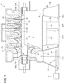
- FIG. 1 is a cross-sectional view schematically showing a configuration of a centrifugal compressor 1 according to an embodiment of the present invention.
- the centrifugal compressor 1 is a centrifugal compressor of a single-shaft multi-stage centrifugal type which includes a main casing 2, at least one impeller 3, intake casings 41, 42, discharge casings 51, 52, a cleaning-liquid injection device 6, and a cleaning-liquid supply device 7.
- the main casing 2 includes inlets 21, 22 and outlets 23, 24.
- the main casing 2 according to the present embodiment includes two inlets 21, 22 and two outlets 23, 24.
- a rotational shaft 37 is disposed rotatably through the main casing 2. Specifically, the rotational shaft 37 is supported rotatably by journal bearings 27A, 27B and thrust bearings 28A, 28B disposed on either side of the main casing 2.
- the inlets 21, 22 and the outlets 23, 24 are arranged along the rotational shaft 37, and the inlet 21, the outlet 23, the outlet 24, and the inlet 22 are arranged in this order from the left in FIG. 1 .
- the inlet 21 and the outlet 23 are adjacent and make a pair, while the inlet 22 and the outlet 24 are adjacent and make another pair.
- the outlet 23 and the inlet 22 are connected to each other by non-depicted piping.
- the main casing 2 houses at least one impeller 3 disposed rotatably inside thereof, including impellers 31 to 33, and impellers 34 to 36.
- the impellers 31 to 33 and the impellers 34 to 36 are fixed to the rotational shaft 37 concentrically. Specifically, the impellers 31 to 33 are fixed in series to a section of the rotational shaft 37 extending between the inlet 21 and the outlet 23, while the impellers 34 to 36 are fixed in series to a section of the rotational shaft 37 extending between the inlet 22 and the outlet 24.
- Each of the impellers 31 to 33 and the impellers 34 to 36 forms a flow path R inside the main casing 2.
- Diffusers 25, 26 are disposed inside the main casing 2, serving as a hydrostatic path connecting the flow paths R of the impellers 31 to 33 and of the impellers 34 to 36 in series.
- the intake casings 41, 42 have intake ports 41A, 42A connected to the inlets 21, 22 and disposed separate from the inlets 21, 22 downward, for instance, in the direction of the axes M, N of the intake casings 41, 42.
- the intake casings 41, 42 are reduced in diameter from the intake ports 41A, 42A toward the inlets 21, 22, and the flow-path cross-sectional areas gradually decrease from the intake ports 41A, 42A toward the inlets 21, 22.
- the intake casings 41, 42 have a flow-path cross-sectional shape gradually changing from a circular shape to a rectangular shape from the side of the intake ports 41A, 42A toward the side of the inlets 21, 22, so that the flow-path cross-sectional shape at the side of the intake ports 41A, 42A has a circular shape and the flow-path cross-sectional shape at the side of the inlets 21, 22 has a rectangular shape.
- the discharge casings 51, 52 have discharge ports 51A, 52A connected to the outlets 23, 24 and disposed separate from the outlets 23, 24 downward, for instance, in axial directions of the discharge casings 51, 52.
- directions of the axes M, N of the intake casings 41, 42 and the axial directions of the discharge casings 51, 52 are orthogonal to the axial direction of the rotational shaft 37.
- a fluid to be compressed flows into the intake casing 41 through the intake port 41A.
- the fluid to be compressed passes through the inlet 21, and then through the flow paths R of the impellers 31 to 33 in rotation, and the diffuser 25, thus being compressed.
- the compressed fluid passes through the outlet 23 and the discharge casing 51 to be discharged outside the main casing 2 temporarily.
- the fluid discharged from the discharge casing 51 is cooled by a non-depicted cooling device, for instance, and then flows into the intake casing 41 through the intake port 42A.
- the fluid having flown in passes through the inlet 22, and then through the flow paths R of the impellers 34 to 36 in rotation, and the diffuser 26, thus being compressed.
- the compressed fluid passes through the outlet 24 and the discharge casing 52 to be discharged outside the main casing 2.
- the cleaning-liquid injection device 6 can be disposed on the side of the intake port 41A inside the intake casing 41, and a cleaning liquid is supplied to the cleaning-liquid injection device 6 from a cleaning-liquid supply device 7.
- the cleaning-liquid injection device 6 is supplied with the cleaning liquid from the cleaning-liquid supply device 7 intermittently while the centrifugal compressor 1 is in operation.
- the cleaning liquid supplied from the cleaning-liquid injection device 6 is injected into a fluid to be compressed flowing into the casing 41, is dispersed over the fluid to be compressed, and reaches the surfaces of the impellers 31 to 33 with the fluid to be compressed.
- the cleaning liquid having reached the surfaces of the impellers 31 to 33 washes off dust adhering to the surfaces of the impellers 31 to 33 and cleans the surfaces of the impellers 31 to 33.
- the cleaning-liquid injection device 6 includes a pipe 61 capable of being disposed so as to extend along a plane which intersects with the direction of the axis M, and a plurality of injection holes 62 (see FIG. 3 ) disposed on the pipe 61, inside the intake casing 41.
- the cleaning liquid is injected through the plurality of injection holes 62, and thereby it is possible to disperse the cleaning liquid inside the intake casing 41. Accordingly, the cleaning liquid dispersed inside the intake casing 41 spreads out sufficiently before reaching the impellers 3, and thereby the cleaning liquid is distributed evenly over the entire region of the flow-path width, which makes it possible to clean the entire surfaces of the impellers 31 to 33 sufficiently and evenly.
- FIG. 2 is a vertical cross-sectional view, in which solid lines show the pipe 61 depicted in FIG. 1 in an operation position inside the intake casing 41, and virtual lines (two-dotted chain lines) show the pipe 61 refuged to a refuge position outside the intake casing 41.
- the pipe 61 is capable of reciprocating between the operation position inside the intake casing 41 and the refuge position outside the intake casing 41.
- the pipe 61 can be reciprocated manually or by a power device (not depicted).
- the pipe 61 can be manually reciprocated by rotating a handle (not depicted), or the pipe 61 can be reciprocated by a power device by operating the power device.
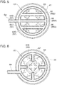
- FIGs. 3 to 6 are top cross-sectional views showing a cleaning-liquid injection device according to an embodiment.
- the pipe 61 includes an annular portion 63 having an annular shape in a top view, and injection holes 62A being at least a part of the plurality of injection holes 62 are disposed on the annular portion 63 so as to be distributed in the circumferential direction of the annular portion 63.
- the cleaning liquid is injected through the plurality of injection holes 62A disposed on the annular portion 63 so as to be distributed in the circumferential direction of the annular portion 63, and thereby it is possible to disperse the cleaning liquid in the circumferential direction of the annular portion 63, inside the intake casing 41.
- the cleaning liquid dispersed in the circumferential direction can be diffused before reaching the impeller 31.
- the cleaning liquid is distributed evenly over the entire region of the flow-path width, and the entire surfaces of the impellers 31 to 33 can be cleaned sufficiently and evenly.
- the diameter and installment position of the annular portion 63 can be set as needed.
- the diameter may be large so that the annular portion 63 extends along an inner wall of the intake casing 41, or may be of a size that makes internal contact with the inlet 21 and the annular portion 63 may be set concentrically with the center of the flow path. If the diameter is large so that the annular portion 63 extends along the inner wall of the intake casing 41, the cleaning liquid flows along the inner wall of the intake casing 41, and the cleaning liquid can be distributed to both sides of the flow-path width.
- the diameter is of a size that makes internal contact with the inlet 21, and the annular portion 63 is disposed concentric with the center of the flow path (center of the cross section), it is possible to suppress adherence of the cleaning liquid to the inner wall of the intake casing 41, and to reduce the amount of waste cleaning liquid that is not used in cleaning of the impellers 31 to 33.
- the injection holes 62A being at least a part of the plurality of injection holes 62 are disposed on the inner peripheral surface of the annular portion 63.
- the cleaning liquid is injected through the plurality of injection holes 62A disposed on the inner peripheral surface of the annular portion 63 toward the center of the annular portion 63, and thereby it is possible to disperse the cleaning liquid inside the annular portion 63 evenly in the circumferential direction. Since the injection direction of the cleaning liquid intersects with the flow direction of the fluid, the cleaning liquid dispersed evenly in the circumferential direction is spread out by the flow of the fluid. As a result, the cleaning liquid is distributed evenly over the entire region of the flow-path width, and the entire surfaces of the impellers 31 to 33 can be cleaned sufficiently and evenly.
- the cleaning liquid is injected inward in the radial direction from the annular portion 63, it is possible to suppress adherence of the cleaning liquid to the inner wall surface of the intake casing 41. In this way, it is possible to reduce the amount of waste cleaning fluid that is not used in cleaning of the impellers 31 to 33.
- the circumferential position and diameter of the plurality of injection holes 62A disposed on the inner peripheral surface of the annular portion 63 may be set as needed.
- the plurality of injection holes 62A may be distributed evenly in the circumferential direction of the annular portion 63 and formed to have the same diameter so that the cleaning liquid is injected evenly.
- the plurality of injection holes 62A may be distributed to be less dense in a region closer to a supply part 64 for supplying the cleaning liquid, and more dense in a region farther from the supply part 64, taking account of a pressure decrease inside the annular portion 63. Accordingly, the cleaning liquid is injected evenly inside the intake casing 41, and the cleaning liquid is distributed evenly over the entire region of the flow-path width, whereby the entire surfaces of the impellers 31 to 33 can be cleaned sufficiently and evenly.
- FIG. 7 is a traverse cross-sectional view schematically showing a cleaning-liquid injection device according to an embodiment.
- injection holes 62B being at least a part the plurality of injection holes 62 are disposed on the upstream side of the annular portion 63, and have openings facing obliquely upward.
- the cleaning liquid is injected obliquely upward from the plurality of injection holes 62B disposed on the upstream side of the annular portion 63, and thereby the cleaning liquid is adequately diffused by the fluid H flowing inside the intake casing 41.
- the cleaning liquid is distributed evenly over the entire region of the flow-path width, and the entire surfaces of the impellers 31 to 33 can be cleaned sufficiently and evenly.
- the circumferential position and diameter of the plurality of injection holes 62B disposed on the upstream side of the annular portion 63 may be set as needed.
- the plurality of injection holes 62B may be distributed evenly in the annular portion 63 and formed to have the same diameter so that the cleaning liquid is injected evenly.
- the plurality of injection holes 62A may be distributed to be less dense in a region closer to the supply part 64 for supplying the cleaning liquid, and more dense in a region farther from the supply part 64, taking account of a pressure decrease inside the annular portion 63. Accordingly, the cleaning liquid is injected evenly inside the intake casing 41, and the cleaning liquid is distributed evenly over the entire region of the flow-path width, whereby the entire surfaces of the impellers 31 to 33 can be cleaned sufficiently and evenly.
- the pipe 61 includes a small-diameter annular portion 65 having an annular shape in a top view and a smaller diameter than the annular portion 63, disposed concentrically with the annular portion 63, and injection holes 62C being at least a part of the plurality of injection holes 62 are disposed on the small-diameter annular portion 65 so as to be distributed in the circumferential direction of the small-diameter annular portion 65.
- the cleaning liquid is injected through the plurality of injection holes 62C disposed on the small-diameter annular portion 65 so as to be distributed in the circumferential direction of the small-diameter annular portion 65, and thereby it is possible to supply the cleaning liquid to the center region inside the intake casing 41 away from the annular portion 63.
- the cleaning liquid injected from the injection holes 62C disposed on the small-diameter annular portion 65 is diffused sufficiently by a fluid flowing in the center region inside the intake casing 41.
- the cleaning liquid is distributed evenly over the entire region of the flow-path width, and the entire surfaces of the impellers 31 to 33 can be cleaned sufficiently and evenly.
- the diameter of the small-diameter annular portion 65 only needs to be smaller than that of the annular portion 63.
- the diameter of the annular portion 63 may be large so that the annular portion 63 extends along the inner wall of the intake casing 41, and the diameter of the small-diameter annular portion 65 may be of a size that makes internal contact with the inlet 21 and the small-diameter annular portion 63 may be disposed centered at the center of the flow path.
- the small-diameter annular portion 65 does not need to be flush with the annular portion, and may be disposed downstream of the annular portion 63, for instance.
- the circumferential position and diameter of the plurality of injection holes 62C disposed on the small-diameter annular portion 65 may be set as needed.
- the plurality of injection holes 62C may be distributed evenly in the circumferential direction of the small-diameter annular portion 65 and formed to have the same diameter so that the cleaning liquid is injected evenly.
- the plurality of injection holes 62C may be distributed to be less dense in a region closer to the supply part 64 for supplying the cleaning liquid, and more dense in a region farther from the supply part 64, taking account of a pressure decrease inside the small-diameter annular portion 65. Accordingly, the cleaning liquid is injected evenly inside the intake casing 41, and the cleaning liquid is distributed evenly over the entire region of the flow-path width, whereby the entire surfaces of the impellers 31 to 33 can be cleaned sufficiently and evenly.
- the pipe 61 includes at least one linear portion 66 connecting two points on the circumference of the annular portion 63, and injection holes 62D being at least a part of the plurality of injection holes 62 is disposed on the linear portion 66 so as to be distributed in the longitudinal direction of the linear portion 66.
- the cleaning liquid is injected through the plurality of injection holes 62D distributed in the longitudinal direction of the linear portion 66 connecting two points on the annular portion 63, and thereby it is possible to supply the cleaning liquid to the center region inside the intake casing 41 away from the annular portion 63.
- the cleaning liquid injected from the injection holes 62D disposed on the linear portion 66 is diffused sufficiently by a fluid flowing in the center region inside the intake casing 41.
- the cleaning liquid is distributed evenly over the entire region of the flow-path width, and the entire surfaces of the impellers 31 to 33 can be cleaned sufficiently and evenly.
- the circumferential position and diameter of the plurality of injection holes 62D disposed on the linear portion 66 may be set as needed.
- the plurality of injection holes 62D may be provided at regular intervals, or to be less dense in a region closer to the supply part 64 and more dense in a region farther from the supply part so that the cleaning liquid is injected evenly.
- the plurality of injection holes 62D have the same diameter, and the same flow amount of cleaning liquid is injected from the injection holes 62D. Accordingly, the entire surfaces of the impellers 31 to 33 can be cleaned sufficiently and evenly.
- the pipe 61 includes a first linear portion 66A passing through the center of the annular portion, and a second linear portion 66B disposed parallel to the first linear portion 66A on both sides of the first linear portion 66A.
- the injection holes 62D being at least a part of the plurality of injection holes 62 are disposed on the first linear portion 66A and the second linear portion 66B so as to be distributed in the longitudinal direction of the first linear portion 66A and the second linear portion 66B.
- the plurality of injection holes 62D are disposed on both sides of the first linear portion 66A at least in the width direction of the first linear portion 66A.
- the cleaning liquid is injected from the plurality of injection holes 62D disposed so as to be distributed in the longitudinal direction of the first linear portion 66, and thereby the cleaning liquid is adequately diffused by the fluid flowing through the center region inside the intake casing 41.
- the cleaning liquid is distributed evenly over the entire region of the flow-path width, and the entire surfaces of the impellers 31 to 33 can be cleaned sufficiently and evenly.
- the circumferential position and diameter of the plurality of injection holes 62D disposed in the longitudinal direction of the first linear portion 66A and the second linear portion 66B may be set as needed.
- the plurality of injection holes 62D may be disposed on the first linear portion 66A and the second linear portion 66B so as to be distributed in the longitudinal direction of the first linear portion 66A and the second linear portion 66B so that the cleaning liquid is injected evenly.
- the plurality of injection holes 62D have the same diameter, and the same flow amount of cleaning liquid is injected through the injection holes 62D. Accordingly, the cleaning liquid is injected evenly, and the cleaning liquid is distributed evenly over the entire region of the flow-path width, whereby the entire surfaces of the impellers 31 to 33 can be cleaned sufficiently and evenly.
- the pipe 61 includes at least one protruding portion 67 protruding toward the center in the radial direction from the annular portion 63, and injection holes 62E being at least a part of the plurality of injection holes 62 are disposed on the protruding portion 67.
- the cleaning liquid is injected through the plurality of injection holes 62E disposed on the protruding portion 67, and thereby it is possible to supply the cleaning liquid reliably to the center region inside the intake casing 41 away from the annular portion 63.
- the cleaning liquid injected from the injection holes 62E disposed on the protruding portion 67 is diffused sufficiently by a fluid flowing in the center region inside the intake casing 41.
- the cleaning liquid is distributed evenly over the entire region of the flow-path width, and the entire surfaces of the impellers 31 to 33 can be cleaned sufficiently and evenly.
- the pipe 61 includes four protruding portions 67 protruding toward the center in the radial direction from respective positions that divide the annular portion 63 into four sections in the circumferential direction (the annular portion 63), and injection holes 62E being at least a part of the plurality of injection holes 62 are disposed on the protruding portions 67. More specifically, the injection holes 62E being at least a part of the injection holes 62 is disposed on tips of the protruding portions 67 and on both sides of the protruding portions 67 in the width direction of the protruding portions 67.
- the cleaning liquid is injected from the plurality of injection holes 62E disposed on the protruding portions 67, and thereby the cleaning liquid is adequately diffused by the fluid flowing through the center region inside the intake casing 41.
- the cleaning liquid is distributed evenly over the entire region of the flow-path width, and the entire surfaces of the impellers 31 to 33 can be cleaned sufficiently and evenly.
- FIG. 8 is a top cross-sectional view schematically showing a cleaning-liquid injection device according to an embodiment.
- the pipe 61 includes at least one linear portion 68 having a linear shape, and a plurality of injection holes 62E is disposed on the at least one linear portion 68 so as to be distributed in the longitudinal direction of the at least one linear portion 68.
- the cleaning liquid is injected through the plurality of injection holes 62E disposed so as to be distributed on the linear portion 68, and thereby it is possible to disperse the cleaning liquid in the longitudinal direction of the linear portion, inside the intake casing 41.
- the cleaning liquid dispersed in the longitudinal direction can be diffused before reaching the impellers 31 to 33.
- the cleaning liquid is distributed evenly over the entire region of the flow-path width, and the entire surfaces of the impellers 31 to 33 can be cleaned sufficiently and evenly.
- the installment position of the linear portion 68 can be set as needed.
- the installment position may be set so as to intersect the flow path of the intake casing 41.
- the cleaning liquid is injected evenly to the center of the flow path of the casing 41 as well, thus being distributed evenly over the entire region of the flow-path width, whereby the entire surfaces of the impellers 31 to 33 can be cleaned sufficiently and evenly.
- FIG. 9 is a traverse cross-sectional view schematically showing a cleaning-liquid injection device according to an embodiment.
- a plurality of injection holes 62F are disposed on the upstream side of the at least one linear portion 68, and have openings facing obliquely upward.
- the cleaning liquid is injected obliquely upward from the plurality of injection holes 62F disposed on the upstream side of the at least one linear portion 68, and thereby the cleaning liquid is adequately diffused by the fluid H flowing inside the intake casing 41.
- the cleaning liquid is distributed evenly over the entire region of the flow-path width, and the entire surfaces of the impellers 31 to 33 can be cleaned sufficiently and evenly.
- the longitudinal-directional position and diameter of the plurality of injection holes 62F disposed on the upstream side of the linear portion 68 may be set as needed.
- the plurality of injection holes 62F may be distributed at regular intervals so that the cleaning liquid is injected evenly.
- the injection holes 62F may be disposed to be more dense in a central area and less dense in side regions on both sides of the central area, or may be disposed to be less dense in the central area and more dense in the side regions.
- the plurality of injection holes 62F have the same diameter, and the same flow amount of cleaning liquid is injected through the injection holes 62F. Accordingly, the cleaning liquid is injected evenly, and the cleaning liquid is distributed evenly over the entire region of the flow-path width, whereby the entire surfaces of the impellers 31 to 33 can be cleaned sufficiently and evenly.
- the plurality of injection holes 62F is disposed on both sides of the at least one linear portion 68 in the width direction of the at least one linear portion 68.
- the cleaning liquid is injected through the plurality of injection holes 62F disposed on both sides of the at least one linear portion 68 in the width direction of the at least one linear portion 68, and thereby it is possible to disperse the cleaning liquid in the longitudinal direction of the linear portion 68, inside the intake casing 41.
- the cleaning liquid dispersed evenly along the longitudinal direction of the linear portion 68 can be dispersed before reaching the impellers 31 to 33.
- the cleaning liquid is distributed evenly over the entire region of the flow-path width, and the entire surfaces of the impellers 31 to 33 can be cleaned sufficiently and evenly.
- a cross-sectional shape can be selected with no particular limit for the pipe 61, the annular portion 63, the small-diameter annular portion 65, the linear portion 66, the first linear portion 66A, the second linear portion 66B, the protruding portion 67, and the linear portion 68 described above, as long as the cross-sectional shape is suitable for injection of a cleaning liquid.
- a circular shape, an oval shape, an ellipse shape, a streamline shape, or a droplet shape can be selected.
- a flow-path cross-sectional area can be set with no particular limit for the pipe 61, the annular portion 63, the small-diameter annular portion 65, the linear portion 66, the first linear portion 66A, the second linear portion 66B, the protruding portion 67, and the linear portion 68, as long as the flow-path cross-sectional area is suitable for injection of a cleaning liquid.
- a flow-path cross-sectional area is set so that the flow amount or pressure of the cleaning liquid injected from the plurality of injection holes 62, 62A, 62B, 62C, 62D, 62E are even.
- the flow-path cross-sectional area of the pipe 61, the annular portion 63, the small-diameter annular portion 65, the linear portion 66, the first linear portion 66A, the second linear portion 66B, the protruding portion 67, and the linear portion 68 is set to be more than ten times of the cross-sectional area of the injection holes 62A, 62B, 62C, 62D, and 62E.
- the pipe 61 may include the annular portion 63 and the linear portion 68, and the annular portion 63 and the linear portion 68 may be disposed in positions offset in the direction of the axis M. In this case, it is preferable to position the annular portion 63 at the inlet 21, and the linear portion 68 between the annular portion and the inlet 21.
Landscapes
- Engineering & Computer Science (AREA)
- Mechanical Engineering (AREA)
- General Engineering & Computer Science (AREA)
- Physics & Mathematics (AREA)
- Fluid Mechanics (AREA)
- Structures Of Non-Positive Displacement Pumps (AREA)
- Cleaning By Liquid Or Steam (AREA)
Applications Claiming Priority (2)
| Application Number | Priority Date | Filing Date | Title |
|---|---|---|---|
| JP2014191514A JP2016061261A (ja) | 2014-09-19 | 2014-09-19 | 遠心圧縮機 |
| PCT/JP2015/061885 WO2016042826A1 (ja) | 2014-09-19 | 2015-04-17 | 遠心圧縮機 |
Publications (1)
| Publication Number | Publication Date |
|---|---|
| EP3196481A1 true EP3196481A1 (en) | 2017-07-26 |
Family
ID=55532873
Family Applications (1)
| Application Number | Title | Priority Date | Filing Date |
|---|---|---|---|
| EP15842413.5A Withdrawn EP3196481A1 (en) | 2014-09-19 | 2015-04-17 | Centrifugal compressor |
Country Status (5)
| Country | Link |
|---|---|
| US (1) | US20170226881A1 (enExample) |
| EP (1) | EP3196481A1 (enExample) |
| JP (1) | JP2016061261A (enExample) |
| CN (1) | CN106471261A (enExample) |
| WO (1) | WO2016042826A1 (enExample) |
Cited By (1)
| Publication number | Priority date | Publication date | Assignee | Title |
|---|---|---|---|---|
| EP3643923A1 (en) * | 2018-10-25 | 2020-04-29 | Mitsubishi Heavy Industries Compressor Corporation | Compressor |
Families Citing this family (3)
| Publication number | Priority date | Publication date | Assignee | Title |
|---|---|---|---|---|
| IT201800021067A1 (it) * | 2018-12-27 | 2020-06-27 | Nuovo Pignone Tecnologie Srl | Componenti aerodinamici statorici con ugelli e metodi per pulire una turbomacchina |
| CN118622712B (zh) * | 2024-08-09 | 2024-10-18 | 佛山市肯富来工业泵有限公司 | 一种多级离心泵 |
| CN118959330B (zh) * | 2024-10-14 | 2025-01-24 | 深圳市大麦智创科技有限公司 | 一种工业冷风机用气流驱动组件及其驱动方法 |
Family Cites Families (9)
| Publication number | Priority date | Publication date | Assignee | Title |
|---|---|---|---|---|
| JPH05141397A (ja) * | 1991-11-15 | 1993-06-08 | Hitachi Ltd | 羽根車を有する回転機械の羽根車洗浄装置 |
| JPH07269302A (ja) * | 1994-03-30 | 1995-10-17 | Mitsubishi Heavy Ind Ltd | 軸流圧縮機の翼洗浄方法および装置 |
| JPH08338397A (ja) * | 1995-06-14 | 1996-12-24 | Hitachi Ltd | 一軸多段遠心圧縮機の羽根車洗浄装置 |
| US6413043B1 (en) * | 2000-11-09 | 2002-07-02 | General Electric Company | Inlet guide vane and shroud support contact |
| US20070028947A1 (en) * | 2005-08-04 | 2007-02-08 | General Electric Company | Gas turbine on-line compressor water wash system |
| US7703272B2 (en) * | 2006-09-11 | 2010-04-27 | Gas Turbine Efficiency Sweden Ab | System and method for augmenting turbine power output |
| US8197609B2 (en) * | 2006-11-28 | 2012-06-12 | Pratt & Whitney Line Maintenance Services, Inc. | Automated detection and control system and method for high pressure water wash application and collection applied to aero compressor washing |
| EP2052792A3 (en) * | 2007-10-09 | 2011-06-22 | Gas Turbine Efficiency Sweden AB | Drain valve, washing system and sensing of rinse and wash completion |
| US9016293B2 (en) * | 2009-08-21 | 2015-04-28 | Gas Turbine Efficiency Sweden Ab | Staged compressor water wash system |
-
2014
- 2014-09-19 JP JP2014191514A patent/JP2016061261A/ja not_active Withdrawn
-
2015
- 2015-04-17 CN CN201580035234.2A patent/CN106471261A/zh active Pending
- 2015-04-17 EP EP15842413.5A patent/EP3196481A1/en not_active Withdrawn
- 2015-04-17 US US15/503,145 patent/US20170226881A1/en not_active Abandoned
- 2015-04-17 WO PCT/JP2015/061885 patent/WO2016042826A1/ja not_active Ceased
Cited By (2)
| Publication number | Priority date | Publication date | Assignee | Title |
|---|---|---|---|---|
| EP3643923A1 (en) * | 2018-10-25 | 2020-04-29 | Mitsubishi Heavy Industries Compressor Corporation | Compressor |
| US11073167B2 (en) | 2018-10-25 | 2021-07-27 | Mitsubishi Heavy Industries Compressor Corporation | Compressor |
Also Published As
| Publication number | Publication date |
|---|---|
| CN106471261A (zh) | 2017-03-01 |
| JP2016061261A (ja) | 2016-04-25 |
| US20170226881A1 (en) | 2017-08-10 |
| WO2016042826A1 (ja) | 2016-03-24 |
Similar Documents
| Publication | Publication Date | Title |
|---|---|---|
| EP3196481A1 (en) | Centrifugal compressor | |
| US10458438B2 (en) | Centrifugal compressor | |
| CN204900542U (zh) | 航空用主轴轴承以及叶轮式径向收油环 | |
| CN106574631B (zh) | 压缩机壳、离心压缩机及增压器、以及压缩机壳的制造方法 | |
| JP2010203251A (ja) | 吸込みケーシング及び流体機械 | |
| CN106232237B (zh) | 离心分离器 | |
| JP5553847B2 (ja) | 複数入口式真空ポンプ | |
| JP2013204550A5 (enExample) | ||
| US20160177970A1 (en) | Blower | |
| CN202073830U (zh) | 泵浦叶轮 | |
| US11131319B2 (en) | Centrifugal compressor | |
| JP6521702B2 (ja) | ターボ型流体機械の洗浄装置及びターボ型流体機械 | |
| US20150354588A1 (en) | Centrifugal compressor | |
| JP2016061261A5 (enExample) | ||
| EP1795759A2 (en) | Centrifugal impeller and pump apparatus | |
| US20150260202A1 (en) | Pump device | |
| CN113309189A (zh) | 水栓装置 | |
| US11041497B1 (en) | Centrifugal rotary machine | |
| CN103261697B (zh) | 多级泵 | |
| CN107250555A (zh) | 动叶片以及轴流式旋转机械 | |
| JP6169007B2 (ja) | 動翼、及び軸流回転機械 | |
| US10465687B2 (en) | Device for conditioning flow of working fluids | |
| US20210164489A1 (en) | Compressor having extended range and stability | |
| CN106415022A (zh) | 干气提取装置及方法 | |
| JP7243096B2 (ja) | エジェクタ |
Legal Events
| Date | Code | Title | Description |
|---|---|---|---|
| PUAI | Public reference made under article 153(3) epc to a published international application that has entered the european phase |
Free format text: ORIGINAL CODE: 0009012 |
|
| 17P | Request for examination filed |
Effective date: 20170210 |
|
| AK | Designated contracting states |
Kind code of ref document: A1 Designated state(s): AL AT BE BG CH CY CZ DE DK EE ES FI FR GB GR HR HU IE IS IT LI LT LU LV MC MK MT NL NO PL PT RO RS SE SI SK SM TR |
|
| AX | Request for extension of the european patent |
Extension state: BA ME |
|
| DAV | Request for validation of the european patent (deleted) | ||
| DAX | Request for extension of the european patent (deleted) | ||
| STAA | Information on the status of an ep patent application or granted ep patent |
Free format text: STATUS: THE APPLICATION HAS BEEN WITHDRAWN |
|
| 18W | Application withdrawn |
Effective date: 20180410 |