EP3196422B1 - Cadre d'échappement - Google Patents
Cadre d'échappement Download PDFInfo
- Publication number
- EP3196422B1 EP3196422B1 EP17152469.7A EP17152469A EP3196422B1 EP 3196422 B1 EP3196422 B1 EP 3196422B1 EP 17152469 A EP17152469 A EP 17152469A EP 3196422 B1 EP3196422 B1 EP 3196422B1
- Authority
- EP
- European Patent Office
- Prior art keywords
- passage
- circumferential wall
- diffuser
- cooling passage
- exhaust frame
- Prior art date
- Legal status (The legal status is an assumption and is not a legal conclusion. Google has not performed a legal analysis and makes no representation as to the accuracy of the status listed.)
- Active
Links
- 238000001816 cooling Methods 0.000 claims description 130
- 238000004891 communication Methods 0.000 claims description 55
- 239000000567 combustion gas Substances 0.000 claims description 30
- 238000011144 upstream manufacturing Methods 0.000 claims description 6
- 230000037361 pathway Effects 0.000 claims 1
- 239000007789 gas Substances 0.000 description 21
- 230000001965 increasing effect Effects 0.000 description 15
- 230000000694 effects Effects 0.000 description 8
- 238000000034 method Methods 0.000 description 8
- 230000000052 comparative effect Effects 0.000 description 5
- 239000002826 coolant Substances 0.000 description 4
- 238000002485 combustion reaction Methods 0.000 description 3
- 230000003247 decreasing effect Effects 0.000 description 3
- 239000012530 fluid Substances 0.000 description 3
- 239000000446 fuel Substances 0.000 description 2
- 239000003779 heat-resistant material Substances 0.000 description 2
- 238000004519 manufacturing process Methods 0.000 description 2
- 230000015572 biosynthetic process Effects 0.000 description 1
- 230000008878 coupling Effects 0.000 description 1
- 238000010168 coupling process Methods 0.000 description 1
- 238000005859 coupling reaction Methods 0.000 description 1
- 230000001419 dependent effect Effects 0.000 description 1
- 238000011161 development Methods 0.000 description 1
- 230000018109 developmental process Effects 0.000 description 1
- 230000002708 enhancing effect Effects 0.000 description 1
- 238000010248 power generation Methods 0.000 description 1
- 239000011369 resultant mixture Substances 0.000 description 1
- 230000000630 rising effect Effects 0.000 description 1
- 238000007789 sealing Methods 0.000 description 1
Images


Classifications
-
- F—MECHANICAL ENGINEERING; LIGHTING; HEATING; WEAPONS; BLASTING
- F01—MACHINES OR ENGINES IN GENERAL; ENGINE PLANTS IN GENERAL; STEAM ENGINES
- F01D—NON-POSITIVE DISPLACEMENT MACHINES OR ENGINES, e.g. STEAM TURBINES
- F01D25/00—Component parts, details, or accessories, not provided for in, or of interest apart from, other groups
- F01D25/30—Exhaust heads, chambers, or the like
-
- F—MECHANICAL ENGINEERING; LIGHTING; HEATING; WEAPONS; BLASTING
- F01—MACHINES OR ENGINES IN GENERAL; ENGINE PLANTS IN GENERAL; STEAM ENGINES
- F01D—NON-POSITIVE DISPLACEMENT MACHINES OR ENGINES, e.g. STEAM TURBINES
- F01D25/00—Component parts, details, or accessories, not provided for in, or of interest apart from, other groups
- F01D25/08—Cooling; Heating; Heat-insulation
- F01D25/12—Cooling
-
- F—MECHANICAL ENGINEERING; LIGHTING; HEATING; WEAPONS; BLASTING
- F01—MACHINES OR ENGINES IN GENERAL; ENGINE PLANTS IN GENERAL; STEAM ENGINES
- F01D—NON-POSITIVE DISPLACEMENT MACHINES OR ENGINES, e.g. STEAM TURBINES
- F01D25/00—Component parts, details, or accessories, not provided for in, or of interest apart from, other groups
- F01D25/08—Cooling; Heating; Heat-insulation
- F01D25/14—Casings modified therefor
-
- F—MECHANICAL ENGINEERING; LIGHTING; HEATING; WEAPONS; BLASTING
- F01—MACHINES OR ENGINES IN GENERAL; ENGINE PLANTS IN GENERAL; STEAM ENGINES
- F01D—NON-POSITIVE DISPLACEMENT MACHINES OR ENGINES, e.g. STEAM TURBINES
- F01D25/00—Component parts, details, or accessories, not provided for in, or of interest apart from, other groups
- F01D25/24—Casings; Casing parts, e.g. diaphragms, casing fastenings
- F01D25/26—Double casings; Measures against temperature strain in casings
-
- F—MECHANICAL ENGINEERING; LIGHTING; HEATING; WEAPONS; BLASTING
- F01—MACHINES OR ENGINES IN GENERAL; ENGINE PLANTS IN GENERAL; STEAM ENGINES
- F01D—NON-POSITIVE DISPLACEMENT MACHINES OR ENGINES, e.g. STEAM TURBINES
- F01D9/00—Stators
- F01D9/06—Fluid supply conduits to nozzles or the like
- F01D9/065—Fluid supply or removal conduits traversing the working fluid flow, e.g. for lubrication-, cooling-, or sealing fluids
-
- F—MECHANICAL ENGINEERING; LIGHTING; HEATING; WEAPONS; BLASTING
- F02—COMBUSTION ENGINES; HOT-GAS OR COMBUSTION-PRODUCT ENGINE PLANTS
- F02C—GAS-TURBINE PLANTS; AIR INTAKES FOR JET-PROPULSION PLANTS; CONTROLLING FUEL SUPPLY IN AIR-BREATHING JET-PROPULSION PLANTS
- F02C7/00—Features, components parts, details or accessories, not provided for in, or of interest apart form groups F02C1/00 - F02C6/00; Air intakes for jet-propulsion plants
- F02C7/12—Cooling of plants
- F02C7/16—Cooling of plants characterised by cooling medium
- F02C7/18—Cooling of plants characterised by cooling medium the medium being gaseous, e.g. air
-
- F—MECHANICAL ENGINEERING; LIGHTING; HEATING; WEAPONS; BLASTING
- F05—INDEXING SCHEMES RELATING TO ENGINES OR PUMPS IN VARIOUS SUBCLASSES OF CLASSES F01-F04
- F05D—INDEXING SCHEME FOR ASPECTS RELATING TO NON-POSITIVE-DISPLACEMENT MACHINES OR ENGINES, GAS-TURBINES OR JET-PROPULSION PLANTS
- F05D2260/00—Function
- F05D2260/20—Heat transfer, e.g. cooling
-
- F—MECHANICAL ENGINEERING; LIGHTING; HEATING; WEAPONS; BLASTING
- F05—INDEXING SCHEMES RELATING TO ENGINES OR PUMPS IN VARIOUS SUBCLASSES OF CLASSES F01-F04
- F05D—INDEXING SCHEME FOR ASPECTS RELATING TO NON-POSITIVE-DISPLACEMENT MACHINES OR ENGINES, GAS-TURBINES OR JET-PROPULSION PLANTS
- F05D2260/00—Function
- F05D2260/94—Functionality given by mechanical stress related aspects such as low cycle fatigue [LCF] of high cycle fatigue [HCF]
- F05D2260/941—Functionality given by mechanical stress related aspects such as low cycle fatigue [LCF] of high cycle fatigue [HCF] particularly aimed at mechanical or thermal stress reduction
-
- Y—GENERAL TAGGING OF NEW TECHNOLOGICAL DEVELOPMENTS; GENERAL TAGGING OF CROSS-SECTIONAL TECHNOLOGIES SPANNING OVER SEVERAL SECTIONS OF THE IPC; TECHNICAL SUBJECTS COVERED BY FORMER USPC CROSS-REFERENCE ART COLLECTIONS [XRACs] AND DIGESTS
- Y02—TECHNOLOGIES OR APPLICATIONS FOR MITIGATION OR ADAPTATION AGAINST CLIMATE CHANGE
- Y02T—CLIMATE CHANGE MITIGATION TECHNOLOGIES RELATED TO TRANSPORTATION
- Y02T50/00—Aeronautics or air transport
- Y02T50/60—Efficient propulsion technologies, e.g. for aircraft
Definitions
- the present invention relates to an exhaust frame for a gas turbine.
- US 2003/161718 A1 describes an apparatus and a system for thermally isolating a gas turbine housing from the significantly high temperatures associated with the combustion gases flowing through the housing.
- EP 2 578 816 A2 describes a system including a turbine exhaust section.
- the turbine exhaust section includes an outer structure having an outer casing, an outer exhaust wall disposed along the exhaust flow path, and an outer cavity disposed between the outer exhaust wall and the outer casing.
- the turbine exhaust section further includes a strut extending between the outer structure and the inner structure.
- the strut includes a first flow passage configured to flow a fluid from the inner cavity to the outer cavity.
- the inter-strut space is defined in a tubular shape such as to covert the strut which extends across the combustion gas passage at a position on the downstream side as compared to the cooling air supply hole and the final stage wheel space in the flow direction of the combustion gas. Therefore, as compared to the flow path length in the case of flowing by way of that portion of the inter-strut space which is the nearest to the cooling air supply hole (this portion will hereinafter be referred to as the near-side space), the flow path length in the case of flowing by way of that portion of the inter-strut space which is the farthest from the cooling air supply hole (this portion will hereinafter be referred to as the far-side space) is longer.
- the pressure loss of cooling air which flows through a passage or flow path is smaller as the flow path length is shorter.
- the flow rate of the cooling air is increased as the pressure loss is reduced.
- JP-2005-83199-A therefore, the flow rate of the cooling air flowing via the near-side space is increased, whereas the flow rate of the cooling air flowing via the far-side space is decreased.
- the cooling air flowing by way of the far-side space When the flow rate of the cooling air flowing by way of the far-side space is decreased, the cooling air becomes liable to stagnate in the passage in the vicinity of the inlet of the far-side space. In this case, the cooling efficiency for the exhaust frame may be lowered in the vicinity of the inlet of the far-side space.
- the present invention has been devised in view of the above and an object of the present invention is to restrain the cooling efficiency for an exhaust frame from being lowered.
- an exhaust frame connected to an outlet for a combustion gas of a turbine, the exhaust frame including: an inner casing; an inner diffuser which covers an outer side of the inner casing and which defines, between the inner diffuser and the inner casing, an annular inner cooling passage connected to a final-stage wheel space of the turbine; an outer diffuser which covers an outer side of the inner diffuser and which defines an exhaust passage for the combustion gas between the outer diffuser and the inner diffuser; an outer casing which covers an outer side of the outer diffuser and which defines an annular outer cooling passage between the outer casing and the outer diffuser; a strut which connects the inner casing and the outer casing to each other while crossing the exhaust passage; a strut cover which connects the inner diffuser and the outer diffuser to each other, covers the strut, and which defines, between the strut cover and the strut, an annular connection passage connecting the inner cooling passage and the outer
- FIG. 1 illustrates a configuration example of a gas turbine provided with an exhaust frame according to a first embodiment.
- the exhaust frame according to this embodiment is applied, for example, to a heavy structure type gas turbine that is disposed on the ground and used mainly for power generation.
- the gas turbine 100 includes a compressor 1, a combustor 2, a turbine 3 and an exhaust frame 4.
- the compressor 1 and the turbine 3 are connected to each other through a shaft (not shown).
- the compressor 1, which is rotationally driven by the turbine 3, compresses air 6 sucked in through a suction part 5 to generate high-pressure air (combustion air), and supplies the high-pressure air to the combustor 2.
- the combustor 2 mixes the high-pressure air supplied from the compressor 1 with a fuel supplied from a fuel system (not shown), burns a resultant mixture to generate a high-temperature combustion gas 7, and supplies the combustion gas 7 to the turbine 3.
- the turbine 3 is rotationally driven through expansion of the combustion gas 7 supplied from the combustor 2.
- the turbine 3 or the compressor 1 is connected with a load apparatus (not shown).
- a generator is connected to the turbine 3 as a load apparatus, and motive power obtained by subtracting motive power for driving the compressor 1 from rotational power of the turbine 3 is converted into electric power by the generator.
- the combustion gas 7 having driven the turbine 3 flows into the exhaust frame 4 as a turbine exhaust gas, and is released to the atmospheric air via the exhaust frame 4 and an exhaust duct (not shown).
- the exhaust frame 4 is provided on the downstream side of the turbine 3 with respect to the flow direction of the combustion gas 7, and connects an outlet for a combustion gas 7 of the turbine 3 and the exhaust duct to each other.
- the upstream and downstream with respect to the flow direction of the combustion gas 7 will hereinafter referred to simply as “upstream” and “downstream,” respectively.
- FIG. 2 is a schematic configuration view of the exhaust frame according to this embodiment
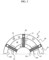
- FIG. 3 is a sectional view in an arrow direction taken along line III-III of FIG. 2
- the exhaust frame 4 according to this embodiment includes a casing 9, an upstream-side diffuser 10, strut 11, strut cover 12, a downstream-side diffuser 13 and communication holes 24.
- the casing 9 constitutes a part of a circumferential wall of the exhaust frame 4.
- the casing 9 includes an inner casing 9A and an outer casing 9B, with an annular space defined inside thereof.
- the upstream-side diffuser 10 is accommodated in the casing 9.
- the upstream-side diffuser 10 includes an inner diffuser 10A and an outer diffuser 10B.
- the inner casing 9A is a conical surface-shaped member which constitutes an inner circumferential wall of the casing 9.
- the inner diffuser 10A is a conical surface-shaped member formed such as to cover the outer side of the inner casing 9A, and constitutes an inner circumferential wall of the upstream-side diffuser 10.
- a final stage wheel 25 which includes final stage moving blades 27 of the turbine 3.
- the inner casing 9A and the inner diffuser 10A are spaced downstream from the final stage wheel 25 such as to secure a space (final stage wheel space) 21 between their upstream-side end portions and the final stage wheel 25.
- An annular space defined between the inner diffuser 10A and the inner casing 9A constitutes a passage (inner cooling passage) 16 through which cooling air supplied into the exhaust frame 4 flows.
- the inner cooling passage 16 communicates with the final stage wheel space 21.
- the outer diffuser 10B is a conical surface-shaped member formed such as to cover the outer side of the inner diffuser 10A, and constitutes an outer circumferential wall of the upstream-side diffuser 10.
- An annular space defined between the inner diffuser 10A and the outer diffuser 10B constitutes a passage (exhaust passage) 18 through which the combustion gas 7 from the turbine 3 flows.
- the outer casing 9B is a conical surface-shaped member formed such as to cover the outer side of the outer diffuser 10B, and constitutes an outer circumferential wall of the casing 9.
- An annular space defined between the outer diffuser 10B and the outer casing 9B constitutes a passage (outer cooling passage) 19 through which cooling air supplied into the exhaust frame 4 flows.
- the outer cooling passage 19 is provided with a cooling medium supply hole 15.
- the cooling medium supply hole 15 is a cooling air introduction hole provided in the outer cooling passage 19 at a position on the upstream side of connection passages 22 (described later). In this embodiment, a portion of the high-pressure air generated by the compressor 1 (see FIG. 1 ) is extracted and is supplied through the cooling medium supply hole 15 into the exhaust frame 4 as cooling air 23.
- the struts 11 are provided such as to cross the exhaust passage 18 at positions on the downstream side, in the inner diffuser 10A and the outer diffuser 10B, and connect the inner casing 9A and the outer casing 9B to each other.
- the outer casing 9B described above is supported by a turbine stand (not shown), and the struts 11 play the role of supporting the inner casing 9A relative to the outer casing 9B.
- the struts 11 are provided (in this embodiment, six) at regular intervals along the circumferential direction of the inner casing 9A. As shown in FIG.
- the struts 11 extend radially from the inner casing 9A in the radial directions of the casing 9 (in the directions from the inner casing 9A toward the outer casing 9B). It is to be noted, however, that the struts 11 may be provided to extend from the inner casing 9A in the state of being inclined in the circumferential direction in relation to the radial direction of the casing 9.
- the strut covers 12 connect the inner diffuser 10A and the outer diffuser 10B to each other, and are provided in such a manner that each strut cover 12 covers the outer side of the strut 11 as viewed in a section extending in the rotating direction (circumferential direction) of the turbine 3.
- Annular spaces each defined between the strut 11 and the strut cover 12 constitute passages (connection passages) 22 connecting the inner cooling passage 16 and the outer cooling passage 19 to each other.
- the downstream-side diffuser 13 is connected to the downstream side of the upstream-side diffuser 10 through a flange 20. A downstream-side end portion of the outer cooling passage 19 is closed with the flange 20 for the outer diffuser 10B and the downstream-side diffuser 13 that are connected to each other.
- the downstream-side diffuser 13 includes an inner diffuser 13A and an outer diffuser 13B.
- the inner diffuser 13A and the outer diffuser 13B are members which are formed in a trumpet shape such that an annular space defined therebetween is turned toward a radially outer side on the downstream side.
- the inner diffuser 13A and the outer diffuser 13B respectively constitute an inner circumferential wall and an outer circumferential wall of the downstream-side diffuser 13.
- At least one turn vane (in this embodiment, two turn vanes) 26 is provided inside the downstream-side diffuser 13.
- Each of the turn vanes 26 is provided in such a manner that its ventral side surface (positive-pressure surface, that is a surface hollowed in a concaved shape) is oriented toward the outer diffuser 13B side whereas its back side surface (negative-pressure surface, that is a surface projected in a convexed shape) is oriented toward the inner diffuser 13A side.
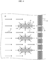
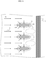
- the communication holes 24 are provided in a wall of the outer cooling passage 19 at positions on the downstream side of center lines X, which extend in the turbine radial directions, of the struts 11 in regard to the flow direction of the combustion gas 7.
- the communication holes 24 are provided on the downstream side of downstream edges 11B of the struts 11; specifically, the communication holes 24 are provided in the flange 20 by which the outer diffuser 10B and the downstream-side diffuser 13 are coupled to each other.
- the outer cooling passage 19 communicates with a space outside the downstream-side diffuser 13, namely, with the outside of gas turbine fluid systems such as systems of a working fluid, cooling air, sealing air, etc.
- the positions of the communication holes 24 are located on the downstream side of the center lines X of the struts 11, and, where the communication holes 24 are disposed on the downstream side of the downstream edges 11B of the struts 11, stagnation regions (which will be detailed later) inside the cooling passage can be thereby reduced.
- a plurality of the communication holes 24 are provided at intervals along the circumferential direction.
- the circumferential pitch of the communication holes 24 is set to be shorter than the circumferential pitch of the struts 11 which cross the outer cooling passage 19, such that at least one communication hole 24 is disposed between each pair of the adjacent struts 11.
- the communication holes 24 are each provided at each of the positions corresponding to the struts 11 and at each middle position between the adjacent struts 11, as viewed in the axial direction of the turbine. While one communication hole 24 is provided between the adjacent struts 11 in this embodiment, a plurality of the communication holes 24 may be provided between the adjacent struts 11. In this case, while the circumferential pitch of the communication holes 24 may be constant, the communication holes 24 may be unevenly distributed along the circumferential direction; for example, the communication holes 24 may be provided such that the circumferential density thereof is higher in the vicinity of the midpoint between the adjacent struts 11 and is lower in the vicinity of the struts 11.
- the opening area of the communication hole 24 is constant in this embodiment, the opening area of the communication hole 24 may be set to vary along the circumferential direction.
- the total opening area of the communication holes 24 is set such that most of the cooling air 23 supplied into the exhaust frame 4 is intercepted by the flange 20, and the flow rate of the cooling air 23 flowing out through the communication holes 24 can be suppressed to such an extent that its influence on gas turbine efficiency is negligible (for example, around 3% based on the total flow rate of the cooling air 23).
- the communication holes 24 are formed in such a manner that they can be closed with plugs or the like, by forming the communication holes 24 as threaded holes, for example.
- the combustion gas 7 produced in the combustor 2 flows into the turbine 3 in the state of a higher pressure (e.g., about 2 MPa) as compared to the atmospheric pressure, is lowered in pressure and temperature while performing a work at each stage of the turbine 3, and passes through the final-stage moving blades 27 to flow into the exhaust passage 18 (see FIG. 2 ).
- the combustion gas 7 at the time of flowing into the exhaust passage 18 has a pressure (e.g., about 0.09 MPa) having been lowered below the atmospheric pressure.
- the combustion gas 7 having flowed into the exhaust passage 18 is reduced in velocity in the process of flowing downstream (toward the outlet side) through the exhaust passage 18, and recovers pressure nearly to the atmospheric pressure.
- the cooling air 23 is an extracted portion of the high-pressure air produced in the compressor 1, and is supplied into the outer cooling passage 19 via the cooling medium supply hole 15 in the state of a high pressure (e.g., about 0.11 MPa). Since the combustion gas 7 flowing into the exhaust passage 18 has a pressure lower than the atmospheric pressure, the cooling air 23 supplied into the outer cooling passage 19 flows through the outer cooling passage 19, the connection passages 22 and the inner cooling passage 16 due to the pressure difference between its pressure and the internal pressure inside the exhaust passage 18, to join the combustion gas 7 flowing through the exhaust passage 18, by way of the final stage wheel space 21.
- a high pressure e.g., about 0.11 MPa
- the cooling air 23 flows along the casing 9, the upstream-side diffuser 10, the struts 11 and the strut covers 12 in a turning-back manner, whereby the casing 9, the upstream-side diffuser 10, the struts 11 and the strut covers 12 are effectively cooled.
- this is not restrictive; for example, other supply source such as a blower can also be used.
- FIG. 7 is a schematic configuration view of an exhaust frame according to a second embodiment.
- the equivalent parts to those in the first embodiment above are denoted by the same reference symbols as used above, and descriptions of them will be omitted appropriately.
- An exhaust frame 104 according to this embodiment differs from the exhaust frame 4 of the first embodiment in the position of communication holes. In other points of configuration, the exhaust frame 104 in this embodiment is the same as the exhaust frame 4 in the first embodiment.
- communication holes 28 are provided in the outer diffuser 10B at positions on the downstream side of the center lines X, which extend in the radial directions of the turbine, of the struts 11 in the flow direction of the combustion gas 7 (in the example illustrated, on the downstream side of downstream edges of the struts 11), and the outer cooling passage 19 communicates with the exhaust passage 18 through the communication holes 28.
- the internal pressure inside the outer cooling passage 19 is higher than the internal pressure inside the exhaust passage 18. Therefore, although the cooling air 23 having reached a downstream-side end portion of the outer cooling passage 19 mostly flows into the connection passages 22, part of the cooling air 23 is sucked into the communication holes 28 to join the combustion gas 7 flowing through the exhaust gas 18. As a result, the flow of the cooling air 23 in the vicinity of downstream edges of the struts 11 in the outer cooling passage 19 is accelerated, so that the flow rate and flow velocity of the cooling air 23 passing along the outer going-around flow path and flowing into the connection passages 22 are increased.
- the cooling air 23 having flowed through the outer cooling passage 19 and having cooled the outer diffuser 10B can be led into the exhaust passage 18, instead of into the space outside of the downstream-side diffuser 13. Therefore, the quantity of heat released to the external space from the gas turbine 100 (a diffusing heat quantity) can be decreased.
- the communication holes 28 are provided in the outer diffuser 10B which is thinner than the flange 20, the communication holes can be provided more easily than in the first embodiment.
- FIG. 8 is a schematic configuration view of an exhaust frame according to a third embodiment.
- the equivalent parts to those in the first embodiment above are denoted by the same reference symbols as used above, and descriptions of them will be omitted appropriately.
- An exhaust frame 204 according to this embodiment differs from the exhaust frame 4 of the first embodiment in the position of communication holes. In other points of configuration, the exhaust frame 204 in this embodiment is the same as the exhaust frame 4 in the first embodiment.
- communication holes 29 are provided in the outer casing 9B at positions on the downstream side of the center lines X, which extend in the radial directions of the turbine, of the struts 11 in the flow direction of the combustion gas 7, and the outer cooling passage 19 communicates with the space outside of the outer casing 9B through the outer casing 9B.
- the cooling air 23 flowing through the outer cooling passage 19 has a pressure higher than the atmospheric pressure whereas the air pressure in the space outside of the outer casing 9B is the atmospheric pressure, the internal pressure inside the outer cooling passage 19 is higher than the air pressure in the space outside of the outer casing 9B. Therefore, although the cooling air 23 having reached a downstream-side end portion of the outer cooling passage 19 mostly flows into the connection passages 22, part of the cooling air 23 is sucked into the communication holes 29. As a result, the flow of the cooling air 23 in the vicinity of downstream edges of the struts 11 in the outer cooling passage 19 is accelerated, so that the flow rate and flow velocity of the cooling air 23 passing along the outer going-around flow path and flowing into the connection passages 22 are increased.
Landscapes
- Engineering & Computer Science (AREA)
- Mechanical Engineering (AREA)
- General Engineering & Computer Science (AREA)
- Chemical & Material Sciences (AREA)
- Combustion & Propulsion (AREA)
- Physics & Mathematics (AREA)
- Fluid Mechanics (AREA)
- Turbine Rotor Nozzle Sealing (AREA)
Claims (7)
- Cadre d'échappement (4) relié à une sortie pour des gaz de combustion (7) d'une turbine (3), le cadre d'échappement (4) comprenant :un boîtier intérieur (9A) ;une paroi circonférentielle intérieure (10A) d'un diffuseur (10) qui couvre un côté extérieur du boîtier intérieur (9A) et qui définit, entre la paroi circonférentielle intérieure (10A) et le boîtier intérieur (9A), un espace de refroidissement intérieur annulaire (16) relié à un espace d'une roue d'étage final (21) de la turbine (3) ;une paroi circonférentielle extérieure (10B) du diffuseur (10) qui couvre un côté extérieur de la paroi circonférentielle intérieure (10A) et qui définit un passage d'échappement (18) pour les gaz de combustion (7) entre la paroi circonférentielle extérieure (10B) et la paroi circonférentielle intérieure (10A) ;un boîtier extérieur (9B) qui couvre un côté extérieur de la paroi circonférentielle extérieure (10B) et qui définit un passage de refroidissement extérieur annulaire (19) entre le boîtier extérieur (9B) et la paroi circonférentielle extérieure (10B) ;une entretoise (11) qui relie le boîtier intérieur (9A) et le boîtier extérieur (9B) l'un à l'autre tout en croisant le passage d'échappement (18) ; etun couvercle d'entretoise (12) qui relie la paroi circonférentielle intérieure (10A) et la paroi circonférentielle extérieure (10B) l'une à l'autre, qui couvre l'entretoise (11), et qui définit, entre le couvercle d'entretoise (12) et l'entretoise (11), un passage de liaison annulaire (22) pour relier le passage de refroidissement intérieur (16) et le passage de refroidissement extérieur (19) l'un à l'autre,dans lequel le passage de refroidissement extérieur (19) est doté d'un trou d'introduction d'air de refroidissement (15) à une position sur un côté amont dans la direction d'écoulement des gaz de combustion (7) par comparaison au passage de liaison (22),caractérisé en ce queun trajet d'écoulement est formé de telle façon que de l'air de refroidissement (23) introduit dans le passage de refroidissement extérieur (19) depuis le trou d'introduction d'air de refroidissement (15) passe à travers le passage de liaison (22) et s'écoule en descendant vers l'espace de roue d'étage final (21) depuis une sortie du passage de refroidissement intérieur (16), etcaractérisé en outre en ce que le cadre d'échappement (4) comprend :
un trou de communication (24 ; 28 ; 29) prévu dans une paroi du passage de refroidissement extérieur (19) à une position sur un côté aval d'une ligne centrale (X) de l'entretoise (11) dans une direction d'écoulement des gaz de combustion (7), le trou de communication (24 ; 28 ; 29) étant configuré pour permettre à une partie de l'air de refroidissement dans le passage de refroidissement extérieur (19) qui s'écoule depuis le trou d'introduction d'air de refroidissement (15) vers une entrée du passage de liaison (22) de s'écouler hors du passage de refroidissement extérieur (19). - Cadre d'échappement (4) selon la revendication 1,
dans lequel le trou de communication (24 ; 28 ; 29) est prévu à une position sur le côté aval d'un bord aval de l'entretoise (11). - Cadre d'échappement (4) selon la revendication 1,
comprenant en outre un diffuseur du côté aval (13), relié à la paroi circonférentielle extérieure (10B) à une position sur le côté aval dans la direction d'écoulement des gaz de combustion (7),
dans lequel une portion terminale du passage de refroidissement extérieur (19) est fermée avec une bride (20) pour la paroi circonférentielle extérieure (10B) et le diffuseur côté aval (13) qui sont reliés l'un à l'autre, et
le trou de communication (24) est prévu dans la bride (20) de telle façon que le passage de refroidissement extérieur (19) communique avec un espace à l'extérieur du diffuseur côté aval (13) à travers la bride (20). - Cadre d'échappement (4) selon la revendication 1,
dans lequel le trou de communication (28) est prévu dans la paroi circonférentielle extérieure (10B) de telle façon que le passage de refroidissement extérieur (19) communique avec le passage d'échappement (18) à travers la paroi circonférentielle extérieure (10B). - Cadre d'échappement (4) selon la revendication 1,
dans lequel le trou de communication (29) est prévu dans le boîtier extérieur (9B) de telle façon que le passage de refroidissement extérieur (19) communique avec un espace à l'extérieur du boîtier extérieur (9B) à travers le boîtier extérieur (9B). - Cadre d'échappement (4) selon la revendication 1,
dans lequel une pluralité d'entretoises (11) sont prévues le long de la direction circonférentielle du boîtier intérieur (9A), et
l'un au moins des trous de communication (24 ; 28 ; 29) est prévu entre chaque paire d'entretoises adjacentes (11). - Cadre d'échappement (4) selon la revendication 1,
dans lequel le trou de communication (24 ; 28 ; 29) est un trou taraudé configuré pour être fermé avec un bouchon.
Applications Claiming Priority (1)
| Application Number | Priority Date | Filing Date | Title |
|---|---|---|---|
| JP2016011010A JP6580494B2 (ja) | 2016-01-22 | 2016-01-22 | 排気フレーム |
Publications (2)
| Publication Number | Publication Date |
|---|---|
| EP3196422A1 EP3196422A1 (fr) | 2017-07-26 |
| EP3196422B1 true EP3196422B1 (fr) | 2019-12-18 |
Family
ID=57881990
Family Applications (1)
| Application Number | Title | Priority Date | Filing Date |
|---|---|---|---|
| EP17152469.7A Active EP3196422B1 (fr) | 2016-01-22 | 2017-01-20 | Cadre d'échappement |
Country Status (5)
| Country | Link |
|---|---|
| US (1) | US10422249B2 (fr) |
| EP (1) | EP3196422B1 (fr) |
| JP (1) | JP6580494B2 (fr) |
| KR (1) | KR101981379B1 (fr) |
| CN (1) | CN106996321B (fr) |
Families Citing this family (4)
| Publication number | Priority date | Publication date | Assignee | Title |
|---|---|---|---|---|
| US10837316B2 (en) * | 2017-08-25 | 2020-11-17 | DOOSAN Heavy Industries Construction Co., LTD | High thermal response exhaust diffuser strut collar |
| GB2566498B (en) * | 2017-09-15 | 2021-02-17 | Gkn Aerospace Sweden Ab | Turbine exhaust case cooling |
| CN107524524A (zh) * | 2017-10-24 | 2017-12-29 | 江苏华强新能源科技有限公司 | 一种高效燃气轮机排气系统 |
| KR102403823B1 (ko) * | 2019-12-13 | 2022-05-30 | 두산에너빌리티 주식회사 | 스트립이 형성된 배기 디퓨져의 스트롯 구조 및 가스터빈 |
Family Cites Families (14)
| Publication number | Priority date | Publication date | Assignee | Title |
|---|---|---|---|---|
| US3631672A (en) * | 1969-08-04 | 1972-01-04 | Gen Electric | Eductor cooled gas turbine casing |
| JPS59173527A (ja) * | 1983-03-22 | 1984-10-01 | Hitachi Ltd | ガスタ−ビン排気フレ−ム冷却空気系統 |
| US6638013B2 (en) * | 2002-02-25 | 2003-10-28 | Honeywell International Inc. | Thermally isolated housing in gas turbine engine |
| JP4040556B2 (ja) * | 2003-09-04 | 2008-01-30 | 株式会社日立製作所 | ガスタービン設備及び冷却空気供給方法 |
| US7493769B2 (en) * | 2005-10-25 | 2009-02-24 | General Electric Company | Assembly and method for cooling rear bearing and exhaust frame of gas turbine |
| JP5118496B2 (ja) * | 2008-01-10 | 2013-01-16 | 三菱重工業株式会社 | ガスタービンの排気部の構造およびガスタービン |
| PL220729B1 (pl) * | 2011-10-03 | 2015-12-31 | Gen Electric | Układ turbiny gazowej |
| US8756911B1 (en) * | 2011-11-16 | 2014-06-24 | Florida Turbine Technologies, Inc. | Turbine exhaust cylinder and strut cooling |
| US10094285B2 (en) * | 2011-12-08 | 2018-10-09 | Siemens Aktiengesellschaft | Gas turbine outer case active ambient cooling including air exhaust into sub-ambient cavity |
| JP5646109B2 (ja) * | 2012-02-27 | 2014-12-24 | 三菱日立パワーシステムズ株式会社 | ガスタービン |
| US9611756B2 (en) * | 2012-11-02 | 2017-04-04 | General Electric Company | System and method for protecting components in a gas turbine engine with exhaust gas recirculation |
| US9206742B2 (en) * | 2012-12-29 | 2015-12-08 | United Technologies Corporation | Passages to facilitate a secondary flow between components |
| US20150354382A1 (en) * | 2014-06-06 | 2015-12-10 | General Electric Company | Exhaust frame cooling via strut cooling passages |
| JP6399894B2 (ja) * | 2014-10-29 | 2018-10-03 | 三菱日立パワーシステムズ株式会社 | 排気装置及びガスタービン |
-
2016
- 2016-01-22 JP JP2016011010A patent/JP6580494B2/ja active Active
-
2017
- 2017-01-16 KR KR1020170006919A patent/KR101981379B1/ko active IP Right Grant
- 2017-01-18 US US15/408,805 patent/US10422249B2/en active Active
- 2017-01-19 CN CN201710037420.0A patent/CN106996321B/zh active Active
- 2017-01-20 EP EP17152469.7A patent/EP3196422B1/fr active Active
Non-Patent Citations (1)
| Title |
|---|
| None * |
Also Published As
| Publication number | Publication date |
|---|---|
| JP6580494B2 (ja) | 2019-09-25 |
| JP2017129107A (ja) | 2017-07-27 |
| US20170211424A1 (en) | 2017-07-27 |
| CN106996321B (zh) | 2020-01-07 |
| CN106996321A (zh) | 2017-08-01 |
| KR20170088296A (ko) | 2017-08-01 |
| US10422249B2 (en) | 2019-09-24 |
| EP3196422A1 (fr) | 2017-07-26 |
| KR101981379B1 (ko) | 2019-05-22 |
Similar Documents
| Publication | Publication Date | Title |
|---|---|---|
| US20200277862A1 (en) | Airfoil for a turbine engine | |
| US8087249B2 (en) | Turbine cooling air from a centrifugal compressor | |
| US20170248155A1 (en) | Centrifugal compressor diffuser passage boundary layer control | |
| JP5507828B2 (ja) | 非対称流れ抽出システム | |
| JP6399894B2 (ja) | 排気装置及びガスタービン | |
| JP2017025911A (ja) | ガスタービンエンジン用のシュラウドアセンブリ | |
| US20130098061A1 (en) | Gas turbine engine cooling systems having hub-bleed impellers and methods for the production thereof | |
| EP3196422B1 (fr) | Cadre d'échappement | |
| US10815789B2 (en) | Impingement holes for a turbine engine component | |
| JP2017072128A (ja) | ステータ部品 | |
| JP2016205383A (ja) | ガスタービンエンジン用のシュラウドアセンブリ及びシュラウド | |
| JP2012013080A (ja) | ガスタービンエンジンに用いるロータ組立体、およびそれを組み立てる方法 | |
| US20160123186A1 (en) | Shroud assembly for a turbine engine | |
| US11391176B2 (en) | Method and apparatus for supplying cooling air to a turbine | |
| US20190218925A1 (en) | Turbine engine shroud | |
| US20190170001A1 (en) | Impingement cooling of a blade platform | |
| WO2015156200A1 (fr) | Structure de ventilation de turbine | |
| US20170030218A1 (en) | Turbine vane rear insert scheme | |
| US10563518B2 (en) | Gas turbine engine trailing edge ejection holes | |
| EP2971665B1 (fr) | Diviseur pour collecteur de prélèvement d'air | |
| US10280785B2 (en) | Shroud assembly for a turbine engine | |
| CN106545364B (zh) | 用于涡轮叶轮空间冷却的混合室 | |
| US10808572B2 (en) | Cooling structure for a turbomachinery component | |
| US20140260292A1 (en) | Gas turbine and method for guiding compressed fluid in a gas turbine | |
| US11585228B2 (en) | Technique for cooling inner shroud of a gas turbine vane |
Legal Events
| Date | Code | Title | Description |
|---|---|---|---|
| PUAI | Public reference made under article 153(3) epc to a published international application that has entered the european phase |
Free format text: ORIGINAL CODE: 0009012 |
|
| STAA | Information on the status of an ep patent application or granted ep patent |
Free format text: STATUS: REQUEST FOR EXAMINATION WAS MADE |
|
| 17P | Request for examination filed |
Effective date: 20170126 |
|
| AK | Designated contracting states |
Kind code of ref document: A1 Designated state(s): AL AT BE BG CH CY CZ DE DK EE ES FI FR GB GR HR HU IE IS IT LI LT LU LV MC MK MT NL NO PL PT RO RS SE SI SK SM TR |
|
| AX | Request for extension of the european patent |
Extension state: BA ME |
|
| RIN1 | Information on inventor provided before grant (corrected) |
Inventor name: KAWAI, RYO Inventor name: NAKAMURA, TETSUYA Inventor name: TAKEDA, TAKUYA Inventor name: NANATAKI, KENJI |
|
| GRAP | Despatch of communication of intention to grant a patent |
Free format text: ORIGINAL CODE: EPIDOSNIGR1 |
|
| STAA | Information on the status of an ep patent application or granted ep patent |
Free format text: STATUS: GRANT OF PATENT IS INTENDED |
|
| RIC1 | Information provided on ipc code assigned before grant |
Ipc: F01D 25/30 20060101ALI20190625BHEP Ipc: F01D 25/14 20060101ALI20190625BHEP Ipc: F01D 25/12 20060101AFI20190625BHEP Ipc: F01D 9/06 20060101ALI20190625BHEP |
|
| INTG | Intention to grant announced |
Effective date: 20190717 |
|
| GRAS | Grant fee paid |
Free format text: ORIGINAL CODE: EPIDOSNIGR3 |
|
| GRAA | (expected) grant |
Free format text: ORIGINAL CODE: 0009210 |
|
| STAA | Information on the status of an ep patent application or granted ep patent |
Free format text: STATUS: THE PATENT HAS BEEN GRANTED |
|
| RIN1 | Information on inventor provided before grant (corrected) |
Inventor name: NANATAKI, KENJI Inventor name: NAKAMURA, TETSUYA Inventor name: TAKEDA, TAKUYA Inventor name: KAWAI, RYO |
|
| AK | Designated contracting states |
Kind code of ref document: B1 Designated state(s): AL AT BE BG CH CY CZ DE DK EE ES FI FR GB GR HR HU IE IS IT LI LT LU LV MC MK MT NL NO PL PT RO RS SE SI SK SM TR |
|
| REG | Reference to a national code |
Ref country code: CH Ref legal event code: EP |
|
| REG | Reference to a national code |
Ref country code: DE Ref legal event code: R096 Ref document number: 602017009706 Country of ref document: DE |
|
| REG | Reference to a national code |
Ref country code: IE Ref legal event code: FG4D |
|
| REG | Reference to a national code |
Ref country code: AT Ref legal event code: REF Ref document number: 1214824 Country of ref document: AT Kind code of ref document: T Effective date: 20200115 |
|
| REG | Reference to a national code |
Ref country code: NL Ref legal event code: MP Effective date: 20191218 |
|
| PG25 | Lapsed in a contracting state [announced via postgrant information from national office to epo] |
Ref country code: LT Free format text: LAPSE BECAUSE OF FAILURE TO SUBMIT A TRANSLATION OF THE DESCRIPTION OR TO PAY THE FEE WITHIN THE PRESCRIBED TIME-LIMIT Effective date: 20191218 Ref country code: NO Free format text: LAPSE BECAUSE OF FAILURE TO SUBMIT A TRANSLATION OF THE DESCRIPTION OR TO PAY THE FEE WITHIN THE PRESCRIBED TIME-LIMIT Effective date: 20200318 Ref country code: GR Free format text: LAPSE BECAUSE OF FAILURE TO SUBMIT A TRANSLATION OF THE DESCRIPTION OR TO PAY THE FEE WITHIN THE PRESCRIBED TIME-LIMIT Effective date: 20200319 Ref country code: SE Free format text: LAPSE BECAUSE OF FAILURE TO SUBMIT A TRANSLATION OF THE DESCRIPTION OR TO PAY THE FEE WITHIN THE PRESCRIBED TIME-LIMIT Effective date: 20191218 Ref country code: LV Free format text: LAPSE BECAUSE OF FAILURE TO SUBMIT A TRANSLATION OF THE DESCRIPTION OR TO PAY THE FEE WITHIN THE PRESCRIBED TIME-LIMIT Effective date: 20191218 Ref country code: BG Free format text: LAPSE BECAUSE OF FAILURE TO SUBMIT A TRANSLATION OF THE DESCRIPTION OR TO PAY THE FEE WITHIN THE PRESCRIBED TIME-LIMIT Effective date: 20200318 Ref country code: FI Free format text: LAPSE BECAUSE OF FAILURE TO SUBMIT A TRANSLATION OF THE DESCRIPTION OR TO PAY THE FEE WITHIN THE PRESCRIBED TIME-LIMIT Effective date: 20191218 |
|
| REG | Reference to a national code |
Ref country code: LT Ref legal event code: MG4D |
|
| PG25 | Lapsed in a contracting state [announced via postgrant information from national office to epo] |
Ref country code: RS Free format text: LAPSE BECAUSE OF FAILURE TO SUBMIT A TRANSLATION OF THE DESCRIPTION OR TO PAY THE FEE WITHIN THE PRESCRIBED TIME-LIMIT Effective date: 20191218 Ref country code: HR Free format text: LAPSE BECAUSE OF FAILURE TO SUBMIT A TRANSLATION OF THE DESCRIPTION OR TO PAY THE FEE WITHIN THE PRESCRIBED TIME-LIMIT Effective date: 20191218 |
|
| PG25 | Lapsed in a contracting state [announced via postgrant information from national office to epo] |
Ref country code: AL Free format text: LAPSE BECAUSE OF FAILURE TO SUBMIT A TRANSLATION OF THE DESCRIPTION OR TO PAY THE FEE WITHIN THE PRESCRIBED TIME-LIMIT Effective date: 20191218 |
|
| PG25 | Lapsed in a contracting state [announced via postgrant information from national office to epo] |
Ref country code: CZ Free format text: LAPSE BECAUSE OF FAILURE TO SUBMIT A TRANSLATION OF THE DESCRIPTION OR TO PAY THE FEE WITHIN THE PRESCRIBED TIME-LIMIT Effective date: 20191218 Ref country code: NL Free format text: LAPSE BECAUSE OF FAILURE TO SUBMIT A TRANSLATION OF THE DESCRIPTION OR TO PAY THE FEE WITHIN THE PRESCRIBED TIME-LIMIT Effective date: 20191218 Ref country code: EE Free format text: LAPSE BECAUSE OF FAILURE TO SUBMIT A TRANSLATION OF THE DESCRIPTION OR TO PAY THE FEE WITHIN THE PRESCRIBED TIME-LIMIT Effective date: 20191218 Ref country code: RO Free format text: LAPSE BECAUSE OF FAILURE TO SUBMIT A TRANSLATION OF THE DESCRIPTION OR TO PAY THE FEE WITHIN THE PRESCRIBED TIME-LIMIT Effective date: 20191218 Ref country code: PT Free format text: LAPSE BECAUSE OF FAILURE TO SUBMIT A TRANSLATION OF THE DESCRIPTION OR TO PAY THE FEE WITHIN THE PRESCRIBED TIME-LIMIT Effective date: 20200513 |
|
| PG25 | Lapsed in a contracting state [announced via postgrant information from national office to epo] |
Ref country code: SM Free format text: LAPSE BECAUSE OF FAILURE TO SUBMIT A TRANSLATION OF THE DESCRIPTION OR TO PAY THE FEE WITHIN THE PRESCRIBED TIME-LIMIT Effective date: 20191218 Ref country code: IS Free format text: LAPSE BECAUSE OF FAILURE TO SUBMIT A TRANSLATION OF THE DESCRIPTION OR TO PAY THE FEE WITHIN THE PRESCRIBED TIME-LIMIT Effective date: 20200418 Ref country code: SK Free format text: LAPSE BECAUSE OF FAILURE TO SUBMIT A TRANSLATION OF THE DESCRIPTION OR TO PAY THE FEE WITHIN THE PRESCRIBED TIME-LIMIT Effective date: 20191218 |
|
| REG | Reference to a national code |
Ref country code: CH Ref legal event code: PL |
|
| REG | Reference to a national code |
Ref country code: DE Ref legal event code: R097 Ref document number: 602017009706 Country of ref document: DE |
|
| PG25 | Lapsed in a contracting state [announced via postgrant information from national office to epo] |
Ref country code: MC Free format text: LAPSE BECAUSE OF FAILURE TO SUBMIT A TRANSLATION OF THE DESCRIPTION OR TO PAY THE FEE WITHIN THE PRESCRIBED TIME-LIMIT Effective date: 20191218 |
|
| REG | Reference to a national code |
Ref country code: AT Ref legal event code: MK05 Ref document number: 1214824 Country of ref document: AT Kind code of ref document: T Effective date: 20191218 Ref country code: BE Ref legal event code: MM Effective date: 20200131 |
|
| PLBE | No opposition filed within time limit |
Free format text: ORIGINAL CODE: 0009261 |
|
| STAA | Information on the status of an ep patent application or granted ep patent |
Free format text: STATUS: NO OPPOSITION FILED WITHIN TIME LIMIT |
|
| PG25 | Lapsed in a contracting state [announced via postgrant information from national office to epo] |
Ref country code: ES Free format text: LAPSE BECAUSE OF FAILURE TO SUBMIT A TRANSLATION OF THE DESCRIPTION OR TO PAY THE FEE WITHIN THE PRESCRIBED TIME-LIMIT Effective date: 20191218 Ref country code: LU Free format text: LAPSE BECAUSE OF NON-PAYMENT OF DUE FEES Effective date: 20200120 Ref country code: DK Free format text: LAPSE BECAUSE OF FAILURE TO SUBMIT A TRANSLATION OF THE DESCRIPTION OR TO PAY THE FEE WITHIN THE PRESCRIBED TIME-LIMIT Effective date: 20191218 |
|
| 26N | No opposition filed |
Effective date: 20200921 |
|
| PG25 | Lapsed in a contracting state [announced via postgrant information from national office to epo] |
Ref country code: SI Free format text: LAPSE BECAUSE OF FAILURE TO SUBMIT A TRANSLATION OF THE DESCRIPTION OR TO PAY THE FEE WITHIN THE PRESCRIBED TIME-LIMIT Effective date: 20191218 Ref country code: LI Free format text: LAPSE BECAUSE OF NON-PAYMENT OF DUE FEES Effective date: 20200131 Ref country code: AT Free format text: LAPSE BECAUSE OF FAILURE TO SUBMIT A TRANSLATION OF THE DESCRIPTION OR TO PAY THE FEE WITHIN THE PRESCRIBED TIME-LIMIT Effective date: 20191218 Ref country code: CH Free format text: LAPSE BECAUSE OF NON-PAYMENT OF DUE FEES Effective date: 20200131 Ref country code: BE Free format text: LAPSE BECAUSE OF NON-PAYMENT OF DUE FEES Effective date: 20200131 |
|
| REG | Reference to a national code |
Ref country code: DE Ref legal event code: R082 Ref document number: 602017009706 Country of ref document: DE Representative=s name: MERH-IP MATIAS ERNY REICHL HOFFMANN PATENTANWA, DE Ref country code: DE Ref legal event code: R081 Ref document number: 602017009706 Country of ref document: DE Owner name: MITSUBISHI POWER, LTD., JP Free format text: FORMER OWNER: MITSUBISHI HITACHI POWER SYSTEMS, LTD., YOKOHAMA, KANAGAWA, JP |
|
| PG25 | Lapsed in a contracting state [announced via postgrant information from national office to epo] |
Ref country code: IE Free format text: LAPSE BECAUSE OF NON-PAYMENT OF DUE FEES Effective date: 20200120 Ref country code: IT Free format text: LAPSE BECAUSE OF FAILURE TO SUBMIT A TRANSLATION OF THE DESCRIPTION OR TO PAY THE FEE WITHIN THE PRESCRIBED TIME-LIMIT Effective date: 20191218 |
|
| PG25 | Lapsed in a contracting state [announced via postgrant information from national office to epo] |
Ref country code: PL Free format text: LAPSE BECAUSE OF FAILURE TO SUBMIT A TRANSLATION OF THE DESCRIPTION OR TO PAY THE FEE WITHIN THE PRESCRIBED TIME-LIMIT Effective date: 20191218 |
|
| PG25 | Lapsed in a contracting state [announced via postgrant information from national office to epo] |
Ref country code: TR Free format text: LAPSE BECAUSE OF FAILURE TO SUBMIT A TRANSLATION OF THE DESCRIPTION OR TO PAY THE FEE WITHIN THE PRESCRIBED TIME-LIMIT Effective date: 20191218 Ref country code: MT Free format text: LAPSE BECAUSE OF FAILURE TO SUBMIT A TRANSLATION OF THE DESCRIPTION OR TO PAY THE FEE WITHIN THE PRESCRIBED TIME-LIMIT Effective date: 20191218 Ref country code: CY Free format text: LAPSE BECAUSE OF FAILURE TO SUBMIT A TRANSLATION OF THE DESCRIPTION OR TO PAY THE FEE WITHIN THE PRESCRIBED TIME-LIMIT Effective date: 20191218 |
|
| PG25 | Lapsed in a contracting state [announced via postgrant information from national office to epo] |
Ref country code: MK Free format text: LAPSE BECAUSE OF FAILURE TO SUBMIT A TRANSLATION OF THE DESCRIPTION OR TO PAY THE FEE WITHIN THE PRESCRIBED TIME-LIMIT Effective date: 20191218 |
|
| PGFP | Annual fee paid to national office [announced via postgrant information from national office to epo] |
Ref country code: GB Payment date: 20231130 Year of fee payment: 8 |
|
| PGFP | Annual fee paid to national office [announced via postgrant information from national office to epo] |
Ref country code: FR Payment date: 20231212 Year of fee payment: 8 |
|
| PGFP | Annual fee paid to national office [announced via postgrant information from national office to epo] |
Ref country code: DE Payment date: 20231128 Year of fee payment: 8 |