EP3193720B1 - Systems and methods for grating modulation of spectra and intensity in computed tomography - Google Patents
Systems and methods for grating modulation of spectra and intensity in computed tomography Download PDFInfo
- Publication number
- EP3193720B1 EP3193720B1 EP15767593.5A EP15767593A EP3193720B1 EP 3193720 B1 EP3193720 B1 EP 3193720B1 EP 15767593 A EP15767593 A EP 15767593A EP 3193720 B1 EP3193720 B1 EP 3193720B1
- Authority
- EP
- European Patent Office
- Prior art keywords
- ray
- filter
- pixels
- imaging system
- grating
- Prior art date
- Legal status (The legal status is an assumption and is not a legal conclusion. Google has not performed a legal analysis and makes no representation as to the accuracy of the status listed.)
- Active
Links
Images

Classifications
-
- A—HUMAN NECESSITIES
- A61—MEDICAL OR VETERINARY SCIENCE; HYGIENE
- A61B—DIAGNOSIS; SURGERY; IDENTIFICATION
- A61B6/00—Apparatus or devices for radiation diagnosis; Apparatus or devices for radiation diagnosis combined with radiation therapy equipment
- A61B6/02—Arrangements for diagnosis sequentially in different planes; Stereoscopic radiation diagnosis
- A61B6/03—Computed tomography [CT]
- A61B6/032—Transmission computed tomography [CT]
-
- A—HUMAN NECESSITIES
- A61—MEDICAL OR VETERINARY SCIENCE; HYGIENE
- A61B—DIAGNOSIS; SURGERY; IDENTIFICATION
- A61B6/00—Apparatus or devices for radiation diagnosis; Apparatus or devices for radiation diagnosis combined with radiation therapy equipment
- A61B6/06—Diaphragms
-
- A—HUMAN NECESSITIES
- A61—MEDICAL OR VETERINARY SCIENCE; HYGIENE
- A61B—DIAGNOSIS; SURGERY; IDENTIFICATION
- A61B6/00—Apparatus or devices for radiation diagnosis; Apparatus or devices for radiation diagnosis combined with radiation therapy equipment
- A61B6/40—Arrangements for generating radiation specially adapted for radiation diagnosis
- A61B6/4007—Arrangements for generating radiation specially adapted for radiation diagnosis characterised by using a plurality of source units
-
- A—HUMAN NECESSITIES
- A61—MEDICAL OR VETERINARY SCIENCE; HYGIENE
- A61B—DIAGNOSIS; SURGERY; IDENTIFICATION
- A61B6/00—Apparatus or devices for radiation diagnosis; Apparatus or devices for radiation diagnosis combined with radiation therapy equipment
- A61B6/40—Arrangements for generating radiation specially adapted for radiation diagnosis
- A61B6/4021—Arrangements for generating radiation specially adapted for radiation diagnosis involving movement of the focal spot
-
- A—HUMAN NECESSITIES
- A61—MEDICAL OR VETERINARY SCIENCE; HYGIENE
- A61B—DIAGNOSIS; SURGERY; IDENTIFICATION
- A61B6/00—Apparatus or devices for radiation diagnosis; Apparatus or devices for radiation diagnosis combined with radiation therapy equipment
- A61B6/40—Arrangements for generating radiation specially adapted for radiation diagnosis
- A61B6/4035—Arrangements for generating radiation specially adapted for radiation diagnosis the source being combined with a filter or grating
-
- A—HUMAN NECESSITIES
- A61—MEDICAL OR VETERINARY SCIENCE; HYGIENE
- A61B—DIAGNOSIS; SURGERY; IDENTIFICATION
- A61B6/00—Apparatus or devices for radiation diagnosis; Apparatus or devices for radiation diagnosis combined with radiation therapy equipment
- A61B6/48—Diagnostic techniques
- A61B6/482—Diagnostic techniques involving multiple energy imaging
-
- G—PHYSICS
- G01—MEASURING; TESTING
- G01N—INVESTIGATING OR ANALYSING MATERIALS BY DETERMINING THEIR CHEMICAL OR PHYSICAL PROPERTIES
- G01N23/00—Investigating or analysing materials by the use of wave or particle radiation, e.g. X-rays or neutrons, not covered by groups G01N3/00 – G01N17/00, G01N21/00 or G01N22/00
- G01N23/02—Investigating or analysing materials by the use of wave or particle radiation, e.g. X-rays or neutrons, not covered by groups G01N3/00 – G01N17/00, G01N21/00 or G01N22/00 by transmitting the radiation through the material
- G01N23/06—Investigating or analysing materials by the use of wave or particle radiation, e.g. X-rays or neutrons, not covered by groups G01N3/00 – G01N17/00, G01N21/00 or G01N22/00 by transmitting the radiation through the material and measuring the absorption
- G01N23/083—Investigating or analysing materials by the use of wave or particle radiation, e.g. X-rays or neutrons, not covered by groups G01N3/00 – G01N17/00, G01N21/00 or G01N22/00 by transmitting the radiation through the material and measuring the absorption the radiation being X-rays
- G01N23/087—Investigating or analysing materials by the use of wave or particle radiation, e.g. X-rays or neutrons, not covered by groups G01N3/00 – G01N17/00, G01N21/00 or G01N22/00 by transmitting the radiation through the material and measuring the absorption the radiation being X-rays using polyenergetic X-rays
-
- G—PHYSICS
- G21—NUCLEAR PHYSICS; NUCLEAR ENGINEERING
- G21K—HANDLING OF PARTICLES OR IONISING RADIATION NOT OTHERWISE PROVIDED FOR; IRRADIATION DEVICES; GAMMA RAY OR X-RAY MICROSCOPES
- G21K1/00—Arrangements for handling particles or ionising radiation, e.g. focusing or moderating
- G21K1/10—Scattering devices; Absorbing devices; Ionising radiation filters
-
- G—PHYSICS
- G01—MEASURING; TESTING
- G01N—INVESTIGATING OR ANALYSING MATERIALS BY DETERMINING THEIR CHEMICAL OR PHYSICAL PROPERTIES
- G01N2223/00—Investigating materials by wave or particle radiation
- G01N2223/40—Imaging
- G01N2223/419—Imaging computed tomograph
Definitions
- the present disclosure relates to a method and an imaging system for generating spectrally different X-ray images with an X-ray source and an X-ray detector. More particularly, the present disclosure relates to including a filter providing different spectral filtration within an X-ray system in order to produce a spectrally modulated beam such that neighboring pixels of the X-ray detector receive different spectra, and using this spectral information to perform means of spectral X-ray imaging.
- Computed tomography is the science of recovering a three-dimensional representation of a patient or object by utilizing projection views with different orientations. From this volume, e.g., two-dimensional cross-sectional images can be displayed.
- CT systems typically include an X-ray source collimated to form a cone beam directed through an object to be imaged, i.e., a patient, and received by an X-ray detector array.
- the X-ray source, the cone beam, and the detector array may be rotated together on a gantry within the imaging plane, around the imaged object.
- an unwanted effect may be the radiation dose that a patient receives, as it may induce damage to cells and genes.
- the interaction of X-ray radiation with matter imposes scattered X-ray radiation, which adds in the detector to the signal of interest, i.e., the signal of the primary radiation.
- measures are taken to limit the amount of total X-ray exposure to a minimum, which is required to acquire images.
- a collimator defines a cone shape such that the cone beam covers exactly the whole detector area in order that each detector imaging element (denoted herein as a "pixel”) is exposed to the beam, but the overlap to the non-detector area is reduced to a minimum.
- a bowtie-shaped device known as a "beam shaper,” “bow tie” or sometimes also as a “wedge,” is placed in the path of the X-ray beam.
- the wedge functioning as an X-ray attenuation filter, is generally made of a light metal, such as aluminum, or a synthetic polymer, such as Teflon, having an X-ray absorption spectral characteristic near that of water, and, hence, the human body.
- the wedge is intended to compensate for the variation in thickness of the imaged body.
- the X-rays that pass through the center of the imaged body, normally the thickest part, are least attenuated by this filter, whereas the X-rays that pass through the periphery of the imaged body, normally the thinnest part, are more attenuated by this filter.
- the result of this selective attenuation is a better distribution of the X-ray dose.
- a spatially homogeneous filter (typically in the form of a metal plate, e.g., made of copper) is induced to absorb mainly the low energy components of the spectrum.
- the low energy components of the plain X-ray spectrum are typically that strongly attenuated by an object or a patient that they do not significantly contribute to a measured signal.
- the filter reduces the total dose a patient is exposed to with an acceptable reduction of the acquired detector signal.
- spectral methods commonly termed as dual energy CT, multi-energy CT, or spectral CT.
- the common characteristic of all these methods is that they take use of the fact that different materials attenuate X-rays differently with respect to the energy of the X-ray photons. Consequently, the acquisition of CT projections with different weightings put on the X-ray photon energies provides additional (3D) information, not only of the material density, but also of the chemical composition.
- 3D 3D
- an X-ray imaging system is presented as defined in claim 1.
- the X-ray device includes a collimator positioned between the X-ray device and the filter, the collimator having a plurality of openings for directing the plurality of X-ray beams generated by the X-ray source.
- the X-ray source includes an X-ray emission area with a spatially modulated X-ray intensity profile such that the plurality of X-ray beams originate from one or more pronounced intensity maxima of the X-ray emission area.
- the plurality of pixels have X-ray insensitive regions therebetween.
- the X-ray imaging system and the collimator are configured to reduce X-ray intensity in the X-ray insensitive regions between the plurality of pixels.
- the filter includes at least two different materials.
- one of the filter materials is air.
- the filter includes one material having a spatial modulation.
- the filter is a combination of at least two spatially separated filters.
- the filter has a spatially alternating pattern of spectral filtration.
- the filter is a grating having grating lines or a pattern of tiles representing different spectral filtration.
- the filter is replaceable and can be chosen from a set of a plurality of different filters.
- the subsets of pixels of the X-ray detector form an interlacing and alternating pattern of rows, columns, or tiles.
- a smallest effective size of a row, a column, or a tile of the alternating pattern of a subset of pixels of the X-ray detector corresponds to the effective size of one pixel.
- a method for measuring an intensity of scattered X-ray radiation for at least one pixel subset of an X-ray imaging system as described above including generating a plurality of X-ray beams via the X-ray device, transmitting the plurality of X-ray beams through a combination of one or more filters and collimators, as well as an object included in the X-ray imaging system, and detecting the scattered X-ray intensity for at least one pixel subset representing an opaque filtration of direct X-ray radiation from the X-ray device.
- a method for generating at least one X-ray projection data set including at least two subsets of spectrally different X-ray projections with an X-ray imaging system including generating a plurality of X-ray beams via the X-ray device, transmitting the plurality of X-ray beams through a combination of one or more filters and collimators, as well as an object included in the X-ray imaging system, detecting the X-ray beams via the X-ray detector of the X-ray imaging system, and logically assigning the acquired data of the pixel subsets of the plurality of pixels of the X-ray detector to subsets of spectrally different X-ray projections.
- the present disclosure relates to an x-ray device, particularly in the form of a Computed Tomography (CT) scanner, which includes at least a radiation source, a beam filter, and a radiation-sensitive detector array, described below.
- CT Computed Tomography
- spectral CT imaging may be seen in a device which provides different X-ray spectra for particular pixels.
- each point emitter projects the filter array onto the detector, such that the overlay of each particular image (using the periodicity of the arrays) produces a congruently superposed image of the filtered array.
- a system and method is suggested that includes introducing a filter which spatially and spectrally modulates the X-ray beam.
- This filter may be, for example, constructed from two different materials within an X-ray system in order to produce a spectrally modulated beam such that, for example, neighboring pixels of the X-ray detector receive different spectra.
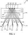
- FIG. 1 an imaging geometry of an imaging system having at least one X-ray source, according to the present disclosure is presented.
- the X-ray imaging system 100 includes at least one X-ray device 110 emitting X-rays from a number of locations 106, a filter grating 120, an optional collimator grating 130, an object space 140, and an X-ray detector 150 including an array of a plurality of pixels 151 to 155, which may be separated by X-ray insensitive gaps 170.
- the X-ray device 110 generates a plurality of X-ray beams 104, each beam 104 characterized by connecting one of the locations 106 with one of the pixels 151 to 155, respectively.
- the X-ray beams 104 pass through a filter 120.
- the filter 120 may be referred to as a "filter grating" configured to apply a specific filtration to each of the X-ray beams 104.
- Locations 106, filter grating 120, and detector pixels 151 to 155 are configured such that all X-ray beams 104 connected to a particular single pixel undergo the same spectral filtration by filter grating 120.
- the spectral and also spatial separation of X-ray beams 104 may be supported by an optional collimator grating 130 which includes a plurality of openings 108.
- the openings 108 are configured such that they allow for the passage of photons propagating along the center of each of the X-ray beams 104, or stated differently, each photon propagating from the center of a location 106 to the center of any pixel 151 to 155 passes an opening 108 of the optional collimator grating 130.
- blockings 131 of the optional collimator 130 are configured to suppress to a maximum amount of X-ray photons, which propagate from one of the locations 106 towards the gaps 170 in between the pixels 151 to 155.
- Not illuminating the pixel gaps 170 means that an object or patient placed in the object space 140 receives less dose compared to a configuration in which the optional collimator grating 130 is not present. For ideal opaque gratings, even a total shadowing of the pixel gaps 170 can be achieved. It can be shown that the dose saving is about 20% for current CT geometries. It is contemplated that the collimator grating 130 is constructed or formed from highly opaque materials, such as, for example, Tungsten or Lead of appropriate thickness, such that the amount of transmitted radiation through the blockings 131 is reduced to a minimum.
- An object to be imaged is positioned in the object space 140 located (from the viewpoint of the X-ray source) behind the filter grating 120 and the optional collimator 130, but before the X-ray detector 150.
- the object space 140 located (from the viewpoint of the X-ray source) behind the filter grating 120 and the optional collimator 130, but before the X-ray detector 150.
- five pixels 151 to 155 are shown. However, one skilled in the art may envision several more pixels forming the array of the X-ray detector 150.
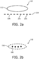
- Fig. 2a and Fig. 2b show two possible configurations of the X-ray device 110. Both configurations provide locations 106 from which X-rays emerge.
- the X-ray device 110 contains a single area 112 from which X-ray photons emerge. This area may be the common focal spot of a common X-ray tube.
- the emitted X-rays are collimated by a grating 114, which is configured to transmit X-rays only through its openings 106, which are therefore identical to the locations 106 of the X-ray device 110.
- the grating 114 is constructed or formed from highly opaque materials, such as, for example, Tungsten or Lead of appropriate thickness, such that the amount of transmitted radiation through the blockings 231 is reduced to a minimum.
- the X-ray beams 104 received by a particular pixel of detector 150 may pass only a particular number of locations 106, i.e., those locations 106 which are in the line-of-sight between a corresponding pixel of detector 150 and the X-ray emission area 112. Also it may be that X-ray beams 104 assigned to different pixels of detector 150 are assigned to completely different locations 106 of the X-ray device 110.
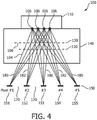
- the X-ray device 110 includes a single area 116 from which X-ray photons emerge in a spatially modulated intensity such that the locations 106 are represented by local intensity maxima of the X-ray area 116.
- the area 116 may be the focal spot of an X-ray tube for which the modulation of X-ray intensity is performed by a correspondingly varying density of electrons hitting the metal anode.
- the electrons may be generated from a spatially modulated electron source, and a common electron lens optics produces an "image" of the electron source, such that the focal spot displays the same spatial X-ray intensity pattern as the electron source area.
- the filter 120 forms a characteristic pattern of different X-ray filtration.
- this pattern may be in the form of alternating stripes that extend a horizontal (or vertical) length of the filter 120.
- the filter 120 is shown in a side view in Fig. 3a , where a first grating 210 and a second grating 220 are shown both differing from each other by different X-ray filtration properties.
- the filter 120 is shown in a top view in Fig. 3b , where the first grating 210 and the second grating 220 are shown extending a length of the filter 120.
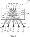
- This alternating pattern design of the filter 120 allows for alternating pixels of the plurality of pixels 151 to 155 to be illuminated with different X-ray spectra. For example, as shown in all of Fig. 1 , Fig. 4 , and Fig. 5 , the first pixel 151 receives a first spectra 180 and the second pixel 152 receives a second spectra 182. Additionally, the third pixel 153 and the fifth pixel 155 receive the first spectra 180, whereas the fourth pixel 154 receives the second spectra 182.
- the odd pixels i.e., pixels 151, 153, and 155
- the even pixels i.e., pixels 152 and 154
- each adjacent or neighboring pixel may receive different spectra (i.e., creation of an alternating configuration of spectra).
- spectrum separation may be achieved.
- the first spectra 180 may have a strong weight on high energy photons
- the second spectra 182 may have a strong weight on low energy photons, and vice versa.
- the filter 120 causes the generation of at least two spectra, such that no spatial overlap between the spectrum occurs, or the spatial spectrum overlap is reduced to a minimum for particular locations on the X-ray detector 150.
- a pattern used for a filter grating 120 needs to be aligned to the pattern of the X-ray emission locations 106 of the X-ray device 110, to the pattern of the optional collimator grating 130, and the geometry of the pixel array of the X-ray detector 150.
- subsets of pixels are assigned for the X-ray detector 150, which are aligned to the pattern of different X-ray spectra.
- the grating-line pattern of the filter grating 120 reported in Fig.
- 3a and 3b would be used together with a similar grating-line pattern of the X-ray emission locations 106 of the X-ray device, optionally a grating-line pattern of the collimator grating 130, and a rectangular pattern of detector pixels of the X-ray detector 150 where subsets of pixels form an interlacing grating-line pattern.
- Figs. 3a and 3b there are many more possibilities of pattern arrangement than those displayed in Figs. 3a and 3b .
- An alternative arrangement is, for example, shown in Fig. 3c where the filter grating 120 is formed by a two-dimensional pattern of rectangular tiles 230, 240. This tile pattern is used together with an X-ray device 110 having X-ray emission locations 106 arranged in rectangular array of almost point emitters, optionally with a collimator grating 130 having a rectangular array of openings 108, and an X-ray detector 150 with a rectangular pixel matrix with pixel subsets forming interlacing tile patterns.
- a detector pixel array configured to detect the alternating pattern of spectral filtration, i.e., each pixel detects a spectrum different from its direct neighboring pixel.
- the X-ray device 110, the filter grating 120, and the optional collimator grating 130 may be configured in a way that the first spectra 180 and second spectra 182 form an interlacing pattern with a larger periodicity such that a column, a row, or a tile of the pattern covers an detector area with size dimensions larger than that of a single detector pixel.
- the subsets of pixels may contain sequences of directly neighboring pixels.
- the size of a column, a row or a tile of the pattern represented by the subsets of pixels may correspond to the size of one pixel, but it is not limited to the size of one pixel and may therefore have a larger size.
- the X-ray device 110, the filter grating 120, and the optional collimator grating 130 and the detector 150 may be configured in a way that interlacing patterns with more than two spectra can be generated. For example, by choosing a filter grating providing means for three or more different X-ray filtrations and having appropriate grating pitches, it is possible to generate an alternating and interlacing sequence of three or more different spectra on the detector 150.
- a filter 120 fulfilling the configuration may be placed at different positions between X-ray device 110 and detector 150.
- Fig. 4 shows an alternative positioning of the filter grating 120 (it is noted that the grating pitch needs to be adapted according to the total system geometry).
- the filter grating 120 and the optional collimator grating 130 have to be mounted into the system.
- the filter grating 120 may be replaced by a combination of two or more filters 122 and 124 as shown, for example, in Fig. 5 .
- One skilled in the art may envision several more arrangements and patterning of an effective grating 120.
- the filter 120 may include or be formed of two or more different materials. Alternatively, the filter 120 may be formed from a single material providing different filtration by a modulation of the material thickness. One of the filter materials may be air or another weakly attenuating material. Effectively, this weakly attenuating material represents an effective zero attenuation of X-rays such that one of the subsets of pixels is assigned to an effectively unfiltered spectrum.
- one or more of the materials of the filter grating 120 may be formed of materials with relatively large K-edge energies, such as tantalum, tungsten, or lead which results in spectra filtration with a relatively enhanced transmission of photons with energies below the K-edge.
- the K-edge may be chosen high enough such that photons with energies below the K-edge may still pass the object placed in the object space 140.
- materials with a relatively low K-edge such as aluminum, copper or tin are also contemplated to create spectra which put more relative weight to "high" energies, since it is assumed that their K-edge energy is that low that photon energies below their K-edge will effectively not be able to transmit the object placed into the object space 140.
- one or more materials (or their thickness) of filter grating 120 may be made opaque for X-rays, such that at least one subset of pixels does not get illuminated by primary radiation. Consequently, radiation received by these pixels consists of scattered radiation only. By interpolation, the intensity received by the fully illuminated pixels may be corrected for by its scatter content.
Landscapes
- Health & Medical Sciences (AREA)
- Life Sciences & Earth Sciences (AREA)
- Engineering & Computer Science (AREA)
- Medical Informatics (AREA)
- Physics & Mathematics (AREA)
- General Health & Medical Sciences (AREA)
- High Energy & Nuclear Physics (AREA)
- Pathology (AREA)
- Heart & Thoracic Surgery (AREA)
- Optics & Photonics (AREA)
- Biophysics (AREA)
- Radiology & Medical Imaging (AREA)
- Biomedical Technology (AREA)
- Nuclear Medicine, Radiotherapy & Molecular Imaging (AREA)
- Molecular Biology (AREA)
- Surgery (AREA)
- Animal Behavior & Ethology (AREA)
- Public Health (AREA)
- Veterinary Medicine (AREA)
- Pulmonology (AREA)
- Theoretical Computer Science (AREA)
- General Engineering & Computer Science (AREA)
- Spectroscopy & Molecular Physics (AREA)
- Toxicology (AREA)
- Chemical & Material Sciences (AREA)
- Analytical Chemistry (AREA)
- Biochemistry (AREA)
- General Physics & Mathematics (AREA)
- Immunology (AREA)
- Apparatus For Radiation Diagnosis (AREA)
Applications Claiming Priority (2)
| Application Number | Priority Date | Filing Date | Title |
|---|---|---|---|
| US201462047127P | 2014-09-08 | 2014-09-08 | |
| PCT/IB2015/056617 WO2016038504A1 (en) | 2014-09-08 | 2015-09-01 | Systems and methods for grating modulation of spectra and intensity in computed tomography |
Publications (2)
| Publication Number | Publication Date |
|---|---|
| EP3193720A1 EP3193720A1 (en) | 2017-07-26 |
| EP3193720B1 true EP3193720B1 (en) | 2020-01-01 |
Family
ID=54186243
Family Applications (1)
| Application Number | Title | Priority Date | Filing Date |
|---|---|---|---|
| EP15767593.5A Active EP3193720B1 (en) | 2014-09-08 | 2015-09-01 | Systems and methods for grating modulation of spectra and intensity in computed tomography |
Country Status (5)
| Country | Link |
|---|---|
| US (1) | US10470722B2 (enExample) |
| EP (1) | EP3193720B1 (enExample) |
| JP (1) | JP6946180B2 (enExample) |
| CN (1) | CN106687042B (enExample) |
| WO (1) | WO2016038504A1 (enExample) |
Cited By (1)
| Publication number | Priority date | Publication date | Assignee | Title |
|---|---|---|---|---|
| EP4377680A4 (en) * | 2021-07-28 | 2025-09-24 | Univ Bar Ilan | METHOD AND SYSTEM FOR HIGH PHOTONIC ENERGY IMAGING |
Families Citing this family (16)
| Publication number | Priority date | Publication date | Assignee | Title |
|---|---|---|---|---|
| DE102015226489B4 (de) * | 2015-12-22 | 2024-05-16 | Siemens Healthineers Ag | Röntgensystem und Verfahren zur Bildrekonstruktion |
| US11051772B2 (en) * | 2016-04-08 | 2021-07-06 | Rensselaer Polytechnic Institute | Filtration methods for dual-energy X-ray CT |
| WO2017176976A1 (en) * | 2016-04-08 | 2017-10-12 | Rensselaer Polytechnic Institute | Rapid filtration methods for dual-energy x-ray ct |
| US11016218B2 (en) * | 2016-07-28 | 2021-05-25 | Smiths Heimann Sas | Scatter imaging |
| EP3521862A1 (en) * | 2018-02-02 | 2019-08-07 | Koninklijke Philips N.V. | Multi-spectral x-ray detector |
| KR101980533B1 (ko) * | 2018-07-24 | 2019-05-21 | 주식회사 레메디 | 이중 에너지 x선 촬영 장치 |
| CN111096761B (zh) * | 2018-10-29 | 2024-03-08 | 上海西门子医疗器械有限公司 | 修正楔形滤波器散射的方法、装置和相关设备 |
| CN111134710B (zh) * | 2020-01-17 | 2021-05-07 | 清华大学 | 一种多能量ct成像系统 |
| CN112212855B (zh) * | 2020-09-08 | 2022-08-26 | 山东航天电子技术研究所 | 一种应用于x射线脉冲星导航终端的轻小型探测器 |
| CN112716517A (zh) * | 2020-12-31 | 2021-04-30 | 北京朗视仪器有限公司 | 一种通过dr拍摄测量骨密度的方法及dr拍摄设备 |
| CN114767140A (zh) * | 2022-04-07 | 2022-07-22 | 北京朗视仪器股份有限公司 | X射线滤波器、能谱成像系统及特异性组织鉴别方法 |
| CN114983465A (zh) * | 2022-05-09 | 2022-09-02 | 有方(合肥)医疗科技有限公司 | 成像设备和成像方法 |
| CN115105107A (zh) * | 2022-06-20 | 2022-09-27 | 北京朗视仪器股份有限公司 | 一种能谱成像方法及能谱成像系统 |
| US12493003B2 (en) | 2023-07-13 | 2025-12-09 | General Electric Company | Detector with focally aligned pixels |
| DE102023211966A1 (de) | 2023-11-29 | 2025-06-05 | Siemens Healthineers Ag | Computerimplementiertes Verfahren zum Betrieb einer Röntgeneinrichtung und Röntgeneinrichtung |
| CN118975808B (zh) * | 2024-07-16 | 2025-09-09 | 华中科技大学 | 多能谱x射线面阵成像系统 |
Citations (1)
| Publication number | Priority date | Publication date | Assignee | Title |
|---|---|---|---|---|
| US20030089857A1 (en) * | 2001-10-23 | 2003-05-15 | Siemens Aktiengesellschaft | X-ray detector with an applied stray radiation grid, and method for applying a stray radiation grid to an X-ray detector |
Family Cites Families (14)
| Publication number | Priority date | Publication date | Assignee | Title |
|---|---|---|---|---|
| US3950613A (en) | 1973-12-26 | 1976-04-13 | Albert Macovski | X-ray encoding and decoding system |
| JPS54154294A (en) * | 1978-05-26 | 1979-12-05 | Toshiba Corp | Computer tomography device |
| US7099428B2 (en) * | 2002-06-25 | 2006-08-29 | The Regents Of The University Of Michigan | High spatial resolution X-ray computed tomography (CT) system |
| US7050529B2 (en) * | 2002-07-23 | 2006-05-23 | Ge Medical Systems Global Technolgy Company, Llc | Methods and apparatus for performing a computed tomography scan |
| US6950495B2 (en) * | 2003-12-01 | 2005-09-27 | The Boeing Company | Backscatter imaging using Hadamard transform masking |
| AU2005295554A1 (en) * | 2004-10-14 | 2006-04-27 | Eklin Medical Systems, Inc. | Polychromic digital radiography detector with patterned mask for single-exposure energy-sensitive X-ray imaging |
| US7496181B2 (en) | 2005-11-28 | 2009-02-24 | The Board Of Trustees Of The Leland Stanford Junior University | X-ray collimator for imaging with multiple sources and detectors |
| WO2007110795A2 (en) * | 2006-03-29 | 2007-10-04 | Philips Intellectual Property & Standards Gmbh | Effective dual-energy x-ray attenuation measurement |
| JP5294653B2 (ja) * | 2008-02-28 | 2013-09-18 | キヤノン株式会社 | マルチx線発生装置及びx線撮影装置 |
| JP5247363B2 (ja) * | 2008-11-11 | 2013-07-24 | キヤノン株式会社 | X線撮影装置 |
| WO2011027390A1 (ja) * | 2009-09-02 | 2011-03-10 | 株式会社島津製作所 | 放射線撮影装置および画像の取得方法 |
| KR101228911B1 (ko) * | 2010-08-06 | 2013-02-15 | 라드텍주식회사 | 이중 에너지 x-선 흡광분석을 이용한 x-선 영상장치 |
| US9599577B2 (en) | 2010-09-06 | 2017-03-21 | Koninklijke Philips N.V. | X-ray imaging with pixelated detector |
| WO2014100063A1 (en) * | 2012-12-21 | 2014-06-26 | Carestream Health, Inc. | Medical radiographic grating based differential phase contrast imaging |
-
2015
- 2015-09-01 US US15/506,959 patent/US10470722B2/en active Active
- 2015-09-01 JP JP2017512922A patent/JP6946180B2/ja active Active
- 2015-09-01 WO PCT/IB2015/056617 patent/WO2016038504A1/en not_active Ceased
- 2015-09-01 EP EP15767593.5A patent/EP3193720B1/en active Active
- 2015-09-01 CN CN201580048218.7A patent/CN106687042B/zh active Active
Patent Citations (1)
| Publication number | Priority date | Publication date | Assignee | Title |
|---|---|---|---|---|
| US20030089857A1 (en) * | 2001-10-23 | 2003-05-15 | Siemens Aktiengesellschaft | X-ray detector with an applied stray radiation grid, and method for applying a stray radiation grid to an X-ray detector |
Cited By (1)
| Publication number | Priority date | Publication date | Assignee | Title |
|---|---|---|---|---|
| EP4377680A4 (en) * | 2021-07-28 | 2025-09-24 | Univ Bar Ilan | METHOD AND SYSTEM FOR HIGH PHOTONIC ENERGY IMAGING |
Also Published As
| Publication number | Publication date |
|---|---|
| JP6946180B2 (ja) | 2021-10-06 |
| CN106687042B (zh) | 2021-08-03 |
| US10470722B2 (en) | 2019-11-12 |
| CN106687042A (zh) | 2017-05-17 |
| WO2016038504A1 (en) | 2016-03-17 |
| EP3193720A1 (en) | 2017-07-26 |
| JP2017526457A (ja) | 2017-09-14 |
| US20170273642A1 (en) | 2017-09-28 |
Similar Documents
| Publication | Publication Date | Title |
|---|---|---|
| EP3193720B1 (en) | Systems and methods for grating modulation of spectra and intensity in computed tomography | |
| US10393890B2 (en) | X-ray imaging device | |
| US9599577B2 (en) | X-ray imaging with pixelated detector | |
| US9204852B2 (en) | Systems and methods for increased energy separation in multi-energy X-ray imaging | |
| EP2008285B1 (en) | Production of x-ray images containing a reduced proportion of scattered radiation | |
| CN102764137B (zh) | 一种静态ct扫描仪及其散射x光子校正方法 | |
| US10571579B2 (en) | Dual-mode radiation detector | |
| US10045749B2 (en) | X-ray system, in particular a tomosynthesis system and a method for acquiring an image of an object | |
| JP2017526457A5 (enExample) | ||
| US6332015B1 (en) | Radiographic diagnosis apparatus, radiographic diagnosis method, plate member, and position detecting method | |
| US9360439B2 (en) | Imaging system | |
| JP2015024097A5 (enExample) | ||
| JP6538721B2 (ja) | レーザー・コンプトンx線源を用いた二色放射線撮影の方法 | |
| US20140185758A1 (en) | Apparatus and method for increasing energy difference in multi-energy x-ray (mex) images | |
| JP2023516986A (ja) | 放射線検出システム | |
| Speidel et al. | Detector, collimator and real-time reconstructor for a new scanning-beam digital x-ray (SBDX) prototype | |
| Engel et al. | Spectral analysis of scattered radiation in CT | |
| US20190293573A1 (en) | Grating-based phase contrast imaging | |
| KR101685005B1 (ko) | 저선량 엑스선 콘빔 ct 영상 장치 및 이를 이용한 영상 생성 방법 | |
| CN120898151A (zh) | 具有模块化双层探测器的x射线系统 | |
| KR20200012119A (ko) | 샌드위치 구조의 광계수 검출기를 이용한 골밀도 검사 센서 | |
| HK1234632B (en) | Methods for 2-color radiography with laser-compton x-ray sources |
Legal Events
| Date | Code | Title | Description |
|---|---|---|---|
| STAA | Information on the status of an ep patent application or granted ep patent |
Free format text: STATUS: THE INTERNATIONAL PUBLICATION HAS BEEN MADE |
|
| PUAI | Public reference made under article 153(3) epc to a published international application that has entered the european phase |
Free format text: ORIGINAL CODE: 0009012 |
|
| STAA | Information on the status of an ep patent application or granted ep patent |
Free format text: STATUS: REQUEST FOR EXAMINATION WAS MADE |
|
| 17P | Request for examination filed |
Effective date: 20170410 |
|
| AK | Designated contracting states |
Kind code of ref document: A1 Designated state(s): AL AT BE BG CH CY CZ DE DK EE ES FI FR GB GR HR HU IE IS IT LI LT LU LV MC MK MT NL NO PL PT RO RS SE SI SK SM TR |
|
| AX | Request for extension of the european patent |
Extension state: BA ME |
|
| DAV | Request for validation of the european patent (deleted) | ||
| DAX | Request for extension of the european patent (deleted) | ||
| STAA | Information on the status of an ep patent application or granted ep patent |
Free format text: STATUS: EXAMINATION IS IN PROGRESS |
|
| 17Q | First examination report despatched |
Effective date: 20180104 |
|
| GRAP | Despatch of communication of intention to grant a patent |
Free format text: ORIGINAL CODE: EPIDOSNIGR1 |
|
| STAA | Information on the status of an ep patent application or granted ep patent |
Free format text: STATUS: GRANT OF PATENT IS INTENDED |
|
| INTG | Intention to grant announced |
Effective date: 20190731 |
|
| GRAS | Grant fee paid |
Free format text: ORIGINAL CODE: EPIDOSNIGR3 |
|
| GRAA | (expected) grant |
Free format text: ORIGINAL CODE: 0009210 |
|
| STAA | Information on the status of an ep patent application or granted ep patent |
Free format text: STATUS: THE PATENT HAS BEEN GRANTED |
|
| AK | Designated contracting states |
Kind code of ref document: B1 Designated state(s): AL AT BE BG CH CY CZ DE DK EE ES FI FR GB GR HR HU IE IS IT LI LT LU LV MC MK MT NL NO PL PT RO RS SE SI SK SM TR |
|
| REG | Reference to a national code |
Ref country code: GB Ref legal event code: FG4D |
|
| REG | Reference to a national code |
Ref country code: CH Ref legal event code: EP Ref country code: AT Ref legal event code: REF Ref document number: 1218771 Country of ref document: AT Kind code of ref document: T Effective date: 20200115 |
|
| REG | Reference to a national code |
Ref country code: DE Ref legal event code: R096 Ref document number: 602015044724 Country of ref document: DE |
|
| REG | Reference to a national code |
Ref country code: IE Ref legal event code: FG4D |
|
| RAP2 | Party data changed (patent owner data changed or rights of a patent transferred) |
Owner name: KONINKLIJKE PHILIPS N.V. |
|
| REG | Reference to a national code |
Ref country code: DE Ref legal event code: R084 Ref document number: 602015044724 Country of ref document: DE |
|
| REG | Reference to a national code |
Ref country code: NL Ref legal event code: MP Effective date: 20200101 |
|
| REG | Reference to a national code |
Ref country code: LT Ref legal event code: MG4D |
|
| PG25 | Lapsed in a contracting state [announced via postgrant information from national office to epo] |
Ref country code: PT Free format text: LAPSE BECAUSE OF FAILURE TO SUBMIT A TRANSLATION OF THE DESCRIPTION OR TO PAY THE FEE WITHIN THE PRESCRIBED TIME-LIMIT Effective date: 20200527 Ref country code: CZ Free format text: LAPSE BECAUSE OF FAILURE TO SUBMIT A TRANSLATION OF THE DESCRIPTION OR TO PAY THE FEE WITHIN THE PRESCRIBED TIME-LIMIT Effective date: 20200101 Ref country code: LT Free format text: LAPSE BECAUSE OF FAILURE TO SUBMIT A TRANSLATION OF THE DESCRIPTION OR TO PAY THE FEE WITHIN THE PRESCRIBED TIME-LIMIT Effective date: 20200101 Ref country code: RS Free format text: LAPSE BECAUSE OF FAILURE TO SUBMIT A TRANSLATION OF THE DESCRIPTION OR TO PAY THE FEE WITHIN THE PRESCRIBED TIME-LIMIT Effective date: 20200101 Ref country code: NO Free format text: LAPSE BECAUSE OF FAILURE TO SUBMIT A TRANSLATION OF THE DESCRIPTION OR TO PAY THE FEE WITHIN THE PRESCRIBED TIME-LIMIT Effective date: 20200401 Ref country code: FI Free format text: LAPSE BECAUSE OF FAILURE TO SUBMIT A TRANSLATION OF THE DESCRIPTION OR TO PAY THE FEE WITHIN THE PRESCRIBED TIME-LIMIT Effective date: 20200101 Ref country code: NL Free format text: LAPSE BECAUSE OF FAILURE TO SUBMIT A TRANSLATION OF THE DESCRIPTION OR TO PAY THE FEE WITHIN THE PRESCRIBED TIME-LIMIT Effective date: 20200101 |
|
| PG25 | Lapsed in a contracting state [announced via postgrant information from national office to epo] |
Ref country code: IS Free format text: LAPSE BECAUSE OF FAILURE TO SUBMIT A TRANSLATION OF THE DESCRIPTION OR TO PAY THE FEE WITHIN THE PRESCRIBED TIME-LIMIT Effective date: 20200501 Ref country code: GR Free format text: LAPSE BECAUSE OF FAILURE TO SUBMIT A TRANSLATION OF THE DESCRIPTION OR TO PAY THE FEE WITHIN THE PRESCRIBED TIME-LIMIT Effective date: 20200402 Ref country code: LV Free format text: LAPSE BECAUSE OF FAILURE TO SUBMIT A TRANSLATION OF THE DESCRIPTION OR TO PAY THE FEE WITHIN THE PRESCRIBED TIME-LIMIT Effective date: 20200101 Ref country code: HR Free format text: LAPSE BECAUSE OF FAILURE TO SUBMIT A TRANSLATION OF THE DESCRIPTION OR TO PAY THE FEE WITHIN THE PRESCRIBED TIME-LIMIT Effective date: 20200101 Ref country code: SE Free format text: LAPSE BECAUSE OF FAILURE TO SUBMIT A TRANSLATION OF THE DESCRIPTION OR TO PAY THE FEE WITHIN THE PRESCRIBED TIME-LIMIT Effective date: 20200101 Ref country code: BG Free format text: LAPSE BECAUSE OF FAILURE TO SUBMIT A TRANSLATION OF THE DESCRIPTION OR TO PAY THE FEE WITHIN THE PRESCRIBED TIME-LIMIT Effective date: 20200401 |
|
| REG | Reference to a national code |
Ref country code: DE Ref legal event code: R097 Ref document number: 602015044724 Country of ref document: DE |
|
| PG25 | Lapsed in a contracting state [announced via postgrant information from national office to epo] |
Ref country code: DK Free format text: LAPSE BECAUSE OF FAILURE TO SUBMIT A TRANSLATION OF THE DESCRIPTION OR TO PAY THE FEE WITHIN THE PRESCRIBED TIME-LIMIT Effective date: 20200101 Ref country code: EE Free format text: LAPSE BECAUSE OF FAILURE TO SUBMIT A TRANSLATION OF THE DESCRIPTION OR TO PAY THE FEE WITHIN THE PRESCRIBED TIME-LIMIT Effective date: 20200101 Ref country code: SM Free format text: LAPSE BECAUSE OF FAILURE TO SUBMIT A TRANSLATION OF THE DESCRIPTION OR TO PAY THE FEE WITHIN THE PRESCRIBED TIME-LIMIT Effective date: 20200101 Ref country code: ES Free format text: LAPSE BECAUSE OF FAILURE TO SUBMIT A TRANSLATION OF THE DESCRIPTION OR TO PAY THE FEE WITHIN THE PRESCRIBED TIME-LIMIT Effective date: 20200101 Ref country code: RO Free format text: LAPSE BECAUSE OF FAILURE TO SUBMIT A TRANSLATION OF THE DESCRIPTION OR TO PAY THE FEE WITHIN THE PRESCRIBED TIME-LIMIT Effective date: 20200101 Ref country code: SK Free format text: LAPSE BECAUSE OF FAILURE TO SUBMIT A TRANSLATION OF THE DESCRIPTION OR TO PAY THE FEE WITHIN THE PRESCRIBED TIME-LIMIT Effective date: 20200101 |
|
| PLBE | No opposition filed within time limit |
Free format text: ORIGINAL CODE: 0009261 |
|
| STAA | Information on the status of an ep patent application or granted ep patent |
Free format text: STATUS: NO OPPOSITION FILED WITHIN TIME LIMIT |
|
| REG | Reference to a national code |
Ref country code: AT Ref legal event code: MK05 Ref document number: 1218771 Country of ref document: AT Kind code of ref document: T Effective date: 20200101 |
|
| 26N | No opposition filed |
Effective date: 20201002 |
|
| PG25 | Lapsed in a contracting state [announced via postgrant information from national office to epo] |
Ref country code: IT Free format text: LAPSE BECAUSE OF FAILURE TO SUBMIT A TRANSLATION OF THE DESCRIPTION OR TO PAY THE FEE WITHIN THE PRESCRIBED TIME-LIMIT Effective date: 20200101 Ref country code: AT Free format text: LAPSE BECAUSE OF FAILURE TO SUBMIT A TRANSLATION OF THE DESCRIPTION OR TO PAY THE FEE WITHIN THE PRESCRIBED TIME-LIMIT Effective date: 20200101 |
|
| PG25 | Lapsed in a contracting state [announced via postgrant information from national office to epo] |
Ref country code: SI Free format text: LAPSE BECAUSE OF FAILURE TO SUBMIT A TRANSLATION OF THE DESCRIPTION OR TO PAY THE FEE WITHIN THE PRESCRIBED TIME-LIMIT Effective date: 20200101 Ref country code: PL Free format text: LAPSE BECAUSE OF FAILURE TO SUBMIT A TRANSLATION OF THE DESCRIPTION OR TO PAY THE FEE WITHIN THE PRESCRIBED TIME-LIMIT Effective date: 20200101 |
|
| PG25 | Lapsed in a contracting state [announced via postgrant information from national office to epo] |
Ref country code: MC Free format text: LAPSE BECAUSE OF FAILURE TO SUBMIT A TRANSLATION OF THE DESCRIPTION OR TO PAY THE FEE WITHIN THE PRESCRIBED TIME-LIMIT Effective date: 20200101 |
|
| REG | Reference to a national code |
Ref country code: CH Ref legal event code: PL |
|
| GBPC | Gb: european patent ceased through non-payment of renewal fee |
Effective date: 20200901 |
|
| REG | Reference to a national code |
Ref country code: BE Ref legal event code: MM Effective date: 20200930 |
|
| PG25 | Lapsed in a contracting state [announced via postgrant information from national office to epo] |
Ref country code: LU Free format text: LAPSE BECAUSE OF NON-PAYMENT OF DUE FEES Effective date: 20200901 |
|
| PG25 | Lapsed in a contracting state [announced via postgrant information from national office to epo] |
Ref country code: GB Free format text: LAPSE BECAUSE OF NON-PAYMENT OF DUE FEES Effective date: 20200901 Ref country code: LI Free format text: LAPSE BECAUSE OF NON-PAYMENT OF DUE FEES Effective date: 20200930 Ref country code: IE Free format text: LAPSE BECAUSE OF NON-PAYMENT OF DUE FEES Effective date: 20200901 Ref country code: CH Free format text: LAPSE BECAUSE OF NON-PAYMENT OF DUE FEES Effective date: 20200930 Ref country code: BE Free format text: LAPSE BECAUSE OF NON-PAYMENT OF DUE FEES Effective date: 20200930 |
|
| PG25 | Lapsed in a contracting state [announced via postgrant information from national office to epo] |
Ref country code: TR Free format text: LAPSE BECAUSE OF FAILURE TO SUBMIT A TRANSLATION OF THE DESCRIPTION OR TO PAY THE FEE WITHIN THE PRESCRIBED TIME-LIMIT Effective date: 20200101 Ref country code: MT Free format text: LAPSE BECAUSE OF FAILURE TO SUBMIT A TRANSLATION OF THE DESCRIPTION OR TO PAY THE FEE WITHIN THE PRESCRIBED TIME-LIMIT Effective date: 20200101 Ref country code: CY Free format text: LAPSE BECAUSE OF FAILURE TO SUBMIT A TRANSLATION OF THE DESCRIPTION OR TO PAY THE FEE WITHIN THE PRESCRIBED TIME-LIMIT Effective date: 20200101 |
|
| PG25 | Lapsed in a contracting state [announced via postgrant information from national office to epo] |
Ref country code: MK Free format text: LAPSE BECAUSE OF FAILURE TO SUBMIT A TRANSLATION OF THE DESCRIPTION OR TO PAY THE FEE WITHIN THE PRESCRIBED TIME-LIMIT Effective date: 20200101 Ref country code: AL Free format text: LAPSE BECAUSE OF FAILURE TO SUBMIT A TRANSLATION OF THE DESCRIPTION OR TO PAY THE FEE WITHIN THE PRESCRIBED TIME-LIMIT Effective date: 20200101 |
|
| PGFP | Annual fee paid to national office [announced via postgrant information from national office to epo] |
Ref country code: DE Payment date: 20250926 Year of fee payment: 11 |
|
| PGFP | Annual fee paid to national office [announced via postgrant information from national office to epo] |
Ref country code: FR Payment date: 20250925 Year of fee payment: 11 |