EP3193085B1 - Gargerät - Google Patents
Gargerät Download PDFInfo
- Publication number
- EP3193085B1 EP3193085B1 EP16203993.7A EP16203993A EP3193085B1 EP 3193085 B1 EP3193085 B1 EP 3193085B1 EP 16203993 A EP16203993 A EP 16203993A EP 3193085 B1 EP3193085 B1 EP 3193085B1
- Authority
- EP
- European Patent Office
- Prior art keywords
- lamp body
- cooking
- holding device
- cooking appliance
- light guide
- Prior art date
- Legal status (The legal status is an assumption and is not a legal conclusion. Google has not performed a legal analysis and makes no representation as to the accuracy of the status listed.)
- Revoked
Links
Images


Classifications
-
- F—MECHANICAL ENGINEERING; LIGHTING; HEATING; WEAPONS; BLASTING
- F24—HEATING; RANGES; VENTILATING
- F24C—DOMESTIC STOVES OR RANGES ; DETAILS OF DOMESTIC STOVES OR RANGES, OF GENERAL APPLICATION
- F24C15/00—Details
- F24C15/008—Illumination for oven cavities
Definitions
- the present invention relates to a cooking appliance with at least one cooking space. At least one lighting device is assigned to the cooking space.
- the lighting device comprises a lamp body and a light guide emanating from the lamp body.
- a cooking chamber lighting is provided in the cooking chamber of many cooking appliances. Often times the lighting in the cooking space is arranged behind a window in the wall of the cooking space. A lamp in the oven lighting shines light through the window into the oven.
- the disadvantage of such lighting is that not all rack levels may be adequately illuminated.
- a cooking device which has a housing with a cooking space with a closable cooking space opening, at least one lighting device being assigned to the cooking space.
- This comprises a circuit carrier with a light source and a light guide emanating from the light source.
- the light guide extends through a rod-shaped leadthrough in a holder and has a slip protection.
- the US2012 / 125911 A1 discloses a cooking appliance with a lighting device.
- light sources are assigned to a bow-shaped light guide at both ends.
- the light guide is held in a housing.
- the household appliance can also be a stove, that is, a cooking appliance.
- a circuit board On a circuit board is an LED and a holder arranged above it, the holder accommodates a light guide element which guides the light into the interior of the device.
- the US 2009/316385 A1 describes in a first embodiment ( Figures 1 to 5 ) a cooking appliance with a lighting device which comprises a lamp body and a.
- a light guide is provided with a reflective strip and is held in a cap-shaped holder.
- Another embodiment shows a U-shaped light guide that extends into the cooking space.
- the cooking appliance according to the invention has at least one appliance body which provides a cooking space with a closable cooking space opening.
- At least one lighting device is assigned to the cooking space.
- the lighting device comprises a lamp body and a light guide emanating from the lamp body.
- the lamp body is attached to the device body in an operating position by means of at least one mounting device.
- the light guide extends into the cooking space.
- the light guide has at least one exit section for the light at least on its long side.
- the assembly device comprises at least one positioning device.
- the positioning device is suitable and designed to at least partially fix the lamp body and the light guide connected to it in the operating position before they are attached. This fixation by the positioning device is provided to hold the exit section at a certain emission angle.
- the positioning device comprises at least one positioning unit.
- the positioning unit is suitable and designed to block the rotatability of the lamp body and the light guide about their longitudinal axis by means of at least two fixation elements lying against one another in a form-fitting manner.
- the cooking appliance according to the invention offers many advantages.
- the positioning device by means of which the outlet section is already locked in a defined operating position before the final fastening during assembly, offers a considerable advantage.
- the beam angle can be very simple and very reliable and without time-consuming adjustment work in particular can be set at an exact angle.
- the light guide only needs to be inserted into the cooking space and the lamp body is then fixed by the positioning device.
- the lamp body with the light guide connected to it can now be attached quickly and easily without further adjustment.
- a check and adjustment of the beam angle which may require time-consuming switching on of the lighting, is no longer necessary. As a result, costs and time can be saved when assembling the cooking device according to the invention.
- the light guide and the lamp body are non-rotatably connected to one another. As a result, the light guide and the lamp body can only be rotated together about their longitudinal axis.
- the lamp body comprises in particular at least one lighting means.
- the lamp body can also comprise at least one cooling device and / or a receiving device for the light guide.
- At least one light-emitting diode and in particular a plurality of light-emitting diodes are preferably provided as the lighting means.
- the lamp body Before it is fastened, the lamp body can in particular be aligned and is preferably received so as to be rotatable about a longitudinal axis of the light guide and / or about its own longitudinal axis.
- the positioning device is preferably suitable and designed to fix the lamp body and the light guide connected to it in the intended operating position, at least with regard to the angle of rotation about their common longitudinal axis, before they are fastened.
- the light guide and lamp body can be rotated about their longitudinal axis when the light guide is inserted into the cooking space. This rotatability is fixed when it is inserted into the positioning device in such a way that the exit section of the light guide is aligned in the desired emission angle. It is then fastened using the assembly device.
- the light guide comprises at least one rod section which is round.
- the light guide is made available by a round rod section.
- the light guide is particularly preferably provided by a round glass rod.
- An angular and / or non-circular rod section is also possible.
- a triangular or square or polygonal rod section can be provided.
- An oval rod section is also possible. In the case of angular or oval rod sections, this is preferably passed through a correspondingly large recess in the mounting device, which allows the light guide to rotate. As a result, the light guide can be rotated in the assembly device and fixed in the desired position by the positioning device.
- the round light guide is preferably guided through at least one round recess in the mounting device, so that the light guide and the lamp body are fixed by the positioning device before they are fixed are rotatable about their longitudinal axis.
- a round light guide is particularly easy to install because it can be inserted into the cooking space at any angle.
- the mounting device comprises at least one holding device for receiving the lighting device.
- the mounting device is arranged with at least one section on the device body and with at least one other section on the lamp body. This is particularly advantageous since the holding device only needs to be adapted in order to be able to mount the lighting device on different device bodies.
- the holding device is preferably attached outside the cooking chamber and, for example, on a muffle.
- At least one fixing element is arranged on the holding device. And at least one fixing element serving as a counterpart is arranged on the lamp body. This considerably simplifies assembly, since it is fixed in the operating position directly when the lamp body is inserted into the holding device. It is also possible that at least one fixing element is arranged on the device body and at least one fixing element serving as a counterpart is arranged on the lamp body. This is particularly advantageous when the lamp body is mounted directly on the device body.
- At least one fixing element is designed as an elevation.
- at least one fixing element serving as a counterpart is designed as a recess.
- Such fixing elements can be implemented constructively in a simple and cost-effective manner and offer reliable fixing.
- a fixing element is designed as a pin and the fixing element serving as a counterpart is designed as a bore or recess.
- a positive fit is particularly preferably provided for the fixing elements.
- a round pin engages in a round hole.
- the holding device prefferably has at least one elongate guide section through which the light guide runs.
- a guide section considerably facilitates the introduction of the light guide into the cooking space.
- a correspondingly large amount of assembly time can be saved, particularly with sensitive glass fiber optics.
- the elongate guide section comprises at least one spacer or is designed as such.
- the spacer is particularly suitable and designed to provide a distance between the lamp body and the device body and / or the muffle. Such a complaint about the lamp body prevents, for example, undesired heating during operation.
- the holding device preferably comprises at least one latch for latching the lamp body.
- a latching offers a fast and at the same time reliable Attachment of the lamp body to the holding device.
- the latching and the positioning unit are particularly preferably suitable and designed to latch the lamp body only in a fixed position. Such an alignment of the positioning unit and latching with respect to one another considerably increases the reliability of assembly, since when latching has taken place there is also a correct fixing and thus a correct alignment of the emission angle.
- the latching is suitable and designed to transmit a latching of the lamp body acoustically and / or haptically and / or optically to the fitter.
- the holding device comprises at least one floating bearing.
- the floating bearing is particularly suitable and designed to accommodate the lamp body while maintaining a defined play in at least one direction of movement.
- a floating bearing can, for example, compensate for an expansion that occurs when the lighting device and / or the device body are heated.
- such a loose bearing can also allow the light guide to retreat in the event of a shock, for example when wiping out the cooking space.
- the light guide is particularly well protected from damage by such a loose bearing.
- the floating bearing is particularly preferably suitable and designed to accommodate the lamp body with play in the longitudinal direction of the light guide. There can also be play with regard to the fixed rotatability of the lamp body and light guide.
- the latching is preferably suitable and designed to serve as a floating bearing.
- the latching is particularly suitable and designed to latch the lamp body with a defined play.
- at least one further storage device is provided for the light guide.
- at least one fixed bearing and / or at least one spring bearing is provided for fastening the light guide in the cooking space.
- the positioning device comprises at least two positioning units.
- Each positioning unit preferably comprises two fixing elements, for example in each case an elevation and a recess serving as a counterpart.
- the stability of the fixation can be improved by using two or more positioning units.
- the positioning units are preferably aligned with one another in an arrangement which allows only one fixable operating position.
- the positioning units do not lie on an imaginary straight line which runs through the axis of rotation of the lamp body around the longitudinal axis of the light guide.
- the positioning units lie on a chord of an imaginary circle which runs around the lamp body.
- the positioning units lie on an imaginary circular arc around the lamp body and have an angle of unequal 180 ° to one another. For example, an angle of 200 ° is provided. Other angles are also possible. It is also possible for the positioning units to have a different distance from the axis of rotation of the lamp body around the longitudinal axis of the light guide.
- At least two lighting devices are assigned to the cooking space.
- At least one positioning device and at least one holding device are assigned to each of the lighting devices.
- the lamp bodies of the lighting devices are designed to be identical, at least with regard to their fixing elements.
- the lamp bodies and the light guides connected to them are arranged rotated about their longitudinal axis, in particular on opposite sides of the cooking space. Such a configuration also correctly fixes and attaches lighting devices with individual beam angles for each side of the cooking space.
- only one type of lamp body has to be kept available during assembly.
- the lighting devices are arranged, for example, to the right and left of the cooking chamber opening. An arrangement on the upper and lower walls of the cooking space is also possible.
- the cooking space can also be assigned three or four or more lighting devices. At least one holding device and at least one positioning device are then preferably provided for each lighting device.
- the lamp bodies are preferably arranged rotated by 180 ° with respect to one another. The rotation takes place in particular about the longitudinal axis of the light guide.
- the lighting devices differ at least in that the exit section of the light guide is arranged in a mirrored manner.
- This preferably also results in a mirrored arrangement of the radiation angle.
- Such a configuration is particularly advantageous when the lighting devices are arranged on the edges of opposite side walls. This is the case, for example, when the lighting devices are arranged on the left and right side walls of the cooking space in the vicinity of the cooking space opening.
- the outlet section is preferably arranged in a mirrored manner along an axis or a plane.
- the holding devices of the at least two lighting devices are preferably designed to be identical, at least with regard to their fixing elements.
- the holding devices are preferably arranged on opposite sides of the cooking space rotated about their longitudinal axis. This has the advantage that when installing two lighting devices in a cooking space, each with individual radiation angles, only one type of holding device has to be kept for each side of the cooking space.
- the holding devices are particularly preferably arranged on opposite sides of the cooking space rotated by 180 ° about their longitudinal axis. Other angles of rotation are also possible.
- an inventive cooking device 1 is shown purely schematically in a perspective view.
- the cooking appliance 1 is integrated into a kitchen unit 100 and designed as an oven 101.
- a hob is embedded in the worktop of the kitchen unit 100.
- the cooking appliance 1 has an operating device for making settings 103 on.
- the cooking device 1 is designed here as a built-in device.
- the cooking appliance 1 can, however, also be designed as a stove or floor-standing appliance.
- the cooking space 11 of the cooking appliance 1 has a cooking space opening 21 which is closed here by a cooking space door 104.
- the cooking space 11 can be heated by various heat sources. Among other things, heating with a circulating air heating source, with upper and lower heating, in hot air mode and / or with a gas heating source is possible. It is also possible that the cooking appliance 1 is designed as a combination appliance with a microwave function and / or a steam cooking function. To illuminate the cooking space 11, a lighting device 3, not shown here, is provided.
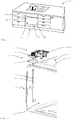
- the Figure 2 shows a cooking appliance 1 in a perspective representation, in which only certain components have been drawn in for better clarity.
- the cooking space 11 is provided here by a device body 2 which has a muffle 12.
- the muffle 12 surrounds the cooking space 11 with an upper and a lower wall, two side walls and a rear wall.
- the cooking chamber opening 21 is arranged on the front of the muffle 12.
- the device body 2 can have further components, not shown here, such as a housing, an insulation of the muffle 12 and / or a cooking chamber door 104 as well as further components.
- a receiving device for food carriers is preferably provided in the cooking space 11.
- the lighting device 3 here comprises a lamp body 4 which is arranged outside the muffle 12 and which has a cooling body 14 and a lighting means (not shown).
- a lamp body 4 which is arranged outside the muffle 12 and which has a cooling body 14 and a lighting means (not shown).
- As light sources are z. B. several light emitting diodes are provided. However, only a single light-emitting diode can be provided as a light source.
- the lamp body 4 is operatively connected here to a control device 102 for energy supply and control.
- a light guide 13 designed as a glass rod 43 is attached to the lamp body 4.
- the glass rod 43 is round here and fastened to the lamp body 4 in a rotationally fixed manner.
- the light guide 13 extends from the lamp body 4 through a recess in the muffle 12 into the cooking space 11.
- the light guide 13 is arranged here in a front section of the cooking space 11. The arrangement of the light guide 13 adjacent to the cooking chamber opening 21 results in particularly good illumination of the cooking chamber 11.
- the light guide is fastened in the cooking chamber 11 by means of two storage devices.
- the bearing device on the upper section of the light guide 13 is designed as a spring bearing. This enables flexible retraction of the light guide, for example when it is touched when wiping the cooking space 11.
- a fixed bearing is provided here on a lower section of the light guide 13, which keeps the light guide stable in its position. It is possible that the fixed bearing enables the light guide 13 to move along its longitudinal axis. In this way, for example, thermal expansion can be compensated.
- a mounting device 5 is provided here for fastening the lighting device 3.
- the assembly device 5 includes various fastening options for the components of the lighting device 3, such as a screw connection for the control device 102.
- the assembly device 5 includes a holding device 8 to which the lamp body 4 together with the light guide 13 is fastened.
- the holding device 8 is in turn attached to the device body 2 and, for example, to the muffle 12, for. B. screwed.
- the holding device 8 comprises a positioning device 6, not shown here, which, with reference to the Figures 3 to 8 is described in more detail.
- the cooking appliance 1 can have a second lighting device 3, not shown, which is preferably arranged on an opposite side wall of the cooking space 11.
- the light guide 13 of the second lighting device 3 is preferably arranged opposite the light guide 13 of the first lighting device 3. With two light guides 13 located in the front area of the cooking space 11, the cooking space can be illuminated particularly well and clearly.
- the Figure 3 shows a lighting device 3 with a lamp body 4 and a light guide 13 connected to it, which is designed as a glass rod 43.
- the exit section 23 is not shown true to scale here for better clarity.
- the lamp body 4 and the light guide 13 are non-rotatably connected to one another here.
- the light guide 13 can also be rotated accordingly and thus the exit section 23 can also be aligned.
- the light guide 13 is pushed through the recess in the muffle 12 into the cooking chamber and, by rotating the lamp body 4, is aligned so that the position of the exit section 23 corresponds to the desired radiation angle.
- the lamp body 4 is fastened to the device body 2 or the muffle 12 by means of the assembly device 5.
- the assembly device 5 here comprises a positioning device 6, which considerably simplifies the alignment of the outlet section 23 during assembly.
- the lamp body 4 and thus also the light guide 13 and its exit section 23 are fixed in the intended operating position with the desired radiation angle by the positioning device. In the fixed state, the lamp body 4 is then finally attached.
- the positioning device 6 is arranged here partly on the lamp body 4 and partly on the holding device 8 and is described below with reference to FIGS Figures 4a and 5a described in more detail.
- the Figures 4a and 4b show a lamp body 4 with an attached light guide 13 in a view from below.
- the emission angle for the light from the light guide 13 is shown here by a hatched area.
- FIGS 5a and 5b show a top view of a holding device 8 which is used to hold the lamp body 4 of Figures 4a and 4b is provided.
- the holding device 8 is preferably manufactured as a molded part made of a plastic material.
- the positioning device 6 shown comprises two positioning units 16, 26.
- Each of the two positioning units 16, 26 comprises two fixing elements 161, 162, 261, 262.
- One fixing element 162, 262 of a positioning unit 16, 26 is arranged on the lamp body 4.
- the respective other fixing element 161, 261 of a positioning unit 16, 26 is arranged on the holding device 8.
- the fixing elements 161, 162, 261, 262 of a positioning unit 16, 26 complement each other in such a way that they interlock in a form-fitting manner.
- the fixing elements 162, 262 of the lamp body 4 are designed as pins and the fixing elements 161, 261 of the holding device 8 are designed as recesses into which the pins can engage.
- the lamp body 4 can be placed on the holding device 8.
- the lamp body 4 is now rotated until the fixing elements 162, 262 of the lamp body 4, which are designed as pins, engage in the corresponding fixing elements 161, 261 of the holding device 8.
- the holding device 8 has two mounting feet 58 here.
- the lamp body 4 is fastened to the holding device 8 by means of latches 38, three of which are provided here.
- the positioning units 16, 26 are arranged in a specific arrangement with respect to one another.
- the positioning units 16, 26 here do not lie on a straight line which intersects the longitudinal axis of the light guide 13.
- the positioning units 16, 26 lie on an imaginary circular path around the longitudinal axis of the light guide 13 and are at an angle of 200 ° to one another on.
- the positioning device 7 shown serves to fix a second lighting device 33 on a cooking appliance 1.
- the positioning device 7 is used to fix the lighting device 33 on a side wall of the cooking chamber 11, which is opposite the side wall with the lighting device 3 described above.
- a particular advantage of the positioning device in FIG. 6, 7 is that the same holding device 8 can be used for both lighting devices 3, 33.
- the Figure 5b shows the same holding device 88 as that Figure 5a , however, it is rotated 180 ° around its longitudinal axis. In this orientation, the holding device 88 can be mounted on a side wall, which is the side wall with the holding device 8 of the Figure 5a opposite.
- Illumination device 33 shown is provided. This lighting device 33 has the same lamp body 44 as the first lighting device 3. The lamp body is, however, rotated by 180 ° and inserted into the holding device 88 provided for this purpose. In this position, the lamp body 44 is in the Figure 4b shown in a view from below.
- the light guide 13 of the second lighting device 33 is connected to the lamp body 44, rotated accordingly about its longitudinal axis.
- the angle of rotation is selected in such a way that a mirrored arrangement results in relation to the light guide 13 arranged on the opposite side wall of the cooking space 11. This can ensure that both light guides 13 have the same radiation angle on their respective side.
- the light guides 13 of the two lighting devices 3 and 33 have such a mirrored arrangement.
- the holding device 8 is shown in a perspective view.
- the holding device 8 here has 3 latches 38 in which the lamp body 4 can be inserted and latched.
- Each latch 38 has a latch which lies over a corresponding section of the lamp body 4. A particularly simple and at the same time stable attachment of the lamp body 4 to the holding device 8 is thus possible.
- the latches 38 here at the same time provide a floating bearing 48 in which the lamp body 4 can be accommodated with play. There is preferably a play in the longitudinal direction. This means that thermal expansion can be given in during operation. It is also possible that the floating bearing 48 offers play transversely to the longitudinal direction.
- the Figure 7 shows the holding device 8 with an inserted and fixed lighting device 3.
- the holding device 8 has a guide section 28 through which the light guide 13 runs.
- a guide section 28 considerably simplifies the introduction of the light guide 13 into the holding device 8 and the recess located below in the device body 2 or the muffle 12.
- the light guide 13 is prevented from bumping into it when it is inserted into the cooking space 11, and the risk of the glass rod 43 breaking is considerably reduced.
- the lamp body 4 is locked in the catch 38 here. There is sufficient distance between the latching lugs of the latching 38 and the lamp body 4 so that the latching 38 also acts as a loose bearing 48.
- FIG. 8 an alternative embodiment of the holding device 8 is shown.
- This holding device is preferably designed as a sheet metal part which has corresponding bores and folds.
- the folds are provided as assembly feet 58.
- the light guide 13 can be inserted through a central recess in the holding device 8.
- the fixing elements 161, 261 of the positioning units 16, 26, designed as bores, are arranged around the central recess.
Description
- Die vorliegende Erfindung betrifft ein Gargerät mit wenigstens einem Garraum. Dem Garraum ist wenigstens eine Beleuchtungseinrichtung zugeordnet. Die Beleuchtungseinrichtung umfasst einen Lampenkörper und einen von dem Lampenkörper ausgehenden Lichtleiter.
- Damit eine Sichtkontrolle durch ein Sichtfenster einer Garraumtür möglich ist, ist im Garraum vieler Gargeräte eine Garraumbeleuchtung vorgesehen. Häufig sind Garraumbeleuchtungen hinter einem Fenster in der Garraumwand angeordnet. Ein Leuchtmittel der Garraumbeleuchtung strahlt dabei Licht durch das Fenster in den Garraum. Nachteilig an solchen Beleuchtungen ist allerdings, dass unter Umständen nicht alle Einschubebenen ausreichend beleuchtet werden.
- Im Stand der Technik sind daher Garraumbeleuchtungen bekannt geworden, bei denen die Lichtquelle außerhalb des Garraumes liegt und das Licht über einen Lichtleiter in den Garraum geleitet wird. Damit mit solchen Lichtleitern eine gezielte Ausleuchtung des Garraumes erreicht werden kann, ist an den Lichtleitern häufig ein gezielter Austrittsabschnitt für das Licht vorgesehen. Dadurch kann das Licht mit einem gezielten Abstrahlwinkel in den Garraum geführt werden. Allerdings ist die Montage solcher Lichtleiter häufig sehr aufwendig, da eine Justierung des Lichtleiters erfolgen muss, um den gewünschten Abstrahlwinkel genau einhalten zu können.
- Aus der
DE 10 2014 203 530 A1 ist ein Gargerät bekannt, welches ein Gehäuse mit einem Garraum mit einer verschließbaren Garraumöffnung besitzt, wobei dem Garraum wenigstens eine Beleuchtungseinrichtung zugeordnet ist. Diese umfasst einen Schaltungsträger mit einer Lichtquelle und einen von der Lichtquelle ausgehenden Lichtleiter. Der Lichtleiter erstreckt sich durch eine stabförmige Durchführung in einer Halterung und weist eine Durchrutschsicherung auf. - Die
US2012/125911 A1 offenbart ein Gargerät mit einer Beleuchtungseinrichtung. Bei dieser sind einem bügelförmigen Lichtleiter an beiden Enden Lichtquellen zugeordnet. Der Lichtleiter wird in einem Gehäuse gehalten. - In der
DE 20 2015 104 575 U1 ist ein Haushaltsgerät mit einer Leuchte beschrieben. Das Haushaltsgerät kann auch ein Herd, also ein Gargerät sein. Auf einer Platine ist eine LED und darüber eine Halterung angeordnet, die Halterung nimmt ein Lichtleitelement auf, welches das Licht in den Innenraum des Geräts führt. - Die
US 2009/316385 A1 beschreibt in einem ersten Ausführungsbeispiel (Figuren 1 bis 5 ) ein Gargerät mit einer Beleuchtungseinrichtung, die einen Lampenkörper und einen umfasst. Ein Lichtleiter ist mit einem Reflektionsstreifen versehen, und wird von einer kappenförmigen Halterung aufgenommen. Ein weiteres Ausführungsbeispiel (Figur 6 ) zeigt einen u-förmigen Lichtleiter, der sich in den Garraum erstreckt. - Es ist daher die Aufgabe der vorliegenden Erfindung, ein Gargerät mit einem Garraum und einer dem Garraum zugeordneten Beleuchtungseinrichtung zur Verfügung zu stellen, bei dem eine unaufwendige Montage der Beleuchtungseinrichtung möglich ist und insbesondere die Ausrichtung des Abstrahlwinkels vereinfacht ist.
- Diese Aufgabe wird gelöst durch ein Gargerät mit den Merkmalen des Anspruchs 1. Bevorzugte Weiterbildungen der Erfindung sind Gegenstand der Unteransprüche. Weitere Vorteile und Merkmale der Erfindung ergeben sich aus den Ausführungsbeispielen.
- Das erfindungsgemäße Gargerät weist wenigstens einen Gerätekörper auf, welcher einen Garraum mit einer verschließbaren Garraumöffnung zur Verfügung stellt. Dem Garraum ist wenigstens eine Beleuchtungseinrichtung zugeordnet. Die Beleuchtungseinrichtung umfasst einen Lampenkörper und einen von dem Lampenkörper ausgehenden Lichtleiter. Der Lampenkörper ist mittels wenigstens einer Montageeinrichtung in einer Betriebsposition an dem Gerätekörper befestigt. Der Lichtleiter erstreckt sich in den Garraum. Der Lichtleiter weist wenigstens an seiner Längsseite wenigstens einen Austrittsabschnitt für das Licht auf. Dabei umfasst die Montageeinrichtung wenigstens eine Positioniereinrichtung. Die Positioniereinrichtung ist dazu geeignet und ausgebildet, den Lampenkörper und den daran angebundenen Lichtleiter bei der Montage bereits vor deren Befestigung wenigstens teilweise in der Betriebsposition zu fixieren. Diese Fixierung durch die Positioniereinrichtung ist dazu vorgesehen, den Austrittsabschnitt in einem bestimmten Abstrahlwinkel zu halten. Die Positioniereinrichtung umfasst wenigstens eine Positioniereinheit. Die Positioniereinheit ist dazu geeignet und ausgebildet, die Drehbarkeit des Lampenkörpers und des Lichtleiters um ihre Längsachse anhand wenigstens zwei formschlüssig aneinander liegender Fixierelemente zu blockieren.
- Das erfindungsgemäße Gargerät bietet viele Vorteile. Einen erheblichen Vorteil bietet die Positioniereinrichtung, durch die der Austrittsabschnitt bereits vor der endgültigen Befestigung während der Montage in einer definierten Betriebsposition arretiert wird. Dadurch kann der Abstrahlwinkel sehr einfach und ohne zeitaufwendige Justierarbeiten sehr zuverlässig und insbesondere winkelgenau eingestellt werden. Beispielsweise muss der Lichtleiter nur in den Garraum eingeführt werden und der Lampenkörper wird dann durch die Positioniereinrichtung fixiert. Nun kann der Lampenkörper mit dem daran angebundenen Lichtleiter ohne weitere Justierung einfach und zügig befestigt werden. Eine Überprüfung und eine Einstellung des Abstrahlwinkels, welche möglicherweise ein zeitaufwändiges Einschalten der Beleuchtung erfordern, ist nun nicht mehr notwendig. Dadurch können bei der Montage des erfindungsgemäßen Gargerätes Kosten und Zeit eingespart werden.
- Der Lichtleiter und der Lampenkörper sind drehfest miteinander verbunden. Lichtleiter und Lampenkörper sind dadurch nur gemeinsam um ihre Längsachse drehbar. Dabei umfasst der Lampenkörper insbesondere wenigstens ein Leuchtmittel. Der Lampenkörper kann auch wenigstens eine Kühleinrichtung und/oder eine Aufnahmeeinrichtung für den Lichtleiter umfassen. Als Leuchtmittel sind vorzugsweise wenigstens eine Leuchtdiode und insbesondere eine Mehrzahl von Leuchtdioden vorgesehen.
- Vor der Befestigung ist der Lampenkörper insbesondere ausrichtbar und vorzugsweise um eine Längsachse des Lichtleiters und/oder um seine eigene Längsachse drehbar aufgenommen. Dabei ist die Positioniereinrichtung vorzugsweise dazu geeignet und ausgebildet, den Lampenkörper und den daran angebundenen Lichtleiter vor deren Befestigung wenigstens in Bezug auf den Drehwinkel um ihre gemeinsame Längsachse in der vorgesehenen Betriebsposition zu fixieren. Beispielsweise sind Lichtleiter und Lampenkörper beim Einführen des Lichtleiters in den Garraum um ihre Längsachse drehbar. Diese Drehbarkeit wird beim Einsetzen in die Positioniereinrichtung so fixiert, dass der Austrittsabschnitt des Lichtleiters im gewünschten Abstrahlwinkel ausgerichtet ist. Anschließend erfolgt die Befestigung mittels der Montageeinrichtung.
- In allen Ausgestaltungen ist es bevorzugt, dass der Lichtleiter wenigstens einen rund ausgebildeten Stababschnitt umfasst. Insbesondere wird der Lichtleiter durch einen runden Stababschnitt zur Verfügung gestellt. Besonders bevorzugt wird der Lichtleiter durch einen runden Glasstab zur Verfügung gestellt. Möglich ist auch ein eckig und/oder unrund ausgebildeter Stababschnitt. Beispielsweise kann ein dreieckiger oder viereckiger oder vieleckiger Stababschnitt vorgesehen sein. Möglich ist auch ein ovaler Stababschnitt. Bei eckigen oder ovalen Stababschnitten wird dieser vorzugsweise durch eine entsprechend große Ausnehmung in der Montageeinrichtung geführt, welche eine Drehbarkeit des Lichtleiters zulässt. Dadurch kann der Lichtleiter in der Montageeinrichtung gedreht und durch die Positioniereinrichtung in der gewünschten Stellung fixiert werden. Der runde Lichtleiter wird vorzugsweise durch wenigstens eine runde Ausnehmung in der Montageeinrichtung geführt, sodass der Lichtleiter und der Lampenkörper vor der Fixierung durch die Positioniereinrichtung um ihre Längsachse drehbar sind. Ein runder Lichtleiter kann besonders einfach montiert werden, da er in beliebigen Winkelstellungen in den Garraum eingeführt werden kann.
- Die Montageeinrichtung umfasst wenigstens eine Halteeinrichtung zur Aufnahme der Beleuchtungseinrichtung. Die Montageeinrichtung ist mit wenigstens einem Abschnitt an dem Gerätekörper und mit wenigstens einem anderen Abschnitt an dem Lampenkörper angeordnet. Das ist besonders vorteilhaft, da lediglich eine Anpassung der Halteeinrichtung notwendig ist, um die Beleuchtungseinrichtung an unterschiedlichen Gerätekörper montieren zu können. Die Halteeinrichtung wird vorzugsweise außerhalb des Garraumes und beispielsweise an einer Muffel befestigt.
- Außerdem ist wenigstens ein Fixierelement an der Halteeinrichtung angeordnet. Und es ist wenigstens ein als Gegenstück dienendes Fixierelement an dem Lampenkörper angeordnet. Dadurch wird die Montage erheblich vereinfacht, da die Fixierung in der Betriebsposition direkt beim Einsetzen des Lampenkörpers in der Halteeinrichtung erfolgt. Möglich ist auch, dass wenigstens ein Fixierelement an dem Gerätekörper und wenigstens ein als Gegenstück dienendes Fixierelement an dem Lampenkörper angeordnet sind. Das ist besonders vorteilhaft, wenn der Lampenkörper direkt an dem Gerätekörper montiert wird.
- Besonders bevorzugt ist auch, dass wenigstens ein Fixierelement als Erhebung ausgebildet ist. Vorzugsweise ist dabei wenigstens ein als Gegenstück dienendes Fixierelement als Ausnehmung ausgebildet. Derartige Fixierelemente lassen sich unaufwendig und kostengünstig konstruktiv umsetzen und bieten eine zuverlässige Fixierung. Beispielsweise ist ein Fixierelement als ein Stift und das als Gegenstück dienende Fixierelement als Bohrung bzw. Ausnehmung ausgebildet. Besonders bevorzugt ist für die Fixierelemente eine formschlüssige Passung vorgesehen. Beispielsweise greift ein runder Stift in eine runde Bohrung.
- Es ist möglich, dass die Halteeinrichtung wenigstens einen länglichen Führungsabschnitt aufweist, durch welchen der Lichtleiter verläuft. Ein solcher Führungsabschnitt erleichtert das Einführen des Lichtleiters in den Garraum erheblich. Besonders bei empfindlichen Lichtleitern aus Glas kann dadurch entsprechend viel Montagezeit eingespart werden. Möglich ist auch, dass der längliche Führungsabschnitt wenigstens einen Abstandshalter umfasst oder als ein solcher ausgebildet ist. Der Abstandshalter ist insbesondere dazu geeignet und ausgebildet, einen Abstand zwischen dem Lampenkörper und dem Gerätekörper und/oder der Muffel vorzugeben. Durch eine solche Beanstandung des Lampenkörpers wird beispielsweise eine unerwünschte Erwärmung im Betrieb vermieden.
- Die Halteeinrichtung umfasst vorzugsweise wenigstens eine Verrastung zum Einrasten des Lampenkörpers. Eine solche Verrastung bietet eine schnelle und zugleich zuverlässige Befestigung des Lampenkörpers an der Halteeinrichtung. Besonders bevorzugt sind die Verrastung und die Positioniereinheit dazu geeignet und ausgebildet, den Lampenkörper nur in einer fixierten Stellung zu verrasten. Durch eine derartige Ausrichtung von Positioniereinheit und Verrastung zueinander wird die Montagezuverlässigkeit erheblich erhöht, da bei einer erfolgten Verrastung auch gleichzeitig eine korrekte Fixierung und somit eine korrekte Ausrichtung des Abstrahlwinkels vorliegt. Insbesondere ist die Verrastung dazu geeignet und ausgebildet, ein Einrasten des Lampenkörpers akustisch und/oder haptisch und/oder optisch an den Monteur weiterzugeben.
- Möglich ist auch, dass die Halteeinrichtung wenigstens ein Loslager umfasst. Das Loslager ist insbesondere dazu geeignet und ausgebildet, den Lampenkörper unter Beibehaltung eines definierten Spiels in wenigstens eine Bewegungsrichtung aufzunehmen. Ein solches Loslager kann beispielsweise eine Ausdehnung ausgleichen, die bei Erwärmung der Beleuchtungseinrichtung und/oder des Gerätekörpers auftritt. Zudem kann ein solches Loslager auch ein Zurückweichen des Lichtleiters bei einem Stoß ermöglichen, zum Beispiel bei einem Auswischen des Garraumes. Durch ein solches Loslager wird der Lichtleiter besonders gut vor Beschädigungen geschützt. Besonders bevorzugt ist das Loslager dazu geeignet und ausgebildet, den Lampenkörper mit einem Spiel in Längsrichtung des Lichtleiters aufzunehmen. Es kann auch ein Spiel bezüglich der fixierten Drehbarkeit von Lampenkörper und Lichtleiter vorgesehen sein.
- Vorzugsweise ist die Verrastung dazu geeignet und ausgebildet, als Loslager zu dienen. Dazu ist die Verrastung insbesondere dazu geeignet und ausgebildet, den Lampenkörper mit einem definierten Spiel zu verrasten. Es ist möglich, dass wenigstens eine weitere Lagereinrichtung für den Lichtleiter vorgesehen ist. Beispielsweise ist zur Befestigung des Lichtleiters im Garraum wenigstens ein Festlager und/oder wenigstens ein Federlager vorgesehen.
- In einer besonders bevorzugten Ausgestaltung umfasst die Positioniereinrichtung wenigstens zwei Positioniereinheiten. Vorzugsweise umfasst jede Positioniereinheit zwei Fixierelemente, beispielsweise jeweils eine Erhebung und eine als Gegenstück dienende Ausnehmung. Durch die Verwendung von zwei oder mehr Positioniereinheiten kann die Stabilität der Fixierung verbessert werden. Vorzugsweise sind die Positioniereinheiten in einer Anordnung zueinander ausgerichtet, welche nur eine fixierbare Betriebsposition zulässt. Bei der Verwendung von zwei oder mehr Positioniereinheiten ist es vorteilhaft, diese so anzuordnen, dass nur eine fixierbare Position möglich ist, um Montagefehler zu vermeiden. Besonders von Vorteil ist dies, wenn an zwei oder mehr Seiten des Garraumes Beleuchtungseinrichtungen insbesondere mittels gleicher Halteeinrichtungen angebracht werden sollen.
- Insbesondere liegen die Positioniereinheiten nicht auf einer gedachten Geraden, welche durch die Drehachse des Lampenkörpers um die Längsachse des Lichtleiters verläuft. Beispielsweise liegen die Positioniereinheiten auf einer Kreissehne eines gedachten Kreises, welcher um den Lampenkörper verläuft. Beispielsweise liegen die Positioniereinheiten auf einem gedachten Kreisbogen um den Lampenkörper und weisen einen Winkel von ungleich 180° zueinander auf. Beispielsweise ist ein Winkel von 200° vorgesehen. Möglich sind auch andere Winkel. Möglich ist auch, dass die Positioniereinheiten einen unterschiedlichen Abstand zur Drehachse des Lampenkörpers um die Längsachse des Lichtleiters aufweisen.
- In einer ebenfalls bevorzugten und vorteilhaften Ausgestaltung sind dem Garraum wenigstens zwei Beleuchtungseinrichtungen zugeordnet. Den Beleuchtungseinrichtungen sind jeweils wenigstens eine Positioniereinrichtung und jeweils wenigstens eine Halteeinrichtung zugeordnet. Dabei sind die Lampenkörper der Beleuchtungseinrichtungen wenigstens in Bezug auf ihre Fixierelemente identisch ausgebildet. Die Lampenkörper und die daran angebundenen Lichtleiter sind dabei insbesondere an gegenüberliegenden Seiten des Garraumes um ihre Längsachse gedreht angeordnet. Durch eine solche Ausgestaltung werden auch Beleuchtungseinrichtungen mit individuellen Abstrahlwinkeln für jede Garraumseite korrekt fixiert und befestigt. Zudem muss bei der Montage nur eine Art von Lampenkörper vorgehalten werden.
- Die Beleuchtungseinrichtungen sind beispielsweise rechts und links von der Garraumöffnung angeordnet. Möglich ist auch eine Anordnung an der oberen und unteren Wandung des Garraumes. Den Garraum können auch drei oder vier oder mehr Beleuchtungseinrichtungen zugeordnet sein. Vorzugsweise sind dann für jede Beleuchtungseinrichtung wenigstens eine Halteeinrichtung und wenigstens eine Positioniereinrichtung vorgesehen. Bei einer Anordnung der Beleuchtungseinrichtungen rechts und links von der Garraumöffnung sind die Lampenkörper vorzugsweise um 180° gedreht zueinander angeordnet. Die Drehung erfolgt dabei insbesondere um die Längsachse des Lichtleiters.
- Besonders bevorzugt unterscheiden sich die Beleuchtungseinrichtungen wenigstens darin, dass der Austrittsabschnitt des Lichtleiters gespiegelt angeordnet ist. Dadurch ergibt sich vorzugsweise auch eine gespiegelte Anordnung des Abstrahlwinkels. Eine solche Ausgestaltung ist besonders dann von Vorteil, wenn die Beleuchtungseinrichtungen an den Rändern von gegenüberliegenden Seitenwänden angeordnet sind. Das ist beispielsweise dann der Fall, wenn die Beleuchtungseinrichtungen an der linken und rechten Seitenwand des Garraumes in der Nähe der Garraumöffnung angeordnet sind. Die Anordnung des Austrittsabschnitts erfolgt vorzugsweise entlang einer Achse oder einer Ebene gespiegelt.
- Die Halteeinrichtungen der wenigstens zwei Beleuchtungseinrichtungen sind vorzugsweise wenigstens in Bezug auf ihre Fixierelemente identisch ausgebildet. Bevorzugt sind die Halteeinrichtungen an gegenüberliegenden Seiten des Garraumes um ihre Längsachse gedreht angeordnet. Das hat den Vorteil, dass bei der Montage von zwei Beleuchtungseinrichtungen in einem Garraum mit jeweils individuellen Abstrahlwinkeln für jede Garraumseite nur eine Art von Halteeinrichtung vorgehalten werden muss. Besonders bevorzugt sind die Halteeinrichtungen an gegenüberliegenden Seiten des Garraumes um 180° um ihre Längsachse gedreht angeordnet. Möglich sind auch andere Drehwinkel.
- Weitere Vorteile und Merkmale der vorliegenden Erfindung ergeben sich aus den Ausführungsbeispielen, welche im Folgenden mit Bezug auf die beiliegenden Figuren erläutert werden.
- In den Figuren zeigen:
- Figur 1
- eine rein schematische Ansicht einer Küchenzeile mit einem erfindungsgemäßen Gargerät in einer perspektivischen Darstellung;
- Figur 2
- eine schematisierte perspektivische Darstellung eines Gargerätes;
- Figur 3
- eine Beleuchtungseinrichtung in einer Seitenansicht;
- Figur 4a
- eine Beleuchtungseinrichtung in einer Ansicht von unten;
- Figur 4b
- eine weitere Beleuchtungseinrichtung in einer Ansicht von unten;
- Figur 5a
- eine Halteeinrichtung in einer Draufsicht;
- Figur 5b
- eine weitere Halteeinrichtung in einer Draufsicht;
- Figur 6
- eine Halteeinrichtung in einer perspektivischen Darstellung;
- Figur 7
- eine Halteeinrichtung mit einer Beleuchtungseinrichtung in einer perspektivischen Darstellung; und
- Figur 8
- eine weitere Ausgestaltung einer Halteeinrichtung in einer perspektivischen Darstellung.
- In der
Figur 1 ist ein erfindungsgemäßes Gargerät 1 rein schematisch in einer perspektivischen Ansicht dargestellt. Das Gargerät 1 ist dabei in eine Küchenzeile 100 integriert und als Backofen 101 ausgebildet. Oberhalb des Gargerätes 1 ist in der Arbeitsplatte der Küchenzeile 100 Kochfeld eingelassen. Zur Vornahme von Einstellungen weist das Gargerät 1 eine Bedieneinrichtung 103 auf. Das Gargerät 1 ist hier als ein Einbaugerät ausgeführt. Das Gargerät 1 kann aber auch als Herd bzw. Standgerät ausgebildet sein. Der Garraum 11 des Gargerätes 1 weist eine Garraumöffnung 21 auf, welche hier von einer Garraumtür 104 verschlossen ist. - Der Garraum 11 kann über verschiedene Heizquellen beheizt werden. Möglich ist unter anderem das Beheizen mit einer Umluftheizquelle, mit Ober- und Unterhitze, im Heißluftbetrieb und/oder mit einer Gasheizquelle. Möglich ist auch, dass das Gargerät 1 als ein Kombigerät mit einer Mikrowellenfunktion und/oder einer Dampfgarfunktion ausgebildet ist. Zum Ausleuchten des Garraumes 11 ist eine hier nicht dargestellte Beleuchtungseinrichtung 3 vorgesehen.
- Die
Figur 2 zeigt ein Gargerät 1 in einer perspektivischen Darstellung, bei der zur besseren Übersichtlichkeit nur bestimmte Bauteile eingezeichnet wurden. Der Garraum 11 wird hier von einem Gerätekörper 2 zur Verfügung gestellt, welcher eine Muffel 12 aufweist. Die Muffel 12 umgibt den Garraum 11 mit einer oberen und einer unteren Wandung, zwei Seitenwänden und einer Rückwand. An der Vorderseite der Muffel 12 ist die Garraumöffnung 21 angeordnet. Der Gerätekörper 2 kann weitere, hier nicht dargestellte Komponenten aufweisen, wie zum Beispiel ein Gehäuse, eine Isolierung der Muffel 12 und/oder eine Garraumtür 104 sowie weitere Komponenten. Im Garraum 11 ist vorzugsweise eine Aufnahmeeinrichtung für Gargutträger vorgesehen. - Zur Ausleuchtung des Garraumes 11 ist eine Beleuchtungseinrichtung 3 vorgesehen. Die Beleuchtungseinrichtung 3 umfasst hier einen außerhalb der Muffel 12 angeordneten Lampenkörper 4, welcher einen Kühlkörper 14 und ein nicht gezeigtes Leuchtmittel aufweist. Als Leuchtmittel sind z. B. mehrere Leuchtdioden vorgesehen. Es kann aber auch nur eine einzelne Leuchtdiode als Leuchtmittel vorgesehen sein. Zur Energieversorgung und Steuerung ist der Lampenkörper 4 hier mit einer Steuereinrichtung 102 wirkverbunden.
- An dem Lampenkörper 4 ist ein als Glasstab 43 ausgebildeter Lichtleiter 13 befestigt. Der Glasstab 43 ist hier rund ausgebildet und drehfest an dem Lampenkörper 4 befestigt. Der Lichtleiter 13 erstreckt sich vom Lampenkörper 4 ausgehend durch eine Ausnehmung in der Muffel 12 in den Garraum 11. Der Lichtleiter 13 ist hier in einem vorderen Abschnitt des Garraumes 11 angeordnet. Durch die zur Garraumöffnung 21 benachbarte Anordnung des Lichtleiters 13 ergibt sich eine besonders gute Ausleuchtung des Garraumes 11.
- Im Garraum 11 ist der Lichtleiter mittels 2 Lagereinrichtungen befestigt. Dabei ist die Lagereinrichtung am oberen Abschnitt des Lichtleiters 13 als ein Federlager ausgebildet. Dadurch wird ein flexibles Zurückweichen des Lichtleiters ermöglicht, beispielsweise bei einer Berührung beim Auswischen des Garraumes 11. An einem unteren Abschnitt des Lichtleiters 13 ist hier ein Festlager vorgesehen, welches den Lichtleiter stabil in seiner Lage hält. Dabei ist möglich, dass das Festlager eine Bewegung des Lichtleiters 13 entlang seiner Längsachse ermöglicht. Dadurch kann beispielsweise eine Wärmeausdehnung kompensiert werden.
- Zur Befestigung der Beleuchtungseinrichtung 3 ist hier eine Montageeinrichtung 5 vorgesehen. Die Montageeinrichtung 5 umfasst verschiedene Befestigungsmöglichkeiten für die Komponenten der Beleuchtungseinrichtung 3, wie zum Beispiel eine Verschraubung für die Steuereinrichtung 102. Zudem umfasst die Montageeinrichtung 5 eine Halteeinrichtung 8, an welcher der Lampenkörper 4 mitsamt dem Lichtleiter 13 befestigt wird. Die Halteeinrichtung 8 wird wiederum an dem Gerätekörper 2 und beispielsweise an der Muffel 12 befestigt, z. B. verschraubt. Die Halteeinrichtung 8 umfasst eine hier nicht dargestellte Positioniereinrichtung 6, welche mit Bezug zu den
Figuren 3 bis 8 näher beschrieben wird. - Das Gargerät 1 kann eine nicht dargestellte zweite Beleuchtungseinrichtung 3 aufweisen, welche vorzugsweise an einer gegenüberliegenden Seitenwand des Garraumes 11 angeordnet ist. Der Lichtleiter 13 der zweiten Beleuchtungseinrichtung 3 ist vorzugsweise gegenüberliegend zum Lichtleiter 13 der ersten Beleuchtungseinrichtung 3 angeordnet. Durch zwei im vorderen Bereich des Garraumes 11 liegende Lichtleiter 13 kann der Garraum besonders gut und übersichtlich ausgeleuchtet werden.
- Die
Figur 3 zeigt eine Beleuchtungseinrichtung 3 mit einem Lampenkörper 4 und einem daran angebundenen Lichtleiter 13, welcher als Glasstab 43 ausgebildet ist. An dem Lichtleiter 13 verläuft parallel zu seiner Längsachse ein Austrittsabschnitt 23, an welchem das Licht aus dem Lichtleiter 13 austritt. Der Austrittsabschnitt 23 ist hier zur besseren Übersichtlichkeit nicht maßstabsgetreu dargestellt. - Der Lampenkörper 4 und der Lichtleiter 13 sind hier drehfest miteinander verbunden. So kann bei der Montage durch eine Drehung des Lampenkörpers 4 der Lichtleiter 13 entsprechend mit gedreht und somit auch der Austrittsabschnitt 23 ausgerichtet werden. Beispielsweise wird bei der Montage der Lichtleiter 13 durch die Ausnehmung in der Muffel 12 in den Garraum eingeschoben und durch ein Drehen des Lampenkörpers 4 so ausgerichtet, dass die Position des Austrittsabschnitts 23 dem gewünschten Abstrahlwinkel entspricht. Wenn der Austrittsabschnitt 23 korrekt ausgerichtet ist, erfolgt eine Befestigung des Lampenkörpers 4 mittels der Montageeinrichtung 5 an dem Gerätekörper 2 bzw. der Muffel 12.
- Die Montageeinrichtung 5 umfasst hier eine Positioniereinrichtung 6, welche das Ausrichten des Austrittsabschnitts 23 während der Montage erheblich vereinfacht. Durch die Positioniereinrichtung werden der Lampenkörper 4 und somit auch der Lichtleiter 13 und sein Austrittsabschnitt 23 in der vorgesehenen Betriebsposition mit dem gewünschten Abstrahlwinkel fixiert. Im fixierten Zustand wird der Lampenkörper 4 anschließend endgültig befestigt. Die Positioniereinrichtung 6 ist hier teilweise an dem Lampenkörper 4 und teilweise an der Halteeinrichtung 8 angeordnet und wird nachfolgend mit Bezug zu den
Figuren 4a und5a näher beschrieben. - Die
Figuren 4a und 4b zeigen einen Lampenkörper 4 mit einem daran befestigten Lichtleiter 13 in einer Ansicht von unten. Der Abstrahlwinkel für das Licht aus dem Lichtleiter 13 ist hier durch eine schraffierte Fläche dargestellt. - Die
Figuren 5a und 5b zeigen in einer Draufsicht eine Halteeinrichtung 8, welche zur Aufnahme der Lampenkörper 4 derFiguren 4a und 4b vorgesehen ist. Die Halteeinrichtung 8 wird in der hier gezeigten Ausführung vorzugsweise als ein Formteil aus einem Kunststoffmaterial gefertigt. - Die in den
Figuren 4a und5a gezeigte Positioniereinrichtung 6 umfasst zwei Positioniereinheiten 16, 26. Jede der beiden Positioniereinheiten 16, 26 umfasst zwei Fixierelemente 161, 162, 261, 262. Dabei ist jeweils ein Fixierelement 162, 262 einer Positioniereinheit 16, 26 an dem Lampenkörper 4 angeordnet. Das jeweils andere Fixierelement 161, 261 einer Positioniereinheit 16, 26 ist an der Halteeinrichtung 8 angeordnet. Dabei ergänzen sich die Fixierelemente 161, 162, 261, 262 einer Positioniereinheit 16, 26 in der Art, dass diese formschlüssig ineinandergreifen. In der hier gezeigten Ausgestaltung sind die Fixierelemente 162, 262 des Lampenkörpers 4 als Stifte ausgebildet und die Fixierelemente 161, 261 der Halteeinrichtung 8 als Ausnehmungen, in welche die Stifte eingreifen können. - Wird bei der Montage der Lichtleiter 13 durch die Halteeinrichtung 8 und in den Garraum 11 geführt, kann der Lampenkörper 4 auf die Halteeinrichtung 8 aufgesetzt werden. Nun wird der Lampenkörper 4 so lange gedreht, bis die als Stifte ausgebildeten Fixierelemente 162, 262 des Lampenkörpers 4 in die entsprechenden Fixierelemente 161, 261 der Halteeinrichtung 8 eingreifen. Sobald die Stifte in die Ausnehmungen an der Halteeinrichtung 8 eingreifen, können der Lampenkörper und somit auch der Lichtleiter 13 nicht weiter verdreht werden. Sie sind nun in dieser Position fixiert. Diese Position entspricht der Betriebsposition mit dem vorgesehenen Abstrahlwinkel. Nun kann eine endgültige Befestigung des Lampenkörpers 4 erfolgen, ohne dass eine zeitaufwendige Justierung notwendig ist. Zur Montage an dem Gerätekörper 2 bzw. der Muffel 12 weist die Halteeinrichtung 8 hier zwei Montagefüße 58 auf. Die Befestigung des Lampenkörpers 4 an der Halteeinrichtung 8 erfolgt über Verrastungen 38, von denen hier drei vorgesehen sind.
- Damit trotz der zwei vorhandenen Positioniereinheiten 16, 26 nur eine fixierbare Position möglich ist, sind die Positioniereinheiten 16, 26 in einer bestimmten Anordnung zueinander angeordnet. Die Positioniereinheiten 16, 26 liegen hier nicht auf einer Geraden, welche die Längsachse des Lichtleiters 13 schneidet. Die Positioniereinheiten 16, 26 liegen auf einer gedachten Kreisbahn um die Längsachse des Lichtleiters 13 und weisen dabei einen Winkel von 200° zueinander auf. Durch eine solche Anordnung der Positioniereinheiten 16, 26 kann der Lampenkörper 4 nur in einer einzigen Position auf der Halteeinrichtung 8 fixiert werden.
- Die in den
Figuren 4b und5b gezeigte Positioniereinrichtung 7 dient zur Fixierung einer zweiten Beleuchtungseinrichtung 33 an einem Gargerät 1. In der hier gezeigten Ausführung dient die Positioniereinrichtung 7 dazu, die Beleuchtungseinrichtung 33 an einer Seitenwand des Garraumes 11 zu fixieren, die der Seitenwand mit der zuvor beschriebenen Beleuchtungseinrichtung 3 gegenüberliegt. Ein besonderer Vorteil der Positioniereinrichtung in 6,7 ist dabei, dass die gleiche Halteeinrichtung 8 für beide Beleuchtungseinrichtungen 3,33 verwendet werden kann. - Die
Figur 5b zeigt die gleiche Halteeinrichtung 88 wie dieFigur 5a , jedoch ist diese um 180° um ihre Längsachse gedreht. In dieser Ausrichtung kann die Halteeinrichtung 88 an einer Seitenwandung montiert werden, welche der Seitenwandung mit der Halteeinrichtung 8 derFigur 5a gegenüberliegt. Für diese Halteeinrichtung 88 ist die in derFigur 4b gezeigte Beleuchtungseinrichtung 33 vorgesehen. Diese Beleuchtungseinrichtung 33 weist den gleichen Lampenkörper 44 wie die erste Beleuchtungseinrichtung 3 auf. Der Lampenkörper wird jedoch um 180° gedreht in die dafür vorgesehene Halteeinrichtung 88 eingesetzt. In dieser Stellung ist der Lampenkörper 44 in derFigur 4b in einer Ansicht von unten dargestellt. - Um den Abstrahlwinkel für die Anordnung an der gegenüberliegenden Garraumwand entsprechend anzupassen, ist der Lichtleiter 13 der zweiten Beleuchtungseinrichtung 33 entsprechend um seine Längsachse gedreht an dem Lampenkörper 44 angebunden. Der Drehwinkel wird dabei so gewählt, dass sich eine gespiegelte Anordnung gegenüber dem an der gegenüberliegenden Seitenwand des Garraumes 11 angeordneten Lichtleiter 13 ergibt. Dadurch kann gewährleistet werden, dass beide Lichtleiter 13 auf ihrer jeweiligen Seite den gleichen Abstrahlwinkel aufweisen. Die Lichtleiter 13 der beiden Beleuchtungseinrichtungen 3 und 33 weisen eine solche gespiegelte Anordnung auf.
- In der
Figur 6 ist die Halteeinrichtung 8 in einer perspektivischen Darstellung gezeigt. Die Halteeinrichtung 8 verfügt hier über 3 Verrastungen 38, in welcher der Lampenkörper 4 eingesetzt und verrastet werden kann. Jede Verrastung 38 weist dabei eine Rastnase auf, welche sich über einen entsprechenden Abschnitt des Lampenkörpers 4 liegt. So ist eine besonders einfache und zugleich stabile Befestigung des Lampenkörpers 4 an der Halteeinrichtung 8 möglich. - Die Verrastungen 38 stellen hier zugleich ein Loslager 48 zur Verfügung, in welchem der Lampenkörper 4 mit einem Spiel aufgenommen werden kann. Dabei ist vorzugsweise ein Spiel in Längsrichtung vorgesehen. Dadurch kann einer Wärmeausdehnung im Betrieb nachgegeben werden. Möglich ist auch, dass das Loslager 48 ein Spiel quer zur Längsrichtung bietet.
- Die
Figur 7 zeigt die Halteeinrichtung 8 mit einer eingesetzten und fixierten Beleuchtungseinrichtung 3. Die Halteeinrichtung 8 weist einen Führungsabschnitt 28 auf, durch welchen der Lichtleiter 13 verläuft. Durch einen solchen Führungsabschnitt 28 wird das Einführen des Lichtleiters 13 in die Halteeinrichtung 8 und die darunterliegende Ausnehmung im Gerätekörper 2 bzw. der Muffel 12 erheblich vereinfacht. Zudem wird ein Anstoßen des Lichtleiters 13 beim Einführen in den Garraum 11 vermieden und so die Bruchgefahr des Glasstabs 43 erheblich verringert. - Der Lampenkörper 4 ist hier in der Verrastung 38 verrastet. Zwischen den Rastnasen der Verrastung 38 und dem Lampenkörper 4 ist hier ausreichend Abstand, sodass die Verrastung 38 zugleich als Loslager 48 wirkt.
- In der
Figur 8 ist eine alternative Ausgestaltung der Halteeinrichtung 8 gezeigt. Diese Halteeinrichtung ist vorzugsweise als ein Blechteil ausgestaltet, welches entsprechende Bohrungen und Abkantungen aufweist. Die Abkantungen sind dabei als Montagefüße 58 vorgesehen. Durch eine zentrale Ausnehmung der Halteeinrichtung 8 kann der Lichtleiter 13 gesteckt werden. Um die zentrale Ausnehmung herum sind die als Bohrungen ausgeführten Fixierelemente 161, 261 der Positioniereinheiten 16, 26 angeordnet. -
- 1
- Gargerät
- 2
- Gerätekörper
- 3
- Beleuchtungseinrichtung
- 4
- Lampenkörper
- 5
- Montageeinrichtung
- 6
- Positioniereinrichtung
- 7
- Positioniereinrichtung
- 8
- Halteeinrichtung
- 11
- Garraum
- 12
- Muffel
- 13
- Lichtleiter
- 14
- Kühleinrichtung
- 16
- Positioniereinheit
- 21
- Garraumöffnung
- 23
- Austrittsabschnitt
- 26
- Positioniereinheit
- 28
- Führungsabschnitt
- 33
- Beleuchtungseinrichtung
- 38
- Verrastung
- 43
- Glasstab
- 44
- Lampenkörper
- 48
- Loslager
- 58
- Montagefuß
- 88
- Halteeinrichtung
- 100
- Küchenzeile
- 101
- Backofen
- 102
- Steuereinrichtung
- 103
- Bedieneinrichtung
- 104
- Tür
- 161
- Fixierelement
- 162
- Fixierelement
- 261
- Fixierelement
- 262
- Fixierelement
Claims (12)
- Gargerät (1) mit wenigstens einem einen Garraum (11) mit einer verschließbaren Garraumöffnung zur Verfügung stellenden Gerätekörper (2), wobei dem Garraum (11) wenigstens eine Beleuchtungseinrichtung (3) zugeordnet ist, welche einen Lampenkörper (4) und einen von dem Lampenkörper (4) ausgehenden, und mit ihm drehfest verbundenen Lichtleiter (13) umfasst, wobei der Lampenkörper (4) mittels wenigstens einer Montageeinrichtung (5) in einer Betriebsposition an dem Gerätekörper (2) befestigbar ist, die mit wenigstens einem Abschnitt in Form einer Halteeinrichtung (8) an dem Gerätekörper (2) befestigt und mit wenigstens einem anderen Abschnitt an dem Lampenkörper (4) angeordnet ist, wobei sich der Lichtleiter (13) in den Garraum (11) erstreckt und wenigstens an seiner Längsseite wenigstens einen Austrittsabschnitt (23) umfasst, dadurch gekennzeichnet,
dass die Montageeinrichtung (5) wenigstens eine Positioniereinrichtung (6) umfasst, welche teilweise an dem Lampenkörper (4) und teilweise an der Halteeinrichtung (8) angeordnet ist und welche dazu geeignet und ausgebildet ist, den Lampenkörper (4) und den daran angebundenen Lichtleiter (13) bei der Montage bereits vor deren Befestigung wenigstens in Bezug auf den Drehwinkel um ihre gemeinsame Längsachse in der vorgesehenen Betriebsposition zu fixieren, um den Austrittsabschnitt (23), der zur Führung des Lichts in einem gezielten Abstrahlwinkel für das Licht vorgesehen ist, in einem bestimmten Abstrahlwinkel zu halten und dass die Positioniereinrichtung (6) dazu wenigstens eine Positioniereinheit (16) umfasst, welche die Drehbarkeit des Lampenkörpers (4) und des Lichtleiters (13) um ihre Längsachse durch wenigstens zwei formschlüssig aneinander liegende Fixierelemente (161, 162) blockiert, von denen jeweils eines an dem Lampenkörper (4) und das andere an der Halteeinrichtung angeordnet ist. - Gargerät (1) nach Anspruch 1, dadurch gekennzeichnet, dass der Lichtleiter (13) wenigstens einen rund ausgebildeten Stababschnitt (43) umfasst.
- Gargerät (1) nach einem der vorhergehenden Ansprüche, dadurch gekennzeichnet, dass die Montageeinrichtung (5) wenigstens eine Halteeinrichtung (8) zur Aufnahme der Beleuchtungseinrichtung (3) umfasst, welche mit wenigstens einem Abschnitt an dem Gerätekörper (2) angeordnet ist.
- Gargerät (1) nach dem vorhergehenden Anspruch, dadurch gekennzeichnet, dass wenigstens ein Fixierelement (161) an der Halteeinrichtung (8) und wenigstens ein als Gegenstück dienendes Fixierelement (162) an dem Lampenkörper (4) angeordnet ist.
- Gargerät (1) nach einem der beiden vorhergehenden Ansprüche, dadurch gekennzeichnet, dass wenigstens ein Fixierelement (162) als Erhebung und wenigstens ein als Gegenstück dienendes Fixierelement (161) als Ausnehmung ausgebildet sind.
- Gargerät (1) nach einem der drei vorhergehenden Ansprüche, dadurch gekennzeichnet, dass die Halteeinrichtung (8) wenigstens einen länglichen Führungsabschnitt (28) aufweist, durch welchen der Lichtleiter (13) verläuft.
- Gargerät (1) nach einem der vier vorhergehenden Ansprüche, dadurch gekennzeichnet, dass die Halteeinrichtung (8) wenigstens eine Verrastung (38) zum Einrasten des Lampenkörpers (4) aufweist.
- Gargerät (1) nach einem der Ansprüche 3 bis 7, dadurch gekennzeichnet, dass die Halteeinrichtung (8) wenigstens ein Loslager (48) umfasst, welches dazu geeignet und ausgebildet ist, den Lampenkörper (4) unter Beibehaltung eines definierten Spiels in wenigstens eine Bewegungsrichtung aufzunehmen.
- Gargerät (1) nach einem der vorhergehenden Ansprüche, dadurch gekennzeichnet, dass die Positioniereinrichtung (6) wenigstens zwei Positioniereinheiten (16, 26) umfasst und dass die beiden Positioniereinheiten (16, 26) in einer Anordnung zueinanderstehen, welche nur eine fixierbare Betriebsposition zulässt.
- Gargerät (1) nach einem der Ansprüche 3 bis 8, dadurch gekennzeichnet, dass dem Garraum wenigstens zwei Beleuchtungseinrichtungen (3, 33) mit jeweils einer Positioniereinrichtung (6, 7) und jeweils einer Halteeinrichtung (8, 88) zugeordnet sind und dass die Lampenkörper (4, 44) der Beleuchtungseinrichtungen (3, 33) wenigstens in Bezug auf deren Fixierelemente (161, 261) identisch ausgebildet sind und dass die Lampenkörper (4, 44) und somit auch die Lichtleiter (13) an gegenüberliegenden Seiten des Garraums (11) um ihre Längsachse gedreht angeordnet sind.
- Gargerät (1) nach dem vorhergehenden Anspruch, dadurch gekennzeichnet, dass sich die Beleuchtungseinrichtungen (3, 33) wenigstens darin unterscheiden, dass der Austrittsabschnitt (23) des Lichtleiters (13) gespiegelt angeordnet ist.
- Gargerät (1) nach einem der beiden vorhergehenden Ansprüche, dadurch gekennzeichnet, dass die Halteeinrichtungen (8, 88) wenigstens in Bezug auf deren Fixierelemente (161, 261) identisch ausgebildet sind und dass die Halteeinrichtungen (8, 88) an gegenüberliegenden Seiten des Garraums (11) um ihre Längsachse gedreht angeordnet sind.
Priority Applications (1)
| Application Number | Priority Date | Filing Date | Title |
|---|---|---|---|
| PL16203993T PL3193085T3 (pl) | 2016-01-13 | 2016-12-14 | Urządzenie do gotowania |
Applications Claiming Priority (1)
| Application Number | Priority Date | Filing Date | Title |
|---|---|---|---|
| DE102016100486 | 2016-01-13 |
Publications (2)
| Publication Number | Publication Date |
|---|---|
| EP3193085A1 EP3193085A1 (de) | 2017-07-19 |
| EP3193085B1 true EP3193085B1 (de) | 2020-09-30 |
Family
ID=57569979
Family Applications (1)
| Application Number | Title | Priority Date | Filing Date |
|---|---|---|---|
| EP16203993.7A Revoked EP3193085B1 (de) | 2016-01-13 | 2016-12-14 | Gargerät |
Country Status (2)
| Country | Link |
|---|---|
| EP (1) | EP3193085B1 (de) |
| PL (1) | PL3193085T3 (de) |
Families Citing this family (5)
| Publication number | Priority date | Publication date | Assignee | Title |
|---|---|---|---|---|
| DE202019106170U1 (de) * | 2019-11-06 | 2019-11-22 | Bjb Gmbh & Co. Kg | Schwenkbare Beleuchtungseinrichtung |
| DE202019106169U1 (de) * | 2019-11-06 | 2019-11-14 | Bjb Gmbh & Co. Kg | Beleuchtungseinrichtung für ein Gargerät |
| DE102021101699B3 (de) * | 2021-01-26 | 2022-05-12 | Bjb Gmbh & Co. Kg | Gargerät mit Halteplatte für eine Gargeräteleuchte |
| EP4130579A1 (de) * | 2021-08-02 | 2023-02-08 | Miele & Cie. KG | Verfahren zur herstellung eines gargeräts und gargerät |
| EP4206544A1 (de) | 2021-12-29 | 2023-07-05 | SMEG S.p.A. | Ofenmuffel mit einer beleuchtungsvorrichtung zur beleuchtung des garraums |
Citations (11)
| Publication number | Priority date | Publication date | Assignee | Title |
|---|---|---|---|---|
| EP0868112A2 (de) | 1997-03-26 | 1998-09-30 | Samsung Electronics Co., Ltd. | Mikrowellenherd |
| KR20010001228U (ko) | 1999-06-26 | 2001-01-15 | 구자홍 | 전자레인지의 오븐램프 결합장치 |
| KR20040061124A (ko) | 2002-12-30 | 2004-07-07 | 엘지전자 주식회사 | 전자 레인지의 램프 장착 장치 |
| KR20060023268A (ko) | 2004-09-09 | 2006-03-14 | 아이에이치엘 주식회사 | 냉장고용 조명장치 |
| DE102005005267A1 (de) | 2004-12-22 | 2006-07-13 | Faist Systeme Gmbh | Vorrichtung zum Erhitzen von Lebensmitteln |
| US20090316385A1 (en) | 2008-06-24 | 2009-12-24 | Tyco Electronics Corporation | Led lighting fixture |
| US20110149551A1 (en) | 2009-12-18 | 2011-06-23 | Oscar Tomas Camarillo Fernandez | Illumination System For Cavities |
| US20120125911A1 (en) | 2010-11-19 | 2012-05-24 | Timothy Scott Shaffer | Oven having diffuse light pipe assembly |
| DE102014203530A1 (de) | 2014-02-27 | 2015-08-27 | BSH Hausgeräte GmbH | Beleuchtungsvorrichtung zum Ausleuchten eines Garraums eines Gargeräts sowie Gargerät mit einer Beleuchtungsvorrichtung |
| EP2913591A1 (de) | 2014-02-27 | 2015-09-02 | BSH Bosch und Siemens Hausgeräte GmbH | Gargerät mit einer spezifischen Kühlung einer Beleuchtungsvorrichtung |
| DE202015104575U1 (de) | 2015-08-28 | 2015-10-02 | Bjb Gmbh & Co. Kg | Haushaltsgerät und Haushaltsgeräteleuchte |
-
2016
- 2016-12-14 PL PL16203993T patent/PL3193085T3/pl unknown
- 2016-12-14 EP EP16203993.7A patent/EP3193085B1/de not_active Revoked
Patent Citations (12)
| Publication number | Priority date | Publication date | Assignee | Title |
|---|---|---|---|---|
| EP0868112A2 (de) | 1997-03-26 | 1998-09-30 | Samsung Electronics Co., Ltd. | Mikrowellenherd |
| KR20010001228U (ko) | 1999-06-26 | 2001-01-15 | 구자홍 | 전자레인지의 오븐램프 결합장치 |
| KR20040061124A (ko) | 2002-12-30 | 2004-07-07 | 엘지전자 주식회사 | 전자 레인지의 램프 장착 장치 |
| KR20060023268A (ko) | 2004-09-09 | 2006-03-14 | 아이에이치엘 주식회사 | 냉장고용 조명장치 |
| DE102005005267A1 (de) | 2004-12-22 | 2006-07-13 | Faist Systeme Gmbh | Vorrichtung zum Erhitzen von Lebensmitteln |
| US20090316385A1 (en) | 2008-06-24 | 2009-12-24 | Tyco Electronics Corporation | Led lighting fixture |
| US7874690B2 (en) | 2008-06-24 | 2011-01-25 | Tyco Electronics Corporation | LED lighting fixture for illuminating a cavity |
| US20110149551A1 (en) | 2009-12-18 | 2011-06-23 | Oscar Tomas Camarillo Fernandez | Illumination System For Cavities |
| US20120125911A1 (en) | 2010-11-19 | 2012-05-24 | Timothy Scott Shaffer | Oven having diffuse light pipe assembly |
| DE102014203530A1 (de) | 2014-02-27 | 2015-08-27 | BSH Hausgeräte GmbH | Beleuchtungsvorrichtung zum Ausleuchten eines Garraums eines Gargeräts sowie Gargerät mit einer Beleuchtungsvorrichtung |
| EP2913591A1 (de) | 2014-02-27 | 2015-09-02 | BSH Bosch und Siemens Hausgeräte GmbH | Gargerät mit einer spezifischen Kühlung einer Beleuchtungsvorrichtung |
| DE202015104575U1 (de) | 2015-08-28 | 2015-10-02 | Bjb Gmbh & Co. Kg | Haushaltsgerät und Haushaltsgeräteleuchte |
Also Published As
| Publication number | Publication date |
|---|---|
| EP3193085A1 (de) | 2017-07-19 |
| PL3193085T3 (pl) | 2021-01-11 |
Similar Documents
| Publication | Publication Date | Title |
|---|---|---|
| EP3193085B1 (de) | Gargerät | |
| EP3819545B1 (de) | Gargerät mit schwenkbare beleuchtungseinrichtung | |
| EP2375128B1 (de) | Leuchte mit LEDs und den LEDs zugeordneten Linsen | |
| EP3139096B1 (de) | Backofenleuchte | |
| EP1574776B1 (de) | Schutzeinrichtung, insbesondere Lichtgitter | |
| DE102009007308B4 (de) | Anbau- bzw. Wandleuchte | |
| AT514403B1 (de) | Beleuchtungsvorrichtung für einen Fahrzeugscheinwerfer sowie Fahrzeugscheinwerfer | |
| DE102006035842B9 (de) | Fahrzeugleuchte mit einer einstückigen Lichtleiter-Blenden-Einheit | |
| DE102009000655B3 (de) | Hausgerät zur Zubereitung von Lebensmitteln | |
| DE102012022082B4 (de) | Scheinwerfer mit Blende für Fahrzeuge | |
| EP2950022B1 (de) | Kühlmöbel mit schwenkbar gelagerter leuchtvorrichtung | |
| DE102021101700B3 (de) | Mikrowellengargerät mit adaptierter LED-Leuchte | |
| WO2017182031A1 (de) | Schaltschrankleuchte für die beleuchtung eines schaltschrankinnenraums | |
| DE4120182C2 (de) | ||
| DE10159954A1 (de) | Innenraumeinbauteil, insbesondere für einen Fahrgastraum eines Kraftfahrzeugs | |
| DE102016116446A1 (de) | Haushaltsgeräteleuchte | |
| EP2746674B1 (de) | Gargerät | |
| EP2472178B1 (de) | Einbauleuchte | |
| EP3153780B2 (de) | Gargerät | |
| WO2016185301A1 (de) | Kochfeldvorrichtung und verfahren mit einer kochfeldvorrichtung | |
| EP3388747B1 (de) | Gargerät mit einem garraum | |
| EP2910843B1 (de) | Beleuchtungseinheit | |
| AT11430U1 (de) | Leuchte | |
| EP3333869B1 (de) | Bedienelement für ein haushaltsgerät | |
| DE202016104855U1 (de) | Haushaltsgeräteleuchte |
Legal Events
| Date | Code | Title | Description |
|---|---|---|---|
| PUAI | Public reference made under article 153(3) epc to a published international application that has entered the european phase |
Free format text: ORIGINAL CODE: 0009012 |
|
| STAA | Information on the status of an ep patent application or granted ep patent |
Free format text: STATUS: THE APPLICATION HAS BEEN PUBLISHED |
|
| AK | Designated contracting states |
Kind code of ref document: A1 Designated state(s): AL AT BE BG CH CY CZ DE DK EE ES FI FR GB GR HR HU IE IS IT LI LT LU LV MC MK MT NL NO PL PT RO RS SE SI SK SM TR |
|
| AX | Request for extension of the european patent |
Extension state: BA ME |
|
| STAA | Information on the status of an ep patent application or granted ep patent |
Free format text: STATUS: REQUEST FOR EXAMINATION WAS MADE |
|
| 17P | Request for examination filed |
Effective date: 20180119 |
|
| RBV | Designated contracting states (corrected) |
Designated state(s): AL AT BE BG CH CY CZ DE DK EE ES FI FR GB GR HR HU IE IS IT LI LT LU LV MC MK MT NL NO PL PT RO RS SE SI SK SM TR |
|
| STAA | Information on the status of an ep patent application or granted ep patent |
Free format text: STATUS: EXAMINATION IS IN PROGRESS |
|
| 17Q | First examination report despatched |
Effective date: 20190726 |
|
| GRAP | Despatch of communication of intention to grant a patent |
Free format text: ORIGINAL CODE: EPIDOSNIGR1 |
|
| STAA | Information on the status of an ep patent application or granted ep patent |
Free format text: STATUS: GRANT OF PATENT IS INTENDED |
|
| INTG | Intention to grant announced |
Effective date: 20200618 |
|
| GRAS | Grant fee paid |
Free format text: ORIGINAL CODE: EPIDOSNIGR3 |
|
| GRAA | (expected) grant |
Free format text: ORIGINAL CODE: 0009210 |
|
| STAA | Information on the status of an ep patent application or granted ep patent |
Free format text: STATUS: THE PATENT HAS BEEN GRANTED |
|
| REG | Reference to a national code |
Ref country code: DE Ref legal event code: R084 Ref document number: 502016011307 Country of ref document: DE |
|
| AK | Designated contracting states |
Kind code of ref document: B1 Designated state(s): AL AT BE BG CH CY CZ DE DK EE ES FI FR GB GR HR HU IE IS IT LI LT LU LV MC MK MT NL NO PL PT RO RS SE SI SK SM TR |
|
| REG | Reference to a national code |
Ref country code: GB Ref legal event code: FG4D Free format text: NOT ENGLISH Ref country code: CH Ref legal event code: EP |
|
| REG | Reference to a national code |
Ref country code: AT Ref legal event code: REF Ref document number: 1319176 Country of ref document: AT Kind code of ref document: T Effective date: 20201015 |
|
| REG | Reference to a national code |
Ref country code: DE Ref legal event code: R096 Ref document number: 502016011307 Country of ref document: DE |
|
| REG | Reference to a national code |
Ref country code: IE Ref legal event code: FG4D Free format text: LANGUAGE OF EP DOCUMENT: GERMAN |
|
| REG | Reference to a national code |
Ref country code: GB Ref legal event code: 746 Effective date: 20201013 |
|
| PG25 | Lapsed in a contracting state [announced via postgrant information from national office to epo] |
Ref country code: SE Free format text: LAPSE BECAUSE OF FAILURE TO SUBMIT A TRANSLATION OF THE DESCRIPTION OR TO PAY THE FEE WITHIN THE PRESCRIBED TIME-LIMIT Effective date: 20200930 Ref country code: FI Free format text: LAPSE BECAUSE OF FAILURE TO SUBMIT A TRANSLATION OF THE DESCRIPTION OR TO PAY THE FEE WITHIN THE PRESCRIBED TIME-LIMIT Effective date: 20200930 Ref country code: GR Free format text: LAPSE BECAUSE OF FAILURE TO SUBMIT A TRANSLATION OF THE DESCRIPTION OR TO PAY THE FEE WITHIN THE PRESCRIBED TIME-LIMIT Effective date: 20201231 Ref country code: HR Free format text: LAPSE BECAUSE OF FAILURE TO SUBMIT A TRANSLATION OF THE DESCRIPTION OR TO PAY THE FEE WITHIN THE PRESCRIBED TIME-LIMIT Effective date: 20200930 Ref country code: BG Free format text: LAPSE BECAUSE OF FAILURE TO SUBMIT A TRANSLATION OF THE DESCRIPTION OR TO PAY THE FEE WITHIN THE PRESCRIBED TIME-LIMIT Effective date: 20201230 Ref country code: NO Free format text: LAPSE BECAUSE OF FAILURE TO SUBMIT A TRANSLATION OF THE DESCRIPTION OR TO PAY THE FEE WITHIN THE PRESCRIBED TIME-LIMIT Effective date: 20201230 |
|
| PG25 | Lapsed in a contracting state [announced via postgrant information from national office to epo] |
Ref country code: LV Free format text: LAPSE BECAUSE OF FAILURE TO SUBMIT A TRANSLATION OF THE DESCRIPTION OR TO PAY THE FEE WITHIN THE PRESCRIBED TIME-LIMIT Effective date: 20200930 Ref country code: RS Free format text: LAPSE BECAUSE OF FAILURE TO SUBMIT A TRANSLATION OF THE DESCRIPTION OR TO PAY THE FEE WITHIN THE PRESCRIBED TIME-LIMIT Effective date: 20200930 |
|
| REG | Reference to a national code |
Ref country code: NL Ref legal event code: MP Effective date: 20200930 |
|
| REG | Reference to a national code |
Ref country code: LT Ref legal event code: MG4D |
|
| PG25 | Lapsed in a contracting state [announced via postgrant information from national office to epo] |
Ref country code: LT Free format text: LAPSE BECAUSE OF FAILURE TO SUBMIT A TRANSLATION OF THE DESCRIPTION OR TO PAY THE FEE WITHIN THE PRESCRIBED TIME-LIMIT Effective date: 20200930 Ref country code: NL Free format text: LAPSE BECAUSE OF FAILURE TO SUBMIT A TRANSLATION OF THE DESCRIPTION OR TO PAY THE FEE WITHIN THE PRESCRIBED TIME-LIMIT Effective date: 20200930 Ref country code: SM Free format text: LAPSE BECAUSE OF FAILURE TO SUBMIT A TRANSLATION OF THE DESCRIPTION OR TO PAY THE FEE WITHIN THE PRESCRIBED TIME-LIMIT Effective date: 20200930 Ref country code: PT Free format text: LAPSE BECAUSE OF FAILURE TO SUBMIT A TRANSLATION OF THE DESCRIPTION OR TO PAY THE FEE WITHIN THE PRESCRIBED TIME-LIMIT Effective date: 20210201 Ref country code: RO Free format text: LAPSE BECAUSE OF FAILURE TO SUBMIT A TRANSLATION OF THE DESCRIPTION OR TO PAY THE FEE WITHIN THE PRESCRIBED TIME-LIMIT Effective date: 20200930 Ref country code: CZ Free format text: LAPSE BECAUSE OF FAILURE TO SUBMIT A TRANSLATION OF THE DESCRIPTION OR TO PAY THE FEE WITHIN THE PRESCRIBED TIME-LIMIT Effective date: 20200930 Ref country code: EE Free format text: LAPSE BECAUSE OF FAILURE TO SUBMIT A TRANSLATION OF THE DESCRIPTION OR TO PAY THE FEE WITHIN THE PRESCRIBED TIME-LIMIT Effective date: 20200930 |
|
| PG25 | Lapsed in a contracting state [announced via postgrant information from national office to epo] |
Ref country code: IS Free format text: LAPSE BECAUSE OF FAILURE TO SUBMIT A TRANSLATION OF THE DESCRIPTION OR TO PAY THE FEE WITHIN THE PRESCRIBED TIME-LIMIT Effective date: 20210130 Ref country code: AL Free format text: LAPSE BECAUSE OF FAILURE TO SUBMIT A TRANSLATION OF THE DESCRIPTION OR TO PAY THE FEE WITHIN THE PRESCRIBED TIME-LIMIT Effective date: 20200930 Ref country code: ES Free format text: LAPSE BECAUSE OF FAILURE TO SUBMIT A TRANSLATION OF THE DESCRIPTION OR TO PAY THE FEE WITHIN THE PRESCRIBED TIME-LIMIT Effective date: 20200930 |
|
| REG | Reference to a national code |
Ref country code: DE Ref legal event code: R026 Ref document number: 502016011307 Country of ref document: DE |
|
| PG25 | Lapsed in a contracting state [announced via postgrant information from national office to epo] |
Ref country code: SK Free format text: LAPSE BECAUSE OF FAILURE TO SUBMIT A TRANSLATION OF THE DESCRIPTION OR TO PAY THE FEE WITHIN THE PRESCRIBED TIME-LIMIT Effective date: 20200930 |
|
| PLBI | Opposition filed |
Free format text: ORIGINAL CODE: 0009260 |
|
| REG | Reference to a national code |
Ref country code: CH Ref legal event code: PL |
|
| 26 | Opposition filed |
Opponent name: ELECTROLUX ROTHENBURG GMBH FACTORY AND DEVELOPMENT Effective date: 20210629 |
|
| PLAX | Notice of opposition and request to file observation + time limit sent |
Free format text: ORIGINAL CODE: EPIDOSNOBS2 |
|
| PG25 | Lapsed in a contracting state [announced via postgrant information from national office to epo] |
Ref country code: DK Free format text: LAPSE BECAUSE OF FAILURE TO SUBMIT A TRANSLATION OF THE DESCRIPTION OR TO PAY THE FEE WITHIN THE PRESCRIBED TIME-LIMIT Effective date: 20200930 Ref country code: MC Free format text: LAPSE BECAUSE OF FAILURE TO SUBMIT A TRANSLATION OF THE DESCRIPTION OR TO PAY THE FEE WITHIN THE PRESCRIBED TIME-LIMIT Effective date: 20200930 |
|
| REG | Reference to a national code |
Ref country code: BE Ref legal event code: MM Effective date: 20201231 |
|
| PG25 | Lapsed in a contracting state [announced via postgrant information from national office to epo] |
Ref country code: LU Free format text: LAPSE BECAUSE OF NON-PAYMENT OF DUE FEES Effective date: 20201214 Ref country code: IE Free format text: LAPSE BECAUSE OF NON-PAYMENT OF DUE FEES Effective date: 20201214 |
|
| PG25 | Lapsed in a contracting state [announced via postgrant information from national office to epo] |
Ref country code: CH Free format text: LAPSE BECAUSE OF NON-PAYMENT OF DUE FEES Effective date: 20201231 Ref country code: SI Free format text: LAPSE BECAUSE OF FAILURE TO SUBMIT A TRANSLATION OF THE DESCRIPTION OR TO PAY THE FEE WITHIN THE PRESCRIBED TIME-LIMIT Effective date: 20200930 Ref country code: LI Free format text: LAPSE BECAUSE OF NON-PAYMENT OF DUE FEES Effective date: 20201231 |
|
| PLBB | Reply of patent proprietor to notice(s) of opposition received |
Free format text: ORIGINAL CODE: EPIDOSNOBS3 |
|
| PG25 | Lapsed in a contracting state [announced via postgrant information from national office to epo] |
Ref country code: IS Free format text: LAPSE BECAUSE OF FAILURE TO SUBMIT A TRANSLATION OF THE DESCRIPTION OR TO PAY THE FEE WITHIN THE PRESCRIBED TIME-LIMIT Effective date: 20210130 Ref country code: MT Free format text: LAPSE BECAUSE OF FAILURE TO SUBMIT A TRANSLATION OF THE DESCRIPTION OR TO PAY THE FEE WITHIN THE PRESCRIBED TIME-LIMIT Effective date: 20200930 Ref country code: CY Free format text: LAPSE BECAUSE OF FAILURE TO SUBMIT A TRANSLATION OF THE DESCRIPTION OR TO PAY THE FEE WITHIN THE PRESCRIBED TIME-LIMIT Effective date: 20200930 |
|
| PG25 | Lapsed in a contracting state [announced via postgrant information from national office to epo] |
Ref country code: MK Free format text: LAPSE BECAUSE OF FAILURE TO SUBMIT A TRANSLATION OF THE DESCRIPTION OR TO PAY THE FEE WITHIN THE PRESCRIBED TIME-LIMIT Effective date: 20200930 |
|
| PG25 | Lapsed in a contracting state [announced via postgrant information from national office to epo] |
Ref country code: BE Free format text: LAPSE BECAUSE OF NON-PAYMENT OF DUE FEES Effective date: 20201231 |
|
| REG | Reference to a national code |
Ref country code: DE Ref legal event code: R103 Ref document number: 502016011307 Country of ref document: DE Ref country code: DE Ref legal event code: R064 Ref document number: 502016011307 Country of ref document: DE |
|
| RDAF | Communication despatched that patent is revoked |
Free format text: ORIGINAL CODE: EPIDOSNREV1 |
|
| PGFP | Annual fee paid to national office [announced via postgrant information from national office to epo] |
Ref country code: TR Payment date: 20221130 Year of fee payment: 7 Ref country code: GB Payment date: 20221220 Year of fee payment: 7 Ref country code: FR Payment date: 20221222 Year of fee payment: 7 Ref country code: DE Payment date: 20221231 Year of fee payment: 7 |
|
| REG | Reference to a national code |
Ref country code: AT Ref legal event code: MM01 Ref document number: 1319176 Country of ref document: AT Kind code of ref document: T Effective date: 20211214 |
|
| PGFP | Annual fee paid to national office [announced via postgrant information from national office to epo] |
Ref country code: PL Payment date: 20221110 Year of fee payment: 7 |
|
| PG25 | Lapsed in a contracting state [announced via postgrant information from national office to epo] |
Ref country code: AT Free format text: LAPSE BECAUSE OF NON-PAYMENT OF DUE FEES Effective date: 20211214 |
|
| RDAG | Patent revoked |
Free format text: ORIGINAL CODE: 0009271 |
|
| STAA | Information on the status of an ep patent application or granted ep patent |
Free format text: STATUS: PATENT REVOKED |
|
| PGFP | Annual fee paid to national office [announced via postgrant information from national office to epo] |
Ref country code: IT Payment date: 20221222 Year of fee payment: 7 |
|
| REG | Reference to a national code |
Ref country code: CH Ref legal event code: PL |
|
| 27W | Patent revoked |
Effective date: 20221109 |
|
| GBPR | Gb: patent revoked under art. 102 of the ep convention designating the uk as contracting state |
Effective date: 20221109 |
|
| P01 | Opt-out of the competence of the unified patent court (upc) registered |
Effective date: 20230528 |
|
| REG | Reference to a national code |
Ref country code: AT Ref legal event code: MA03 Ref document number: 1319176 Country of ref document: AT Kind code of ref document: T Effective date: 20221109 |