EP3193052B1 - Valve with valve seat member - Google Patents
Valve with valve seat member Download PDFInfo
- Publication number
- EP3193052B1 EP3193052B1 EP16151416.1A EP16151416A EP3193052B1 EP 3193052 B1 EP3193052 B1 EP 3193052B1 EP 16151416 A EP16151416 A EP 16151416A EP 3193052 B1 EP3193052 B1 EP 3193052B1
- Authority
- EP
- European Patent Office
- Prior art keywords
- valve
- valve seat
- seat member
- axis
- valve body
- Prior art date
- Legal status (The legal status is an assumption and is not a legal conclusion. Google has not performed a legal analysis and makes no representation as to the accuracy of the status listed.)
- Active
Links
- 239000012530 fluid Substances 0.000 claims description 12
- 238000007789 sealing Methods 0.000 claims description 9
- 238000006073 displacement reaction Methods 0.000 claims description 7
- 238000012423 maintenance Methods 0.000 description 5
- 238000004519 manufacturing process Methods 0.000 description 3
- 238000010438 heat treatment Methods 0.000 description 2
- 239000000463 material Substances 0.000 description 2
- 238000010276 construction Methods 0.000 description 1
- 238000001816 cooling Methods 0.000 description 1
- 239000012809 cooling fluid Substances 0.000 description 1
- 230000000694 effects Effects 0.000 description 1
- 238000003754 machining Methods 0.000 description 1
Images


Classifications
-
- F—MECHANICAL ENGINEERING; LIGHTING; HEATING; WEAPONS; BLASTING
- F16—ENGINEERING ELEMENTS AND UNITS; GENERAL MEASURES FOR PRODUCING AND MAINTAINING EFFECTIVE FUNCTIONING OF MACHINES OR INSTALLATIONS; THERMAL INSULATION IN GENERAL
- F16K—VALVES; TAPS; COCKS; ACTUATING-FLOATS; DEVICES FOR VENTING OR AERATING
- F16K1/00—Lift valves or globe valves, i.e. cut-off apparatus with closure members having at least a component of their opening and closing motion perpendicular to the closing faces
- F16K1/32—Details
- F16K1/52—Means for additional adjustment of the rate of flow
- F16K1/526—Means for additional adjustment of the rate of flow for limiting the maximum flow rate, using a second valve
-
- F—MECHANICAL ENGINEERING; LIGHTING; HEATING; WEAPONS; BLASTING
- F16—ENGINEERING ELEMENTS AND UNITS; GENERAL MEASURES FOR PRODUCING AND MAINTAINING EFFECTIVE FUNCTIONING OF MACHINES OR INSTALLATIONS; THERMAL INSULATION IN GENERAL
- F16K—VALVES; TAPS; COCKS; ACTUATING-FLOATS; DEVICES FOR VENTING OR AERATING
- F16K1/00—Lift valves or globe valves, i.e. cut-off apparatus with closure members having at least a component of their opening and closing motion perpendicular to the closing faces
- F16K1/32—Details
- F16K1/34—Cutting-off parts, e.g. valve members, seats
- F16K1/42—Valve seats
- F16K1/427—Attachment of the seat to the housing by one or more additional fixing elements
-
- F—MECHANICAL ENGINEERING; LIGHTING; HEATING; WEAPONS; BLASTING
- F16—ENGINEERING ELEMENTS AND UNITS; GENERAL MEASURES FOR PRODUCING AND MAINTAINING EFFECTIVE FUNCTIONING OF MACHINES OR INSTALLATIONS; THERMAL INSULATION IN GENERAL
- F16K—VALVES; TAPS; COCKS; ACTUATING-FLOATS; DEVICES FOR VENTING OR AERATING
- F16K27/00—Construction of housing; Use of materials therefor
- F16K27/02—Construction of housing; Use of materials therefor of lift valves
- F16K27/0254—Construction of housing; Use of materials therefor of lift valves with conical shaped valve members
-
- F—MECHANICAL ENGINEERING; LIGHTING; HEATING; WEAPONS; BLASTING
- F16—ENGINEERING ELEMENTS AND UNITS; GENERAL MEASURES FOR PRODUCING AND MAINTAINING EFFECTIVE FUNCTIONING OF MACHINES OR INSTALLATIONS; THERMAL INSULATION IN GENERAL
- F16K—VALVES; TAPS; COCKS; ACTUATING-FLOATS; DEVICES FOR VENTING OR AERATING
- F16K31/00—Actuating devices; Operating means; Releasing devices
- F16K31/002—Actuating devices; Operating means; Releasing devices actuated by temperature variation
-
- F—MECHANICAL ENGINEERING; LIGHTING; HEATING; WEAPONS; BLASTING
- F24—HEATING; RANGES; VENTILATING
- F24D—DOMESTIC- OR SPACE-HEATING SYSTEMS, e.g. CENTRAL HEATING SYSTEMS; DOMESTIC HOT-WATER SUPPLY SYSTEMS; ELEMENTS OR COMPONENTS THEREFOR
- F24D19/00—Details
- F24D19/10—Arrangement or mounting of control or safety devices
- F24D19/1006—Arrangement or mounting of control or safety devices for water heating systems
- F24D19/1009—Arrangement or mounting of control or safety devices for water heating systems for central heating
- F24D19/1015—Arrangement or mounting of control or safety devices for water heating systems for central heating using a valve or valves
- F24D19/1018—Radiator valves
-
- F—MECHANICAL ENGINEERING; LIGHTING; HEATING; WEAPONS; BLASTING
- F24—HEATING; RANGES; VENTILATING
- F24D—DOMESTIC- OR SPACE-HEATING SYSTEMS, e.g. CENTRAL HEATING SYSTEMS; DOMESTIC HOT-WATER SUPPLY SYSTEMS; ELEMENTS OR COMPONENTS THEREFOR
- F24D2220/00—Components of central heating installations excluding heat sources
- F24D2220/02—Fluid distribution means
- F24D2220/0257—Thermostatic valves
Definitions
- the invention relates to a valve, in particular a radiator valve, comprising an inlet, an outlet, a valve seat, a valve element, a valve body and a housing, wherein the valve element is displaceable along an axis towards the valve seat to throttle or stop a fluid flow through the valve seat, wherein the valve seat is arranged in a valve seat member, wherein the valve seat member is releasably connected to the valve body.
- valve seat member is in form of an insert part which is fixed to a valve housing by means of a retaining ring or which is screwed into the valve housing.
- Valves of this kind are for example used to control the flow of a heating or cooling fluid for example into a radiator or a heating or cooling circuit.
- valve seat is usually part of the housing. This has the disadvantage that it is difficult to change the flow characteristics of the valve seat in a given valve. Furthermore, maintenance of the valve can be difficult, since the valve seat is not easily accessible.
- the task of the present invention is therefore to provide a valve in which the flow characteristics can be changed more easily and that allows for a simplified maintenance.
- valve seat member is releasable from the valve body by a displacement of the valve seat member relative to the valve body in a direction perpendicular to the axis.
- valve seat has the advantage that the flow characteristics of the valve seat can be easily adjusted by replacing the valve seat member and thus the valve seat. It is no longer necessary to replace the whole valve housing. Furthermore, the valve seat is easier to access during maintenance, for example by removing the valve body together with the valve seat member from the valve housing. Another advantage is that the valve seat size can be chosen relatively late in the production process which increases the production flexibility. Furthermore less machining is required to manufacture the valve and in particular the housing.
- the valve body can for example comprise all parts of the valve except the valve housing and the valve seat member.
- the valve seat member can preferably only be released from the valve body when the valve body is removed from the housing, e. g. during maintenance.
- the valve seat member is made of a plastic material.
- valve body can be made from a plastic material.
- valve seat member is releasable from the presetting member by a displacement of the valve seat member relative to the presetting member in a direction perpendicular to the axis. This has the advantage that the valve seat member will not be accidentally loosened or released for example by a rotation or axial displacement of the valve seat member inside the valve. Furthermore, the attachment and the release of valve seat members to the valve body or the presetting member are comparatively simple.
- the valve body comprises a presetting member, wherein the valve seat member is releasably connected to an axial end part of the presetting member.
- the axial end part can for example comprise a chamber in which the valve element is accommodated.
- the presetting member preferably includes a presetting function which can change the maximum fluid flow through the valve. This can for example be achieved by a rotation of the presetting member around the axis or by a change of the maximum distance between the valve element and the valve seat.
- the valve body comprises a cutout in a circumferential direction around the axis, wherein the valve seat member can be introduced into and released from the valve body through the cutout.
- the cutout may be arranged in the presetting member. The cutout can on the one hand allow to connect and release the valve seat member from the valve body, and on the other hand allow an opening between the valve seat member and the valve body to be formed through which fluid can flow from the valve seat to the outlet.
- valve seat member comprises a circumferential sealing groove that accommodates a sealing ring.
- valve seat member comprises a flow guiding surface, wherein the flow guiding surface is inclined relative to the axis.
- a flow guiding surface can for example reduce pressure losses due to turbulent flow of fluid from the valve seat to the outlet.
- the flow guiding surface is preferably arranged in flow direction between the valve seat and the inlet.
- the flow guiding surface can preferably be arranged neighboring an opening and/or an aperture through which the fluid flow from the valve seat to the outlet can be guided and restricted for example by a change of presetting.
- valve set member or the valve body comprises a snap-in groove to facilitate the releasable connection of the valve seat member to the valve body.
- a snap-in groove allows a relatively simple mechanical connection of the valve seat member to the valve body.
- valve set member or the valve body comprises a snap-in rim to facilitate the releasable connection of the valve seat member to the valve body. It is preferred if the valve seat member comprises the snap in groove and the valve body comprises a snap in rim.
- the valve comprises an insert arranged in the valve housing, wherein the valve seat member is arranged in the insert rotatable around the axis.
- the valve seat member can be guided inside the insert.
- the use of an insert simplifies the construction of the housing since the insert can separate the inlet from the outlet. Consequently, the inner structure of the housing can be formed relatively simple with a limited number of bores.
- the insert has preferably a cylinder-like shape. This allows to rotate and axially displace the valve seat member and parts of the valve body inside the insert.
- the effective flow cross section from the valve seat to the outlet is adjustable by rotating the valve seat member relative to the insert.
- the valve seat member is releasably connected to the presetting member this can be facilitated by rotating the presetting member for example with the help of a presetting handle.
- the insert comprises an aperture in a tangential direction perpendicular to the axis.
- the aperture can allow a fluid flow from the valve seat to the outlet.
- valve seat member and the valve body form an opening in a tangential direction perpendicular to the axis, wherein the effective flow cross section from the valve seat to the outlet is adjustable by changing the alignment of the aperture to the opening.
- the alignment of the aperture to the opening can for example be changed by rotating the valve seat member relative to the insert or by displacing the valve seat member along the axis relative to the insert.
- valve seat member comprises a flow limitation in flow direction between the inlet and the valve seat.
- the flow limitation can for example be an annular ledge protruding from the valve seat member radially inwardly. Radially here denotes the directions perpendicular to the axis.
- the flow cross section through the valve seat member at the axial position of the flow limitation is lower than at the axial position of the valve seat.
- valve seat member is displaceable along the axis relative to the housing.
- the valve seat member may be displaceable by a presetting mechanism.
- An axial displacement of the valve seat member may also be possible due to thermal expansion in the valve body. This can for example allow to increase the precision of the temperature compensation of a thermostat actuator connected to the valve.
- Such a counter-compensation is advantageous since the temperature of the fluid flowing through the valve warms the valve housing, the valve body as well as any attached thermostatic actuator. The thermostatic actuator will thus be heated to a temperature above the room temperature and consequently readjust the opening degree of the valve by a too large amount.
- valve seat member is axially displaceable by a thermal elongation of the valve body increasing the distance between the valve seat and the valve element.
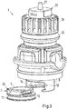
- Fig. 1 shows a first embodiment of a valve 1 according to the invention.
- Fig. 2 to 4 show parts of the valve 1 according to the first embodiment.
- the valve 1 comprises a valve housing 16 in which an inlet 3 as well as an outlet 2 are arranged.
- the valve 1 comprises a valve body 6 that is fixed to the housing 16.
- the valve body 6 comprises a presetting member 8 as well as a valve top 22.
- the valve top 22 holds the presetting member 8 in the housing 16.
- the valve 1 furthermore comprises a valve seat 4 as well as a valve element 5.
- the valve element 5 is displaceable along an axis A towards the valve seat 4 to throttle or stop a fluid flow through the valve seat 4.
- the valve seat 4 is arranged in a valve seat member 7.
- the valve seat member 7 is releasably connected to the valve body 6.
- the valve seat member 7 releasably connected to an axial end part 9 of the presetting member 8.
- the axial end part 9 as well as the valve seat member 7 are arranged in an insert 15.
- the insert 15 is arranged in the housing 16 and separates the inlet 3 and the outlet 2.
- the valve seat member 7 comprises a sealing groove 11 in which a sealing ring 12 is arranged.
- the sealing ring 12 provides a sealing between the insert 15 and the valve seat member 7.
- the valve seat member 7 furthermore comprises a snap-in groove 13 to facilitate a releasable connection of the valve seat member 7 and the valve body 6.
- the valve body 6 comprises a snap-in rim 14 that engages in the snap-in groove 13 to facilitate the releasable connection of the valve seat member 7 to the valve body 6.
- the valve seat member 7 is releasable from the valve body 6 by a displacement of the valve seat member 7 relative to the valve body 6 in a direction perpendicular to the axis A.
- valve seat member 7 Such a perpendicular motion of the valve seat member 7 is only possible when the valve body 6 together with the valve seat member 7 are removed from the housing 16.
- valve body 6 and the valve seat member 7 are arranged in the housing 16 and in particular in the insert 15 any displacement of the valve seat member 7 perpendicular to the axis A is blocked by the insert 15.
- the valve body 6 and in particular the presetting member 8 comprises a cutout 10 in a circumferential direction around the axis A.
- the cutout 10 allows the valve seat member 7 to be introduced into and released from the presetting member 8 as can be seen in detail in Fig. 2 and 3 .
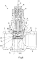
- Fig. 2 and 3 again show the first embodiment of the valve one according to the invention without the housing 16 and the insert 15.
- the valve 1 furthermore comprises a presetting mechanism.
- the presetting member 8 can be rotated using a presetting handle 19 to change the presetting of the valve 1.
- the valve seat member 7 and the axial end part 9 form an opening 18 in a tangential direction perpendicular to the axis A.
- the insert 15 comprises an aperture 17 adjacent to the opening 18. By rotating the valve seat member 7 and the presetting member 8 relative to the insert 15 the overlap of the aperture 17 and the opening 18 is changeable to adjust the effective flow cross section from the valve seat 4 to the outlet 2.
- the valve seat member 7 comprises a flow guiding surface 23 that is inclined relative to the axis A. Thereby the fluid flow from the valve seat 4 is guided through the aperture 17 and the opening 18 towards the outlet 2. Thereby pressure losses due to turbulence are reduced.
- the valve 1 furthermore comprises a stuffing box 20 through which a pin 21 is guided.
- the pin 21 can be engaged by an actuator attached to the valve 1 to open or close the valve 1.
- the axial position of the valve seat 4 is not necessarily fixed relative to the housing 16.
- the presetting of the valve 1 may also be changed by axially displacing the valve seat member 7.
- the effective flow cross section from the valve seat 4 to the outlet 2 may be changed due to a change in overlap between the aperture 17 and the opening 18.
- Fig. 4 and 5 show two different valve seat members 7.
- the valve seat member 7 according to Fig. 4 is used in the first embodiment as shown in Fig. 1 to 3 .
- the valve seat member 7 according to Fig. 5 is part of the valve 1 according to the second embodiment as shown in Fig. 6 and 7 .
- Fig. 4 and 5 each show a top view of a valve seat member 7.
- the difference between the valve seat members 7 according to the first and second embodiment is that the valve seat member 7 as shown in Fig. 5 additionally comprises a flow limitation 25 in flow direction between the valve seat 4 and the outlet 3.
- the flow limitation 25 reduces the effective flow cross section through a valve seat channel 24 from the inlet 3 to the valve seat 4.
- This has the advantage that the same valve 1 may be used for different applications by simply replacing the valve seat member 7. For example, one may use the valve 1 for two radiators of different size by simply replacing the valve seat member 7.
- Fig. 6 and 7 show the valve 1 according to the second embodiment of the invention. Corresponding features are denoted with the same reference signs as in the first embodiment according to Fig. 1 to 4 .
- the second embodiment uses a different valve seat member 7 compared to the first embodiment.
- the valve seat member 7 here comprises the flow limitation 25 in flow direction between the inlet 3 and the valve seat 4.
- the enlarged view of the valve 1 shown in Fig. 7 shows the overlap of the aperture 17 and the opening 18 in more detail.
- Both the aperture 17 and the opening 18 have a limited extend in the tangential direction perpendicular to the axis A.
Landscapes
- Engineering & Computer Science (AREA)
- General Engineering & Computer Science (AREA)
- Mechanical Engineering (AREA)
- Physics & Mathematics (AREA)
- Thermal Sciences (AREA)
- Chemical & Material Sciences (AREA)
- Combustion & Propulsion (AREA)
- Fluid Mechanics (AREA)
- Lift Valve (AREA)
Priority Applications (5)
| Application Number | Priority Date | Filing Date | Title |
|---|---|---|---|
| PL16151416T PL3193052T3 (pl) | 2016-01-15 | 2016-01-15 | Zawór i element gniazda zaworu |
| EP16151416.1A EP3193052B1 (en) | 2016-01-15 | 2016-01-15 | Valve with valve seat member |
| ES16151416T ES2739639T3 (es) | 2016-01-15 | 2016-01-15 | Válvula con miembro de asiento de válvula |
| RU2016150899A RU2655895C1 (ru) | 2016-01-15 | 2016-12-23 | Клапан и седельный элемент клапана |
| CN201710030513.0A CN106979343A (zh) | 2016-01-15 | 2017-01-16 | 阀和用于阀的阀座构件 |
Applications Claiming Priority (1)
| Application Number | Priority Date | Filing Date | Title |
|---|---|---|---|
| EP16151416.1A EP3193052B1 (en) | 2016-01-15 | 2016-01-15 | Valve with valve seat member |
Publications (2)
| Publication Number | Publication Date |
|---|---|
| EP3193052A1 EP3193052A1 (en) | 2017-07-19 |
| EP3193052B1 true EP3193052B1 (en) | 2019-05-08 |
Family
ID=55173788
Family Applications (1)
| Application Number | Title | Priority Date | Filing Date |
|---|---|---|---|
| EP16151416.1A Active EP3193052B1 (en) | 2016-01-15 | 2016-01-15 | Valve with valve seat member |
Country Status (5)
| Country | Link |
|---|---|
| EP (1) | EP3193052B1 (ru) |
| CN (1) | CN106979343A (ru) |
| ES (1) | ES2739639T3 (ru) |
| PL (1) | PL3193052T3 (ru) |
| RU (1) | RU2655895C1 (ru) |
Family Cites Families (10)
| Publication number | Priority date | Publication date | Assignee | Title |
|---|---|---|---|---|
| DE19647026A1 (de) * | 1996-11-14 | 1998-05-28 | Danfoss As | Heizkörperventil |
| DE19647027B4 (de) * | 1996-11-14 | 2004-12-02 | Danfoss A/S | Heizkörperventil |
| DE10022730A1 (de) * | 2000-05-10 | 2002-01-24 | Danfoss As | Einbauventil |
| JP5275277B2 (ja) * | 2010-03-15 | 2013-08-28 | 株式会社テイエルブイ | 調節弁 |
| JP5243513B2 (ja) * | 2010-10-25 | 2013-07-24 | Ckd株式会社 | 流体制御弁の弁座構造 |
| JP5432236B2 (ja) * | 2011-01-31 | 2014-03-05 | 株式会社鷺宮製作所 | 絞り弁装置 |
| CN102954226B (zh) * | 2011-08-18 | 2014-10-29 | 孙杰 | 减压节流阀 |
| DE202012003702U1 (de) * | 2012-04-07 | 2012-05-30 | TA Hydronics SA | Ventileinsatz für die Armatur eines Kompaktheizkörpers |
| DE202013001405U1 (de) * | 2013-02-13 | 2013-03-28 | TA Hydronics SA | Regelventileinsatz |
| JP6141663B2 (ja) * | 2013-03-27 | 2017-06-07 | 株式会社堀場エステック | 流体制御弁 |
-
2016
- 2016-01-15 PL PL16151416T patent/PL3193052T3/pl unknown
- 2016-01-15 EP EP16151416.1A patent/EP3193052B1/en active Active
- 2016-01-15 ES ES16151416T patent/ES2739639T3/es active Active
- 2016-12-23 RU RU2016150899A patent/RU2655895C1/ru active
-
2017
- 2017-01-16 CN CN201710030513.0A patent/CN106979343A/zh active Pending
Non-Patent Citations (1)
| Title |
|---|
| None * |
Also Published As
| Publication number | Publication date |
|---|---|
| EP3193052A1 (en) | 2017-07-19 |
| RU2655895C1 (ru) | 2018-05-29 |
| CN106979343A (zh) | 2017-07-25 |
| PL3193052T3 (pl) | 2019-11-29 |
| ES2739639T3 (es) | 2020-02-03 |
Similar Documents
| Publication | Publication Date | Title |
|---|---|---|
| AU2014231763B2 (en) | Water temperature regulating valve | |
| CN105909837A (zh) | 用于流动控制和调节的与压力无关的液压阀 | |
| ES2604809T3 (es) | Una válvula de control | |
| CN106200699B (zh) | 流量调节器单元 | |
| CA2379745C (en) | Sanitary mixing valve | |
| EP2089649B1 (en) | An adjustable regulator insert | |
| EP3193052B1 (en) | Valve with valve seat member | |
| EP3067601B1 (en) | Automatic balancing valve with preset flow rate | |
| FI70993B (fi) | Termostatkran | |
| EP3193051B1 (en) | Valve arrangement and insert for a valve arrangement | |
| EP3193064B1 (en) | Valve | |
| EP3919788B1 (en) | Mechanical fluid valve | |
| EP3193058B1 (en) | Valve | |
| RU2662653C2 (ru) | Клапан, в частности клапан теплообменника | |
| EP3627021B1 (en) | Valve with rotatable presetting element | |
| EP3193060B1 (en) | Valve, in particular heat exchanger valve | |
| RU2659865C2 (ru) | Клапанное устройство | |
| EP3193049A1 (en) | Valve | |
| EP4137721A1 (en) | Heat exchanger valve | |
| US3420440A (en) | Automatic balance valve for heat exchanging fluid | |
| EP3193047B1 (en) | Valve | |
| EP2567130B1 (en) | Thermostatic valve with improved pressure balancing | |
| EP3203345A1 (en) | Valve, in particular heat exchanger valve | |
| ITMI971720A1 (it) | Miscelatore termostatico |
Legal Events
| Date | Code | Title | Description |
|---|---|---|---|
| PUAI | Public reference made under article 153(3) epc to a published international application that has entered the european phase |
Free format text: ORIGINAL CODE: 0009012 |
|
| STAA | Information on the status of an ep patent application or granted ep patent |
Free format text: STATUS: THE APPLICATION HAS BEEN PUBLISHED |
|
| AK | Designated contracting states |
Kind code of ref document: A1 Designated state(s): AL AT BE BG CH CY CZ DE DK EE ES FI FR GB GR HR HU IE IS IT LI LT LU LV MC MK MT NL NO PL PT RO RS SE SI SK SM TR |
|
| AX | Request for extension of the european patent |
Extension state: BA ME |
|
| STAA | Information on the status of an ep patent application or granted ep patent |
Free format text: STATUS: REQUEST FOR EXAMINATION WAS MADE |
|
| 17P | Request for examination filed |
Effective date: 20180104 |
|
| RBV | Designated contracting states (corrected) |
Designated state(s): AL AT BE BG CH CY CZ DE DK EE ES FI FR GB GR HR HU IE IS IT LI LT LU LV MC MK MT NL NO PL PT RO RS SE SI SK SM TR |
|
| GRAP | Despatch of communication of intention to grant a patent |
Free format text: ORIGINAL CODE: EPIDOSNIGR1 |
|
| STAA | Information on the status of an ep patent application or granted ep patent |
Free format text: STATUS: GRANT OF PATENT IS INTENDED |
|
| INTG | Intention to grant announced |
Effective date: 20181023 |
|
| GRAS | Grant fee paid |
Free format text: ORIGINAL CODE: EPIDOSNIGR3 |
|
| GRAA | (expected) grant |
Free format text: ORIGINAL CODE: 0009210 |
|
| STAA | Information on the status of an ep patent application or granted ep patent |
Free format text: STATUS: THE PATENT HAS BEEN GRANTED |
|
| AK | Designated contracting states |
Kind code of ref document: B1 Designated state(s): AL AT BE BG CH CY CZ DE DK EE ES FI FR GB GR HR HU IE IS IT LI LT LU LV MC MK MT NL NO PL PT RO RS SE SI SK SM TR |
|
| REG | Reference to a national code |
Ref country code: GB Ref legal event code: FG4D |
|
| REG | Reference to a national code |
Ref country code: CH Ref legal event code: EP Ref country code: AT Ref legal event code: REF Ref document number: 1130652 Country of ref document: AT Kind code of ref document: T Effective date: 20190515 |
|
| REG | Reference to a national code |
Ref country code: DE Ref legal event code: R096 Ref document number: 602016013387 Country of ref document: DE Ref country code: IE Ref legal event code: FG4D |
|
| REG | Reference to a national code |
Ref country code: NL Ref legal event code: MP Effective date: 20190508 |
|
| REG | Reference to a national code |
Ref country code: LT Ref legal event code: MG4D |
|
| PG25 | Lapsed in a contracting state [announced via postgrant information from national office to epo] |
Ref country code: FI Free format text: LAPSE BECAUSE OF FAILURE TO SUBMIT A TRANSLATION OF THE DESCRIPTION OR TO PAY THE FEE WITHIN THE PRESCRIBED TIME-LIMIT Effective date: 20190508 Ref country code: LT Free format text: LAPSE BECAUSE OF FAILURE TO SUBMIT A TRANSLATION OF THE DESCRIPTION OR TO PAY THE FEE WITHIN THE PRESCRIBED TIME-LIMIT Effective date: 20190508 Ref country code: HR Free format text: LAPSE BECAUSE OF FAILURE TO SUBMIT A TRANSLATION OF THE DESCRIPTION OR TO PAY THE FEE WITHIN THE PRESCRIBED TIME-LIMIT Effective date: 20190508 Ref country code: SE Free format text: LAPSE BECAUSE OF FAILURE TO SUBMIT A TRANSLATION OF THE DESCRIPTION OR TO PAY THE FEE WITHIN THE PRESCRIBED TIME-LIMIT Effective date: 20190508 Ref country code: NO Free format text: LAPSE BECAUSE OF FAILURE TO SUBMIT A TRANSLATION OF THE DESCRIPTION OR TO PAY THE FEE WITHIN THE PRESCRIBED TIME-LIMIT Effective date: 20190808 Ref country code: PT Free format text: LAPSE BECAUSE OF FAILURE TO SUBMIT A TRANSLATION OF THE DESCRIPTION OR TO PAY THE FEE WITHIN THE PRESCRIBED TIME-LIMIT Effective date: 20190908 Ref country code: AL Free format text: LAPSE BECAUSE OF FAILURE TO SUBMIT A TRANSLATION OF THE DESCRIPTION OR TO PAY THE FEE WITHIN THE PRESCRIBED TIME-LIMIT Effective date: 20190508 Ref country code: NL Free format text: LAPSE BECAUSE OF FAILURE TO SUBMIT A TRANSLATION OF THE DESCRIPTION OR TO PAY THE FEE WITHIN THE PRESCRIBED TIME-LIMIT Effective date: 20190508 |
|
| PG25 | Lapsed in a contracting state [announced via postgrant information from national office to epo] |
Ref country code: BG Free format text: LAPSE BECAUSE OF FAILURE TO SUBMIT A TRANSLATION OF THE DESCRIPTION OR TO PAY THE FEE WITHIN THE PRESCRIBED TIME-LIMIT Effective date: 20190808 Ref country code: RS Free format text: LAPSE BECAUSE OF FAILURE TO SUBMIT A TRANSLATION OF THE DESCRIPTION OR TO PAY THE FEE WITHIN THE PRESCRIBED TIME-LIMIT Effective date: 20190508 Ref country code: LV Free format text: LAPSE BECAUSE OF FAILURE TO SUBMIT A TRANSLATION OF THE DESCRIPTION OR TO PAY THE FEE WITHIN THE PRESCRIBED TIME-LIMIT Effective date: 20190508 Ref country code: GR Free format text: LAPSE BECAUSE OF FAILURE TO SUBMIT A TRANSLATION OF THE DESCRIPTION OR TO PAY THE FEE WITHIN THE PRESCRIBED TIME-LIMIT Effective date: 20190809 |
|
| PG25 | Lapsed in a contracting state [announced via postgrant information from national office to epo] |
Ref country code: SK Free format text: LAPSE BECAUSE OF FAILURE TO SUBMIT A TRANSLATION OF THE DESCRIPTION OR TO PAY THE FEE WITHIN THE PRESCRIBED TIME-LIMIT Effective date: 20190508 Ref country code: RO Free format text: LAPSE BECAUSE OF FAILURE TO SUBMIT A TRANSLATION OF THE DESCRIPTION OR TO PAY THE FEE WITHIN THE PRESCRIBED TIME-LIMIT Effective date: 20190508 Ref country code: EE Free format text: LAPSE BECAUSE OF FAILURE TO SUBMIT A TRANSLATION OF THE DESCRIPTION OR TO PAY THE FEE WITHIN THE PRESCRIBED TIME-LIMIT Effective date: 20190508 Ref country code: DK Free format text: LAPSE BECAUSE OF FAILURE TO SUBMIT A TRANSLATION OF THE DESCRIPTION OR TO PAY THE FEE WITHIN THE PRESCRIBED TIME-LIMIT Effective date: 20190508 Ref country code: CZ Free format text: LAPSE BECAUSE OF FAILURE TO SUBMIT A TRANSLATION OF THE DESCRIPTION OR TO PAY THE FEE WITHIN THE PRESCRIBED TIME-LIMIT Effective date: 20190508 |
|
| REG | Reference to a national code |
Ref country code: ES Ref legal event code: FG2A Ref document number: 2739639 Country of ref document: ES Kind code of ref document: T3 Effective date: 20200203 |
|
| REG | Reference to a national code |
Ref country code: DE Ref legal event code: R097 Ref document number: 602016013387 Country of ref document: DE |
|
| PG25 | Lapsed in a contracting state [announced via postgrant information from national office to epo] |
Ref country code: SM Free format text: LAPSE BECAUSE OF FAILURE TO SUBMIT A TRANSLATION OF THE DESCRIPTION OR TO PAY THE FEE WITHIN THE PRESCRIBED TIME-LIMIT Effective date: 20190508 |
|
| PLBE | No opposition filed within time limit |
Free format text: ORIGINAL CODE: 0009261 |
|
| STAA | Information on the status of an ep patent application or granted ep patent |
Free format text: STATUS: NO OPPOSITION FILED WITHIN TIME LIMIT |
|
| 26N | No opposition filed |
Effective date: 20200211 |
|
| REG | Reference to a national code |
Ref country code: AT Ref legal event code: UEP Ref document number: 1130652 Country of ref document: AT Kind code of ref document: T Effective date: 20190508 |
|
| PG25 | Lapsed in a contracting state [announced via postgrant information from national office to epo] |
Ref country code: SI Free format text: LAPSE BECAUSE OF FAILURE TO SUBMIT A TRANSLATION OF THE DESCRIPTION OR TO PAY THE FEE WITHIN THE PRESCRIBED TIME-LIMIT Effective date: 20190508 |
|
| PG25 | Lapsed in a contracting state [announced via postgrant information from national office to epo] |
Ref country code: MC Free format text: LAPSE BECAUSE OF FAILURE TO SUBMIT A TRANSLATION OF THE DESCRIPTION OR TO PAY THE FEE WITHIN THE PRESCRIBED TIME-LIMIT Effective date: 20190508 |
|
| REG | Reference to a national code |
Ref country code: CH Ref legal event code: PL |
|
| REG | Reference to a national code |
Ref country code: BE Ref legal event code: MM Effective date: 20200131 |
|
| PG25 | Lapsed in a contracting state [announced via postgrant information from national office to epo] |
Ref country code: LU Free format text: LAPSE BECAUSE OF NON-PAYMENT OF DUE FEES Effective date: 20200115 |
|
| PG25 | Lapsed in a contracting state [announced via postgrant information from national office to epo] |
Ref country code: BE Free format text: LAPSE BECAUSE OF NON-PAYMENT OF DUE FEES Effective date: 20200131 Ref country code: CH Free format text: LAPSE BECAUSE OF NON-PAYMENT OF DUE FEES Effective date: 20200131 Ref country code: LI Free format text: LAPSE BECAUSE OF NON-PAYMENT OF DUE FEES Effective date: 20200131 |
|
| PG25 | Lapsed in a contracting state [announced via postgrant information from national office to epo] |
Ref country code: IE Free format text: LAPSE BECAUSE OF NON-PAYMENT OF DUE FEES Effective date: 20200115 |
|
| PG25 | Lapsed in a contracting state [announced via postgrant information from national office to epo] |
Ref country code: MT Free format text: LAPSE BECAUSE OF FAILURE TO SUBMIT A TRANSLATION OF THE DESCRIPTION OR TO PAY THE FEE WITHIN THE PRESCRIBED TIME-LIMIT Effective date: 20190508 Ref country code: CY Free format text: LAPSE BECAUSE OF FAILURE TO SUBMIT A TRANSLATION OF THE DESCRIPTION OR TO PAY THE FEE WITHIN THE PRESCRIBED TIME-LIMIT Effective date: 20190508 |
|
| PG25 | Lapsed in a contracting state [announced via postgrant information from national office to epo] |
Ref country code: MK Free format text: LAPSE BECAUSE OF FAILURE TO SUBMIT A TRANSLATION OF THE DESCRIPTION OR TO PAY THE FEE WITHIN THE PRESCRIBED TIME-LIMIT Effective date: 20190508 Ref country code: IS Free format text: LAPSE BECAUSE OF FAILURE TO SUBMIT A TRANSLATION OF THE DESCRIPTION OR TO PAY THE FEE WITHIN THE PRESCRIBED TIME-LIMIT Effective date: 20190908 |
|
| P01 | Opt-out of the competence of the unified patent court (upc) registered |
Effective date: 20230617 |
|
| PGFP | Annual fee paid to national office [announced via postgrant information from national office to epo] |
Ref country code: GB Payment date: 20231207 Year of fee payment: 9 |
|
| PGFP | Annual fee paid to national office [announced via postgrant information from national office to epo] |
Ref country code: FR Payment date: 20231222 Year of fee payment: 9 |
|
| PGFP | Annual fee paid to national office [announced via postgrant information from national office to epo] |
Ref country code: PL Payment date: 20231215 Year of fee payment: 9 |
|
| PGFP | Annual fee paid to national office [announced via postgrant information from national office to epo] |
Ref country code: ES Payment date: 20240208 Year of fee payment: 9 |
|
| PGFP | Annual fee paid to national office [announced via postgrant information from national office to epo] |
Ref country code: AT Payment date: 20231227 Year of fee payment: 9 |
|
| PGFP | Annual fee paid to national office [announced via postgrant information from national office to epo] |
Ref country code: DE Payment date: 20231205 Year of fee payment: 9 |
|
| PGFP | Annual fee paid to national office [announced via postgrant information from national office to epo] |
Ref country code: TR Payment date: 20240111 Year of fee payment: 9 Ref country code: IT Payment date: 20231212 Year of fee payment: 9 |