EP3192903A1 - Dispositif de gestion de fils - Google Patents
Dispositif de gestion de fils Download PDFInfo
- Publication number
- EP3192903A1 EP3192903A1 EP16305031.3A EP16305031A EP3192903A1 EP 3192903 A1 EP3192903 A1 EP 3192903A1 EP 16305031 A EP16305031 A EP 16305031A EP 3192903 A1 EP3192903 A1 EP 3192903A1
- Authority
- EP
- European Patent Office
- Prior art keywords
- drum
- axis
- wire
- rotation
- management device
- Prior art date
- Legal status (The legal status is an assumption and is not a legal conclusion. Google has not performed a legal analysis and makes no representation as to the accuracy of the status listed.)
- Granted
Links
Images


Classifications
-
- D—TEXTILES; PAPER
- D02—YARNS; MECHANICAL FINISHING OF YARNS OR ROPES; WARPING OR BEAMING
- D02G—CRIMPING OR CURLING FIBRES, FILAMENTS, THREADS, OR YARNS; YARNS OR THREADS
- D02G1/00—Producing crimped or curled fibres, filaments, yarns, or threads, giving them latent characteristics
- D02G1/02—Producing crimped or curled fibres, filaments, yarns, or threads, giving them latent characteristics by twisting, fixing the twist and backtwisting, i.e. by imparting false twist
- D02G1/0206—Producing crimped or curled fibres, filaments, yarns, or threads, giving them latent characteristics by twisting, fixing the twist and backtwisting, i.e. by imparting false twist by false-twisting
- D02G1/0266—Producing crimped or curled fibres, filaments, yarns, or threads, giving them latent characteristics by twisting, fixing the twist and backtwisting, i.e. by imparting false twist by false-twisting false-twisting machines
-
- D—TEXTILES; PAPER
- D02—YARNS; MECHANICAL FINISHING OF YARNS OR ROPES; WARPING OR BEAMING
- D02G—CRIMPING OR CURLING FIBRES, FILAMENTS, THREADS, OR YARNS; YARNS OR THREADS
- D02G1/00—Producing crimped or curled fibres, filaments, yarns, or threads, giving them latent characteristics
- D02G1/02—Producing crimped or curled fibres, filaments, yarns, or threads, giving them latent characteristics by twisting, fixing the twist and backtwisting, i.e. by imparting false twist
- D02G1/0206—Producing crimped or curled fibres, filaments, yarns, or threads, giving them latent characteristics by twisting, fixing the twist and backtwisting, i.e. by imparting false twist by false-twisting
-
- D—TEXTILES; PAPER
- D02—YARNS; MECHANICAL FINISHING OF YARNS OR ROPES; WARPING OR BEAMING
- D02G—CRIMPING OR CURLING FIBRES, FILAMENTS, THREADS, OR YARNS; YARNS OR THREADS
- D02G1/00—Producing crimped or curled fibres, filaments, yarns, or threads, giving them latent characteristics
- D02G1/02—Producing crimped or curled fibres, filaments, yarns, or threads, giving them latent characteristics by twisting, fixing the twist and backtwisting, i.e. by imparting false twist
-
- D—TEXTILES; PAPER
- D02—YARNS; MECHANICAL FINISHING OF YARNS OR ROPES; WARPING OR BEAMING
- D02G—CRIMPING OR CURLING FIBRES, FILAMENTS, THREADS, OR YARNS; YARNS OR THREADS
- D02G1/00—Producing crimped or curled fibres, filaments, yarns, or threads, giving them latent characteristics
- D02G1/02—Producing crimped or curled fibres, filaments, yarns, or threads, giving them latent characteristics by twisting, fixing the twist and backtwisting, i.e. by imparting false twist
- D02G1/04—Devices for imparting false twist
-
- D—TEXTILES; PAPER
- D02—YARNS; MECHANICAL FINISHING OF YARNS OR ROPES; WARPING OR BEAMING
- D02G—CRIMPING OR CURLING FIBRES, FILAMENTS, THREADS, OR YARNS; YARNS OR THREADS
- D02G1/00—Producing crimped or curled fibres, filaments, yarns, or threads, giving them latent characteristics
- D02G1/02—Producing crimped or curled fibres, filaments, yarns, or threads, giving them latent characteristics by twisting, fixing the twist and backtwisting, i.e. by imparting false twist
- D02G1/04—Devices for imparting false twist
- D02G1/08—Rollers or other friction causing elements
-
- D—TEXTILES; PAPER
- D02—YARNS; MECHANICAL FINISHING OF YARNS OR ROPES; WARPING OR BEAMING
- D02G—CRIMPING OR CURLING FIBRES, FILAMENTS, THREADS, OR YARNS; YARNS OR THREADS
- D02G1/00—Producing crimped or curled fibres, filaments, yarns, or threads, giving them latent characteristics
- D02G1/12—Producing crimped or curled fibres, filaments, yarns, or threads, giving them latent characteristics using stuffer boxes
-
- D—TEXTILES; PAPER
- D02—YARNS; MECHANICAL FINISHING OF YARNS OR ROPES; WARPING OR BEAMING
- D02G—CRIMPING OR CURLING FIBRES, FILAMENTS, THREADS, OR YARNS; YARNS OR THREADS
- D02G1/00—Producing crimped or curled fibres, filaments, yarns, or threads, giving them latent characteristics
- D02G1/20—Combinations of two or more of the above-mentioned operations or devices; After-treatments for fixing crimp or curl
- D02G1/205—After-treatments for fixing crimp or curl
Definitions
- the present invention relates to the field of son management mechanisms in a processing system and more particularly to the field of son management mechanisms upstream of a heat treatment interface.
- the present invention aims to overcome these disadvantages by proposing a solution that eliminates this problem of homogeneity between the different son treated.
- the subject of the invention is thus a device for managing yarns in a yarn processing line downstream of a curling box and upstream of a means for thermal fixation of the crimp, said device comprising a fixed support, inlet of the curling box being formed by one or more crimping rolls for feeding at least one wire into the curling box, characterized in that the device comprises at least one axial drum positioned upstream of the fastening means thermal, the drum being traversed by a wire in the curling box and mounted on the fixed support of the device so as to operate a substantially axial rotation for generating at least one false twist to the treated son.
- the invention also relates to a method for managing yarns in a yarn processing line, characterized in that it comprises a step of generating at least one false twist of the yarns during the passage of the yarns in a drum, prior to a step of thermal fixing of the son.
- the present invention relates to a device 1 for managing yarns in a line for processing yarns downstream of a curling box 2 and upstream of a means for thermal fixation of the curl, said device 1 comprising a fixed support 3 , the inlet of the curling box 2 being formed by one or more crimping rolls 7 for feeding at least one thread into the curling box 2, characterized in that the device 1 comprises at least one axial drum 4 positioned upstream of the thermal fixing means, the drum 4 being traversed by a wire in the curling box 2 and mounted on the fixed support 3 of the device 1 so as to operate a substantially axial rotation to generate at least one false twist to treated son.
- the son In their crossing of the axial drum 4, the son are without tension.
- the latch by rotation of the drum 4 allows a change in the distribution of the portion of the son present in the drum within the son strand that joins them.
- This modification of the distribution of the son by the drum 4 in the treatment line thus allows a reorganization of the son within of the strand over their entire respective length.
- the generation of this false twist allows different portions of the same wire to be arranged differently along the treatment line, for example on the conveyor belt, and in particular at each of the thread processing stages. with the other wires of the strand.
- the invention also relates to a method for managing yarns in a yarn processing line, characterized in that it comprises a step of generating at least one false twist of the yarns during the passage of the yarns in a drum, prior to a heat fixing step son.
- the wire management device 1 is characterized in that the drum 4 is mounted on the fixed support 3 of the device 1 and arranged to operate a rotary pendular movement around the axis of the drum 4.
- the drum 4 is associated with a drive means 5 for driving in rotation.
- This association can be achieved by any known mechanism for example a drive belt or a gear.
- the axis of rotation of the drum 4 is oriented along a substantially horizontal axis. According to this construction, the displacement of the son through the drum 4 is generated either upstream by the arrival of the son by the feeding rack which operates a stuffing in the drum 4 pendulum swing, or downstream by pulling the son deposited on a drive means, for example a treadmill, or a combination of these two phenomena.
- the pendulum swing of the drum 4 makes it possible to limit or eliminate the tensions on the wires when they are pulled by the drive means downstream of the drum 4.
- the axis of rotation of the drum 4 is oriented along an axis providing an inclination with respect to a horizontal axis.
- this inclination is made from a high point upstream of the drum 4 to a low point downstream of the drum 4.
- Such inclination makes it easier to move the threads through the drum 4 from a high point to a low point by taking advantage of of the gravity of the wires which constitute the strand which crosses the drum 4.
- the invention also relates more specifically to the drum 4 adapted to allow the generation of a false twist on the various son passing through it.
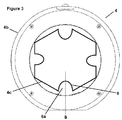
- the drum 4 of the invention has a substantially cylindrical body 4a with a circular or oval section.
- this shape could be of polygonal section, for example pentagonal, hexagonal or octagonal.
- the drum 4 of the invention is characterized in that the inner surface 4c of the body 4a of the drum 4 has a substantially conical shape.
- the conical arrangement is preferably arranged from a restricted upstream opening to a wide downstream opening. Such an arrangement makes it possible to perform a facilitated installation at the outlet of the drum 4, for example at a precise point of a drive means such as a conveyor belt.
- the body 4a of the drum 4 has a substantially axial tubular shape.
- this axis of the body 4a of the drum 4 may be different from the axis of rotation of the drum 4 during its operation for the generation of false twists.
- the axis of rotation of the drum 4 coincides with the axis of the body 4a of the drum 4.
- the drum 4 is characterized in that it comprises at least one gripping surface 6 made by at least one relief of the inner surface in a section perpendicular to the axis of the drum 4.
- This surface d 6 grip participates in the rotational training of the son to allow to generate false twists, together with the rotation of the drum 4.
- the grip surface 6 must however allow the sliding of the son through the body 4a of the drum 4.
- this gripping surface 6 is made continuously along the length of the inner surface 4c of the drum 4 between the upstream opening 4d and the downstream opening 4e.
- This gripping surface 6 can also be continuous or discontinuous along the periphery of the inner surface 4c of the drum 4.
- this gripping surface 6 is made by a rough surface, for example of emery-type deposited on all or part of the inner surface 4c of the body 4a of the drum 4.
- the drum 4 is characterized in that it comprises at least one gripping surface 6 made by at least one relief 6a of the inner surface 4c.
- This relief 6a which exceeds the inner surface 4c allows a rotation drive of the various son with the drum 4 at the portion of son that passes through the drum 4.
- This relief 6a may be specific to a training in rotation of the threads according to a particular direction of rotation of the drum 4.
- the relief 6a which forms this gripping surface 6 in the drum 4 is arranged so as to achieve a continuous relief 6a along the length of the inner surface 4c of the drum 4 between the upstream opening 4d and the opening swallows 4th.
- the relief 6a is constructed to have a variation of its height between a greater height at a point near the upstream opening 4d and a smaller height at a nearby point. from the opening swallows 4th.
- the relief 6a comprises an axis of symmetry S which intersects the axis of rotation of the drum 4 in a section perpendicular to the axis of the drum structure 4.
- the embodiment a relief 6a comprising such a symmetry makes it possible to operate a rotation of the various son by the drum 4 which is identical in both directions of rotation of the drum 4. Such a construction thus facilitates the generation of homogeneous false twists at the level different wires moving in the drum 4.
- the inner surface 4c of the body 4a of the drum 4 comprises at least two gripping surfaces 6 of at least one wire.
- the multiplication of the number of gripping surfaces 6 of the thread inside the drum 4 makes it possible to optimize the rotation of the threads with the rocker of the drum 4.
- the drum 4 of the invention is adapted to be integrated in a son of management device 1 according to the invention.
Landscapes
- Engineering & Computer Science (AREA)
- Mechanical Engineering (AREA)
- Textile Engineering (AREA)
- Yarns And Mechanical Finishing Of Yarns Or Ropes (AREA)
- Preliminary Treatment Of Fibers (AREA)
Abstract
Description
- La présente invention se rapporte au domaine des mécanismes de gestion de fils dans un système de traitement et plus particulièrement au domaine des mécanismes de gestion de fils en amont d'une interface de traitement thermique.
- Actuellement, lors d'un traitement conjoint de plusieurs fils, l'ensemble des fils traités, provenant de plusieurs bobines, sont réunis pour réaliser un toron.
- Cependant, suite aux différentes opérations de traitement effectuées sur ce toron de fils traités simultanément, il a été observé que pour un même toron traité, certains fils présentent des divergences de qualités soulevant un problème dans l'homogénéité du traitement des fils par le dispositif.
- La présente invention a pour but de pallier ces inconvénients en proposant une solution qui permet de supprimer ce problème d'homogénéité entre les différents fils traités.
- L'invention a ainsi pour objet un dispositif de gestion de fils dans une ligne de traitement de fils en aval d'une boîte à friser et en amont d'un moyen de fixation thermique de la frisure, ledit dispositif comprenant un support fixe, l'entrée de la boîte à friser étant formée par un ou plusieurs rouleaux de frisure d'amenée d'au moins un fil dans la boîte à friser, caractérisé en ce que le dispositif comprend au moins un tambour axial positionné en amont du moyen de fixation thermique, le tambour étant traversé par un fil dans la boite à friser et monté sur le support fixe du dispositif de façon à opérer une rotation sensiblement axiale permettant de générer au moins une fausse torsion aux fils traités.
- L'invention porte aussi sur un tambour caractérisé en ce qu'il comprend :
- un corps sensiblement axial et tubulaire comprenant, d'une part, une surface extérieure et, d'autre part, une surface intérieure, ainsi qu'au moins une ouverture au niveau de chacune de ses extrémités, ces ouvertures étant aptes à permettre le passage d'au moins fil,
- au moins une interface de montage du corps du tambour sur un bâti autorisant la rotation du corps du tambour autour d'un axe,
- au moins une surface d'accroche d'au moins un fil, disposée sur la surface intérieure du corps du tambour et apte à permettre l'entrainement en rotation d'au moins un fil avec le corps du tambour.
- L'invention concerne également un procédé de gestion de fils dans une ligne de traitement de fils, caractérisé en ce qu'il comprend une étape de génération d'au moins une fausse torsion des fils lors du passage des fils dans un tambour, préalablement à une étape de fixation thermique des fils.
- L'invention sera mieux comprise, grâce à la description ci-après, qui se rapporte à un mode de réalisation préféré, donné à titre d'exemple non limitatif, et expliqué avec référence aux dessins schématiques annexés, dans lesquels :
- la
figure 1 est une représentation schématique d'un exemple de dispositif de gestion de fils selon l'invention dans laquelle les flèches indiquent le sens de déplacement des fils, - la
figure 2 est une représentation schématique d'un premier exemple de tambour selon l'invention, - la
figure 3 est une représentation schématique d'un second exemple de tambour selon l'invention. - La présente invention porte sur un dispositif de gestion 1 de fils dans une ligne de traitement de fils en aval d'une boîte à friser 2 et en amont d'un moyen de fixation thermique de la frisure, ledit dispositif 1 comprenant un support 3 fixe, l'entrée de la boîte à friser 2 étant formée par un ou plusieurs rouleaux de frisure 7 d'amenée d'au moins un fil dans la boîte à friser 2, caractérisé en ce que le dispositif 1 comprend au moins un tambour 4 axial positionné en amont du moyen de fixation thermique, le tambour 4 étant traversé par un fil dans la boite à friser 2 et monté sur le support 3 fixe du dispositif 1 de façon à opérer une rotation sensiblement axiale permettant de générer au moins une fausse torsion aux fils traités.
- La génération d'une fausse torsion à l'ensemble des fils destinés à subir un traitement thermique permet une homogénéisation de la répartition de ces fils lors de leur pose dans le moyen de fixation thermique.
- Dans leur traversée du tambour axial 4, les fils sont sans tension. La bascule par rotation du tambour 4 permet une modification de la répartition de la portion des fils présent dans le tambour au sein du toron de fils qui les réunit. Cette modification de la répartition des fils par le tambour 4 dans la ligne de traitement permet ainsi une réorganisation des fils au sein du toron sur l'ensemble de leur longueur respective. De même, la génération de cette fausse torsion permet à différentes portions d'un même fil d'être disposées différemment le long de la ligne de traitement, par exemple sur le tapis transporteur, et notamment au niveau de chacune des étapes de traitement du fil avec les autres fils du toron.
- Ainsi l'invention porte également sur un procédé de gestion de fils dans une ligne de traitement de fils, caractérisé en ce qu'il comprend une étape de génération d'au moins une fausse torsion des fils lors du passage des fils dans un tambour, préalablement à une étape de fixation thermique des fils.
- Une rotation anarchique du tambour 4 permettrait d'aboutir à un résultat de similaire dans l'homogénéisation du traitement des fils au sein du toron. Toutefois, la génération d'une fausse torsion par le tambour 4 présente comme avantages supplémentaires, d'une part, d'éviter un emmêlement des différents fils d'un même toron et, d'autre part, de permettre un démêlage facilité lors de l'opération de bobinage en fin de traitement. Aussi, selon une particularité de construction, le dispositif de gestion 1 de fils selon l'invention est caractérisé en ce que le tambour 4 est monté sur le support 3 fixe du dispositif 1 et arrangé pour opérer un mouvement rotatif pendulaire autour de l'axe du tambour 4.
- Selon un exemple de construction préféré du dispositif de gestion 1 de l'invention, le tambour 4 est associé à un moyen moteur 5 d'entraînement en rotation. Cette association peut être réalisée par tout mécanisme connu par exemple une courroie d'entraînement ou un engrenage.
- Selon une particularité de construction du dispositif complémentaire, l'axe de rotation du tambour 4 est orienté selon un axe sensiblement horizontal. Selon cette construction, le déplacement des fils au travers du tambour 4 est généré soit en amont par l'arrivée des fils par le râtelier d'alimentation qui opère un bourrage dans le tambour 4 en bascule pendulaire, soit en aval par une traction des fils déposés sur un moyen d'entraînement, par exemple un tapis roulant, soit encore une combinaison de ces deux phénomènes.
- Il convient de noter que la bascule pendulaire du tambour 4 permet de limiter voire supprimer les tensions sur les fils lorsque ceux-ci sont tractés par le moyen d'entraînement en aval du tambour 4.
- Selon une alternative de construction à cette particularité, l'axe de rotation du tambour 4 est orienté selon un axe réalisant une inclinaison par rapport à un axe horizontal. Préférentiellement, cette inclinaison est réalisée depuis un point haut en amont du tambour 4 vers un point bas en aval du tambour 4. Une telle inclinaison permet de faciliter le déplacement des fils au travers du tambour 4 depuis un point haut vers un point bas en profitant de la gravité des fils qui constituent le toron qui traverse le tambour 4.
- L'invention porte aussi plus spécifiquement sur le tambour 4 adapté pour permettre la génération d'une fausse torsion sur les différents fils qui le traversent.
- Le tambour 4 selon l'invention est ainsi caractérisé en ce qu'il comprend :
- un corps 4a sensiblement axial et tubulaire comprenant, d'une part, une surface extérieure 4b et, d'autre part, une surface intérieure 4c, ainsi qu'au moins une ouverture 4d, 4e au niveau de chacune de ses extrémités, ces ouvertures 4d, 4e étant aptes à permettre le passage d'au moins fil,
- au moins une interface de montage du corps du tambour 4 sur un bâti 3 autorisant la rotation du corps 4a du tambour 4 autour d'un axe,
- au moins une surface d'accroche 6 d'au moins un fil, disposée sur la surface intérieure 4c du corps 4a du tambour 4 et apte à permettre l'entrainement en rotation d'au moins un fil avec le corps 4a du tambour 4.
- Selon un mode de construction préféré, le tambour 4 de l'invention présente un corps 4a de forme sensiblement cylindrique avec une section circulaire ou ovale. Toutefois, cette forme pourrait être de section polygonale, par exemple pentagonale, hexagonale ou octogonale.
- De façon alternative ou complémentaire, le tambour 4 de l'invention est caractérisé en ce que la surface intérieure 4c du corps 4a du tambour 4 présente une forme sensiblement conique. L'arrangement conique est préférentiellement disposé depuis une ouverture amont restreinte vers une ouverture avale large. Un tel arrangement permet d'opérer une pose facilitée en sortie du tambour 4, par exemple au niveau d'un point précis d'un moyen d'entraînement tel qu'un tapis roulant.
- Selon une particularité de construction, le corps 4a du tambour 4 présente une forme tubulaire sensiblement axiale. Toutefois, cet axe du corps 4a du tambour 4 peut être différent de l'axe de rotation du tambour 4 lors de son fonctionnement pour la génération de fausses torsions. Cependant, selon un mode de construction préférentielle, l'axe de rotation du tambour 4 est confondu avec l'axe du corps 4a du tambour 4.
- Selon une particularité de construction, le tambour 4 est caractérisé en ce qu'il comprend au moins une surface d'accroche 6 réalisée par au moins un relief de la surface intérieure dans une section perpendiculaire à l'axe du tambour 4. Cette surface d'accroche 6 participe à l'entrainement en rotation des fils pour permettre d'y générer des fausses torsions, conjointement avec la rotation du tambour 4. Outre l'entrainement en rotation, cette surface d'accroche 6 doit cependant autoriser le glissement des fils au travers du corps 4a du tambour 4.
- Préférentiellement, cette surface d'accroche 6 est réalisée de façon continue sur la longueur de la surface intérieure 4c du tambour 4 entre l'ouverture amont 4d et l'ouverture avale 4e. Cette surface d'accroche 6 peut également être continue ou discontinue le long du pourtour de la surface intérieure 4c du tambour 4.
- Selon une première particularité de construction non-limitative de l'invention, cette surface d'accroche 6 est réalisée par une surface rugueuse, par exemple de type toile émeri déposée sur tout ou partie de la surface intérieure 4c du corps 4a du tambour 4.
- Selon une autre particularité de construction, éventuellement complémentaire de la particularité précédente, le tambour 4 est caractérisé en ce qu'il comprend au moins une surface d'accroche 6 réalisée par au moins un relief 6a de la surface intérieure 4c. Ce relief 6a qui réalise un dépassement par rapport à la surface intérieure 4c permet un entraînement en rotation des différents fils avec le tambour 4 au niveau de la portion de fils qui traverse ce tambour 4. Ce relief 6a peut être spécifique d'un entraînement en rotation des fils selon un sens particulier de rotation du tambour 4.
- Selon une construction préférentielle de cette particularité, le relief 6a qui forme cette surface d'accroche 6 dans le tambour 4 est disposé de façon à réaliser un relief 6a continu sur la longueur de la surface intérieure 4c du tambour 4 entre l'ouverture amont 4d et l'ouverture avale 4e. De façon alternative, le relief 6a est construit de façon à présenter une variation de sa hauteur entre une hauteur plus importante au niveau d'un point à proximité de l'ouverture amont 4d et une hauteur moins importante au niveau d'un point à proximité de l'ouverture avale 4e.
- Toutefois, selon une spécificité de cette particularité de construction, le relief 6a comprenant un axe de symétrie S qui réalise une intersection avec l'axe de rotation du tambour 4 dans une section perpendiculaire à l'axe de la structure du tambour 4. La réalisation d'un relief 6a comprenant une telle symétrie permet d'opérer un entraînement en rotation des différents fils par le tambour 4 qui soit identique dans les deux sens de rotation du tambour 4. Une telle construction facilite ainsi la génération de fausses torsions homogènes au niveau des différents fils en déplacement dans le tambour 4.
- Selon une particularité de construction du tambour 4, la surface intérieure 4c du corps 4a du tambour 4 comprend au moins deux surfaces d'accroche 6 d'au moins un fil. La multiplication du nombre de surfaces d'accroche 6 du fil à l'intérieur du tambour 4 permet une optimisation de l'entraînement en rotation des fils avec la bascule du tambour 4.
- Selon un mode de construction préférée, le tambour 4 de l'invention est adapté pour être intégré dans un dispositif de gestion 1 de fils selon l'invention.
- Bien entendu, l'invention n'est pas limitée au mode de réalisation décrit et représenté aux dessins annexés. Des modifications restent possibles, notamment du point de vue de la constitution des divers éléments ou par substitution d'équivalents techniques, sans sortir pour autant du domaine de protection de l'invention.
Claims (15)
- Dispositif de gestion (1) de fils dans une ligne de traitement de fils en aval d'une boîte à friser (2) et en amont d'un moyen de fixation thermique de la frisure, ledit dispositif (1) comprenant un support (3) fixe, l'entrée de la boîte à friser (2) étant formée par un ou plusieurs rouleaux de frisure (7) d'amenée d'au moins un fil dans la boîte à friser (2), caractérisé en ce que le dispositif (1) comprend au moins un tambour (4) axial positionné en amont du moyen de fixation thermique, le tambour (4) étant traversé par un fil dans la boite à friser (2) et monté sur le support (3) fixe du dispositif (1) de façon à opérer une rotation sensiblement axiale permettant de générer au moins une fausse torsion aux fils traités.
- Dispositif de gestion (1) de fils selon la revendication 1, caractérisé en ce que le tambour (4) est monté sur le support (3) fixe du dispositif (1) et arrangé pour opérer un mouvement rotatif pendulaire autour de l'axe du tambour (4).
- Dispositif de gestion (1) de fils selon la revendication 1 ou 2, caractérisé en ce que le tambour (4) est associé à un moyen moteur (5) d'entraînement en rotation.
- Dispositif de gestion (1) de fils selon une des revendications 1 à 3, caractérisé en ce que l'axe de rotation du tambour (4) est orienté selon un axe sensiblement horizontal.
- Dispositif de gestion (1) de fils selon une des revendications 1 à 3, caractérisé en ce que l'axe de rotation du tambour (4) est orienté selon un axe réalisant une inclinaison par rapport à un axe horizontal.
- Tambour (4) caractérisé en ce qu'il comprend :un corps (4a) sensiblement axial et tubulaire comprenant, d'une part, une surface extérieure (4b) et, d'autre part, une surface intérieure (4c), ainsi qu'au moins une ouverture (4d, 4e) au niveau de chacune de ses extrémités, ces ouvertures (4d, 4e) étant aptes à permettre le passage d'au moins fil,- au moins une interface de montage du corps du tambour (4) sur un bâti (3) autorisant la rotation du corps (4a) du tambour (4) autour d'un axe,- au moins une surface d'accroche (6) d'au moins un fil, disposée sur la surface intérieure (4c) du corps (4a) du tambour (4) et apte à permettre l'entrainement en rotation d'au moins un fil avec le corps (4a) du tambour (4).
- Tambour (4) selon la revendication 6, caractérisé en ce qu'il comprend au moins une surface d'accroche (6) réalisée par au moins un relief de la surface intérieure dans une section perpendiculaire à l'axe du tambour (4).
- Tambour (4) selon une des revendications 6 ou 7, caractérisé en ce qu'il comprend au moins une surface d'accroche (6) réalisée par au moins un relief (6a) de la surface intérieure (4c).
- Tambour (4) selon une des revendications 6 à 8, caractérisé en ce que la surface intérieure du corps du tambour (4) comprend au moins deux surfaces d'accroche (6) d'au moins un fil.
- Tambour (4) selon une des revendications 6 à 9, caractérisé en ce que l'axe de rotation du tambour (4) est confondu avec l'axe du corps du tambour (4).
- Tambour (4) selon une des revendications 6 à 10, caractérisé en ce que la surface interne de la structure du tambour (4) présente une forme sensiblement cylindrique.
- Tambour (4) selon une des revendications 6 à 10, caractérisé en ce que la surface interne de la structure du tambour (4) présente une forme sensiblement conique.
- Tambour (4) selon une des revendications 6 à 12, caractérisé en ce qu'il est adapté pour être intégré dans un dispositif de gestion (1) de fils selon une des revendications 1 à 5.
- Procédé de gestion de fils dans une ligne de traitement de fils, caractérisé en ce qu'il comprend une étape de génération d'au moins une fausse torsion des fils lors du passage des fils dans un tambour (4), préalablement à une étape de fixation thermique des fils.
- Procédé de gestion de fils selon la revendication 14, caractérisé en ce qu'il est mis en oeuvre dans un dispositif de gestion (1) de fils selon une des revendications 1 à 5.
Priority Applications (4)
| Application Number | Priority Date | Filing Date | Title |
|---|---|---|---|
| EP16305031.3A EP3192903B1 (fr) | 2016-01-14 | 2016-01-14 | Dispositif de gestion de fils |
| TR2016/01607A TR201601607A2 (tr) | 2016-01-14 | 2016-02-08 | İplik kontrol tertibatı. |
| US15/398,757 US10151052B2 (en) | 2016-01-14 | 2017-01-05 | Yarn management device |
| CN201710024464.XA CN106968034B (zh) | 2016-01-14 | 2017-01-13 | 纱线管理装置 |
Applications Claiming Priority (1)
| Application Number | Priority Date | Filing Date | Title |
|---|---|---|---|
| EP16305031.3A EP3192903B1 (fr) | 2016-01-14 | 2016-01-14 | Dispositif de gestion de fils |
Publications (2)
| Publication Number | Publication Date |
|---|---|
| EP3192903A1 true EP3192903A1 (fr) | 2017-07-19 |
| EP3192903B1 EP3192903B1 (fr) | 2023-10-18 |
Family
ID=55177912
Family Applications (1)
| Application Number | Title | Priority Date | Filing Date |
|---|---|---|---|
| EP16305031.3A Active EP3192903B1 (fr) | 2016-01-14 | 2016-01-14 | Dispositif de gestion de fils |
Country Status (4)
| Country | Link |
|---|---|
| US (1) | US10151052B2 (fr) |
| EP (1) | EP3192903B1 (fr) |
| CN (1) | CN106968034B (fr) |
| TR (1) | TR201601607A2 (fr) |
Citations (5)
| Publication number | Priority date | Publication date | Assignee | Title |
|---|---|---|---|---|
| US2089199A (en) * | 1934-06-30 | 1937-08-10 | Celanese Corp | Production of crimped filaments, yarns, or fibers |
| US2936567A (en) * | 1955-07-19 | 1960-05-17 | British Nylon Spinners Ltd | Twisting of textile filaments |
| GB1164612A (en) * | 1966-01-31 | 1969-09-17 | Scragg & Sons | Drive for Spindles of Textile Machines |
| JPS466278Y1 (fr) * | 1967-12-28 | 1971-03-05 | ||
| JPS50142828A (fr) * | 1974-04-30 | 1975-11-17 |
Family Cites Families (9)
| Publication number | Priority date | Publication date | Assignee | Title |
|---|---|---|---|---|
| US2863277A (en) * | 1953-06-23 | 1958-12-09 | Heberlein Patent Corp | Yarn twister |
| US3070869A (en) * | 1961-05-01 | 1963-01-01 | Us Rubber Co | Spot dyeing process and apparatus |
| GB1205264A (en) * | 1966-09-16 | 1970-09-16 | Gijutsu Kenyu Kumiai Amaike Ke | Improvement in uniformly twisted yarn |
| US3461521A (en) * | 1967-11-24 | 1969-08-19 | American Enka Corp | Process for manufacture of yarns |
| US3745755A (en) * | 1971-01-20 | 1973-07-17 | Spinner Oy | Improvement in a false twist spindle in a filament false twist crimping machine |
| JPS5142221B2 (fr) * | 1973-08-13 | 1976-11-15 | ||
| JPS59106526A (ja) * | 1982-12-08 | 1984-06-20 | Toyoda Autom Loom Works Ltd | 紡績糸の製造方法及びその装置 |
| US6385827B1 (en) * | 2001-03-15 | 2002-05-14 | Shaw Industries, Inc. | Apparatus and method for texturing yarn |
| CN202898640U (zh) * | 2012-12-11 | 2013-04-24 | 德州华源生态科技有限公司 | 一种粗纱机假捻器 |
-
2016
- 2016-01-14 EP EP16305031.3A patent/EP3192903B1/fr active Active
- 2016-02-08 TR TR2016/01607A patent/TR201601607A2/tr unknown
-
2017
- 2017-01-05 US US15/398,757 patent/US10151052B2/en active Active
- 2017-01-13 CN CN201710024464.XA patent/CN106968034B/zh active Active
Patent Citations (5)
| Publication number | Priority date | Publication date | Assignee | Title |
|---|---|---|---|---|
| US2089199A (en) * | 1934-06-30 | 1937-08-10 | Celanese Corp | Production of crimped filaments, yarns, or fibers |
| US2936567A (en) * | 1955-07-19 | 1960-05-17 | British Nylon Spinners Ltd | Twisting of textile filaments |
| GB1164612A (en) * | 1966-01-31 | 1969-09-17 | Scragg & Sons | Drive for Spindles of Textile Machines |
| JPS466278Y1 (fr) * | 1967-12-28 | 1971-03-05 | ||
| JPS50142828A (fr) * | 1974-04-30 | 1975-11-17 |
Also Published As
| Publication number | Publication date |
|---|---|
| CN106968034B (zh) | 2021-11-09 |
| CN106968034A (zh) | 2017-07-21 |
| EP3192903B1 (fr) | 2023-10-18 |
| US10151052B2 (en) | 2018-12-11 |
| TR201601607A2 (tr) | 2017-07-21 |
| US20170204539A1 (en) | 2017-07-20 |
Similar Documents
| Publication | Publication Date | Title |
|---|---|---|
| FR2462492A1 (fr) | Appareil pour la fabrication d'un fil | |
| FR2461039A1 (fr) | Procede et dispositif pour mouiller un fil en defilement au moyen d'un liquide dans les machines textiles | |
| FR2581631A1 (fr) | Dispositif a vis sans fin pour former des boucles plates de fils textiles | |
| EP3192903B1 (fr) | Dispositif de gestion de fils | |
| FR2835261A1 (fr) | Dispositif de cablage et de fixation en continu de fils suivi d'un traitement thermique complementaire | |
| FR2857985A1 (fr) | Machine pour le cablage / torsion et la fixation en continu de fils | |
| FR2499595A1 (fr) | Appareil pour la fabrication d'un fil | |
| EP0211387B1 (fr) | Dispositif et procédé pour assembler des fils ; assemblages de fils obtenus avec ce dispositif et ce procédé | |
| FR2503686A1 (fr) | Dispositif pour realiser, enlever et deposer en continu des boucles de fil | |
| FR2609727A1 (fr) | Dispositif de production d'un fil | |
| FR2835262A1 (fr) | Dispositif de cablage et de fixation en continu de fils suivi d'un traitement thermique complementaire | |
| EP2918533B1 (fr) | Dispositif de génération d'une fausse torsion au niveau d'un toron | |
| FR2508940A3 (fr) | Dispositif d'etirage monotete du type " intersecting " avec sortie en bobines et muni d'un organe de torsion guide-ruban en helice | |
| FR2751667A1 (fr) | Tete de retordage avec rotor pour une machine de cablage | |
| FR2529233A1 (fr) | Procede pour la fabrication d'un fil fantaisie et produits obtenus | |
| BE1006177A3 (fr) | Dispositif pour la production d'un fil. | |
| CA2606862A1 (fr) | Procede de traitement de fils par tricotage - detricotage | |
| FR2718565A1 (fr) | Dispositif pour câbler, avec inversion du sens de câblage, des éléments à câbler. | |
| EP0616059A1 (fr) | Méthode et appareillage pour l'étirage avec fausse torsion de fibres textiles en forme de mèche. | |
| FR3101965A1 (fr) | Faisceau de fibres optiques | |
| BE874954A (fr) | Appareil pour la fabrication d'un fil | |
| CH136013A (fr) | Dispositif pour fabriquer un cordon-câblé. | |
| BE333430A (fr) | ||
| BE684528A (fr) | ||
| FR2668174A1 (fr) | Dispositif pour l'insertion d'un fil d'ame dans une meche de fibres. |
Legal Events
| Date | Code | Title | Description |
|---|---|---|---|
| PUAI | Public reference made under article 153(3) epc to a published international application that has entered the european phase |
Free format text: ORIGINAL CODE: 0009012 |
|
| STAA | Information on the status of an ep patent application or granted ep patent |
Free format text: STATUS: THE APPLICATION HAS BEEN PUBLISHED |
|
| AK | Designated contracting states |
Kind code of ref document: A1 Designated state(s): AL AT BE BG CH CY CZ DE DK EE ES FI FR GB GR HR HU IE IS IT LI LT LU LV MC MK MT NL NO PL PT RO RS SE SI SK SM TR |
|
| AX | Request for extension of the european patent |
Extension state: BA ME |
|
| STAA | Information on the status of an ep patent application or granted ep patent |
Free format text: STATUS: REQUEST FOR EXAMINATION WAS MADE |
|
| 17P | Request for examination filed |
Effective date: 20180118 |
|
| RBV | Designated contracting states (corrected) |
Designated state(s): AL AT BE BG CH CY CZ DE DK EE ES FI FR GB GR HR HU IE IS IT LI LT LU LV MC MK MT NL NO PL PT RO RS SE SI SK SM TR |
|
| STAA | Information on the status of an ep patent application or granted ep patent |
Free format text: STATUS: EXAMINATION IS IN PROGRESS |
|
| 17Q | First examination report despatched |
Effective date: 20210414 |
|
| GRAP | Despatch of communication of intention to grant a patent |
Free format text: ORIGINAL CODE: EPIDOSNIGR1 |
|
| STAA | Information on the status of an ep patent application or granted ep patent |
Free format text: STATUS: GRANT OF PATENT IS INTENDED |
|
| INTG | Intention to grant announced |
Effective date: 20230203 |
|
| GRAS | Grant fee paid |
Free format text: ORIGINAL CODE: EPIDOSNIGR3 |
|
| GRAJ | Information related to disapproval of communication of intention to grant by the applicant or resumption of examination proceedings by the epo deleted |
Free format text: ORIGINAL CODE: EPIDOSDIGR1 |
|
| GRAL | Information related to payment of fee for publishing/printing deleted |
Free format text: ORIGINAL CODE: EPIDOSDIGR3 |
|
| STAA | Information on the status of an ep patent application or granted ep patent |
Free format text: STATUS: EXAMINATION IS IN PROGRESS |
|
| GRAP | Despatch of communication of intention to grant a patent |
Free format text: ORIGINAL CODE: EPIDOSNIGR1 |
|
| STAA | Information on the status of an ep patent application or granted ep patent |
Free format text: STATUS: GRANT OF PATENT IS INTENDED |
|
| INTC | Intention to grant announced (deleted) | ||
| INTG | Intention to grant announced |
Effective date: 20230628 |
|
| GRAA | (expected) grant |
Free format text: ORIGINAL CODE: 0009210 |
|
| STAA | Information on the status of an ep patent application or granted ep patent |
Free format text: STATUS: THE PATENT HAS BEEN GRANTED |
|
| AK | Designated contracting states |
Kind code of ref document: B1 Designated state(s): AL AT BE BG CH CY CZ DE DK EE ES FI FR GB GR HR HU IE IS IT LI LT LU LV MC MK MT NL NO PL PT RO RS SE SI SK SM TR |
|
| REG | Reference to a national code |
Ref country code: GB Ref legal event code: FG4D Free format text: NOT ENGLISH |
|
| REG | Reference to a national code |
Ref country code: CH Ref legal event code: EP |
|
| REG | Reference to a national code |
Ref country code: IE Ref legal event code: FG4D Free format text: LANGUAGE OF EP DOCUMENT: FRENCH |
|
| REG | Reference to a national code |
Ref country code: DE Ref legal event code: R096 Ref document number: 602016083497 Country of ref document: DE |
|
| REG | Reference to a national code |
Ref country code: LT Ref legal event code: MG9D |
|
| REG | Reference to a national code |
Ref country code: NL Ref legal event code: MP Effective date: 20231018 |
|
| REG | Reference to a national code |
Ref country code: AT Ref legal event code: MK05 Ref document number: 1622543 Country of ref document: AT Kind code of ref document: T Effective date: 20231018 |
|
| PG25 | Lapsed in a contracting state [announced via postgrant information from national office to epo] |
Ref country code: NL Free format text: LAPSE BECAUSE OF FAILURE TO SUBMIT A TRANSLATION OF THE DESCRIPTION OR TO PAY THE FEE WITHIN THE PRESCRIBED TIME-LIMIT Effective date: 20231018 |
|
| PG25 | Lapsed in a contracting state [announced via postgrant information from national office to epo] |
Ref country code: GR Free format text: LAPSE BECAUSE OF FAILURE TO SUBMIT A TRANSLATION OF THE DESCRIPTION OR TO PAY THE FEE WITHIN THE PRESCRIBED TIME-LIMIT Effective date: 20240119 |
|
| PG25 | Lapsed in a contracting state [announced via postgrant information from national office to epo] |
Ref country code: IS Free format text: LAPSE BECAUSE OF FAILURE TO SUBMIT A TRANSLATION OF THE DESCRIPTION OR TO PAY THE FEE WITHIN THE PRESCRIBED TIME-LIMIT Effective date: 20240218 |
|
| PG25 | Lapsed in a contracting state [announced via postgrant information from national office to epo] |
Ref country code: LT Free format text: LAPSE BECAUSE OF FAILURE TO SUBMIT A TRANSLATION OF THE DESCRIPTION OR TO PAY THE FEE WITHIN THE PRESCRIBED TIME-LIMIT Effective date: 20231018 |
|
| PG25 | Lapsed in a contracting state [announced via postgrant information from national office to epo] |
Ref country code: AT Free format text: LAPSE BECAUSE OF FAILURE TO SUBMIT A TRANSLATION OF THE DESCRIPTION OR TO PAY THE FEE WITHIN THE PRESCRIBED TIME-LIMIT Effective date: 20231018 |
|
| PG25 | Lapsed in a contracting state [announced via postgrant information from national office to epo] |
Ref country code: ES Free format text: LAPSE BECAUSE OF FAILURE TO SUBMIT A TRANSLATION OF THE DESCRIPTION OR TO PAY THE FEE WITHIN THE PRESCRIBED TIME-LIMIT Effective date: 20231018 |
|
| PG25 | Lapsed in a contracting state [announced via postgrant information from national office to epo] |
Ref country code: LT Free format text: LAPSE BECAUSE OF FAILURE TO SUBMIT A TRANSLATION OF THE DESCRIPTION OR TO PAY THE FEE WITHIN THE PRESCRIBED TIME-LIMIT Effective date: 20231018 Ref country code: IS Free format text: LAPSE BECAUSE OF FAILURE TO SUBMIT A TRANSLATION OF THE DESCRIPTION OR TO PAY THE FEE WITHIN THE PRESCRIBED TIME-LIMIT Effective date: 20240218 Ref country code: GR Free format text: LAPSE BECAUSE OF FAILURE TO SUBMIT A TRANSLATION OF THE DESCRIPTION OR TO PAY THE FEE WITHIN THE PRESCRIBED TIME-LIMIT Effective date: 20240119 Ref country code: ES Free format text: LAPSE BECAUSE OF FAILURE TO SUBMIT A TRANSLATION OF THE DESCRIPTION OR TO PAY THE FEE WITHIN THE PRESCRIBED TIME-LIMIT Effective date: 20231018 Ref country code: BG Free format text: LAPSE BECAUSE OF FAILURE TO SUBMIT A TRANSLATION OF THE DESCRIPTION OR TO PAY THE FEE WITHIN THE PRESCRIBED TIME-LIMIT Effective date: 20240118 Ref country code: AT Free format text: LAPSE BECAUSE OF FAILURE TO SUBMIT A TRANSLATION OF THE DESCRIPTION OR TO PAY THE FEE WITHIN THE PRESCRIBED TIME-LIMIT Effective date: 20231018 Ref country code: PT Free format text: LAPSE BECAUSE OF FAILURE TO SUBMIT A TRANSLATION OF THE DESCRIPTION OR TO PAY THE FEE WITHIN THE PRESCRIBED TIME-LIMIT Effective date: 20240219 |
|
| PG25 | Lapsed in a contracting state [announced via postgrant information from national office to epo] |
Ref country code: SE Free format text: LAPSE BECAUSE OF FAILURE TO SUBMIT A TRANSLATION OF THE DESCRIPTION OR TO PAY THE FEE WITHIN THE PRESCRIBED TIME-LIMIT Effective date: 20231018 Ref country code: RS Free format text: LAPSE BECAUSE OF FAILURE TO SUBMIT A TRANSLATION OF THE DESCRIPTION OR TO PAY THE FEE WITHIN THE PRESCRIBED TIME-LIMIT Effective date: 20231018 Ref country code: PL Free format text: LAPSE BECAUSE OF FAILURE TO SUBMIT A TRANSLATION OF THE DESCRIPTION OR TO PAY THE FEE WITHIN THE PRESCRIBED TIME-LIMIT Effective date: 20231018 Ref country code: NO Free format text: LAPSE BECAUSE OF FAILURE TO SUBMIT A TRANSLATION OF THE DESCRIPTION OR TO PAY THE FEE WITHIN THE PRESCRIBED TIME-LIMIT Effective date: 20240118 Ref country code: LV Free format text: LAPSE BECAUSE OF FAILURE TO SUBMIT A TRANSLATION OF THE DESCRIPTION OR TO PAY THE FEE WITHIN THE PRESCRIBED TIME-LIMIT Effective date: 20231018 Ref country code: HR Free format text: LAPSE BECAUSE OF FAILURE TO SUBMIT A TRANSLATION OF THE DESCRIPTION OR TO PAY THE FEE WITHIN THE PRESCRIBED TIME-LIMIT Effective date: 20231018 |
|
| PG25 | Lapsed in a contracting state [announced via postgrant information from national office to epo] |
Ref country code: DK Free format text: LAPSE BECAUSE OF FAILURE TO SUBMIT A TRANSLATION OF THE DESCRIPTION OR TO PAY THE FEE WITHIN THE PRESCRIBED TIME-LIMIT Effective date: 20231018 |
|
| REG | Reference to a national code |
Ref country code: DE Ref legal event code: R097 Ref document number: 602016083497 Country of ref document: DE |
|
| PG25 | Lapsed in a contracting state [announced via postgrant information from national office to epo] |
Ref country code: CZ Free format text: LAPSE BECAUSE OF FAILURE TO SUBMIT A TRANSLATION OF THE DESCRIPTION OR TO PAY THE FEE WITHIN THE PRESCRIBED TIME-LIMIT Effective date: 20231018 |
|
| PG25 | Lapsed in a contracting state [announced via postgrant information from national office to epo] |
Ref country code: SK Free format text: LAPSE BECAUSE OF FAILURE TO SUBMIT A TRANSLATION OF THE DESCRIPTION OR TO PAY THE FEE WITHIN THE PRESCRIBED TIME-LIMIT Effective date: 20231018 |
|
| PG25 | Lapsed in a contracting state [announced via postgrant information from national office to epo] |
Ref country code: SM Free format text: LAPSE BECAUSE OF FAILURE TO SUBMIT A TRANSLATION OF THE DESCRIPTION OR TO PAY THE FEE WITHIN THE PRESCRIBED TIME-LIMIT Effective date: 20231018 Ref country code: SK Free format text: LAPSE BECAUSE OF FAILURE TO SUBMIT A TRANSLATION OF THE DESCRIPTION OR TO PAY THE FEE WITHIN THE PRESCRIBED TIME-LIMIT Effective date: 20231018 Ref country code: RO Free format text: LAPSE BECAUSE OF FAILURE TO SUBMIT A TRANSLATION OF THE DESCRIPTION OR TO PAY THE FEE WITHIN THE PRESCRIBED TIME-LIMIT Effective date: 20231018 Ref country code: IT Free format text: LAPSE BECAUSE OF FAILURE TO SUBMIT A TRANSLATION OF THE DESCRIPTION OR TO PAY THE FEE WITHIN THE PRESCRIBED TIME-LIMIT Effective date: 20231018 Ref country code: EE Free format text: LAPSE BECAUSE OF FAILURE TO SUBMIT A TRANSLATION OF THE DESCRIPTION OR TO PAY THE FEE WITHIN THE PRESCRIBED TIME-LIMIT Effective date: 20231018 Ref country code: DK Free format text: LAPSE BECAUSE OF FAILURE TO SUBMIT A TRANSLATION OF THE DESCRIPTION OR TO PAY THE FEE WITHIN THE PRESCRIBED TIME-LIMIT Effective date: 20231018 Ref country code: CZ Free format text: LAPSE BECAUSE OF FAILURE TO SUBMIT A TRANSLATION OF THE DESCRIPTION OR TO PAY THE FEE WITHIN THE PRESCRIBED TIME-LIMIT Effective date: 20231018 |
|
| REG | Reference to a national code |
Ref country code: DE Ref legal event code: R119 Ref document number: 602016083497 Country of ref document: DE |
|
| PLBE | No opposition filed within time limit |
Free format text: ORIGINAL CODE: 0009261 |
|
| STAA | Information on the status of an ep patent application or granted ep patent |
Free format text: STATUS: NO OPPOSITION FILED WITHIN TIME LIMIT |
|
| PG25 | Lapsed in a contracting state [announced via postgrant information from national office to epo] |
Ref country code: MC Free format text: LAPSE BECAUSE OF FAILURE TO SUBMIT A TRANSLATION OF THE DESCRIPTION OR TO PAY THE FEE WITHIN THE PRESCRIBED TIME-LIMIT Effective date: 20231018 |
|
| PG25 | Lapsed in a contracting state [announced via postgrant information from national office to epo] |
Ref country code: MC Free format text: LAPSE BECAUSE OF FAILURE TO SUBMIT A TRANSLATION OF THE DESCRIPTION OR TO PAY THE FEE WITHIN THE PRESCRIBED TIME-LIMIT Effective date: 20231018 |
|
| REG | Reference to a national code |
Ref country code: CH Ref legal event code: PL |
|
| PG25 | Lapsed in a contracting state [announced via postgrant information from national office to epo] |
Ref country code: LU Free format text: LAPSE BECAUSE OF NON-PAYMENT OF DUE FEES Effective date: 20240114 |
|
| 26N | No opposition filed |
Effective date: 20240719 |
|
| GBPC | Gb: european patent ceased through non-payment of renewal fee |
Effective date: 20240118 |
|
| PG25 | Lapsed in a contracting state [announced via postgrant information from national office to epo] |
Ref country code: LU Free format text: LAPSE BECAUSE OF NON-PAYMENT OF DUE FEES Effective date: 20240114 |
|
| PG25 | Lapsed in a contracting state [announced via postgrant information from national office to epo] |
Ref country code: DE Free format text: LAPSE BECAUSE OF NON-PAYMENT OF DUE FEES Effective date: 20240801 |
|
| PG25 | Lapsed in a contracting state [announced via postgrant information from national office to epo] |
Ref country code: GB Free format text: LAPSE BECAUSE OF NON-PAYMENT OF DUE FEES Effective date: 20240118 |
|
| PG25 | Lapsed in a contracting state [announced via postgrant information from national office to epo] |
Ref country code: BE Free format text: LAPSE BECAUSE OF NON-PAYMENT OF DUE FEES Effective date: 20240131 |
|
| PG25 | Lapsed in a contracting state [announced via postgrant information from national office to epo] |
Ref country code: FR Free format text: LAPSE BECAUSE OF NON-PAYMENT OF DUE FEES Effective date: 20240131 |
|
| PG25 | Lapsed in a contracting state [announced via postgrant information from national office to epo] |
Ref country code: CH Free format text: LAPSE BECAUSE OF NON-PAYMENT OF DUE FEES Effective date: 20240131 |
|
| PG25 | Lapsed in a contracting state [announced via postgrant information from national office to epo] |
Ref country code: SI Free format text: LAPSE BECAUSE OF FAILURE TO SUBMIT A TRANSLATION OF THE DESCRIPTION OR TO PAY THE FEE WITHIN THE PRESCRIBED TIME-LIMIT Effective date: 20231018 |
|
| PG25 | Lapsed in a contracting state [announced via postgrant information from national office to epo] |
Ref country code: SI Free format text: LAPSE BECAUSE OF FAILURE TO SUBMIT A TRANSLATION OF THE DESCRIPTION OR TO PAY THE FEE WITHIN THE PRESCRIBED TIME-LIMIT Effective date: 20231018 Ref country code: GB Free format text: LAPSE BECAUSE OF NON-PAYMENT OF DUE FEES Effective date: 20240118 Ref country code: FR Free format text: LAPSE BECAUSE OF NON-PAYMENT OF DUE FEES Effective date: 20240131 Ref country code: DE Free format text: LAPSE BECAUSE OF NON-PAYMENT OF DUE FEES Effective date: 20240801 Ref country code: CH Free format text: LAPSE BECAUSE OF NON-PAYMENT OF DUE FEES Effective date: 20240131 Ref country code: BE Free format text: LAPSE BECAUSE OF NON-PAYMENT OF DUE FEES Effective date: 20240131 |
|
| REG | Reference to a national code |
Ref country code: BE Ref legal event code: MM Effective date: 20240131 |
|
| PG25 | Lapsed in a contracting state [announced via postgrant information from national office to epo] |
Ref country code: IE Free format text: LAPSE BECAUSE OF NON-PAYMENT OF DUE FEES Effective date: 20240114 |
|
| PG25 | Lapsed in a contracting state [announced via postgrant information from national office to epo] |
Ref country code: IE Free format text: LAPSE BECAUSE OF NON-PAYMENT OF DUE FEES Effective date: 20240114 |
|
| PG25 | Lapsed in a contracting state [announced via postgrant information from national office to epo] |
Ref country code: CY Free format text: LAPSE BECAUSE OF FAILURE TO SUBMIT A TRANSLATION OF THE DESCRIPTION OR TO PAY THE FEE WITHIN THE PRESCRIBED TIME-LIMIT; INVALID AB INITIO Effective date: 20160114 |
|
| PG25 | Lapsed in a contracting state [announced via postgrant information from national office to epo] |
Ref country code: HU Free format text: LAPSE BECAUSE OF FAILURE TO SUBMIT A TRANSLATION OF THE DESCRIPTION OR TO PAY THE FEE WITHIN THE PRESCRIBED TIME-LIMIT; INVALID AB INITIO Effective date: 20160114 |
|
| PG25 | Lapsed in a contracting state [announced via postgrant information from national office to epo] |
Ref country code: FI Free format text: LAPSE BECAUSE OF FAILURE TO SUBMIT A TRANSLATION OF THE DESCRIPTION OR TO PAY THE FEE WITHIN THE PRESCRIBED TIME-LIMIT Effective date: 20231019 |
|
| PGFP | Annual fee paid to national office [announced via postgrant information from national office to epo] |
Ref country code: TR Payment date: 20260112 Year of fee payment: 11 |