EP3192251B1 - Image processing apparatus and image processing method - Google Patents
Image processing apparatus and image processing method Download PDFInfo
- Publication number
- EP3192251B1 EP3192251B1 EP15840630.6A EP15840630A EP3192251B1 EP 3192251 B1 EP3192251 B1 EP 3192251B1 EP 15840630 A EP15840630 A EP 15840630A EP 3192251 B1 EP3192251 B1 EP 3192251B1
- Authority
- EP
- European Patent Office
- Prior art keywords
- image
- unit
- processing
- raw
- raw image
- Prior art date
- Legal status (The legal status is an assumption and is not a legal conclusion. Google has not performed a legal analysis and makes no representation as to the accuracy of the status listed.)
- Active
Links
- 238000012545 processing Methods 0.000 title claims description 224
- 238000003672 processing method Methods 0.000 title claims description 5
- 238000003384 imaging method Methods 0.000 claims description 101
- 230000006835 compression Effects 0.000 claims description 48
- 238000007906 compression Methods 0.000 claims description 48
- 238000004891 communication Methods 0.000 claims description 24
- 238000000034 method Methods 0.000 claims description 16
- 230000006870 function Effects 0.000 claims description 13
- 238000011161 development Methods 0.000 claims description 10
- 230000009467 reduction Effects 0.000 claims description 10
- 230000005540 biological transmission Effects 0.000 claims description 9
- 238000009966 trimming Methods 0.000 claims description 3
- 239000000872 buffer Substances 0.000 description 30
- 238000011156 evaluation Methods 0.000 description 26
- 230000003287 optical effect Effects 0.000 description 18
- 230000006837 decompression Effects 0.000 description 17
- 238000010586 diagram Methods 0.000 description 17
- 238000004364 calculation method Methods 0.000 description 15
- 230000000875 corresponding effect Effects 0.000 description 15
- 230000007704 transition Effects 0.000 description 10
- 230000004044 response Effects 0.000 description 7
- 230000001276 controlling effect Effects 0.000 description 6
- 230000009471 action Effects 0.000 description 5
- 238000012937 correction Methods 0.000 description 5
- 238000007639 printing Methods 0.000 description 5
- 230000008569 process Effects 0.000 description 5
- 238000005516 engineering process Methods 0.000 description 3
- 238000006243 chemical reaction Methods 0.000 description 2
- 239000003086 colorant Substances 0.000 description 2
- 238000012790 confirmation Methods 0.000 description 2
- 230000002596 correlated effect Effects 0.000 description 2
- 238000001514 detection method Methods 0.000 description 2
- 238000005457 optimization Methods 0.000 description 2
- 238000011084 recovery Methods 0.000 description 2
- 239000004065 semiconductor Substances 0.000 description 2
- 230000003466 anti-cipated effect Effects 0.000 description 1
- 238000003491 array Methods 0.000 description 1
- 230000000295 complement effect Effects 0.000 description 1
- 238000013461 design Methods 0.000 description 1
- 230000006866 deterioration Effects 0.000 description 1
- 230000000694 effects Effects 0.000 description 1
- 230000001815 facial effect Effects 0.000 description 1
- 238000009432 framing Methods 0.000 description 1
- 239000004973 liquid crystal related substance Substances 0.000 description 1
- 239000000463 material Substances 0.000 description 1
- 229910044991 metal oxide Inorganic materials 0.000 description 1
- 150000004706 metal oxides Chemical class 0.000 description 1
- 238000012986 modification Methods 0.000 description 1
- 230000004048 modification Effects 0.000 description 1
- 238000012544 monitoring process Methods 0.000 description 1
- 238000002360 preparation method Methods 0.000 description 1
- 238000013139 quantization Methods 0.000 description 1
- 238000011144 upstream manufacturing Methods 0.000 description 1
Images


Classifications
-
- H—ELECTRICITY
- H04—ELECTRIC COMMUNICATION TECHNIQUE
- H04N—PICTORIAL COMMUNICATION, e.g. TELEVISION
- H04N5/00—Details of television systems
- H04N5/76—Television signal recording
- H04N5/765—Interface circuits between an apparatus for recording and another apparatus
- H04N5/77—Interface circuits between an apparatus for recording and another apparatus between a recording apparatus and a television camera
- H04N5/772—Interface circuits between an apparatus for recording and another apparatus between a recording apparatus and a television camera the recording apparatus and the television camera being placed in the same enclosure
-
- H—ELECTRICITY
- H04—ELECTRIC COMMUNICATION TECHNIQUE
- H04N—PICTORIAL COMMUNICATION, e.g. TELEVISION
- H04N5/00—Details of television systems
- H04N5/76—Television signal recording
- H04N5/91—Television signal processing therefor
- H04N5/92—Transformation of the television signal for recording, e.g. modulation, frequency changing; Inverse transformation for playback
- H04N5/926—Transformation of the television signal for recording, e.g. modulation, frequency changing; Inverse transformation for playback by pulse code modulation
- H04N5/9261—Transformation of the television signal for recording, e.g. modulation, frequency changing; Inverse transformation for playback by pulse code modulation involving data reduction
-
- G—PHYSICS
- G11—INFORMATION STORAGE
- G11B—INFORMATION STORAGE BASED ON RELATIVE MOVEMENT BETWEEN RECORD CARRIER AND TRANSDUCER
- G11B27/00—Editing; Indexing; Addressing; Timing or synchronising; Monitoring; Measuring tape travel
- G11B27/02—Editing, e.g. varying the order of information signals recorded on, or reproduced from, record carriers
- G11B27/031—Electronic editing of digitised analogue information signals, e.g. audio or video signals
-
- H—ELECTRICITY
- H04—ELECTRIC COMMUNICATION TECHNIQUE
- H04N—PICTORIAL COMMUNICATION, e.g. TELEVISION
- H04N23/00—Cameras or camera modules comprising electronic image sensors; Control thereof
- H04N23/60—Control of cameras or camera modules
- H04N23/61—Control of cameras or camera modules based on recognised objects
-
- H—ELECTRICITY
- H04—ELECTRIC COMMUNICATION TECHNIQUE
- H04N—PICTORIAL COMMUNICATION, e.g. TELEVISION
- H04N23/00—Cameras or camera modules comprising electronic image sensors; Control thereof
- H04N23/60—Control of cameras or camera modules
- H04N23/63—Control of cameras or camera modules by using electronic viewfinders
- H04N23/633—Control of cameras or camera modules by using electronic viewfinders for displaying additional information relating to control or operation of the camera
- H04N23/635—Region indicators; Field of view indicators
-
- H—ELECTRICITY
- H04—ELECTRIC COMMUNICATION TECHNIQUE
- H04N—PICTORIAL COMMUNICATION, e.g. TELEVISION
- H04N23/00—Cameras or camera modules comprising electronic image sensors; Control thereof
- H04N23/60—Control of cameras or camera modules
- H04N23/667—Camera operation mode switching, e.g. between still and video, sport and normal or high- and low-resolution modes
-
- H—ELECTRICITY
- H04—ELECTRIC COMMUNICATION TECHNIQUE
- H04N—PICTORIAL COMMUNICATION, e.g. TELEVISION
- H04N23/00—Cameras or camera modules comprising electronic image sensors; Control thereof
- H04N23/80—Camera processing pipelines; Components thereof
-
- H—ELECTRICITY
- H04—ELECTRIC COMMUNICATION TECHNIQUE
- H04N—PICTORIAL COMMUNICATION, e.g. TELEVISION
- H04N23/00—Cameras or camera modules comprising electronic image sensors; Control thereof
- H04N23/80—Camera processing pipelines; Components thereof
- H04N23/84—Camera processing pipelines; Components thereof for processing colour signals
- H04N23/843—Demosaicing, e.g. interpolating colour pixel values
-
- H—ELECTRICITY
- H04—ELECTRIC COMMUNICATION TECHNIQUE
- H04N—PICTORIAL COMMUNICATION, e.g. TELEVISION
- H04N25/00—Circuitry of solid-state image sensors [SSIS]; Control thereof
- H04N25/10—Circuitry of solid-state image sensors [SSIS]; Control thereof for transforming different wavelengths into image signals
- H04N25/11—Arrangement of colour filter arrays [CFA]; Filter mosaics
- H04N25/13—Arrangement of colour filter arrays [CFA]; Filter mosaics characterised by the spectral characteristics of the filter elements
- H04N25/134—Arrangement of colour filter arrays [CFA]; Filter mosaics characterised by the spectral characteristics of the filter elements based on three different wavelength filter elements
-
- H—ELECTRICITY
- H04—ELECTRIC COMMUNICATION TECHNIQUE
- H04N—PICTORIAL COMMUNICATION, e.g. TELEVISION
- H04N5/00—Details of television systems
- H04N5/76—Television signal recording
- H04N5/765—Interface circuits between an apparatus for recording and another apparatus
- H04N5/77—Interface circuits between an apparatus for recording and another apparatus between a recording apparatus and a television camera
-
- H—ELECTRICITY
- H04—ELECTRIC COMMUNICATION TECHNIQUE
- H04N—PICTORIAL COMMUNICATION, e.g. TELEVISION
- H04N7/00—Television systems
- H04N7/08—Systems for the simultaneous or sequential transmission of more than one television signal, e.g. additional information signals, the signals occupying wholly or partially the same frequency band, e.g. by time division
-
- H—ELECTRICITY
- H04—ELECTRIC COMMUNICATION TECHNIQUE
- H04N—PICTORIAL COMMUNICATION, e.g. TELEVISION
- H04N9/00—Details of colour television systems
- H04N9/79—Processing of colour television signals in connection with recording
- H04N9/80—Transformation of the television signal for recording, e.g. modulation, frequency changing; Inverse transformation for playback
- H04N9/804—Transformation of the television signal for recording, e.g. modulation, frequency changing; Inverse transformation for playback involving pulse code modulation of the colour picture signal components
- H04N9/8042—Transformation of the television signal for recording, e.g. modulation, frequency changing; Inverse transformation for playback involving pulse code modulation of the colour picture signal components involving data reduction
-
- H—ELECTRICITY
- H04—ELECTRIC COMMUNICATION TECHNIQUE
- H04N—PICTORIAL COMMUNICATION, e.g. TELEVISION
- H04N9/00—Details of colour television systems
- H04N9/79—Processing of colour television signals in connection with recording
- H04N9/80—Transformation of the television signal for recording, e.g. modulation, frequency changing; Inverse transformation for playback
- H04N9/82—Transformation of the television signal for recording, e.g. modulation, frequency changing; Inverse transformation for playback the individual colour picture signal components being recorded simultaneously only
- H04N9/8205—Transformation of the television signal for recording, e.g. modulation, frequency changing; Inverse transformation for playback the individual colour picture signal components being recorded simultaneously only involving the multiplexing of an additional signal and the colour video signal
- H04N9/8227—Transformation of the television signal for recording, e.g. modulation, frequency changing; Inverse transformation for playback the individual colour picture signal components being recorded simultaneously only involving the multiplexing of an additional signal and the colour video signal the additional signal being at least another television signal
-
- H—ELECTRICITY
- H04—ELECTRIC COMMUNICATION TECHNIQUE
- H04N—PICTORIAL COMMUNICATION, e.g. TELEVISION
- H04N23/00—Cameras or camera modules comprising electronic image sensors; Control thereof
- H04N23/60—Control of cameras or camera modules
- H04N23/61—Control of cameras or camera modules based on recognised objects
- H04N23/611—Control of cameras or camera modules based on recognised objects where the recognised objects include parts of the human body
Definitions
- the present invention relates to an image processing apparatus and an image processing method, and more particularly relates to technology of handling RAW images of moving images or still images.
- conventional imaging apparatuses When performing shooting operations, conventional imaging apparatuses subject raw image information imaged by an imaging sensor (RAW images) to de-Bayering processing (demosaicing processing) so as to convert the raw image information into signals made up of luminance and color difference. The signals are then subjected to developing processing such as noise removal, optical distortion correction, image optimization, and so forth. The imaging apparatus then generally performs compression encoding on the developed luminance signals and color difference signals, and then records in a recording medium.
- de-Bayering processing demosaicing processing
- imaging apparatuses capable of recording RAW images. While the amount of data necessary to record RAW image is great, this is preferred by many advanced users. The reason is that advantages there are such as correction and deterioration of the original image being minimal, and that post-shooting editing can be performed.
- PTL 1 discloses an imaging apparatus that records RAW images. Disclosed in PTL 1 is a configuration where developing parameters are recorded along with a RAW image, and when reproducing, the RAW image is developed and reproduced using these developing parameters.
- imaging sensors in imaging apparatuses have advanced to where the number of pixels per image is much greater. Further, the number of images which can be taken by continuous shooting per second is on the rise. This has led to a compounded increase in the amount of processing for each of the processing making up the developing processing, such as de-Bayering processing on RAW images, noise removal, optical distortion correction, and so forth. This has come to necessitate large-scale circuits and increased electric power consumption in the imaging apparatuses, in order to performing real-time developing processing in parallel with shooting. Even then, there may be cases where the imaging apparatus cannot exhibit high-level shooting performance, due to circuits being occupied for developing processing, and constraints related to electric power consumption.
- the amount of processing related to developing at the time of shooting might be reduced by a configuration where RAW images are recorded without being developed, such as in PTL 1, but promptly reproducing and displaying the images becomes difficult since the images are recorded in a pre-development state.
- RAW images have peculiarities unique to this data format, and that the format may differ from one manufacturer to another, can result in RAW images taken with one device not being able to be reproduced (developed) on another device. Accordingly, conventional RAW image recording formats have in cases been disadvantageous with regard to ease of use by the user.
- US8768142B1 discloses an apparatus having a server.
- the server may be configured to (i) receive via a network a first clip of video generated by a camera, (ii) receive via the network first information to edit the first clip, (iii) receive via the network one or more segments of a second clip of video generated by the camera as identified by the first information and (iv) create a third clip of video by editing the segments according to the first information.
- the second clip is generally a higher resolution version of the first clip.
- the third clip may have the higher resolution.
- US2009060447A1 discloses an image processing device including: a parameter generating unit configured to receive supply of raw moving image data which is moving image data in an undeveloped state, and generate a development parameter as to a target frame of the raw moving image data; and a recording control unit configured to perform control so as to record the supplied raw moving image data, and the development parameter generated by the parameter generating unit in a predetermined recording medium in a correlated manner with each other.
- a parameter generating unit configured to receive supply of raw moving image data which is moving image data in an undeveloped state, and generate a development parameter as to a target frame of the raw moving image data
- a recording control unit configured to perform control so as to record the supplied raw moving image data, and the development parameter generated by the parameter generating unit in a predetermined recording medium in a correlated manner with each other.
- JP2014-082705A discloses use of a general purpose image software to process RAW data based on a captured image from an imaging device, by converting the RAW data to a simple rule or customized data in transmission of an image file.
- An imaging apparatus comprising: an imaging unit for outputting a captured image obtained by capturing an image of a subject; a RAW data making unit for creating recorded RAW data based on the captured image; a communication unit capable of communicating with an external apparatus; a RAW data update unit for converting the recorded RAW data created by the RAW data making unit to transmission RAW data constituted of pixel data on a specific pixel position based on setting information; and a communication control unit which, in transmission of the captured image, controls the communication unit to transmit to the external apparatus the transmission RAW data created by the RAW data update unit.
- an image processing apparatus and image processing method enabling an apparatus that records and reproduces RAW images to efficiently perform editing for reproducing RAW images.
- An image processing apparatus is defined according to claim 1.
- An image processing method according to the present invention is defined according to claim 11.
- Fig. 1 is a block diagram illustrating a configuration example of an image processing apparatus according to a first embodiment of the present invention.
- An imaging apparatus 100 will be exemplarily illustrated as the image processing apparatus according to the present embodiment in Fig. 1 .
- the imaging apparatus 100 not only records image information obtained by imaging a subject in a recording medium, but also has functions of reproducing image information from a recording medium, performing developing processing, and displaying, and functions of exchanging image information with an external apparatus, server (cloud), or the like, and performing editing.
- the image processing apparatus is not restricted to being expressed as being an imaging apparatus, and may also referred to as being a recording apparatus, reproducing apparatus, recording/reproducing apparatus, communication apparatus, editing apparatus, image processing system, editing system, and so forth.
- a control unit 161 in Fig. 1 includes a central processing unit (CPU) and memory (omitted from illustration) storing a control program which the CPU executes, thereby controlling the overall processing of the imaging apparatus 100.
- An operating unit 162 includes input devices such as keys, buttons, a touch panel, and so forth, for the user to give instructions to the imaging apparatus 100. Operation signals from the operating unit 162 are detected by the control unit 161, and the components are controlled by the control unit 161 so that actions are executed corresponding to the operations.
- a display unit 123 includes a liquid crystal display (LCD) or the like to display images that have been shot or reproduced, menu screens, various types of information, and so forth, on the imaging apparatus 100.
- LCD liquid crystal display
- shoot and “shooting” mean the actions of imaging a subject and displaying the image obtained by the imaging on the display unit 123, and also further recording the image in a predetermined recording medium as a file.
- an optical image of a subject to be imaged is input via an optical unit 101 including a lens unit, and is imaged on an imaging sensor unit 102.
- the actions of the optical unit 101 and the imaging sensor unit 102 are controlled by a camera control unit 104, based on evaluation value calculation results such as aperture, focus, shaking, and so forth, that are acquired by an evaluation value calculation unit 105, and subject information such as facial recognition results extracted by a recognition unit 131.
- the imaging sensor unit 102 converts light (subject image) that has passed through a mosaic color filter of red, green, and blue (RGB) placed at each pixel, into electric signals.
- the resolution of the imaging sensor is equivalent to, for example, 4K (8 million pixels or more) or 8K (33 million pixels or more).
- Fig. 11 is a diagram illustrating an example of a color filter disposed at the imaging sensor unit 102, showing a pixel array of an image which the imaging apparatus 100 handles. Red (R), green (G), and blue (B) are arrayed in mosaic fashion at each pixel, with one set of one red pixel, one blue pixel, and two green pixels being orderly arrayed for every four pixels (two pixels by two pixels), as illustrated in Fig. 11 .
- Electric signals converted by the imaging sensor unit 102 have the red (R), green (G), and blue (B) components.
- green (G) can be handled as two type of green (G0, G1) components at different positions.
- This sort of pixel array is generally referred to as a Bayer array.
- the imaging sensor may be a charge-coupled device (CCD) image sensor, complementary metal oxide semiconductor (CMOS) image sensor, or the like. While an RGB color Bayer array has been illustrated, other arrays may also be optionally used for the colors and array for the color filter.
- Electric signals converted by the imaging sensor unit 102 are handled as imaging signals of individual pixels.
- a sensor signal processing unit 103 subjects the pixels included in the imaging signals to restoration processing.
- This restoration processing involves processing of handling values of missing or unreliable pixels at the imaging sensor unit 102 by performing interpolation using nearby pixel values for such pixels to be restored, and subtracting a predetermined offset value. This may be altered so that part or all of this restoration processing is not performed here but later when developing.
- all images which have not been subjected to substantive developing are handled as RAW images, indicating pre-development images, regardless of whether or not restoration processing has been performed.
- RAW image information (hereinafter, "RAW image"), meaning a raw (pre-development) image in the present embodiment.
- the RAW image is supplied to the RAW compression unit 113 and compressed for efficient recording.
- the size of the RAW image is also reduced by a RAW reduction unit 109 for efficient display and reproduction.
- the RAW reduction unit 109 resizes the input RAW images to high-definition (HD) size (equivalent to around 2 million pixels), for example.
- HD high-definition
- a RAW image which has been reduced by the RAW reduction unit 109 will be referred to as a reduced RAW image.
- the reduced RAW image is supplied to a live view developing unit 111 within a developing unit 110, and subjected to developing processing to be used for display when shooting (live view).
- the reduced RAW image is also supplied to a RAW compression unit 113 for use in simple reproduction or as a proxy when editing.
- the reduced RAW image is recorded after being compressed by the RAW compression unit 113 for efficient recording, in the same way as with a RAW image. Further, the reduced RAW image is also supplied to the evaluation value calculation unit 105.
- the developing unit 110 has the live view developing unit 111 (first developing unit) that performs developing for the live view when shooting, a high-image-quality developing unit 112 (second developing unit) that performs high-quality developing when not shooting, and a switch unit 121 that selects the output thereof.
- the live view developing unit 111 has the capability to perform real-time developing of the reduced RAW image in parallel with shooting, while the high-image-quality developing unit 112 has the capability to develop the RAW image before reduction, which is a larger image than a reduced RAW image, in high definition in non-real-time.
- live view developing may also be referred to as simple developing or display developing
- high-quality developing may also be referred to as main developing or reproduction developing, performed at a requested timing.
- the high-image-quality developing unit 112 performs de-Bayering processing (demosaicing processing) on input RAW images or reduced RAW images, where color interpolation processing is performed to convert into luminance and color difference (or primary color) signals, removes noise included in the signals, corrects optical distortion, and optimizes the image, i.e., performs so-called developing processing.
- the live view developing unit 111 performs de-Bayering processing (demosaicing processing), i.e., color interpolation processing, on reduced RAW images, to convert into luminance and color difference (or primary color) signals, removes noise included in the signals, corrects optical distortion, and optimizes the image, i.e., performs so-called developing processing.
- the high-image-quality developing unit 112 performs each process in higher precision than the live view developing unit 111. Due to the high precision, a higher quality developed image is obtained as compared to the live view developing unit 111, but the processing load is greater. Accordingly, the high-image-quality developing unit 112 according to the present embodiment is of a configuration where the developing processing can be performed when reproducing, or when idle after shooting. The circuit scale and the maximum (peak) electric power consumption can be suppressed by performing high-image-quality developing after shooting or when reproducing, and not while shooting.
- the live view developing unit 111 is configured such that the amount of processing involved in developing is less than in the high-image-quality developing so that developing processing can be performed at high speed while shooting, although the image quality is lower than that of the high-image-quality developing unit 112.
- the processing load of the live view developing unit 111 is low, and accordingly real-time developing of each frame can be performed in parallel with shooting actions when performing live view shooting of moving images or still images.
- the switch unit 121 is switched by the control unit 161, following control in accordance with operations instructed by the user from the operating unit 162 or an operating mode currently being executed.
- An arrangement may be made where just the one of the live view developing unit 111 and high-image-quality developing unit 112 that is to output signals performs developing operations in conjunction with the switching of the switch unit 121, while the operations of the other are stopped.
- the live view developing unit 111 and the high-image-quality developing unit 112 are illustrated as being separately-existing configurations in the developing unit 110 according to the present embodiment, a single developing unit may selectively perform live view developing and high-image-quality developing by switching an operation mode.
- the image information subjected to developing processing by the developing unit 110 is further subjected to predetermined display processing by a display processing unit 122, and thereafter displayed at a display unit 123.
- the image information subjected to developing processing can also be output to an external display device connected by a video output terminal 124.
- the video output terminal 124 includes general-purpose interfaces such as High-Definition Multimedia Interface (HDMI, a registered trademark) and serial digital interface (SDI).
- HDMI High-Definition Multimedia Interface
- SDI serial digital interface
- the evaluation value calculation unit 105 calculates evaluation values from the reduced RAW image or developing-processed image information, such as focus state, exposure state, and so forth.
- the calculated evaluation values are output to the camera control unit 104.
- Display information indicating the evaluation results is output to the display processing unit 122.
- the image information subjected to the live view developing is also supplied to the recognition unit 131.
- the recognition unit 131 has functions of detecting and recognizing subject information, such as faces, people, and so forth, in the image information.
- the recognition unit 131 detects whether or not there are faces in the screen of the image information, and if there are faces, outputs information indicating the position of the faces to the camera control unit 104, and further recognizes particular people based on feature information such as faces and so forth. Display information indicating the detection and recognition results is output to the display processing unit 122.
- Image information subjected to high-image-quality developing by the developing unit 110 is supplied to a still image compression unit 141 or a moving image compression unit 142.
- the still image compression unit 141 In a case of compressing the image information as a still image, the still image compression unit 141 is used.
- the moving image compression unit 142 In a case of compressing the image information as a moving image, the moving image compression unit 142 is used.
- the still image compression unit 141 and moving image compression unit 142 perform high-efficiency encoding (compression coding) of respective image information thereby generating image information where the amount of information has been compressed, and converts into a high-image-quality-developed file (still image file or moving image file). Examples of standard coding techniques that can be used include JPEG and the like for still image compression, and MPEG-2, H.264, H.265, and the like for moving image compression.
- the RAW compression unit 113 performs high-efficiency coding of the RAW image data from the sensor signal processing unit 103 and reduced RAW image data from the RAW reduction unit 109, using technology such as wavelet transform, quantization, entropy coding (differential coding, etc.), and so forth.
- the RAW compression unit 113 generates a files of RAW images (RAW files) and reduced RAW images (reduced RAW files) which have been compressed by high-efficiency coding.
- the RAW files and reduced RAW files are first stored in a buffer 115 (storage medium).
- the RAW files and reduced RAW files may be left in the buffer 115 and called up again, or may be stored in the buffer 115 and then transferred to a separate recording medium and recorded (deleted from the buffer 115), as described later.
- the RAW files and reduced RAW files, and the high-image-quality developed files are recorded in a recording medium 152 by a recording/reproducing unit 151.
- the recording medium 152 include a built-in large-capacity semiconductor memory or hard disk, a detachable memory card, or the like.
- the recording/reproducing unit 151 may also read out various types of files from the recording medium 152 in accordance with user operations.
- the recording/reproducing unit 151 can exchange various types of files and related information with an external storage server connected over a network via a communication unit 153, or with a mobile information terminal or personal computer (PC) or the like.
- the communication unit 153 is configured so as to be able to access external apparatuses over the Internet by wireless communication or cabled communication, or by direct communication between devices using a communication terminal 154. Accordingly, the recording/reproducing unit 151 can record the RAW files and reduced RAW files, and the high-image-quality developed files (still image files and moving image files) in external apparatuses, and give instructions to generate editing information based on the recorded information.
- the recording/reproducing unit 151 When performing reproducing operations of the imaging apparatus 100, the recording/reproducing unit 151 obtains a desired file from the recording medium 152, or from an external apparatus via the communication unit 153, and reproduces the file. If the file to be reproduced is a RAW file or reduced RAW file, the recording/reproducing unit 151 stores the obtained RAW file in the buffer 115. If the file to be reproduced is a still image file, the recording/reproducing unit 151 supplies the obtained file to a still image decompression unit 143. If the file to be reproduced is a moving image file, the recording/reproducing unit 151 supplies the obtained file to a moving image decompression unit 144.
- a RAW decompression unit 114 reads out a RAW file or reduced RAW file stored in the buffer 115, performs conversion opposite to that performed during compression, and thus decompresses the compressed file.
- the RAW image or reduced RAW image decompressed by the RAW decompression unit 114 is supplied to the high-image-quality developing unit 112, and is subjected to the high-image-quality developing processing as described above.
- the still image decompression unit 143 decodes and decompresses still image files that have been input, and supplies these to the display processing unit 122 as reproduced images of still images.
- the moving image decompression unit 144 decodes and decompresses moving image files that have been input, and supplies these to the display processing unit 122 as reproduced images of moving images.
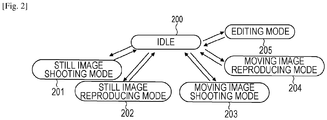
- Fig. 2 is a state (mode) transition diagram according to the present embodiment. Such mode transition is executed in accordance with user operation instructions from the operating unit 162, or by determination by the control unit 161. Accordingly, transition may be performed manually by operations, or transition may take place automatic. As can be seen in Fig. 2 , the imaging apparatus 100 operations by switching through an idle state (200) to the five modes of a still image shooting mode (201), a still image reproducing mode (202), a moving image shooting mode (203), a moving image reproducing mode (204), and an editing mode (205), as appropriate.
- a still image shooting mode a still image reproducing mode
- 203 moving image shooting mode
- 204 moving image reproducing mode
- an editing mode 205
- FIG. 3 illustrates a flowchart relating to shooting processing according to the present embodiment.
- the flowchart in Fig. 3 illustrates processing procedures executed by the control unit 161 controlling each processing block. These processing procedures are realized by loading a program stored in memory (read only memory (ROM)) of the control unit 161 to random access memory (RAM), and the CPU executing the program.
- ROM read only memory
- RAM random access memory
- control unit 161 determines whether or not to stop shooting. If determination is made to stop the shooting processing, transition is made to the idle state, otherwise, the flow advances to S302. An arrangement may be made where the state transitions to the idle state even in the shooting mode, of there is no operating input accepted for a predated amount of time, or there is time till the next shooting.
- the camera control unit 104 controls the operations of the optical unit 101 and imaging sensor unit 102 so that shooting is performed under suitable conditions. For example, lenses included in the optical unit 101 are moved according to zoom or focusing instructions given by the user, a readout region of the imaging sensor unit 102 is set following instructions of the number of shooting pixels, and so forth. Also, control such as focus adjustment and tracking of a particular subject is performed based on evaluation value information and subject information supplied from the later-described evaluation value calculation unit 105 and recognition unit 131. Further, in S302, electric signals obtained by conversion at the imaging sensor unit 102 are subjected to signal processing at the sensor signal processing unit 103 for restoration of pixels.
- the sensor signal processing unit 103 subjects missing or unreliable pixels to interpolation using nearby pixel values for such pixels to be restored, subtracting a predetermined offset value, or the like.
- image information which is output from the sensor signal processing unit 103 after the processing in S302 has ended is called a RAW image, meaning a raw (pre-development) image.
- the RAW reduction unit 109 generates a reduced RAW image from the above-described RAW image.
- the live view developing unit 111 performs developing processing (live view developing) of the reduced RAW image.
- the control unit 161 switches the switch unit 121 within the developing unit 110 to select output of the image information subjected to developing processing by the live view developing unit 111.
- the live view developing unit 111 subject the reduced RAW image to de-Bayering processing (demosaicing processing), i.e., color interpolation processing, so as to convert into signals made up of luminance and color difference (or primary colors).
- de-Bayering processing demosaicing processing
- the signals are then subjected to developing processing such as noise removal, optical distortion correction, image optimization, and so forth.
- the live view developing unit 111 realizes high speed of developing and simple processing, by eliminating or restricting the range of the noise removal and optical distortion correction.
- the developing processing (simple developing) which the live view developing unit 111 performs will be described. Due to the live view developing unit 111 handling reduced RAW images, and restricting part of the developing processing functions, the imaging apparatus 100 can realize shooting with performance such as 60 frames of 2 million pixels per second, for example, using a small circuit scale and low power consumption.
- the image information subjected to developing processing at the live view developing unit 111 is supplied to the evaluation value calculation unit 105.
- the evaluation value calculation unit 105 computes evaluation values such as focus state, exposure state, and so forth, from the luminance values, contrast values, and so forth, included in the image information. Note that the evaluation value calculation unit 105 may obtain a reduced RAW image before live view developing, and calculate some sort of evaluation value from the reduced RAW image as well.
- the image information subjected to developing processing at the live view developing unit 111 is also supplied to the recognition unit 131.
- the recognition unit 131 performs detection of a subject (such as a face) from the image information, and recognizes the subject information. For example, the recognition unit 131 detects whether or not there are faces in the screen of the image information, and if there are faces, recognizes position of the faces and particular people, and outputs the results as information.
- the image information subjected to developing processing at the live view developing unit 111 is also supplied to the display processing unit 122.
- the display processing unit 122 forms a display image from the acquired image information, and outputs to the display unit 123 or an external display device for display.
- a display image on the display unit 123 is used as a live view display for aiding the user in suitably framing the subject, i.e., a live view image for shooting.
- the display image from the display processing unit 122 may be displayed on another external display device such as a television or the like, via the video output terminal 124.
- the display processing unit 122 may use the evaluation value information and subject information output from the evaluation value calculation unit 105 and recognition unit 131 to mark a focused region on the displayed image, displaying a frame at the position where a face has been recognized, and so forth, for example.
- control unit 161 determines whether or not there has been a shooting instruction from the user (a recording instruction in the case of a moving image), and if there has been such an instruction, the flow advances to S310. If there is no instruction in S308, the flow returns to S301, and repeats shooting (recording) preparation operations and live view display.
- the RAW compression unit 113 performs high-efficiency coding (reduced RAW compression) on the reduced RAW image corresponding to the image to be shot (in the case of a moving image, multiple consecutive frames) in response to the aforementioned shooting instruction, and generates a reduced RAW file. Further, in S311, in response to the above-described shooting instructions, the RAW compression unit 113 performs high-efficiency coding (RAW compression) on the RAW image corresponding to the image to be shot (in the case of a moving image, multiple consecutive frames), and generates a RAW file.
- RAW compression high-efficiency coding
- the high-efficiency coding which the RAW compression unit 113 performs here is according to known technology such as wavelet transform, entropy encoding, and so forth, but may be lossy coding or lossless coding.
- a RAW file is generated which can be restored as a high-image-quality file where the quality is the original RAW image is not markedly lost even if the RAW is compressed.
- the reduced RAW file is recorded in the buffer 115. Further, in S313, the RAW file is recorded in the buffer 115. In the case of either file, once the file is recorded in the buffer 115, the timing of recording in a recording medium downstream by the recording/reproducing unit 151 may be either at that point or later. Once the reduced RAW file and the RAW file are recorded to at least the buffer 115, the flow returns to S301.
- the imaging apparatus 100 generates RAW files in response to shooting instructions of still images or moving images (recording instructions) at the time of shooting. Otherwise when shooting, a shooting standby state is effected where an image obtained by live view developing is displayed.
- a RAW file is a high-image-quality file so that the image information supplied from the sensor signal processing unit 103 is not markedly lost, but developing processing is not needed to generate this file. Accordingly, RAW files can be recorded when shooting with a greater number of image pixels and faster consecutive shooting speed, using a small-scale circuit with low electric power consumption.
- FIGs. 4A through 4C illustrate configuration examples of files recorded in the present embodiment, with Fig. 4A illustrating a reduced RAW file, Fig. 4B a RAW file, and Fig. 4C a high-image-quality developed file.
- the reduced RAW file 400 illustrated in Fig. 4A is recorded in a predetermined recording area of the recording medium 152, for example, by the recording/reproducing unit 151.
- the reduced RAW file 400 includes a header portion 401, a metadata portion 402, and a compressed data portion 403.
- the header portion 401 contains identification code indicating that this file is of a reduced RAW file format, and so forth.
- the compressed data portion 403 contains compressed data of a reduced RAW image that has been subjected to high-efficiency coding. In a case of a reduced RAW file of a moving image, compressed audio data is also included.
- the metadata portion 402 includes identification information 404 such as file name of corresponding RAW file, and so forth, generated at the same time as this reduced RAW file.
- this identification information 407 is stored.
- information 405 of the developing status thereof is included.
- shooting metadata 406 including evaluation values and subject information calculated and detected at the evaluation value calculation unit 105 and recognition unit 131 at the time of shooting, and information from the optical unit 101 and imaging sensor unit 102 at the time of shooting (e.g., lens type identification information, sensor type identification information, etc.), is included.
- identification code of a recording medium where a RAW file generated at the same time is recorded, path information of a folder where recorded, a thumbnail of the image, and so forth may further be included.
- the RAW file 410 illustrated in Fig. 4B is recorded in a predetermined recording area of the recording medium 152, for example, by the recording/reproducing unit 151.
- the RAW file 410 includes a header portion 411, a metadata portion 412, and a compressed data portion 413.
- the header portion 411 contains identification code indicating that this file is of a RAW file format, and so forth.
- the compressed data portion 413 contains compressed data of a RAW image that has been subjected to high-efficiency coding. In a case of a RAW file of a moving image, compressed audio data is also included.
- the metadata portion 412 includes identification information 414 such as file name of corresponding reduced RAW file, and so forth, generated at the same time as this RAW file.
- identification information 414 such as file name of corresponding reduced RAW file, and so forth, generated at the same time as this RAW file.
- this identification information 417 is stored.
- information 415 of the developing status thereof in the high-image-quality developing is included.
- shooting metadata 416 including evaluation values and subject information calculated and detected at the evaluation value calculation unit 105 and recognition unit 131 at the time of shooting, and information from the optical unit 101 and imaging sensor unit 102 at the time of shooting (e.g., lens type identification information, sensor type identification information, etc.), is included.
- identification code of a recording medium where a reduced RAW file generated at the same time is recorded may further be included.
- the actual data of the reduced RAW file generated at the same time as this RAW file itself may be made into metadata and sorted in the metadata portion 412.
- the actual data of high-image-quality developed file corresponding to this RAW file may itself be made into metadata and stored in the metadata portion 412.
- the high-image-quality developed file 420 illustrated in Fig. 4C is recorded in a predetermined recording area of the recording medium 152, for example, by the recording/reproducing unit 151.
- the high-image-quality developed file 420 includes a header portion 421, a metadata portion 422, and a compressed data portion 423.
- the header portion 421 contains identification code indicating that this file is of a high-image-quality developed file format, and so forth.
- the compressed data portion 423 contains compressed data of still image portions and moving image portions of a high-image-quality developed file. In a case of a moving image, compressed audio data is also included.
- the metadata portion 422 includes identification information 424 such as the file name of a reduced RAW file corresponding to this high-image-quality developed file, and so forth. Also, identification information 427 of the file name of a RAW file corresponding to the high-image-quality developed file is included. Also, information 425 of the developing status of this high-image-quality developed file in the high-image-quality developing is included. Further, shooting metadata 426 including evaluation values and subject information calculated and detected at the evaluation value calculation unit 105 and recognition unit 131 at the time of shooting, and information from the optical unit 101 and imaging sensor unit 102 at the time of shooting (e.g., lens type identification information, sensor type identification information, etc.), is included. Although omitted from illustration, identification code of a recording medium where the corresponding RAW file and reduced RAW file is recorded, path information of a folder where recorded, a thumbnail of the image, and so forth, may further be included.
- file structures are only exemplary, and may have structures in common with standards such as Design rule for Camera File system (DCF), Exchangeable Image File format (EXIF), Advanced Video Codec High Definition (AVCHD), or Material eXchange Format (MXF).
- DCF Design rule for Camera File system
- EXIF Exchangeable Image File format
- AVCHD Advanced Video Codec High Definition
- MXF Material eXchange Format
- FIG. 5 is a flowchart relating to developing processing according to the present embodiment.
- the flowchart in Fig. 5 illustrates the processing procedures which the control unit 161 carries out by controlling the processing blocks, and is realized by loading a program stored in memory (ROM) of the control unit 161 to memory (RAM), and the CPU executing the program.
- ROM read-only memory
- RAM random access memory
- control unit 161 determines whether or not to perform "catch-up developing" according to user settings when in an idle state (S501), and if determination is made not to perform catch-up developing, the flow ends (returns). If determination is made to perform catch-up developing, the flow advances to S520.
- the "catch-up developing" means that after the shooting operation has ended, a RAW file recorded in the buffer 115 or recording medium 152 is read out, and the RAW image is subjected to high-image-quality developing, thereby generating a high-image-quality developed file.
- This catch-up developing is developing processing performed when the device is idle or in the background of other processing. The name comes from developing processing seeming to chase a RAW file recorded earlier, as if it were trying to catch up. While both still images and moving images may be included in RAW files which are the object of catch-up developing according to the present embodiment, an example of still images will be described below.
- a recorded RAW file is a high-image-quality file where the image information supplied from the sensor signal processing unit 103 is not markedly lost, but reproduction display or printing cannot be performed immediately since the RAW file is data before developing, and a request for reproduction display or printing necessities time for RAW developing.
- a RAW file is not a format in widespread use like JPEG or the like, so reproducing environments which can handle RAW files are restricted. Accordingly, the catch-up developing according to the present embodiment is a useful function.
- catch-up developing Upon catch-up developing being performed in the present embodiment, a RAW file that has already been recorded is read out, subjected to high-image-quality developing processing by the high-image-quality developing unit 112, and the generated high-image-quality developed still image file is recorded in the recording medium 152 or the like.
- This sort of catch-up developing is performed in states where the processing load of the apparatus is relatively low in standby for user operations (when idle), such as in between shootings, when in standby in reproducing mode, in sleep state, or the like.
- the catch-up developing may be initiated manually, but preferably is designed so that the control unit 161 automatically executes in the background in a certain state.
- the control unit 161 determines whether the catch-up developing for the RAW file of interest is already processes or unprocessed. Examples of conceivable ways of determining include whether or not a high-image-quality developed file has been created, from identification information in the RAW file 410, or the like. Alternatively, the developing status information 415 in the RAW file 410 may be referenced to make this determination in the same way. Alternatively again, a table file indicating the state of execution of developing processing of a series of RAW files may be prepared separately and used for determination.
- control unit 161 determines that catch-up developing has been competed for all RAW files of interest, the flow ends (returns) there, and the imaging apparatus 100 transitions to the idle state. If there are any RAW files regarding which the catch-up developing is unprocessed, the flow advances to S521. If a RAW file regarding which catch-up developing is unprocessed has been buffered in the buffer 115 in S521, the flow advances to S523. If not, the RAW file is read out from the recording medium 152 or the like in S522, and temporarily held at the buffer 115.
- the data of the buffer 115 is updated so that the images which are newer in the order of shooting are held with higher priority. That is to say, images shot in the past are deleted from the buffer in order. Thus, the most recently shot images are always held in the buffer, so S522 can be skipped and processing performed at high speed. Further, an arrangement where catch-up developing is performed starting from an image shot immediately prior and going back in time enables images held in the buffer to complete processing with higher priority, so the processing is more efficient.
- the RAW decompression unit 114 decompresses the RAW file read out from the buffer 115 or recording medium 152 and buffered, thereby restoring the RAW image.
- the high-image-quality developing unit 112 executes high-image-quality developing processing on the restored RAW image, and outputs the high-image-quality developed image to the display processing unit 122 and still image compression unit 141 via the switch unit 121. At this time, a display image may be displayed on the display unit 123 if the imaging apparatus 100 is in a state where images developed later can be displayed.
- the high-image-quality developing unit 112 performs de-Bayering processing (demosaicing processing) on the RAW images, i.e., performs color interpolation processing to convert into signals made up of luminance and color difference (or primary color) signals, removes noise included in the signals, corrects optical distortion, and optimizes the image, i.e., performs so-called developing processing.
- the size (number of pixels) of the developed image generated at the high-image-quality developing unit 112 is the full-size read out from the imaging sensor unit 102, or a size set by the user, so the image quality is much higher than the live view developing image that handles around 2 million pixels.
- the high-image-quality developing unit 112 performs each process in higher precision than the live view developing unit 111, so a higher quality developed image is obtained as compared to the live view developing unit 111, but the processing load is greater.
- the high-image-quality developing unit 112 according to the present embodiment has a configuration with increase in circuit scale and electric power consumption suppressed, by avoiding real-time developing processing in parallel with shooting, and enabling developing to be performed taking time.
- the image information subjected to developing processing at the high-image-quality developing unit 112 is supplied to the still image compression unit 141 or the moving image compression unit 142.
- the still image compression unit 141 handles compression.
- the still image compression unit 141 performs high-efficiency coding processing (still image compression) on the acquired high-image-quality developed image, thus generating a high-image-quality developed file (still image file).
- the still image compression unit 141 performs compression processing by a known format such as JPEG or the like.
- the recording/reproducing unit 151 records the high-image-quality developed file in the recording medium 152 or the like.
- control unit 161 determines in S527 that the imaging apparatus 100 is no longer in the idle state, partway through the flow, transition is made to interruption processing. Otherwise, the flow returns to S520. In the processing of S520 and thereafter, if there is a RAW image regarding which catch-up developing is unprocessed, the same processing can be repeatedly executed for each image. On the other hand, in a case of interrupting the catch-up processing in S528, information at the point of the control unit 161 interrupting (RAW file to be interrupted, identification information regarding whether developing completed or not completed, etc.) is stored in memory or the recording medium 152 as recovery information (interruption processing). At the time of performing catch-up developing, the control unit 161 references this recovery information so as to resume from the RAW file that was interrupted. After the interruption processing ends, the imaging apparatus 100 returns to the idle state.
- RAW file to be interrupted, identification information regarding whether developing completed or not completed, etc.
- the high-image-quality developed file recorded in S526 is of a file structure such as illustrated in Fig. 4C .
- the information such as the file name of the original RAW file for this high-image-quality developed file is written to the metadata portion 422.
- Information 425 is also described regarding the fact that this high-image-quality developed file has been subjected to high-image-quality developing by the high-image-quality developing unit 112, and the developing status indicating the content of this developing.
- Shooting metadata 426 including evaluation values and subject information calculated and detected by the evaluation value calculation unit 105 and recognition unit 131, and information at the time of shooting from the optical unit 101 and imaging sensor unit 102, extracted from the metadata of the original RAW file, is also copied. Further, the recording/reproducing unit 151 updates information for each metadata portion of the original RAW file for the catch-up developing, and the reduced RAW file thereof as well, to the newest information relating to the generated high-image-quality developed file.
- the imaging apparatus 100 executes catch-up developing in states where the processing load of the apparatus is relatively low in standby for user operations (when idle), such as in between shootings, when in standby in reproducing mode, in sleep state, or the like.
- High-image-quality developed files are sequentially created from the RAW files.
- FIG. 6 is a flowchart relating to reproducing processing of the present embodiment.
- the flowchart in Fig. 6 illustrates the processing procedures which the control unit 161 carries out by controlling the processing blocks, and is realized by loading a program stored in memory (ROM) of the control unit 161 to memory (RAM), and the CPU executing the program.
- control unit 161 determines whether or not to stop reproduction processing. In a case of stopping reproduction processing, the imaging apparatus 100 returns to the idle state. Otherwise, the flow advances to S602.
- the control unit 161 reads out a reduced RAW image file which is the object of reproduction processing, and determines whether or not to reproduce the reduced RAW image.
- RAW files are high-resolution, and accordingly take time to develop as described above. Further, there is a possibility that a high-image-quality developed file has not net been generated, so when reproducing, the control unit 161 reproduces RAW images with higher priority than others.
- a reduced RAW image has around 2 million pixels, so high-speed processing can be performed in live view developing in the same way, sudden requests for reproducing can be immediately handled, and a reproduced image can be quickly output in quick response. Note however, that a reduced RAW image has limited image quality. While this is effective for general confirmation of the image, it may be insufficient for usages such as confirming details of the image or printing. Accordingly, The imaging apparatus 100 also executes reproduction processing of other images depending on usage, as described below.
- the control unit 161 reproduces the reduced RAW file to be reproduced, from the buffer 115 or recording medium 152 or the like.
- the RAW decompression unit 114 decompresses the compressed reduced RAW image obtained from the reproduced reduced RAW file.
- the high-image-quality developing unit 112 develops the decompressed reduced RAW image to generate a reproduction image, which is supplied to the display processing unit 122. While developing of the reduced RAW image has been described as being performed by the high-image-quality developing unit 112 in S622, this may be performed by the live view developing unit 111 instead.
- the control unit 161 determines whether or not to reproduce a high-image-quality developed image.
- a condition for reproducing a high-image-quality developed image is that the above-described catch-up developing has been performed, or that high-image-quality developing has already been completed by reproduction of the RAW file in response to a user request.
- the control unit 161 reproduces the high-image-quality developed file to be reproduced from the recording medium 152 or the like.
- the still image decompression unit 143 or the moving image decompression unit 144 decompresses the compressed high-image-quality developed image obtained from the reproduced high-image-quality developed file to generate a reproduction image (still image or moving image), which is supplied to the display processing unit 122.
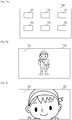
- Figs. 7A, 7B, and 7C are diagrams illustrating examples of display processing of the present embodiment.
- Figs. 7A, 7B, and 7C are examples of image displays at different timings.
- Display example 700 in Fig. 7A is an example of reduced display of six images, denoted by reference numeral 701, on the display unit 123 in a reduced manner.
- This display state is a list display.
- Display example 710 in Fig. 7B is an example of display of one image 711 on the entire display unit 123.
- This display state is a normal display.
- Display example 720 in Fig. 7C is an example of display of an enlarged portion of one image 721 on the entire display unit 123.
- This display state is an enlarged display.
- the enlarged display assumes usage where part of a subject image is displayed in an enlarged manner such as in the display example 720, to confirm details of an image that has been shot, partially extract (trimming), or check whether in focus or not, for example.
- Resolution is sufficient for display of the reproduced image obtained from the reduced RAW image in the state of display examples 700 or 710.
- resolution of a reduced RAW image is insufficient in a case of enlarged display such as in display example 720 (leads to poor resolution), so a RAW file that has high resolution is prefer reproduced and displayed.
- the flow transitions to RAW file reproduction in S604 and thereafter.
- control unit 161 determines whether or not the RAW file to be reproduced has been buffered in the buffer 115. In a case where the RAW file has been buffered, the flow advances to S606, and if not buffered, to S605. In S605, the control unit 161 reads out the RAW file to be reproduced from the recording medium 152 or the like, and buffers in the buffer 115.
- the data of the buffer 115 is updated so that the images which are newer in the order of shooting in the shooting mode are held with higher priority. That is to say, images shot in the past are deleted from the buffer in order. Thus, the most recently shot images are always held in the buffer, so S605 can be skipped and processing performed at high speed.
- the RAW decompression unit 114 obtains the buffered RAW file, and decompresses the compressed RAW image obtained from this RAW file. Further, in S607 the high-image-quality developing unit 112 performs high-image-quality developing of the decompressed RAW image to generate a reproduction image, which is supplied to the display processing unit 122. Note that the imaging apparatus 100 can also newly create a high-image-quality developed file corresponding to the RAW file to be reproduced by the high-image-quality developing in S607.
- the display processing unit 122 outputs one of the reproduction images according to the object of reproduction to the display unit 123 for display.
- the display form is as illustrated in Figs. 7A through 7C .
- the display processing unit 122 can also output the display image from the video output terminal 124 to an external apparatus. Upon the displaying in S608 ending, the flow returns to S601.
- high-image-quality developed files are sequentially created from RAW files in this way.
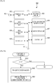
- FIG. 8 is a block diagram illustrating a configuration example of an editing apparatus (external apparatus) that performs editing processing.
- Figs. 9A and 9B are flowcharts relating to editing processing and editing execution of the present embodiment.
- the flowcharts in Figs. 9A and 9B illustrate the processing procedures which the control unit 161 carries out by controlling the processing blocks, and is realized by loading a program stored in memory (ROM) of the control unit 161 to memory (RAM), and the CPU executing the program.
- An editing apparatus 800 in Fig. 8 is an external apparatus from the imaging apparatus 100, more specifically, an external storage or server, or a mobile information terminal (tablet, smartphone, etc.), personal computer (PC), or the like.
- the editing apparatus 800 can exchange various types of files and related information with the imaging apparatus 100.
- a communication unit 802 has a configuration which enables it to access the imaging apparatus 100 via the Internet or by direct communication between apparatuses, by wireless or cabled communication using a communication terminal 801.
- the editing apparatus 800 acquires a reduced RAW file from the external imaging apparatus 100 that is connected over a network via the communication unit 802.
- the received reduced RAW file is saved in a recording medium 803 via an internal bus 811.
- the internal bus 811 is connected with the parts within the editing apparatus 800, and serves as a data bus and system bus.
- the reduced RAW file is decompressed developed, and image information obtained thereby is used in the editing processing.
- a RAW decompression unit 804 reads out a desired reduced RAW file saved in the recording medium 803, and decompresses the compressed reduced RAW image.
- a RAW developing unit 805 performs developing processing of the decompressed reduced RAW image. The image obtained by the developing processing from the reduced RAW image is displayed on a display unit 809.
- a control unit 808 includes a CPU, and unshown memory storing application programs and control programs which the CPU executes.
- the control unit 808 controls the editing processing, which is executed accepting editing instructions from a user monitoring an image displayed on the display unit 809, under control of an editing application program executed by the control unit 808.
- Editing instructions are input from the user by a user interface unit 807.
- the user interface unit 807 uses an operating unit realized by a touch panel, mouse, keyboard, dedicated or general-purpose console, or the like for example, and an editing application that provides display information.
- the displayed reduced RAW image is subjected to trimming, compositing, and so forth, according to editing instructions from the user interface unit 807. If the file is a moving image, instructions that are applied may also include optional scene selection by cut-in/cut-out being specified, effects being applied and so forth.
- An editing information generating unit 806 generates editing information according to the contents of editing.
- the editing information is the contents of editing which the image obtained from the reduced RAW image has been subjected to, in the form of data information.
- the editing information has described therein whether or not editing has been applied to each frame of still images or moving images, and the contents of editing.
- the editing information may further include actual data of the reduced RAW image which has been subjected to the editing processing. This editing information is recorded in the recording medium 803, and also transmitted to the imaging apparatus 100 in response to requests from the imaging apparatus 100.
- Fig. 9A is an editing processing flow
- Fig. 9B is an editing execution flow.
- the control unit 161 determines whether or not to stop editing processing. In a case of stopping editing processing, the imaging apparatus 100 returns to the idle state. In a case of continuing editing processing, the flow advances to S902.
- control unit 161 transmits the reduced RAW file corresponding to the RAW file to be edited, to the editing apparatus 800 which is an external apparatus, as editing data.
- control unit 161 issues an editing command to the editing apparatus 800.
- the editing command is transmitted to the control unit 808, and serves as an editing information generating instruction to the editing apparatus 800. After S903, the flow returns to S901.
- the editing apparatus 800 Upon receiving the aforementioned editing command, the editing apparatus 800 performs the editing processing described above, thereby generating editing information.
- the control unit 161 can start the editing execution flow in Fig. 9B under user instructions, under the condition that generating of the editing information has ended at the editing apparatus 800.
- control unit 161 determines whether or not to stop editing processing. In a case of stopping editing processing, the imaging apparatus 100 returns to the idle state. In a case of continuing editing execution, the flow advances to S912.
- control unit 161 receives from the editing apparatus 800 the editing information corresponding to the RAW file to be edited, using the communication unit 153.
- control unit 161 references this editing information to apply editing or reproduction according to the content described in the received editing information as to the RAW file or reduced RAW file within the imaging apparatus 100. That is to say, the contents of editing on the reduced RAW image performed at the editing apparatus 800 are reproduced on the original RAW image or reduced RAW image within the imaging apparatus 100.
- the flow returns to S911.
- the RAW image subjected to editing execution in this way may be saved as a file where the original file has been updated, or the original image and editing information may each be saved separately and the editing information being reflected when reproducing the image, i.e., edited, each time the image is reproduced.
- the reduced RAW image is used as editing data or as a proxy for the RAW image, whereby the process of editing be streamlined and capabilities increased by this configuration of editing using an external apparatus. Moreover, the overall load on the system regarding editing processing can be reduced.
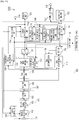
- Fig. 10 is a block diagram illustrating a configuration example of an image processing apparatus according to a second embodiment of the present invention.
- Fig. 10 illustrates an imaging apparatus 1000 as the image processing apparatus according to the present embodiment.
- the imaging apparatus 1000 not only records image information obtained by imaging a subject in a recording medium, but also has functions of reproducing image information from a recording medium, performing developing processing, and displaying, and functions of exchanging image information with an external apparatus, server (cloud), or the like, and performing editing.
- the image processing apparatus according to the present embodiment is not restricted to being expressed as being an imaging apparatus, and may also referred to as being a recording apparatus, reproducing apparatus, recording/reproducing apparatus, communication apparatus, editing apparatus, image processing system, editing system, and so forth.
- Configurations of the imaging apparatus 1000 according to the present embodiment which are the same as those of the imaging apparatus 100 in the first embodiment described above will be denoted with the same reference numerals, and description thereof will be omitted.
- the imaging apparatus 1000 has an imaging module 170 serving as an imaging unit, and an image processing module 180 serving as an image processing unit, the imaging module 170 and the image processing module 180 being connected by a bus 107.
- the RAW data and the like obtained by imaging within the imaging module 170 is supplied to the image processing module 180 via the bus 107.
- the imaging module 170 includes the imaging sensor unit 102, sensor signal processing unit 103, camera control unit 104, and encoding unit 106.
- the image processing module 180 includes a decoding unit 108, RAW reduction unit 109, developing unit 110, live view developing unit 111, high-image-quality developing unit 112, switch unit 121, RAW compression unit 113, RAW decompression unit 114, and buffer 115.
- the image processing module 180 further includes the evaluation value calculation unit 105, recognition unit 131, display processing unit 122, still image compression unit 141, moving image compression unit 142, still image decompression unit 143, moving image decompression unit 144, recording/reproducing unit 151, and control unit 161.
- the imaging apparatus 1000 also has the optical unit 101, display unit 123, video output terminal 124, communication unit 153, communication terminal 154, and built-in or detachable recording medium 152.
- the imaging module 170 internally has the encoding unit 106.
- Examples of encoding processing (compression processing) which can be applied at the encoding unit 106 include compression by Differential Pulse Code Modulation (DPCM) and Golomb coding. This method reduces the amount of information of pixels in pixel data subjected to DPCM processing by Golomb coding of difference values among the pixel data thereof.
- compression may be performed where unnecessary high-band components of the pixel data are deleted using one-dimensional discrete cosine transform (DCT).
- DCT discrete cosine transform
- the rate of compression may be fixed when carrying out either method, or may be designed to be adjustable according to user instructions or the shooting mode.
- Pixel data obtained by the imaging sensor unit 102 converting the subject image when shooting is subjected to pixel restoration processing by the sensor signal processing unit 103.
- This restoration processing involves processing of handling missing or unreliable pixels at the imaging sensor unit 102 by performing interpolation using nearby pixel values for such pixels to be restored, and subtracting a predetermined offset value. This may be altered so that part or all of this restoration processing is not performed here but later when developing.
- the encoding unit 106 performs encoding processing of the pixel data supplied from the sensor signal processing unit 103 according to an aforementioned method.
- the pixel data in the state of having been compressed in the encoding processing is transmitted to the image processing module 180 via the bus 107.
- the compressed pixel data is decoded by the decoding unit 108 disposed at the input portion of the image processing module 180.
- the decoding unit 108 subjects inverse transform from the encoding unit 106 upstream, to decode the compressed pixel data.
- the pixel data that has been compressed by the encoding unit 106 and further decoded by the decoding unit 108 is referred to as a RAW image, meaning a raw (pre-development) image in the present embodiment.
- a RAW image that has been subjected to compression can still be handled as a high-quality RAW image, in the same way as in the first embodiment.
- the RAW image is supplied to the RAW compression unit 113 and compressed again, for efficient recording.
- the RAW image is reduced in size by the RAW reduction unit 109 to effectively perform display and reproduction.
- the RAW reduction unit 109 resizes the input RAW images to HD size (equivalent to around 2 million pixels), for example, thereby generating a reduced RAW image. Processing of the RAW image and reduced RAW image thereafter is the same as in the first embodiment.
- decoding unit 108 and RAW decompression unit 114 in the image processing module 180 which both perform decompression/decoding of compressed RAW images may be realized by a circuit where part or all of the processing circuits of the two are shared or integrated.
- the shooting processing, developing processing, reproduction processing, editing processing, and editing executing processing performed at the imaging apparatus 1000 according to the present embodiment, and the configurations of the files created thereby, are the same as in the first embodiment.
- the same functions as the first embodiment can be realized, while improving the transmission efficiency of RAW data within the imaging apparatus 1000.
- Embodiment(s) of the present invention can also be realized by a computer of a system or apparatus that reads out and executes computer executable instructions (e.g., one or more programs) recorded on a storage medium (which may also be referred to more fully as a 'non-transitory computer-readable storage medium') to perform the functions of one or more of the above-described embodiment(s) and/or that includes one or more circuits (e.g., application specific integrated circuit (ASIC)) for performing the functions of one or more of the above-described embodiment(s), and by a method performed by the computer of the system or apparatus by, for example, reading out and executing the computer executable instructions from the storage medium to perform the functions of one or more of the above-described embodiment(s) and/or controlling the one or more circuits to perform the functions of one or more of the above-described embodiment(s).
- computer executable instructions e.g., one or more programs
- a storage medium which may also be referred to more fully as
- the computer may comprise one or more processors (e.g., central processing unit (CPU), micro processing unit (MPU)) and may include a network of separate computers or separate processors to read out and execute the computer executable instructions.
- the computer executable instructions may be provided to the computer, for example, from a network or the storage medium.
- the storage medium may include, for example, one or more of a hard disk, a random-access memory (RAM), a read only memory (ROM), a storage of distributed computing systems, an optical disk (such as a compact disc (CD), digital versatile disc (DVD), or Blu-ray Disc (BD)TM), a flash memory device, a memory card, and the like.
Landscapes
- Engineering & Computer Science (AREA)
- Multimedia (AREA)
- Signal Processing (AREA)
- Physics & Mathematics (AREA)
- Spectroscopy & Molecular Physics (AREA)
- Television Signal Processing For Recording (AREA)
- Studio Devices (AREA)
Applications Claiming Priority (2)
| Application Number | Priority Date | Filing Date | Title |
|---|---|---|---|
| JP2014186870A JP6406949B2 (ja) | 2014-09-12 | 2014-09-12 | 画像処理装置及び画像処理方法 |
| PCT/JP2015/004171 WO2016038807A1 (en) | 2014-09-12 | 2015-08-20 | Image processing apparatus and image processing method |
Publications (3)
| Publication Number | Publication Date |
|---|---|
| EP3192251A1 EP3192251A1 (en) | 2017-07-19 |
| EP3192251A4 EP3192251A4 (en) | 2018-05-02 |
| EP3192251B1 true EP3192251B1 (en) | 2021-10-06 |
Family
ID=55458582
Family Applications (1)
| Application Number | Title | Priority Date | Filing Date |
|---|---|---|---|
| EP15840630.6A Active EP3192251B1 (en) | 2014-09-12 | 2015-08-20 | Image processing apparatus and image processing method |
Country Status (5)
| Country | Link |
|---|---|
| US (1) | US10003767B2 (zh) |
| EP (1) | EP3192251B1 (zh) |
| JP (1) | JP6406949B2 (zh) |
| CN (1) | CN107079131B (zh) |
| WO (1) | WO2016038807A1 (zh) |
Families Citing this family (6)
| Publication number | Priority date | Publication date | Assignee | Title |
|---|---|---|---|---|
| EP3522527B1 (en) * | 2016-09-29 | 2023-09-06 | Panasonic Intellectual Property Management Co., Ltd. | Reproduction method, creation method, reproduction device, and creation device |
| KR102434417B1 (ko) * | 2017-07-20 | 2022-08-22 | 삼성전자주식회사 | 이미지 데이터 및 이미지 촬영의 제어와 관련된 데이터의 크기에 기반하여, 이미지 데이터 및 이미지 촬영의 제어와 관련된 데이터를 전송하는 방법 및 이를 지원하는 전자 장치 |
| KR102442449B1 (ko) * | 2017-09-01 | 2022-09-14 | 삼성전자주식회사 | 영상 처리 장치, 영상 처리 방법 및 컴퓨터 판독가능 기록 매체 |
| JP7077120B2 (ja) * | 2018-04-26 | 2022-05-30 | キヤノン株式会社 | 情報処理装置およびその制御方法およびプログラム |
| CN112292847B (zh) | 2018-06-25 | 2023-07-28 | 索尼公司 | 图像处理设备、移动设备、方法和存储介质 |
| KR102609734B1 (ko) | 2018-07-20 | 2023-12-05 | 삼성전자 주식회사 | 전자 장치 및 이미지의 전송 상태에 기반하여 이미지를 보정하는 방법 |
Family Cites Families (13)
| Publication number | Priority date | Publication date | Assignee | Title |
|---|---|---|---|---|
| JP4497945B2 (ja) * | 2003-02-04 | 2010-07-07 | キヤノン株式会社 | 撮像装置 |
| JP2006295815A (ja) * | 2005-04-14 | 2006-10-26 | Noritsu Koki Co Ltd | 写真処理装置 |
| JP4908343B2 (ja) * | 2007-08-06 | 2012-04-04 | オリンパス株式会社 | 撮像システム |
| JP4831017B2 (ja) * | 2007-08-27 | 2011-12-07 | ソニー株式会社 | 画像処理装置、現像装置、画像処理方法、現像方法、画像処理プログラム、および現像プログラム |
| JP5495879B2 (ja) * | 2009-04-30 | 2014-05-21 | キヤノン株式会社 | 画像処理システム |
| JP4987129B2 (ja) | 2010-04-23 | 2012-07-25 | キヤノン株式会社 | 画像処理装置及びその制御方法 |
| US9041954B2 (en) * | 2011-06-07 | 2015-05-26 | Hewlett-Packard Development Company, L.P. | Implementing consistent behavior across different resolutions of images |
| US8768142B1 (en) * | 2012-01-26 | 2014-07-01 | Ambarella, Inc. | Video editing with connected high-resolution video camera and video cloud server |
| CN102883167A (zh) * | 2012-09-19 | 2013-01-16 | 旗瀚科技有限公司 | 一种视频图像数据处理方法及系统 |
| JP6108755B2 (ja) * | 2012-10-18 | 2017-04-05 | オリンパス株式会社 | 撮影機器、撮影画像送信方法及び撮影画像送信プログラム |
| JP6012411B2 (ja) * | 2012-11-06 | 2016-10-25 | キヤノン株式会社 | 画像処理装置、画像処理システム、画像処理方法及びプログラム |
| JP6021594B2 (ja) * | 2012-11-08 | 2016-11-09 | オリンパス株式会社 | 撮像装置及びプログラム |
| JP6184080B2 (ja) | 2012-11-20 | 2017-08-23 | ソニー株式会社 | 撮像素子 |
-
2014
- 2014-09-12 JP JP2014186870A patent/JP6406949B2/ja active Active
-
2015
- 2015-08-20 WO PCT/JP2015/004171 patent/WO2016038807A1/en active Application Filing
- 2015-08-20 EP EP15840630.6A patent/EP3192251B1/en active Active
- 2015-08-20 CN CN201580049264.9A patent/CN107079131B/zh active Active
- 2015-08-20 US US15/510,100 patent/US10003767B2/en active Active
Also Published As
| Publication number | Publication date |
|---|---|
| JP6406949B2 (ja) | 2018-10-17 |
| WO2016038807A1 (en) | 2016-03-17 |
| EP3192251A4 (en) | 2018-05-02 |
| US10003767B2 (en) | 2018-06-19 |
| US20170264858A1 (en) | 2017-09-14 |
| CN107079131B (zh) | 2020-03-31 |
| CN107079131A (zh) | 2017-08-18 |
| EP3192251A1 (en) | 2017-07-19 |
| JP2016063251A (ja) | 2016-04-25 |
Similar Documents
| Publication | Publication Date | Title |
|---|---|---|
| EP3192251B1 (en) | Image processing apparatus and image processing method | |
| JP6472253B2 (ja) | 画像処理装置及びその制御方法 | |
| US9918062B2 (en) | Image capturing apparatus, control method of image capturing apparatus, and image processing method | |
| EP3490250B1 (en) | Image processing apparatus and image processing method | |
| EP2974265B1 (en) | Imaging apparatus and imaging apparatus control method | |
| JP5883052B2 (ja) | 画像処理装置及びその制御方法 | |
| EP3192250B1 (en) | Image processing apparatus and image processing method | |
| JP6245819B2 (ja) | 画像処理装置及び画像処理方法 | |
| JP6452362B2 (ja) | 撮像装置及び撮像方法 | |
| JP6245818B2 (ja) | 撮像装置及び撮像装置の制御方法 | |
| JP6192319B2 (ja) | 画像処理装置及び画像処理方法 | |
| JP6327939B2 (ja) | 撮像装置及び撮像装置の制御方法 | |
| JP2016063252A (ja) | 画像処理装置及び画像処理方法 | |
| JP2014179851A (ja) | 撮像装置及び撮像装置の制御方法 | |
| JP2016063254A (ja) | 撮像装置及び撮像方法 |
Legal Events
| Date | Code | Title | Description |
|---|---|---|---|
| STAA | Information on the status of an ep patent application or granted ep patent |
Free format text: STATUS: THE INTERNATIONAL PUBLICATION HAS BEEN MADE |
|
| PUAI | Public reference made under article 153(3) epc to a published international application that has entered the european phase |
Free format text: ORIGINAL CODE: 0009012 |
|
| STAA | Information on the status of an ep patent application or granted ep patent |
Free format text: STATUS: REQUEST FOR EXAMINATION WAS MADE |
|
| 17P | Request for examination filed |
Effective date: 20170412 |
|
| AK | Designated contracting states |
Kind code of ref document: A1 Designated state(s): AL AT BE BG CH CY CZ DE DK EE ES FI FR GB GR HR HU IE IS IT LI LT LU LV MC MK MT NL NO PL PT RO RS SE SI SK SM TR |
|
| AX | Request for extension of the european patent |
Extension state: BA ME |
|
| DAV | Request for validation of the european patent (deleted) | ||
| DAX | Request for extension of the european patent (deleted) | ||
| A4 | Supplementary search report drawn up and despatched |
Effective date: 20180329 |
|
| RIC1 | Information provided on ipc code assigned before grant |
Ipc: H04N 5/232 20060101AFI20180323BHEP Ipc: H04N 5/91 20060101ALI20180323BHEP Ipc: H04N 5/77 20060101ALI20180323BHEP |
|
| REG | Reference to a national code |
Ref country code: DE Ref legal event code: R079 Ref document number: 602015074000 Country of ref document: DE Free format text: PREVIOUS MAIN CLASS: H04N0005910000 Ipc: H04N0005232000 |
|
| GRAP | Despatch of communication of intention to grant a patent |
Free format text: ORIGINAL CODE: EPIDOSNIGR1 |
|
| STAA | Information on the status of an ep patent application or granted ep patent |
Free format text: STATUS: GRANT OF PATENT IS INTENDED |
|
| RIC1 | Information provided on ipc code assigned before grant |
Ipc: H04N 5/232 20060101AFI20210224BHEP Ipc: H04N 9/04 20060101ALI20210224BHEP Ipc: G11B 27/031 20060101ALI20210224BHEP Ipc: H04N 9/804 20060101ALI20210224BHEP Ipc: H04N 9/82 20060101ALI20210224BHEP Ipc: H04N 5/91 20060101ALI20210224BHEP Ipc: H04N 5/77 20060101ALI20210224BHEP |
|
| INTG | Intention to grant announced |
Effective date: 20210329 |
|
| RIN1 | Information on inventor provided before grant (corrected) |
Inventor name: NOZAWA, SHINGO Inventor name: ITO, MASAMICHI |
|
| GRAS | Grant fee paid |
Free format text: ORIGINAL CODE: EPIDOSNIGR3 |
|
| GRAA | (expected) grant |
Free format text: ORIGINAL CODE: 0009210 |
|
| STAA | Information on the status of an ep patent application or granted ep patent |
Free format text: STATUS: THE PATENT HAS BEEN GRANTED |
|
| AK | Designated contracting states |
Kind code of ref document: B1 Designated state(s): AL AT BE BG CH CY CZ DE DK EE ES FI FR GB GR HR HU IE IS IT LI LT LU LV MC MK MT NL NO PL PT RO RS SE SI SK SM TR |
|
| REG | Reference to a national code |
Ref country code: GB Ref legal event code: FG4D |
|
| REG | Reference to a national code |
Ref country code: CH Ref legal event code: EP Ref country code: AT Ref legal event code: REF Ref document number: 1437247 Country of ref document: AT Kind code of ref document: T Effective date: 20211015 |
|
| REG | Reference to a national code |
Ref country code: IE Ref legal event code: FG4D |
|
| REG | Reference to a national code |
Ref country code: DE Ref legal event code: R096 Ref document number: 602015074000 Country of ref document: DE |
|
| REG | Reference to a national code |
Ref country code: LT Ref legal event code: MG9D |
|
| REG | Reference to a national code |
Ref country code: NL Ref legal event code: MP Effective date: 20211006 |
|
| REG | Reference to a national code |
Ref country code: AT Ref legal event code: MK05 Ref document number: 1437247 Country of ref document: AT Kind code of ref document: T Effective date: 20211006 |
|
| PG25 | Lapsed in a contracting state [announced via postgrant information from national office to epo] |
Ref country code: RS Free format text: LAPSE BECAUSE OF FAILURE TO SUBMIT A TRANSLATION OF THE DESCRIPTION OR TO PAY THE FEE WITHIN THE PRESCRIBED TIME-LIMIT Effective date: 20211006 Ref country code: LT Free format text: LAPSE BECAUSE OF FAILURE TO SUBMIT A TRANSLATION OF THE DESCRIPTION OR TO PAY THE FEE WITHIN THE PRESCRIBED TIME-LIMIT Effective date: 20211006 Ref country code: FI Free format text: LAPSE BECAUSE OF FAILURE TO SUBMIT A TRANSLATION OF THE DESCRIPTION OR TO PAY THE FEE WITHIN THE PRESCRIBED TIME-LIMIT Effective date: 20211006 Ref country code: BG Free format text: LAPSE BECAUSE OF FAILURE TO SUBMIT A TRANSLATION OF THE DESCRIPTION OR TO PAY THE FEE WITHIN THE PRESCRIBED TIME-LIMIT Effective date: 20220106 Ref country code: AT Free format text: LAPSE BECAUSE OF FAILURE TO SUBMIT A TRANSLATION OF THE DESCRIPTION OR TO PAY THE FEE WITHIN THE PRESCRIBED TIME-LIMIT Effective date: 20211006 |
|
| PG25 | Lapsed in a contracting state [announced via postgrant information from national office to epo] |
Ref country code: IS Free format text: LAPSE BECAUSE OF FAILURE TO SUBMIT A TRANSLATION OF THE DESCRIPTION OR TO PAY THE FEE WITHIN THE PRESCRIBED TIME-LIMIT Effective date: 20220206 Ref country code: SE Free format text: LAPSE BECAUSE OF FAILURE TO SUBMIT A TRANSLATION OF THE DESCRIPTION OR TO PAY THE FEE WITHIN THE PRESCRIBED TIME-LIMIT Effective date: 20211006 Ref country code: PT Free format text: LAPSE BECAUSE OF FAILURE TO SUBMIT A TRANSLATION OF THE DESCRIPTION OR TO PAY THE FEE WITHIN THE PRESCRIBED TIME-LIMIT Effective date: 20220207 Ref country code: PL Free format text: LAPSE BECAUSE OF FAILURE TO SUBMIT A TRANSLATION OF THE DESCRIPTION OR TO PAY THE FEE WITHIN THE PRESCRIBED TIME-LIMIT Effective date: 20211006 Ref country code: NO Free format text: LAPSE BECAUSE OF FAILURE TO SUBMIT A TRANSLATION OF THE DESCRIPTION OR TO PAY THE FEE WITHIN THE PRESCRIBED TIME-LIMIT Effective date: 20220106 Ref country code: NL Free format text: LAPSE BECAUSE OF FAILURE TO SUBMIT A TRANSLATION OF THE DESCRIPTION OR TO PAY THE FEE WITHIN THE PRESCRIBED TIME-LIMIT Effective date: 20211006 Ref country code: LV Free format text: LAPSE BECAUSE OF FAILURE TO SUBMIT A TRANSLATION OF THE DESCRIPTION OR TO PAY THE FEE WITHIN THE PRESCRIBED TIME-LIMIT Effective date: 20211006 Ref country code: HR Free format text: LAPSE BECAUSE OF FAILURE TO SUBMIT A TRANSLATION OF THE DESCRIPTION OR TO PAY THE FEE WITHIN THE PRESCRIBED TIME-LIMIT Effective date: 20211006 Ref country code: GR Free format text: LAPSE BECAUSE OF FAILURE TO SUBMIT A TRANSLATION OF THE DESCRIPTION OR TO PAY THE FEE WITHIN THE PRESCRIBED TIME-LIMIT Effective date: 20220107 Ref country code: ES Free format text: LAPSE BECAUSE OF FAILURE TO SUBMIT A TRANSLATION OF THE DESCRIPTION OR TO PAY THE FEE WITHIN THE PRESCRIBED TIME-LIMIT Effective date: 20211006 |
|
| REG | Reference to a national code |
Ref country code: DE Ref legal event code: R097 Ref document number: 602015074000 Country of ref document: DE |
|
| PG25 | Lapsed in a contracting state [announced via postgrant information from national office to epo] |
Ref country code: SM Free format text: LAPSE BECAUSE OF FAILURE TO SUBMIT A TRANSLATION OF THE DESCRIPTION OR TO PAY THE FEE WITHIN THE PRESCRIBED TIME-LIMIT Effective date: 20211006 Ref country code: SK Free format text: LAPSE BECAUSE OF FAILURE TO SUBMIT A TRANSLATION OF THE DESCRIPTION OR TO PAY THE FEE WITHIN THE PRESCRIBED TIME-LIMIT Effective date: 20211006 Ref country code: RO Free format text: LAPSE BECAUSE OF FAILURE TO SUBMIT A TRANSLATION OF THE DESCRIPTION OR TO PAY THE FEE WITHIN THE PRESCRIBED TIME-LIMIT Effective date: 20211006 Ref country code: EE Free format text: LAPSE BECAUSE OF FAILURE TO SUBMIT A TRANSLATION OF THE DESCRIPTION OR TO PAY THE FEE WITHIN THE PRESCRIBED TIME-LIMIT Effective date: 20211006 Ref country code: DK Free format text: LAPSE BECAUSE OF FAILURE TO SUBMIT A TRANSLATION OF THE DESCRIPTION OR TO PAY THE FEE WITHIN THE PRESCRIBED TIME-LIMIT Effective date: 20211006 Ref country code: CZ Free format text: LAPSE BECAUSE OF FAILURE TO SUBMIT A TRANSLATION OF THE DESCRIPTION OR TO PAY THE FEE WITHIN THE PRESCRIBED TIME-LIMIT Effective date: 20211006 |
|
| PLBE | No opposition filed within time limit |
Free format text: ORIGINAL CODE: 0009261 |
|
| STAA | Information on the status of an ep patent application or granted ep patent |
Free format text: STATUS: NO OPPOSITION FILED WITHIN TIME LIMIT |
|
| 26N | No opposition filed |
Effective date: 20220707 |
|
| PG25 | Lapsed in a contracting state [announced via postgrant information from national office to epo] |
Ref country code: AL Free format text: LAPSE BECAUSE OF FAILURE TO SUBMIT A TRANSLATION OF THE DESCRIPTION OR TO PAY THE FEE WITHIN THE PRESCRIBED TIME-LIMIT Effective date: 20211006 |
|
| REG | Reference to a national code |
Ref country code: DE Ref legal event code: R079 Ref document number: 602015074000 Country of ref document: DE Free format text: PREVIOUS MAIN CLASS: H04N0005232000 Ipc: H04N0023600000 |
|
| PG25 | Lapsed in a contracting state [announced via postgrant information from national office to epo] |
Ref country code: SI Free format text: LAPSE BECAUSE OF FAILURE TO SUBMIT A TRANSLATION OF THE DESCRIPTION OR TO PAY THE FEE WITHIN THE PRESCRIBED TIME-LIMIT Effective date: 20211006 |
|
| REG | Reference to a national code |
Ref country code: DE Ref legal event code: R119 Ref document number: 602015074000 Country of ref document: DE |
|
| PG25 | Lapsed in a contracting state [announced via postgrant information from national office to epo] |
Ref country code: MC Free format text: LAPSE BECAUSE OF FAILURE TO SUBMIT A TRANSLATION OF THE DESCRIPTION OR TO PAY THE FEE WITHIN THE PRESCRIBED TIME-LIMIT Effective date: 20211006 |
|
| REG | Reference to a national code |
Ref country code: CH Ref legal event code: PL |
|
| PG25 | Lapsed in a contracting state [announced via postgrant information from national office to epo] |
Ref country code: LU Free format text: LAPSE BECAUSE OF NON-PAYMENT OF DUE FEES Effective date: 20220820 Ref country code: LI Free format text: LAPSE BECAUSE OF NON-PAYMENT OF DUE FEES Effective date: 20220831 Ref country code: CH Free format text: LAPSE BECAUSE OF NON-PAYMENT OF DUE FEES Effective date: 20220831 |
|
| REG | Reference to a national code |
Ref country code: BE Ref legal event code: MM Effective date: 20220831 |
|
| PG25 | Lapsed in a contracting state [announced via postgrant information from national office to epo] |
Ref country code: IT Free format text: LAPSE BECAUSE OF FAILURE TO SUBMIT A TRANSLATION OF THE DESCRIPTION OR TO PAY THE FEE WITHIN THE PRESCRIBED TIME-LIMIT Effective date: 20211006 |
|
| PG25 | Lapsed in a contracting state [announced via postgrant information from national office to epo] |
Ref country code: IE Free format text: LAPSE BECAUSE OF NON-PAYMENT OF DUE FEES Effective date: 20220820 Ref country code: FR Free format text: LAPSE BECAUSE OF NON-PAYMENT OF DUE FEES Effective date: 20220831 Ref country code: DE Free format text: LAPSE BECAUSE OF NON-PAYMENT OF DUE FEES Effective date: 20230301 |
|
| PG25 | Lapsed in a contracting state [announced via postgrant information from national office to epo] |
Ref country code: BE Free format text: LAPSE BECAUSE OF NON-PAYMENT OF DUE FEES Effective date: 20220831 |
|
| PGFP | Annual fee paid to national office [announced via postgrant information from national office to epo] |
Ref country code: GB Payment date: 20230720 Year of fee payment: 9 |
|
| PG25 | Lapsed in a contracting state [announced via postgrant information from national office to epo] |
Ref country code: HU Free format text: LAPSE BECAUSE OF FAILURE TO SUBMIT A TRANSLATION OF THE DESCRIPTION OR TO PAY THE FEE WITHIN THE PRESCRIBED TIME-LIMIT; INVALID AB INITIO Effective date: 20150820 |
|
| PG25 | Lapsed in a contracting state [announced via postgrant information from national office to epo] |
Ref country code: CY Free format text: LAPSE BECAUSE OF FAILURE TO SUBMIT A TRANSLATION OF THE DESCRIPTION OR TO PAY THE FEE WITHIN THE PRESCRIBED TIME-LIMIT Effective date: 20211006 |