EP3190645A1 - Electrode plate coating removal apparatus - Google Patents
Electrode plate coating removal apparatus Download PDFInfo
- Publication number
- EP3190645A1 EP3190645A1 EP14901535.6A EP14901535A EP3190645A1 EP 3190645 A1 EP3190645 A1 EP 3190645A1 EP 14901535 A EP14901535 A EP 14901535A EP 3190645 A1 EP3190645 A1 EP 3190645A1
- Authority
- EP
- European Patent Office
- Prior art keywords
- coating layer
- electrode plate
- laser
- region
- laser beam
- Prior art date
- Legal status (The legal status is an assumption and is not a legal conclusion. Google has not performed a legal analysis and makes no representation as to the accuracy of the status listed.)
- Withdrawn
Links
Images



Classifications
-
- H—ELECTRICITY
- H01—ELECTRIC ELEMENTS
- H01M—PROCESSES OR MEANS, e.g. BATTERIES, FOR THE DIRECT CONVERSION OF CHEMICAL ENERGY INTO ELECTRICAL ENERGY
- H01M4/00—Electrodes
- H01M4/02—Electrodes composed of, or comprising, active material
- H01M4/04—Processes of manufacture in general
- H01M4/0471—Processes of manufacture in general involving thermal treatment, e.g. firing, sintering, backing particulate active material, thermal decomposition, pyrolysis
-
- H—ELECTRICITY
- H01—ELECTRIC ELEMENTS
- H01M—PROCESSES OR MEANS, e.g. BATTERIES, FOR THE DIRECT CONVERSION OF CHEMICAL ENERGY INTO ELECTRICAL ENERGY
- H01M4/00—Electrodes
- H01M4/02—Electrodes composed of, or comprising, active material
- H01M4/64—Carriers or collectors
-
- B—PERFORMING OPERATIONS; TRANSPORTING
- B23—MACHINE TOOLS; METAL-WORKING NOT OTHERWISE PROVIDED FOR
- B23K—SOLDERING OR UNSOLDERING; WELDING; CLADDING OR PLATING BY SOLDERING OR WELDING; CUTTING BY APPLYING HEAT LOCALLY, e.g. FLAME CUTTING; WORKING BY LASER BEAM
- B23K26/00—Working by laser beam, e.g. welding, cutting or boring
- B23K26/352—Working by laser beam, e.g. welding, cutting or boring for surface treatment
-
- H—ELECTRICITY
- H01—ELECTRIC ELEMENTS
- H01M—PROCESSES OR MEANS, e.g. BATTERIES, FOR THE DIRECT CONVERSION OF CHEMICAL ENERGY INTO ELECTRICAL ENERGY
- H01M10/00—Secondary cells; Manufacture thereof
- H01M10/05—Accumulators with non-aqueous electrolyte
- H01M10/052—Li-accumulators
- H01M10/0525—Rocking-chair batteries, i.e. batteries with lithium insertion or intercalation in both electrodes; Lithium-ion batteries
-
- H—ELECTRICITY
- H01—ELECTRIC ELEMENTS
- H01M—PROCESSES OR MEANS, e.g. BATTERIES, FOR THE DIRECT CONVERSION OF CHEMICAL ENERGY INTO ELECTRICAL ENERGY
- H01M4/00—Electrodes
- H01M4/02—Electrodes composed of, or comprising, active material
- H01M4/04—Processes of manufacture in general
-
- H—ELECTRICITY
- H01—ELECTRIC ELEMENTS
- H01M—PROCESSES OR MEANS, e.g. BATTERIES, FOR THE DIRECT CONVERSION OF CHEMICAL ENERGY INTO ELECTRICAL ENERGY
- H01M2220/00—Batteries for particular applications
- H01M2220/20—Batteries in motive systems, e.g. vehicle, ship, plane
-
- H—ELECTRICITY
- H01—ELECTRIC ELEMENTS
- H01M—PROCESSES OR MEANS, e.g. BATTERIES, FOR THE DIRECT CONVERSION OF CHEMICAL ENERGY INTO ELECTRICAL ENERGY
- H01M2220/00—Batteries for particular applications
- H01M2220/30—Batteries in portable systems, e.g. mobile phone, laptop
-
- H—ELECTRICITY
- H01—ELECTRIC ELEMENTS
- H01M—PROCESSES OR MEANS, e.g. BATTERIES, FOR THE DIRECT CONVERSION OF CHEMICAL ENERGY INTO ELECTRICAL ENERGY
- H01M4/00—Electrodes
- H01M4/02—Electrodes composed of, or comprising, active material
- H01M4/64—Carriers or collectors
- H01M4/66—Selection of materials
- H01M4/661—Metal or alloys, e.g. alloy coatings
-
- H—ELECTRICITY
- H01—ELECTRIC ELEMENTS
- H01M—PROCESSES OR MEANS, e.g. BATTERIES, FOR THE DIRECT CONVERSION OF CHEMICAL ENERGY INTO ELECTRICAL ENERGY
- H01M50/00—Constructional details or processes of manufacture of the non-active parts of electrochemical cells other than fuel cells, e.g. hybrid cells
- H01M50/50—Current conducting connections for cells or batteries
- H01M50/531—Electrode connections inside a battery casing
- H01M50/536—Electrode connections inside a battery casing characterised by the method of fixing the leads to the electrodes, e.g. by welding
-
- Y—GENERAL TAGGING OF NEW TECHNOLOGICAL DEVELOPMENTS; GENERAL TAGGING OF CROSS-SECTIONAL TECHNOLOGIES SPANNING OVER SEVERAL SECTIONS OF THE IPC; TECHNICAL SUBJECTS COVERED BY FORMER USPC CROSS-REFERENCE ART COLLECTIONS [XRACs] AND DIGESTS
- Y02—TECHNOLOGIES OR APPLICATIONS FOR MITIGATION OR ADAPTATION AGAINST CLIMATE CHANGE
- Y02E—REDUCTION OF GREENHOUSE GAS [GHG] EMISSIONS, RELATED TO ENERGY GENERATION, TRANSMISSION OR DISTRIBUTION
- Y02E60/00—Enabling technologies; Technologies with a potential or indirect contribution to GHG emissions mitigation
- Y02E60/10—Energy storage using batteries
-
- Y—GENERAL TAGGING OF NEW TECHNOLOGICAL DEVELOPMENTS; GENERAL TAGGING OF CROSS-SECTIONAL TECHNOLOGIES SPANNING OVER SEVERAL SECTIONS OF THE IPC; TECHNICAL SUBJECTS COVERED BY FORMER USPC CROSS-REFERENCE ART COLLECTIONS [XRACs] AND DIGESTS
- Y02—TECHNOLOGIES OR APPLICATIONS FOR MITIGATION OR ADAPTATION AGAINST CLIMATE CHANGE
- Y02P—CLIMATE CHANGE MITIGATION TECHNOLOGIES IN THE PRODUCTION OR PROCESSING OF GOODS
- Y02P70/00—Climate change mitigation technologies in the production process for final industrial or consumer products
- Y02P70/50—Manufacturing or production processes characterised by the final manufactured product
Definitions
- the present invention relates to a field of energy storage device, and particularly relates to a device for removing a coating layer of an electrode plate.
- Lithium-ion battery has been widely concerned due to its advantages, such as high energy density, environment-friendly and the like, and has been widely applied in electronic devices, such as a mobile phone, a laptop and the like, and with technical development of electric vehicle, application of the lithium-ion battery in the field of electric vehicle is becoming more and more concerned.
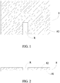
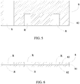
- a coating layer 82 of an electrode plate 8 is continuous due to coating, or an electrode tab needs to be soldered to the middle portion of the electrode plate, in order to realize that an electrode tab is welded onto the electrode plate 8, firstly the coating layer 82 of the electrode plate 8 within a region where the electrode tab will be welded (or this region is referred to as a region R where the coating layer will be removed) needs to be removed. And, in some special process of manufacturing the battery, it further requires to remove coating layers 82 in different shapes at different positions of the electrode plate 8 of the battery. For example, as shown in FIG. 3, FIG.4 , FIG.5 and FIG.6 , it sometimes further requires to remove the coating layer 82 within the region R where the coating layer will be removed at corresponding positions of the two surfaces of the electrode plate 8.
- the principle of laser removing is: under the action of laser, the coating layer adsorbs a certain energy, particles of the coating layer are gasified, sublimed and vibrated and the like, so that the coating layer is removed. Because an energy distribution of a laser beam emitted from a laser device generally is Gaussian distribution, the laser beam has high energy in the middle and low energy at an edge under such a distribution.
- a certain range of energy is required to remove the coating layer 82 of the electrode plate 8, so in such a laser beam whose energy is distributed as Gaussian distribution, relative high energy in the middle easily damages a foil (because a current collector 81 of the electrode plate 8 of the battery generally is a Cu foil and an A1 foil, a thickness of the current collector 81 is several microns to ten microns, such a high energy part quite easily penetrates A1 foil or Cu foil), thereby affecting removing quality and welding quality of the electrode tab; but energy at the edge is lower than the energy required on removing, so the coating layer remains at a position corresponding to the energy at the edge, thereby also affecting the removing quality.
- these high energy and low energy make energy utilization rate quite low because they cannot be effectively utilized.
- the coating layer 82 of the electrode plate 8 is removed by laser, under the action of laser, the coating layer 82 is heated, stress in the coating layer 82 will be changed, which in turn results in deformation of the electrode plate 8; after the coating layer 82 is removed, because residual stress is released, the electrode plate 8 will also generate a slight deformation, which in turn affects later welding of the electrode tab.
- an inert gas is blown toward the region of the electrode plate 8 where the coating layer has been removed, so as to realize cleaning and cooling of the electrode plate 8.
- particles within the region where the coating layer has been removed cannot be completely got rid of by such a manner, so that the particles will remain around the region where the coating layer has been removed, and affect property of the battery.
- the laser will ceaselessly accelerate and decelerate at a corner of the region where the coating will be removed, which thus results in removing quality unstable upon moving of a laser head, a removing size not precise, so such a manner is hard to realize mass production.
- an object of the present invention is to provide a device for removing a coating layer of an electrode plate, which can avoid damage to the electrode plate.
- Another object of the present invention is to provide a device for removing a coating layer of an electrode plate, which can avoid the deformation of the electrode plate.
- Another object of the present invention is to provide a device for removing a coating layer of an electrode plate, which can promote the energy utilization rate, the removing quality and the removing efficiency of the laser.
- the present invention provides a device for removing a coating layer of an electrode plate, an electrode plate comprises a current collector and a coating layer coated on each of at least one surface of the current collector, the device for removing the coating layer of the electrode plate comprises: a conveying system for conveying the electrode plate which has the coating layer to be removed; at least one wetting mechanism, each wetting mechanism is provided at the coating layer to be removed on one surface of the electrode plate which is conveyed by the conveying system and wets the coating layer on the one surface of the electrode plate within the region where the coating layer will be removed by using a solvent; a laser removing system; and a control system communicating with the conveying system, the at least one wetting mechanism and the laser removing system.
- the laser removing system comprises: at least one laser emitting head for emitting a laser beam and projecting the laser beam onto the coating layer on the corresponding surface of the electrode plate within the region where the coating layer will be removed and which is wetted by the wetting mechanism to make the solvent which wets the coating layer of the electrode plate within the region where the coating layer will be removed vaporized, so as to remove the coating layer on the surface of the electrode plate within the region where the coating layer will be removed and in turn expose the current collector on the surface of the electrode plate corresponding to the region where the coating layer will be removed.
- the wetting mechanism is provided and the coating layer of the electrode plate within the region where the coating layer will be removed is wetted in advance by using the solvent, after the laser removing system emits the laser beam on the wetted electrode plate, the solvent existing in the electrode plate can directly or indirectly absorb the energy of the laser beam so as to be instantaneously vaporized, or the particles of the coating layer absorb the energy of the laser beam, so that the temperature at the interface between the particles of the coating layer and the solvent instantaneously increases via interface heat transfer and the temperature at the interface is far more above the vaporization (evaporation) temperature of the solvent, an explosive evaporation of the solvent occurs, thereby generating a strong transient pressure, the particles of the coating layer are peeled off from the current collector under the action of the strong pressure, so as to remove the particles of the coating layer.
- the transient pressure will not damage the electrode plate, and the energy of the laser beam is directly or indirectly absorbed by the solvent, the current collector of the electrode plate will not be damaged, meanwhile, the coating layer is removed from the electrode plate under the action of the pressure generated by the instantaneous vaporization of the solvent, the residual stress after the coating layer is removed is small, thereby avoiding the deformation of the electrode plate; furthermore, the energy utilization rate of the laser, the removing quality and the removing efficiency can be promoted.
- an electrode plate 8 comprises a current collector 81 and a coating layer 82 coated on each of at least one surface of the current collector 81
- the device for removing the coating layer of the electrode plate comprises: a conveying system 1 for conveying the electrode plate 8 which has the coating layer 82 to be removed; at least one wetting mechanism 2, each wetting mechanism 2 is provided at the coating layer 82 to be removed on one surface of the electrode plate 8 which is conveyed by the conveying system 1 and wets the coating layer 82 on the one surface of the electrode plate 8 within the region R where the coating layer will be removed by using a solvent; a laser removing system 3; and a control system 4 communicating with the conveying system 1, the at least one wetting mechanism 2 and the laser removing system 3.
- the laser removing system 3 comprises: at least one laser emitting head 31 for emitting a laser beam and projecting the laser beam onto the coating layer 82 on the corresponding surface of the electrode plate 8 within the region R where the coating layer will be removed and which is wetted by the wetting mechanism 2 to make the solvent which wets the coating layer 82 of the electrode plate 8 within the region R where the coating layer will be removed vaporized, so as to remove the coating layer 82 on the surface of the electrode plate 8 within the region R where the coating layer will be removed and in turn expose the current collector 81 on the surface of the electrode plate 8 corresponding to the region R where the coating layer will be removed.
- the wetting mechanism 2 is provided and the coating layer 82 of the electrode plate 8 within the region R where the coating layer will be removed is wetted in advance by using the solvent, after the laser removing system 3 emits the laser beam on the wetted electrode plate 8, the solvent existing in the electrode plate 8 can directly or indirectly absorb the energy of the laser beam so as to be instantaneously vaporized, or the particles of the coating layer 82 absorb the energy of the laser beam, so that the temperature at the interface between the particles of the coating layer 82 and the solvent instantaneously increases via interface heat transfer and the temperature at the interface is far more above the vaporization (evaporation) temperature of the solvent, an explosive evaporation of the solvent occurs, thereby generating a strong transient pressure, the particles of the coating layer 82 are peeled off from the current collector 81 under the action of the strong pressure, so as to remove the particles of the coating layer 82.
- the transient pressure will not damage the electrode plate 8, and the energy of the laser beam is directly or indirectly absorbed by the solvent, the current collector 81 of the electrode plate 8 will not be damaged, meanwhile, the coating layer 82 is removed from the electrode plate 8 under the action of the pressure generated by the instantaneous vaporization of the solvent, the residual stress after the coating layer 82 is removed is small, thereby avoiding the deformation of the electrode plate 8; furthermore, the energy of the laser beam can be directly or indirectly absorbed by the solvent, thereby promoting the energy utilization rate of the laser; after the solvent directly or indirectly absorbs the energy of the laser, an explosive evaporation of the solvent occurs, thereby promoting the removing quality and the removing efficiency.
- the exposed current collector 81 corresponding to the region where the coating layer 82 has been removed may be used to weld an electrode tab.
- the electrode plate may be an electrode plate of a super capacitor, or an electrode plate of a lithium ion battery, the coating layer may be a positive material layer or a negative material layer).
- the conveying system 1 may comprise: an unwinding roller 11 provided at an upstream position of the laser removing system 3 for providing and feeding the electrode plate 8 which has the coating layer 82 to be removed; a winding roller 12 provided at a downstream position of the laser removing system 3 for winding the electrode plate 8 where the coating layer 82 has been removed; and a plurality of fixing rollers 13 provided between the unwinding roller 11 and the winding roller 12 for guiding and conveying the electrode plate 8.
- the conveying system 1 may further comprise: a deviation rectifying mechanism 14 provided at a downstream position of the unwinding roller 11 for positioning a conveying position of the electrode plate 8 which has the coating layer 82 to be removed.
- the laser removing system 3 may further comprise: a sensor 32 provided at an upstream position of the wetting mechanism 2 for positioning the region R where the coating layer will be removed of the coating layer 82 on a corresponding surface of the electrode plate 8.
- the laser removing system 3 may further comprise: an adsorption fixing mechanism 33 provided at a surface opposite to one surface of the electrode plate 8 on which the laser removing system 3 emits the laser beam and which has the coating layer 82 to be removed, for fixing the region R where the coating layer will be removed of the coating layer 82 on the corresponding one surface of the electrode plate 8. Because the region R where the coating layer will be removed of the coating layer 82 on the corresponding one surface of the electrode plate 8 is fixed by the adsorption fixing mechanism 33, the deformation of the electrode plate 8 during the laser removing process is restrained.
- the laser removing system 3 may further comprise: a cooling mechanism 34 provided at a surface opposite to the one surface of the electrode plate 8 on which the laser removing system 3 emits the laser beam and which has the coating layer 82 to be removed, for absorbing the energy generated during the laser beam emitting process. Therefore, the deformation of the electrode plate 8 caused by heating the electrode plate 8 during the laser removing process may be avoided.
- the adsorption fixing mechanism 33 and the cooling mechanism 34 may be integrally formed, the adsorption fixing mechanism 33 may be a vacuum platform, the cooling mechanism 34 may be a cooling pipeline provided in the vacuum platform.
- the device for removing the coating layer of the electrode plate may further comprise: two dust collecting mechanisms 5 provided between the electrode plate 8 and the laser removing system 3, and provided at two sides of the coating layer 82 within the region R where the coating layer will be removed corresponding to the one surface of the electrode plate 8, so as to remove the particles of the coating layer 82 generated during the laser removing process.
- the dust collecting mechanism 5 may be a downdraught dust collecting mechanism having a certain negative pressure.
- the generated particles enter into a particle discharging pipeline (not shown) of the dust collecting mechanism 5, which thus may ensure the particles not to remain on the electrode plate 8, prevent the particles from affecting the property of a product (for example, a super capacitor or a lithium ion battery) using the electrode plate 8, at the same time may further prevent the particles from polluting the environment.
- a product for example, a super capacitor or a lithium ion battery
- the laser removing system 3 may further comprise: a beam shaping mechanism 35 provided between the laser emitting head 31 and the electrode plate 8, electrically connected to the laser emitting head 31 for homogenizing the energy of the laser beam emitted from the laser emitting head 31.
- the beam shaping mechanism 35 can homogenize the energy of the laser beam without damaging the current collector 81 of the electrode plate 8, thereby promoting the welding quality of tabs; also, the beam shaping mechanism 35 will not result in a residue of the coating layer 82, thereby promoting the removing quality, and the high energy and the low energy in the laser beam can be efficiently used, so that the energy of the laser beam can be used to maximum extent so as to promote the energy utilization rate, increase the removing efficiency and the removing quality.
- the beam shaping mechanism 35 may further convert a spot to a laser beam having a different size and a different shape, for example a rectangle, a square, a circle, an ellipse, a trapezoid and the like. When the energy is constant, depending on difficulty of removing dirt or particles, an outputted laser beam may have a different energy density simply by adjusting an area of the spot, so that the outputted laser beam has great removing capability.
- the laser removing system 3 may further comprise: a galvanometer scanning mechanism 36 provided between the beam shaping mechanism 35 and the electrode plate 8, electrically connected to the beam shaping mechanism 35.
- the galvanometer scanning mechanism 36 brings the following advantages: the galvanometer scanning mechanism 36 has relative high flexibility in removing pattern, can reach a high scanning speed, allows speed to be stable, has relative high resolution ratio with respect to movement, can allow positioning to be more precisely, can perform fine removing, promote precision in removing size and stability, promote removing quality.
- the galvanometer scanning mechanism 36 can rapidly and accurately realize to position the movement of the laser beam, which can promote the region where the coating layer has been removed in size precision, positioning precision, removing quality and stability, but a laser system with a fixing laser emitting head cannot attain such a speed and precision. Therefore, the present invention can be applied for mass production in industry with high quality and high speed.
- the laser removing system 3 may further comprise: a focusing lens 37 provided between the galvanometer scanning mechanism 36 and the electrode plate 8.
- the wetting mechanism 2 may be provided as one in number, the one wetting mechanism 2 is correspondingly provided at the one surface of the electrode plate 8 which is conveyed by the conveying system 1 and has the coating layer 82 to be removed; and the laser emitting head 31 may be provided as one in number, the one laser emitting head 31 is correspondingly provided at a downstream position of the one wetting mechanism 2, emits the laser beam and projects the laser beam on the coating layer 82 on the corresponding one surface of the electrode plate 8 within the region R where the coating layer will be removed and which is wetted by the wetting mechanism 2.
- the present embodiment may be used to perform the coating layer removing operation at only one surface of the electrode plate 8, the result of the electrode plate 8 with the coating layer removed is illustrated in FIG. 1 and FIG. 2 .
- the present embodiment may be also used to perform the coating layer removing operation respectively on the two opposite surfaces of the electrode plate 8, the result of the electrode plate 8 with the coating layers removed is illustrated in FIG. 3, FIG. 4 , FIG. 5 and FIG. 6 , however, the previous coating layer removing operation will be performed twice.
- the wetting mechanism 2 may be provided as two in number, the two wetting mechanisms 2 are respectively provided at the two opposite surfaces of the electrode plate 8 which is conveyed by the conveying system 1 and has the coating layer 82 to be removed; and the laser emitting head 31 may be provided as two in number, the two laser emitting heads 31 each are provided at a corresponding downstream position of one corresponding wetting mechanism 2, one laser emitting head 31 emits a laser beam and projects the laser beam on the corresponding coating layer 82 on one surface of the electrode plate 8 within the region R where the coating layer will be removed and which is wetted by one wetting mechanism 2, the other laser emitting head 31 emits a laser beam and projects the laser beam on the corresponding coating layer 82 on the other surface of the electrode plate 8 within the region R where the coating layer will be removed and which is wetted by the other wetting mechanism 2.
- the present embodiment may be used to perform the coating layer removing operation on the two opposite surfaces of the electrode plate 8, the result of the electrode plate 8 with the coating layers removed is illustrated in FIG. 3, FIG. 4 , FIG. 5 and FIG. 6 , and the coating layer removing operation will be performed only once.
- the wetting mechanism 2 may be provided as two in number, the two wetting mechanisms 2 are respectively provided at the two opposite surfaces of the electrode plate 8 which is conveyed by the conveying system 1 and has the coating layer 82 to be removed; and the laser emitting head 31 may be provided as one in number; the laser removing system 3 may further comprise: at least one beam path switching mechanism 38 provided between the laser emitting head 31 and the electrode plate 8 for changing a transmission direction of the laser beam, so that the laser beam emitted from the laser emitting head 31 can be projected sequentially or simultaneously on one corresponding coating layer 82 on one surface of the electrode plate 8 within the region R where the coating layer will be removed and which is wetted by one corresponding wetting mechanism 2 and the other coating layer 82 on the other surface of the electrode plate 8 within the region R where the coating layer will be removed and which is wetted by the other wetting mechanism 2.
- the present embodiment may be used to perform the coating layer removing operation on the two opposite surfaces of the electrode plate 8, the result of the electrode plate 8 with the coating layers removed is illustrated in FIG. 3, FIG. 4 , FIG. 5 and FIG. 6 , and the coating layer removing operation will be performed only once.
- the conveying system 1 may further comprise: a plurality of guiding rollers 15 for guiding and conveying the electrode plate 8 so as to make the two opposite surfaces of the electrode plate 8 upside down, and make the electrode plate 8 upside down pass through the laser removing system 3; and a plurality of buffering rollers 16 provided between the two wetting mechanisms 2 so as to make the conveyance of the electrode plate 8 slowly transited when the coating layer removing operation is performed on the two opposite surfaces of the electrode plate 8.
- the plurality of guiding rollers 15 may further be provided to make the electrode plate 8 which has been upside down and has passed though the laser removing system 3 upside down again, so as to convey the electrode plate 8 to the winding roller 12.
- the device for removing the coating layer of the electrode plate may further comprise: a dust sticking mechanism 6 provided at a downstream position of the laser removing system 3, communicating with the control system 4 for removing the particles and impurities of the residue on the electrode plate 8 after the coating layer 82 is removed.
- the dust sticking mechanism 6 may be a dust sticking roller.
- the device for removing the coating layer of the electrode plate may further comprise: a quality monitoring system 7 provided at a downstream position of the laser removing system 3, communicating with the control system 4 for monitoring the removing quality of the coating layer 82 on the electrode plate 8 and feedbacking the monitoring information to the control system 4. If the removing effect is unsatisfactory, it may perform a next coating layer removing operation as the above or perform manual removing.
- the communication may be a wired communication or a wireless communication.
Landscapes
- Chemical & Material Sciences (AREA)
- Engineering & Computer Science (AREA)
- Chemical Kinetics & Catalysis (AREA)
- Electrochemistry (AREA)
- General Chemical & Material Sciences (AREA)
- Manufacturing & Machinery (AREA)
- Materials Engineering (AREA)
- Physics & Mathematics (AREA)
- Plasma & Fusion (AREA)
- Mechanical Engineering (AREA)
- Optics & Photonics (AREA)
- Battery Electrode And Active Subsutance (AREA)
- Laser Beam Processing (AREA)
- Application Of Or Painting With Fluid Materials (AREA)
- Fixed Capacitors And Capacitor Manufacturing Machines (AREA)
Abstract
Description
- The present invention relates to a field of energy storage device, and particularly relates to a device for removing a coating layer of an electrode plate.
- Lithium-ion battery has been widely concerned due to its advantages, such as high energy density, environment-friendly and the like, and has been widely applied in electronic devices, such as a mobile phone, a laptop and the like, and with technical development of electric vehicle, application of the lithium-ion battery in the field of electric vehicle is becoming more and more concerned.
- Although demand for the lithium-ion battery from market is becoming more and more large, manufacturing speed of the lithium-ion battery having high energy density is hard to promote. This is because: in processes for manufacturing the lithium-ion battery, one important process which affects the manufacturing speed of the lithium-ion battery is a process for welding an electrode tab onto an electrode plate of the lithium-ion battery, as shown in
FIG. 1 and FIG. 2 , acoating layer 82 of anelectrode plate 8 is continuous due to coating, or an electrode tab needs to be soldered to the middle portion of the electrode plate, in order to realize that an electrode tab is welded onto theelectrode plate 8, firstly thecoating layer 82 of theelectrode plate 8 within a region where the electrode tab will be welded (or this region is referred to as a region R where the coating layer will be removed) needs to be removed. And, in some special process of manufacturing the battery, it further requires to removecoating layers 82 in different shapes at different positions of theelectrode plate 8 of the battery. For example, as shown inFIG. 3, FIG.4 ,FIG.5 and FIG.6 , it sometimes further requires to remove thecoating layer 82 within the region R where the coating layer will be removed at corresponding positions of the two surfaces of theelectrode plate 8. - At present, commonly used removing methods comprise a mechanical scrape removing method and a chemical removing method, however, these two removing methods have many problems: the mechanical removing is difficult to ensure cleanness of removing, particularly for a thin electrode plate, the mechanical removing further easily scratches the electrode plate; the chemical removing damages the environment to a certain extent, has disadvantages, such as poor working environment, low manufacturing efficiency and the like. In view of deficiencies existing in the above two methods, United States patent No.
US 8,309,880 B2 , which is issued on November 13, 2012, discloses a method for removing a coating layer of an electrode plate by means of a laser beam, and resolves the problems existing in the above two removing methods. - However, the method in this patent has the following deficiencies:
- Firstly, the principle of laser removing is: under the action of laser, the coating layer adsorbs a certain energy, particles of the coating layer are gasified, sublimed and vibrated and the like, so that the coating layer is removed. Because an energy distribution of a laser beam emitted from a laser device generally is Gaussian distribution, the laser beam has high energy in the middle and low energy at an edge under such a distribution. However, a certain range of energy is required to remove the
coating layer 82 of theelectrode plate 8, so in such a laser beam whose energy is distributed as Gaussian distribution, relative high energy in the middle easily damages a foil (because acurrent collector 81 of theelectrode plate 8 of the battery generally is a Cu foil and an A1 foil, a thickness of thecurrent collector 81 is several microns to ten microns, such a high energy part quite easily penetrates A1 foil or Cu foil), thereby affecting removing quality and welding quality of the electrode tab; but energy at the edge is lower than the energy required on removing, so the coating layer remains at a position corresponding to the energy at the edge, thereby also affecting the removing quality. At the same time, these high energy and low energy make energy utilization rate quite low because they cannot be effectively utilized. - Secondly, while the
coating layer 82 of theelectrode plate 8 is removed by laser, under the action of laser, thecoating layer 82 is heated, stress in thecoating layer 82 will be changed, which in turn results in deformation of theelectrode plate 8; after thecoating layer 82 is removed, because residual stress is released, theelectrode plate 8 will also generate a slight deformation, which in turn affects later welding of the electrode tab. - Thirdly, in this patent, an inert gas is blown toward the region of the
electrode plate 8 where the coating layer has been removed, so as to realize cleaning and cooling of theelectrode plate 8. However, particles within the region where the coating layer has been removed cannot be completely got rid of by such a manner, so that the particles will remain around the region where the coating layer has been removed, and affect property of the battery. - Fourthly, during removing, the laser will ceaselessly accelerate and decelerate at a corner of the region where the coating will be removed, which thus results in removing quality unstable upon moving of a laser head, a removing size not precise, so such a manner is hard to realize mass production.
- In view of the problem existing in the background, an object of the present invention is to provide a device for removing a coating layer of an electrode plate, which can avoid damage to the electrode plate.
- Another object of the present invention is to provide a device for removing a coating layer of an electrode plate, which can avoid the deformation of the electrode plate.
- Another object of the present invention is to provide a device for removing a coating layer of an electrode plate, which can promote the energy utilization rate, the removing quality and the removing efficiency of the laser.
- In order to achieve the above objects, the present invention provides a device for removing a coating layer of an electrode plate, an electrode plate comprises a current collector and a coating layer coated on each of at least one surface of the current collector, the device for removing the coating layer of the electrode plate comprises: a conveying system for conveying the electrode plate which has the coating layer to be removed; at least one wetting mechanism, each wetting mechanism is provided at the coating layer to be removed on one surface of the electrode plate which is conveyed by the conveying system and wets the coating layer on the one surface of the electrode plate within the region where the coating layer will be removed by using a solvent; a laser removing system; and a control system communicating with the conveying system, the at least one wetting mechanism and the laser removing system. The laser removing system comprises: at least one laser emitting head for emitting a laser beam and projecting the laser beam onto the coating layer on the corresponding surface of the electrode plate within the region where the coating layer will be removed and which is wetted by the wetting mechanism to make the solvent which wets the coating layer of the electrode plate within the region where the coating layer will be removed vaporized, so as to remove the coating layer on the surface of the electrode plate within the region where the coating layer will be removed and in turn expose the current collector on the surface of the electrode plate corresponding to the region where the coating layer will be removed.
- The present invention has the following beneficial effects:
- In the device for removing the coating layer of the electrode plate according to the present invention, the wetting mechanism is provided and the coating layer of the electrode plate within the region where the coating layer will be removed is wetted in advance by using the solvent, after the laser removing system emits the laser beam on the wetted electrode plate, the solvent existing in the electrode plate can directly or indirectly absorb the energy of the laser beam so as to be instantaneously vaporized, or the particles of the coating layer absorb the energy of the laser beam, so that the temperature at the interface between the particles of the coating layer and the solvent instantaneously increases via interface heat transfer and the temperature at the interface is far more above the vaporization (evaporation) temperature of the solvent, an explosive evaporation of the solvent occurs, thereby generating a strong transient pressure, the particles of the coating layer are peeled off from the current collector under the action of the strong pressure, so as to remove the particles of the coating layer. Because the pressure is instantaneously generated, the transient pressure will not damage the electrode plate, and the energy of the laser beam is directly or indirectly absorbed by the solvent, the current collector of the electrode plate will not be damaged, meanwhile, the coating layer is removed from the electrode plate under the action of the pressure generated by the instantaneous vaporization of the solvent, the residual stress after the coating layer is removed is small, thereby avoiding the deformation of the electrode plate; furthermore, the energy utilization rate of the laser, the removing quality and the removing efficiency can be promoted.
-
-
FIG. 1 is a top view of an embodiment of an electrode plate in a device for removing a coating layer of an electrode plate according to the present invention; -
FIG. 2 is a front view ofFIG. 1 ; -
FIG. 3 is a top view of an embodiment of the electrode plate in the device for removing the coating layer of the electrode plate according to the present invention; -
FIG. 4 is a front view ofFIG. 3 ; -
FIG. 5 is a top view of an embodiment of the electrode plate in the device for removing the coating layer of the electrode plate according to the present invention; -
FIG. 6 is a front view ofFIG. 5 ; -
FIG. 7 is a schematic view illustrating an embodiment of the device for removing the coating layer of the electrode plate according to the present invention; -
FIG. 8 is a schematic view illustrating an embodiment of the device for removing the coating layer of the electrode plate according to the present invention; -
FIG. 9 is a schematic view illustrating an embodiment of the device for removing the coating layer of the electrode plate according to the present invention; -
FIG. 10 is a schematic view illustrating an embodiment of the device for removing the coating layer of the electrode plate according to the present invention. - Reference numerals are represented as follows:
- 1 conveying system
- 11 unwinding roller
- 12 winding roller
- 13 fixing roller
- 14 deviation rectifying mechanism
- 15 guiding roller
- 16 buffering roller
- 2 wetting mechanism
- 3 laser removing system
- 31 laser emitting head
- 32 sensor
- 33 adsorption fixing mechanism
- 34 cooling mechanism
- 35 beam shaping mechanism
- 36 galvanometer scanning mechanism
- 37 focusing lens
- 38 beam path switching mechanism
- 4 control system
- 5 dust collecting mechanism
- 6 dust sticking mechanism
- 7 quality monitoring system
- 8 electrode plate
- 81 current collector
- 82 coating layer
- R region where the coating layer will be removed
- Hereinafter a device for removing a coating layer of an electrode plate according to the present invention will be described in combination with the figures.
- Referring to
FIG. 1 to FIG. 10 , in a device for removing a coating layer of an electrode plate according to the present invention, anelectrode plate 8 comprises acurrent collector 81 and acoating layer 82 coated on each of at least one surface of thecurrent collector 81, the device for removing the coating layer of the electrode plate comprises: a conveyingsystem 1 for conveying theelectrode plate 8 which has thecoating layer 82 to be removed; at least onewetting mechanism 2, each wettingmechanism 2 is provided at thecoating layer 82 to be removed on one surface of theelectrode plate 8 which is conveyed by the conveyingsystem 1 and wets thecoating layer 82 on the one surface of theelectrode plate 8 within the region R where the coating layer will be removed by using a solvent; alaser removing system 3; and acontrol system 4 communicating with the conveyingsystem 1, the at least onewetting mechanism 2 and thelaser removing system 3. Thelaser removing system 3 comprises: at least onelaser emitting head 31 for emitting a laser beam and projecting the laser beam onto thecoating layer 82 on the corresponding surface of theelectrode plate 8 within the region R where the coating layer will be removed and which is wetted by thewetting mechanism 2 to make the solvent which wets thecoating layer 82 of theelectrode plate 8 within the region R where the coating layer will be removed vaporized, so as to remove thecoating layer 82 on the surface of theelectrode plate 8 within the region R where the coating layer will be removed and in turn expose thecurrent collector 81 on the surface of theelectrode plate 8 corresponding to the region R where the coating layer will be removed. - In the device for removing the coating layer of the electrode plate according to the present invention, the
wetting mechanism 2 is provided and thecoating layer 82 of theelectrode plate 8 within the region R where the coating layer will be removed is wetted in advance by using the solvent, after thelaser removing system 3 emits the laser beam on the wettedelectrode plate 8, the solvent existing in theelectrode plate 8 can directly or indirectly absorb the energy of the laser beam so as to be instantaneously vaporized, or the particles of thecoating layer 82 absorb the energy of the laser beam, so that the temperature at the interface between the particles of thecoating layer 82 and the solvent instantaneously increases via interface heat transfer and the temperature at the interface is far more above the vaporization (evaporation) temperature of the solvent, an explosive evaporation of the solvent occurs, thereby generating a strong transient pressure, the particles of thecoating layer 82 are peeled off from thecurrent collector 81 under the action of the strong pressure, so as to remove the particles of thecoating layer 82. Because the pressure is instantaneously generated, the transient pressure will not damage theelectrode plate 8, and the energy of the laser beam is directly or indirectly absorbed by the solvent, thecurrent collector 81 of theelectrode plate 8 will not be damaged, meanwhile, thecoating layer 82 is removed from theelectrode plate 8 under the action of the pressure generated by the instantaneous vaporization of the solvent, the residual stress after thecoating layer 82 is removed is small, thereby avoiding the deformation of theelectrode plate 8; furthermore, the energy of the laser beam can be directly or indirectly absorbed by the solvent, thereby promoting the energy utilization rate of the laser; after the solvent directly or indirectly absorbs the energy of the laser, an explosive evaporation of the solvent occurs, thereby promoting the removing quality and the removing efficiency. - In the coating layer of the electrode plate according to the present invention, the exposed
current collector 81 corresponding to the region where thecoating layer 82 has been removed may be used to weld an electrode tab. - In practical operation, different types of well-known
laser emitting heads 31 belonging to different series may be used based on difference in materials of the electrode plates (the electrode plate may be an electrode plate of a super capacitor, or an electrode plate of a lithium ion battery, the coating layer may be a positive material layer or a negative material layer). - In an embodiment of the conveying
system 1, referring toFIG. 7 to FIG. 10 , the conveyingsystem 1 may comprise: an unwindingroller 11 provided at an upstream position of thelaser removing system 3 for providing and feeding theelectrode plate 8 which has thecoating layer 82 to be removed; a windingroller 12 provided at a downstream position of thelaser removing system 3 for winding theelectrode plate 8 where thecoating layer 82 has been removed; and a plurality of fixingrollers 13 provided between the unwindingroller 11 and the windingroller 12 for guiding and conveying theelectrode plate 8. - In an embodiment of the conveying
system 1, referring toFIG. 7 to FIG. 10 , the conveyingsystem 1 may further comprise: adeviation rectifying mechanism 14 provided at a downstream position of the unwindingroller 11 for positioning a conveying position of theelectrode plate 8 which has thecoating layer 82 to be removed. - In an embodiment of the
laser removing system 3, referring toFIG. 7 to FIG. 10 , thelaser removing system 3 may further comprise: asensor 32 provided at an upstream position of thewetting mechanism 2 for positioning the region R where the coating layer will be removed of thecoating layer 82 on a corresponding surface of theelectrode plate 8. - In an embodiment of the
laser removing system 3, referring toFIG. 7 to FIG. 10 , thelaser removing system 3 may further comprise: anadsorption fixing mechanism 33 provided at a surface opposite to one surface of theelectrode plate 8 on which thelaser removing system 3 emits the laser beam and which has thecoating layer 82 to be removed, for fixing the region R where the coating layer will be removed of thecoating layer 82 on the corresponding one surface of theelectrode plate 8. Because the region R where the coating layer will be removed of thecoating layer 82 on the corresponding one surface of theelectrode plate 8 is fixed by theadsorption fixing mechanism 33, the deformation of theelectrode plate 8 during the laser removing process is restrained. - In an embodiment of the
laser removing system 3, referring toFIG. 7 to FIG. 10 , thelaser removing system 3 may further comprise: a coolingmechanism 34 provided at a surface opposite to the one surface of theelectrode plate 8 on which thelaser removing system 3 emits the laser beam and which has thecoating layer 82 to be removed, for absorbing the energy generated during the laser beam emitting process. Therefore, the deformation of theelectrode plate 8 caused by heating theelectrode plate 8 during the laser removing process may be avoided. - In an embodiment of the device for removing the coating layer of the electrode plate according to the present invention, the
adsorption fixing mechanism 33 and thecooling mechanism 34 may be integrally formed, theadsorption fixing mechanism 33 may be a vacuum platform, thecooling mechanism 34 may be a cooling pipeline provided in the vacuum platform. - In an embodiment of the device for removing the coating layer of the electrode plate according to the present invention, referring to
FIG. 7 to FIG. 10 , the device for removing the coating layer of the electrode plate may further comprise: twodust collecting mechanisms 5 provided between theelectrode plate 8 and thelaser removing system 3, and provided at two sides of thecoating layer 82 within the region R where the coating layer will be removed corresponding to the one surface of theelectrode plate 8, so as to remove the particles of thecoating layer 82 generated during the laser removing process. In an embodiment, thedust collecting mechanism 5 may be a downdraught dust collecting mechanism having a certain negative pressure. Under the action of the downdraught dust collecting mechanism having the constant negative pressure, the generated particles enter into a particle discharging pipeline (not shown) of thedust collecting mechanism 5, which thus may ensure the particles not to remain on theelectrode plate 8, prevent the particles from affecting the property of a product (for example, a super capacitor or a lithium ion battery) using theelectrode plate 8, at the same time may further prevent the particles from polluting the environment. - In an embodiment of the
laser removing system 3, referring toFIG. 7 to FIG. 10 , thelaser removing system 3 may further comprise: abeam shaping mechanism 35 provided between thelaser emitting head 31 and theelectrode plate 8, electrically connected to thelaser emitting head 31 for homogenizing the energy of the laser beam emitted from thelaser emitting head 31. Thebeam shaping mechanism 35 can homogenize the energy of the laser beam without damaging thecurrent collector 81 of theelectrode plate 8, thereby promoting the welding quality of tabs; also, thebeam shaping mechanism 35 will not result in a residue of thecoating layer 82, thereby promoting the removing quality, and the high energy and the low energy in the laser beam can be efficiently used, so that the energy of the laser beam can be used to maximum extent so as to promote the energy utilization rate, increase the removing efficiency and the removing quality. Thebeam shaping mechanism 35 may further convert a spot to a laser beam having a different size and a different shape, for example a rectangle, a square, a circle, an ellipse, a trapezoid and the like. When the energy is constant, depending on difficulty of removing dirt or particles, an outputted laser beam may have a different energy density simply by adjusting an area of the spot, so that the outputted laser beam has great removing capability. - In an embodiment of the
laser removing system 3, referring toFIG. 7 to FIG. 10 , thelaser removing system 3 may further comprise: agalvanometer scanning mechanism 36 provided between thebeam shaping mechanism 35 and theelectrode plate 8, electrically connected to thebeam shaping mechanism 35. Thegalvanometer scanning mechanism 36 brings the following advantages: thegalvanometer scanning mechanism 36 has relative high flexibility in removing pattern, can reach a high scanning speed, allows speed to be stable, has relative high resolution ratio with respect to movement, can allow positioning to be more precisely, can perform fine removing, promote precision in removing size and stability, promote removing quality. Specifically, because during removing, the laser beam needs to ceaselessly accelerate and decelerate at a corner of a region where the coating layer will be removed, a speed of movement of the laser beam is relative high during removing, thegalvanometer scanning mechanism 36 can rapidly and accurately realize to position the movement of the laser beam, which can promote the region where the coating layer has been removed in size precision, positioning precision, removing quality and stability, but a laser system with a fixing laser emitting head cannot attain such a speed and precision. Therefore, the present invention can be applied for mass production in industry with high quality and high speed. - In an embodiment of the
laser removing system 3, referring toFIG. 7 to FIG. 10 , thelaser removing system 3 may further comprise: a focusinglens 37 provided between thegalvanometer scanning mechanism 36 and theelectrode plate 8. - In an embodiment of the device for removing the coating layer of the electrode plate according to the present invention, referring to
FIG. 7 , thewetting mechanism 2 may be provided as one in number, the onewetting mechanism 2 is correspondingly provided at the one surface of theelectrode plate 8 which is conveyed by the conveyingsystem 1 and has thecoating layer 82 to be removed; and thelaser emitting head 31 may be provided as one in number, the onelaser emitting head 31 is correspondingly provided at a downstream position of the onewetting mechanism 2, emits the laser beam and projects the laser beam on thecoating layer 82 on the corresponding one surface of theelectrode plate 8 within the region R where the coating layer will be removed and which is wetted by thewetting mechanism 2. The present embodiment may be used to perform the coating layer removing operation at only one surface of theelectrode plate 8, the result of theelectrode plate 8 with the coating layer removed is illustrated inFIG. 1 and FIG. 2 . The present embodiment may be also used to perform the coating layer removing operation respectively on the two opposite surfaces of theelectrode plate 8, the result of theelectrode plate 8 with the coating layers removed is illustrated inFIG. 3, FIG. 4 ,FIG. 5 and FIG. 6 , however, the previous coating layer removing operation will be performed twice. - In an embodiment of the device for removing the coating layer of the electrode plate according to the present invention, referring to
FIG. 8 , thewetting mechanism 2 may be provided as two in number, the two wettingmechanisms 2 are respectively provided at the two opposite surfaces of theelectrode plate 8 which is conveyed by the conveyingsystem 1 and has thecoating layer 82 to be removed; and thelaser emitting head 31 may be provided as two in number, the twolaser emitting heads 31 each are provided at a corresponding downstream position of onecorresponding wetting mechanism 2, onelaser emitting head 31 emits a laser beam and projects the laser beam on the correspondingcoating layer 82 on one surface of theelectrode plate 8 within the region R where the coating layer will be removed and which is wetted by onewetting mechanism 2, the otherlaser emitting head 31 emits a laser beam and projects the laser beam on the correspondingcoating layer 82 on the other surface of theelectrode plate 8 within the region R where the coating layer will be removed and which is wetted by theother wetting mechanism 2. The present embodiment may be used to perform the coating layer removing operation on the two opposite surfaces of theelectrode plate 8, the result of theelectrode plate 8 with the coating layers removed is illustrated inFIG. 3, FIG. 4 ,FIG. 5 and FIG. 6 , and the coating layer removing operation will be performed only once. - In an embodiment of the device for removing the coating layer of the electrode plate according to the present invention, referring to
FIG. 9 andFIG. 10 , thewetting mechanism 2 may be provided as two in number, the two wettingmechanisms 2 are respectively provided at the two opposite surfaces of theelectrode plate 8 which is conveyed by the conveyingsystem 1 and has thecoating layer 82 to be removed; and thelaser emitting head 31 may be provided as one in number; thelaser removing system 3 may further comprise: at least one beampath switching mechanism 38 provided between thelaser emitting head 31 and theelectrode plate 8 for changing a transmission direction of the laser beam, so that the laser beam emitted from thelaser emitting head 31 can be projected sequentially or simultaneously on one correspondingcoating layer 82 on one surface of theelectrode plate 8 within the region R where the coating layer will be removed and which is wetted by one correspondingwetting mechanism 2 and theother coating layer 82 on the other surface of theelectrode plate 8 within the region R where the coating layer will be removed and which is wetted by theother wetting mechanism 2. The present embodiment may be used to perform the coating layer removing operation on the two opposite surfaces of theelectrode plate 8, the result of theelectrode plate 8 with the coating layers removed is illustrated inFIG. 3, FIG. 4 ,FIG. 5 and FIG. 6 , and the coating layer removing operation will be performed only once. - In an embodiment of the conveying
system 1, referring toFIG. 7 to FIG. 10 , the conveyingsystem 1 may further comprise: a plurality of guidingrollers 15 for guiding and conveying theelectrode plate 8 so as to make the two opposite surfaces of theelectrode plate 8 upside down, and make theelectrode plate 8 upside down pass through thelaser removing system 3; and a plurality ofbuffering rollers 16 provided between the two wettingmechanisms 2 so as to make the conveyance of theelectrode plate 8 slowly transited when the coating layer removing operation is performed on the two opposite surfaces of theelectrode plate 8. Moreover, referring toFIG. 8 , the plurality of guidingrollers 15 may further be provided to make theelectrode plate 8 which has been upside down and has passed though thelaser removing system 3 upside down again, so as to convey theelectrode plate 8 to the windingroller 12. - In an embodiment of the device for removing the coating layer of the electrode plate according to the present invention, referring to
FIG. 7 to FIG. 10 , the device for removing the coating layer of the electrode plate may further comprise: adust sticking mechanism 6 provided at a downstream position of thelaser removing system 3, communicating with thecontrol system 4 for removing the particles and impurities of the residue on theelectrode plate 8 after thecoating layer 82 is removed. In an embodiment, thedust sticking mechanism 6 may be a dust sticking roller. - In an embodiment of the device for removing the coating layer of the electrode plate according to the present invention, referring to
FIG. 7 to FIG. 10 , the device for removing the coating layer of the electrode plate may further comprise: aquality monitoring system 7 provided at a downstream position of thelaser removing system 3, communicating with thecontrol system 4 for monitoring the removing quality of thecoating layer 82 on theelectrode plate 8 and feedbacking the monitoring information to thecontrol system 4. If the removing effect is unsatisfactory, it may perform a next coating layer removing operation as the above or perform manual removing. - In the device for removing the coating layer of the electrode plate according to the present invention, the communication may be a wired communication or a wireless communication.
Claims (21)
- A device for removing a coating layer of an electrode plate, an electrode plate (8) comprising a current collector (81) and a coating layer (82) coated on each of at least one surface of the current collector (81);
the device for removing the coating layer of the electrode plate comprising:a conveying system (1) for conveying the electrode plate (8) which has the coating layer (82) to be removed;at least one wetting mechanism (2), each wetting mechanism (2) being provided at the coating layer (82) to be removed on one surface of the electrode plate (8) which is conveyed by the conveying system (1) and wetting the coating layer (82) on the one surface of the electrode plate (8) within the region (R) where the coating layer will be removed by using a solvent;a laser removing system (3) comprising: at least one laser emitting head (31) for emitting a laser beam and projecting the laser beam onto the coating layer (82) on the corresponding surface of the electrode plate (8) within the region (R) where the coating layer will be removed and which is wetted by the wetting mechanism (2) to make the solvent which wets the coating layer (82) of the electrode plate (8) within the region (R) where the coating layer will be removed vaporized, so as to remove the coating layer (82) on the surface of the electrode plate (8) within the region (R) where the coating layer will be removed and in turn expose the current collector (81) on the surface of the electrode plate (8) corresponding to the region (R) where the coating layer will be removed; anda control system (4) communicating with the conveying system 1, the at least one wetting mechanism (2) and the laser removing system (3). - The device for removing the coating layer of the electrode plate according to Claim 1, wherein the conveying system (1) comprises:an unwinding roller (11) provided at an upstream position of the laser removing system (3) for providing and feeding the electrode plate (8) which has the coating layer (82) to be removed;a winding roller (12) provided at a downstream position of the laser removing system (3) for winding the electrode plate (8) where the coating layer (82) has been removed; anda plurality of fixing rollers (13) provided between the unwinding roller (11) and the winding roller (12) for guiding and conveying the electrode plate (8).
- The device for removing the coating layer of the electrode plate according to Claim 1, wherein the conveying system (1) further comprises: a deviation rectifying mechanism (14) provided at a downstream position of the unwinding roller (11) for positioning a conveying position of the electrode plate (8) which has the coating layer (82) to be removed.
- The device for removing the coating layer of the electrode plate according to Claim 1, wherein the laser removing system (3) further comprises: a sensor (32) provided at an upstream position of the wetting mechanism (2) for positioning the region (R) where the coating layer will be removed of the coating layer (82) on a corresponding surface of the electrode plate (8).
- The device for removing the coating layer of the electrode plate according to Claim 1, wherein the laser removing system (3) further comprises: an adsorption fixing mechanism (33) provided at a surface opposite to one surface of the electrode plate (8) on which the laser removing system (3) emits the laser beam and which has the coating layer (82) to be removed, for fixing the region (R) where the coating layer will be removed of the coating layer (82) on the corresponding one surface of the electrode plate (8).
- The device for removing the coating layer of the electrode plate according to Claim 1, wherein the laser removing system (3) further comprises: a cooling mechanism (34) provided at a surface opposite to the one surface of the electrode plate (8) on which the laser removing system (3) emits the laser beam and which has the coating layer (82) to be removed, for absorbing the energy generated during the laser beam emitting process.
- The device for removing the coating layer of the electrode plate according to Claim 5, wherein the laser removing system (3) further comprises: a cooling mechanism (34) provided at a surface opposite to the one surface of the electrode plate (8) on which the laser removing system (3) emits the laser beam and which has the coating layer (82) to be removed, for absorbing the energy generated during the laser beam emitting process.
- The device for removing the coating layer of the electrode plate according to Claim 7, wherein the adsorption fixing mechanism (33) and the cooling mechanism (34) are integrally formed, the adsorption fixing mechanism (33) is a vacuum platform, the cooling mechanism (34) is a cooling pipeline provided in the vacuum platform.
- The device for removing the coating layer of the electrode plate according to Claim 1, wherein the device for removing the coating layer of the electrode plate further comprises: two dust collecting mechanisms (5) provided between the electrode plate (8) and the laser removing system (3), and provided at two sides of the coating layer (82) within the region (R) where the coating layer will be removed corresponding to the one surface of the electrode plate (8), so as to remove the particles of the coating layer (82) generated during the laser removing process.
- The device for removing the coating layer of the electrode plate according to Claim 9, wherein the dust collecting mechanism (5) is a downdraught dust collecting mechanism having a certain negative pressure.
- The device for removing the coating layer of the electrode plate according to Claim 1, wherein the laser removing system (3) further comprises: a beam shaping mechanism (35) provided between the laser emitting head (31) and the electrode plate (8), electrically connected to the laser emitting head (31) for homogenizing the energy of the laser beam emitted from the laser emitting head (31).
- The device for removing the coating layer of the electrode plate according to Claim 11, wherein the laser removing system (3) further comprises: a galvanometer scanning mechanism (36) provided between the beam shaping mechanism (35) and the electrode plate (8), electrically connected to the beam shaping mechanism (35).
- The device for removing the coating layer of the electrode plate according to Claim 12, wherein the laser removing system (3) further comprises: a focusing lens (37) provided between the galvanometer scanning mechanism (36) and the electrode plate (8).
- The device for removing the coating layer of the electrode plate according to Claim 1, wherein
the wetting mechanism (2) is provided as one in number, the one wetting mechanism (2) is correspondingly provided at the one surface of the electrode plate (8) which is conveyed by the conveying system (1) and has the coating layer (82) to be removed; and
the laser emitting head (31) is provided as one in number, the one laser emitting head (31) is correspondingly provided at a downstream position of the one wetting mechanism (2), emits the laser beam and projects the laser beam on the coating layer (82) on the corresponding one surface of the electrode plate (8) within the region (R) where the coating layer will be removed and which is wetted by the wetting mechanism (2). - The device for removing the coating layer of the electrode plate according to Claim 1, wherein
the wetting mechanism (2) is provided as two in number, the two wetting mechanisms (2) are respectively provided at the two opposite surfaces of the electrode plate (8) which is conveyed by the conveying system (1) and has the coating layer (82) to be removed; and
the laser emitting head (31) is provided as two in number, the two laser emitting heads (31) each are provided at a corresponding downstream position of one corresponding wetting mechanism (2), one laser emitting head (31) emits a laser beam and projects the laser beam on the corresponding coating layer (82) on one surface of the electrode plate (8) within the region (R) where the coating layer will be removed and which is wetted by one wetting mechanism (2), the other laser emitting head (31) emits a laser beam and projects the laser beam on the corresponding coating layer (82) on the other surface of the electrode plate (8) within the region (R) where the coating layer will be removed and which is wetted by the other wetting mechanism (2). - The device for removing the coating layer of the electrode plate according to Claim 1, wherein
the wetting mechanism (2) is provided as two in number, the two wetting mechanisms (2) are respectively provided at the two opposite surfaces of the electrode plate (8) which is conveyed by the conveying system (1) and has the coating layer (82) to be removed; and
the laser emitting head (31) is provided as one in number;
the laser removing system (3) further comprises: at least one beam path switching mechanism (38) provided between the laser emitting head (31) and the electrode plate (8) for changing a transmission direction of the laser beam, so that the laser beam emitted from the laser emitting head (31) can be projected sequentially or simultaneously on one corresponding coating layer (82) on one surface of the electrode plate (8) within the region (R) where the coating layer will be removed and which is wetted by one corresponding wetting mechanism (2) and the other coating layer (82) on the other surface of the electrode plate (8) within the region (R) where the coating layer will be removed and which is wetted by the other wetting mechanism (2). - The device for removing the coating layer of the electrode plate according to Claim 15 or 16, wherein the conveying system (1) further comprises:a plurality of guiding rollers (15) for guiding and conveying the electrode plate (8) so as to make the two opposite surfaces of the electrode plate (8) upside down, and make the electrode plate (8) upside down pass through the laser removing system (3); anda plurality of buffering rollers (16) provided between the two wetting mechanisms (2) so as to make the conveyance of the electrode plate (8) slowly transited when the coating layer removing operation is performed on the two opposite surfaces of the electrode plate (8).
- The device for removing the coating layer of the electrode plate according to Claim 1, wherein the device for removing the coating layer of the electrode plate further comprises: a dust sticking mechanism (6) provided at a downstream position of the laser removing system (3), communicating with the control system (4) for removing the particles and impurities of the residue on the electrode plate (8) after the coating layer (82) is removed.
- The device for removing the coating layer of the electrode plate according to Claim 18, wherein the dust sticking mechanism (6) is a dust sticking roller.
- The device for removing the coating layer of the electrode plate according to Claim 1, wherein the device for removing the coating layer of the electrode plate further comprises: a quality monitoring system (7) provided at a downstream position of the laser removing system (3), communicating with the control system (4) for monitoring the removing quality of the coating layer (82) on the electrode plate (8) and feedbacking the monitoring information to the control system (4).
- The device for removing the coating layer of the electrode plate according to Claim 1, 18 or 20, wherein the communication is a wired communication or a wireless communication.
Applications Claiming Priority (1)
| Application Number | Priority Date | Filing Date | Title |
|---|---|---|---|
| PCT/CN2014/086410 WO2016037355A1 (en) | 2014-09-12 | 2014-09-12 | Electrode plate coating removal apparatus |
Publications (2)
| Publication Number | Publication Date |
|---|---|
| EP3190645A1 true EP3190645A1 (en) | 2017-07-12 |
| EP3190645A4 EP3190645A4 (en) | 2018-02-07 |
Family
ID=55458275
Family Applications (1)
| Application Number | Title | Priority Date | Filing Date |
|---|---|---|---|
| EP14901535.6A Withdrawn EP3190645A4 (en) | 2014-09-12 | 2014-09-12 | Electrode plate coating removal apparatus |
Country Status (6)
| Country | Link |
|---|---|
| US (1) | US20170170456A1 (en) |
| EP (1) | EP3190645A4 (en) |
| JP (1) | JP2017533537A (en) |
| KR (1) | KR20170036004A (en) |
| CN (1) | CN106797014A (en) |
| WO (1) | WO2016037355A1 (en) |
Cited By (1)
| Publication number | Priority date | Publication date | Assignee | Title |
|---|---|---|---|---|
| EP4712184A3 (en) * | 2024-09-13 | 2026-03-25 | Samsung Sdi Co., Ltd. | Apparatus and method for forming electrode plate tab pattern |
Families Citing this family (8)
| Publication number | Priority date | Publication date | Assignee | Title |
|---|---|---|---|---|
| KR101738776B1 (en) * | 2014-10-24 | 2017-05-22 | 주식회사 엘지화학 | A Method of Preparing an Electrode for Improving Capacity of Battery and the Electrode Manufactured by The Same |
| CN107946654A (en) * | 2017-11-17 | 2018-04-20 | 上海临仕激光科技有限公司 | A kind of lithium ion battery and its laser manufacture method and laser cleaner |
| CN111871963A (en) * | 2020-06-01 | 2020-11-03 | 广州超音速自动化科技股份有限公司 | An anti-deformation battery pole piece coating removal machine |
| CN112038565B (en) * | 2020-07-23 | 2022-02-08 | 深圳市比亚迪锂电池有限公司 | Pole piece slotting method and device |
| CN112635702A (en) * | 2020-12-25 | 2021-04-09 | 惠州锂威新能源科技有限公司 | Method and device for removing partial coating of pole piece |
| CN115566144B (en) | 2021-07-01 | 2025-02-11 | 比亚迪股份有限公司 | Battery pole piece removal device and battery pole piece removal method |
| KR20240143377A (en) * | 2023-03-24 | 2024-10-02 | 주식회사 엘지에너지솔루션 | Electrode Sheet Laser Notching Device and Electrode Sheet Notching Method Using the Same |
| KR20250008254A (en) | 2023-07-07 | 2025-01-14 | 주식회사 엘지에너지솔루션 | Method for manufacturing secondary battery |
Family Cites Families (23)
| Publication number | Priority date | Publication date | Assignee | Title |
|---|---|---|---|---|
| JPS5945092A (en) * | 1982-09-06 | 1984-03-13 | Fuji Denpa Koki Kk | Laser working device |
| JP3380416B2 (en) * | 1997-02-05 | 2003-02-24 | 本田技研工業株式会社 | Laser welding equipment |
| JPH10241671A (en) * | 1997-02-28 | 1998-09-11 | Asahi Chem Ind Co Ltd | Coating layer removal method and device for coating belt-like electrode |
| JPH11129087A (en) * | 1997-10-28 | 1999-05-18 | Hitachi Cable Ltd | Laser processing equipment for film |
| DE19749981A1 (en) * | 1997-11-12 | 1999-05-20 | Laser & Med Tech Gmbh | Method and device for removing surface contamination from metallic, mineral, organic substrates by using a laser |
| JP4701463B2 (en) * | 1998-11-05 | 2011-06-15 | パナソニック株式会社 | Method for removing active material from battery electrode plate |
| JP4897133B2 (en) * | 1999-12-09 | 2012-03-14 | ソニー株式会社 | Semiconductor light emitting device, method for manufacturing the same, and mounting substrate |
| US20030062126A1 (en) * | 2001-10-03 | 2003-04-03 | Scaggs Michael J. | Method and apparatus for assisting laser material processing |
| JP3956200B2 (en) * | 2002-05-17 | 2007-08-08 | 富士電機ホールディングス株式会社 | Thin film laser processing method and apparatus |
| JP2005340228A (en) * | 2004-05-24 | 2005-12-08 | Tdk Corp | Manufacturing method and apparatus of electrochemical element |
| KR100760001B1 (en) * | 2005-01-28 | 2007-09-27 | 한미반도체 주식회사 | Apparauts and method for manufacturing absorption pad |
| TWI429127B (en) * | 2006-05-12 | 2014-03-01 | A123 Systems Inc | Apparatus and method for processing a coated sheet |
| JP2008042017A (en) * | 2006-08-08 | 2008-02-21 | Tomozumi Kamimura | Resist stripping removal method capable of recovering resist and semiconductor manufacturing apparatus using the same |
| JP5133033B2 (en) * | 2007-11-26 | 2013-01-30 | 日立ビアメカニクス株式会社 | Laser processing equipment |
| CN100569396C (en) * | 2008-11-11 | 2009-12-16 | 陈旅申 | Cleaning method and cleaning equipment for the coating of the welding part of sheet metal foil pole piece lug |
| WO2010123976A1 (en) * | 2009-04-21 | 2010-10-28 | Tetrasun, Inc. | Method for forming structures in a solar cell |
| CN101633078A (en) * | 2009-06-04 | 2010-01-27 | 周金平 | Cutting method of pole pieces of lithium-ion power battery |
| IN2012DN02442A (en) * | 2009-09-22 | 2015-08-21 | First Solar Inc | |
| CN101722370A (en) * | 2009-12-25 | 2010-06-09 | 奇瑞汽车股份有限公司 | Laser cutting device for battery pole piece |
| US8309880B2 (en) * | 2010-01-29 | 2012-11-13 | Phoenix Silicon International Corporation | Coating layer removing apparatus and method for the same |
| CN101786206B (en) * | 2010-02-10 | 2014-12-24 | 奇瑞汽车股份有限公司 | Control system of laser cutting machine |
| KR101135499B1 (en) * | 2010-05-28 | 2012-04-13 | 삼성에스디아이 주식회사 | Laser cleaning device of electrode tab for battery and laser cleaning method using the same |
| KR101660203B1 (en) * | 2011-01-28 | 2016-09-26 | 도요타지도샤가부시키가이샤 | Secondary battery manufacturing method, and electrode sheet cutting apparatus |
-
2014
- 2014-09-12 KR KR1020177004930A patent/KR20170036004A/en not_active Ceased
- 2014-09-12 WO PCT/CN2014/086410 patent/WO2016037355A1/en not_active Ceased
- 2014-09-12 CN CN201480081502.XA patent/CN106797014A/en active Pending
- 2014-09-12 EP EP14901535.6A patent/EP3190645A4/en not_active Withdrawn
- 2014-09-12 JP JP2017508670A patent/JP2017533537A/en active Pending
-
2017
- 2017-02-27 US US15/444,196 patent/US20170170456A1/en not_active Abandoned
Cited By (1)
| Publication number | Priority date | Publication date | Assignee | Title |
|---|---|---|---|---|
| EP4712184A3 (en) * | 2024-09-13 | 2026-03-25 | Samsung Sdi Co., Ltd. | Apparatus and method for forming electrode plate tab pattern |
Also Published As
| Publication number | Publication date |
|---|---|
| WO2016037355A1 (en) | 2016-03-17 |
| KR20170036004A (en) | 2017-03-31 |
| JP2017533537A (en) | 2017-11-09 |
| US20170170456A1 (en) | 2017-06-15 |
| CN106797014A (en) | 2017-05-31 |
| EP3190645A4 (en) | 2018-02-07 |
Similar Documents
| Publication | Publication Date | Title |
|---|---|---|
| US20170170456A1 (en) | Device for removing coating layer of electrode plate | |
| US20170120380A1 (en) | Device for cleaning coating on lithium-ion battery electrode sheet | |
| EP3190646A1 (en) | Electrode plate coating removal method | |
| US20170170455A1 (en) | Method for removing coating layer of electrode plate | |
| JP3253147U (en) | Electrode sheet die-cutting device | |
| US20230113276A1 (en) | Laser processing of lithium battery web | |
| US9227269B2 (en) | Method for producing an energy cell and apparatus for carrying out same | |
| CN110730702B (en) | Method and apparatus for high-throughput cutting of tape-type substrates, especially electrodes for batteries, into discrete pieces | |
| KR102936132B1 (en) | Electrode sheet slotting method and device | |
| JP6806057B2 (en) | Cutting device | |
| CN105904098B (en) | A kind of cell polar ear laser automatic cutting equipment | |
| CN217859407U (en) | Pole piece die cutting device | |
| JP6819586B2 (en) | Electrode manufacturing method and electrodes | |
| KR20250116636A (en) | Slitting method and hardware for coated flexible substrates | |
| US20260116695A1 (en) | Electrode Manufacturing Apparatus | |
| KR102902592B1 (en) | Method of manufacturing lead tab for secondary battery | |
| WO2025147470A1 (en) | Facile slitting or cutting of flexible substrate containing reactive metal or alloy film | |
| TWM646816U (en) | Lead-acid battery plate lug cleaning device | |
| KR20230053396A (en) | System for producing electrodes of battery | |
| CN119890212A (en) | Electrode plate manufacturing device, electrode plate manufactured by using electrode plate manufacturing device and method thereof |
Legal Events
| Date | Code | Title | Description |
|---|---|---|---|
| STAA | Information on the status of an ep patent application or granted ep patent |
Free format text: STATUS: THE INTERNATIONAL PUBLICATION HAS BEEN MADE |
|
| PUAI | Public reference made under article 153(3) epc to a published international application that has entered the european phase |
Free format text: ORIGINAL CODE: 0009012 |
|
| STAA | Information on the status of an ep patent application or granted ep patent |
Free format text: STATUS: REQUEST FOR EXAMINATION WAS MADE |
|
| 17P | Request for examination filed |
Effective date: 20170407 |
|
| AK | Designated contracting states |
Kind code of ref document: A1 Designated state(s): AL AT BE BG CH CY CZ DE DK EE ES FI FR GB GR HR HU IE IS IT LI LT LU LV MC MK MT NL NO PL PT RO RS SE SI SK SM TR |
|
| AX | Request for extension of the european patent |
Extension state: BA ME |
|
| DAX | Request for extension of the european patent (deleted) | ||
| A4 | Supplementary search report drawn up and despatched |
Effective date: 20180109 |
|
| RIC1 | Information provided on ipc code assigned before grant |
Ipc: H01M 4/64 20060101ALI20180103BHEP Ipc: H01M 2/26 20060101ALI20180103BHEP Ipc: H01M 4/04 20060101AFI20180103BHEP |
|
| STAA | Information on the status of an ep patent application or granted ep patent |
Free format text: STATUS: THE APPLICATION IS DEEMED TO BE WITHDRAWN |
|
| 18D | Application deemed to be withdrawn |
Effective date: 20180807 |