EP3190241A1 - Device for connection with roof penetrating devices - Google Patents
Device for connection with roof penetrating devices Download PDFInfo
- Publication number
- EP3190241A1 EP3190241A1 EP16150125.9A EP16150125A EP3190241A1 EP 3190241 A1 EP3190241 A1 EP 3190241A1 EP 16150125 A EP16150125 A EP 16150125A EP 3190241 A1 EP3190241 A1 EP 3190241A1
- Authority
- EP
- European Patent Office
- Prior art keywords
- flange
- tube
- ring
- base
- latching
- Prior art date
- Legal status (The legal status is an assumption and is not a legal conclusion. Google has not performed a legal analysis and makes no representation as to the accuracy of the status listed.)
- Withdrawn
Links
Images


Classifications
-
- E—FIXED CONSTRUCTIONS
- E04—BUILDING
- E04D—ROOF COVERINGS; SKY-LIGHTS; GUTTERS; ROOF-WORKING TOOLS
- E04D13/00—Special arrangements or devices in connection with roof coverings; Protection against birds; Roof drainage; Sky-lights
- E04D13/14—Junctions of roof sheathings to chimneys or other parts extending above the roof
- E04D13/147—Junctions of roof sheathings to chimneys or other parts extending above the roof specially adapted for inclined roofs
- E04D13/1473—Junctions of roof sheathings to chimneys or other parts extending above the roof specially adapted for inclined roofs specially adapted to the cross-section of the parts extending above the roof
- E04D13/1476—Junctions of roof sheathings to chimneys or other parts extending above the roof specially adapted for inclined roofs specially adapted to the cross-section of the parts extending above the roof wherein the parts extending above the roof have a generally circular cross-section
-
- E—FIXED CONSTRUCTIONS
- E04—BUILDING
- E04D—ROOF COVERINGS; SKY-LIGHTS; GUTTERS; ROOF-WORKING TOOLS
- E04D13/00—Special arrangements or devices in connection with roof coverings; Protection against birds; Roof drainage; Sky-lights
- E04D13/14—Junctions of roof sheathings to chimneys or other parts extending above the roof
- E04D13/1407—Junctions of roof sheathings to chimneys or other parts extending above the roof for flat roofs
Definitions
- the present invention relates to a device for connecting roof penetrations to the respective sub-roof.
- connection of the pipe of sanitary ventilation and / or room ventilation to the vent pipe of a through-tile is generally carried out by cutting an opening in the sub-roof sheet, passing the vent pipe through the opening, usually sealed with adhesive tape or the like, and onto the vent pipe from below flexible hose connection for connection to the ventilation pipe is pushed.
- the DE 44 30 657 A1 teaches a device for sealing the transition between the lateral surface of a fume tube and a roof duct, which consists of a film collar and with the sealing film (roof sub-web) connecting portion of a prefabricated, with the film collar aufstülpbaren on the pipe molding.
- the central portion of the film is designed as a cylindrical ring whose inner diameter corresponds to the outer diameter of the vapor tube.
- connection ring which consists of a base member having a first cylindrical pipe section with a flange adjoining the pipe end and an elastic ring which is slipped onto the pipe and engages in a circumferential groove on the outside of the pipe section.
- the elastic ring can be folded up and down.
- the connecting ring is then first screwed with folded-up ring by means of a provided in the flange of the first pipe section gap in the cutout in the sub-roof sheet, until the flange lies below the lower roof track.
- the elastic ring is folded down so that it rests with the underside of its edge on the sub-roof track and the sub-roof track between the flange and the ring is clamped.
- the outwardly facing end of the pipe section is sealed with a gasket.
- This device allows due to the flexibility of the ring a repeated up and down flaps.
- the disadvantage is that the tightness of the device decreases in particular due to weather conditions and stagnant water over time.
- the object of the present invention is to provide a flexible device for connecting roof passages, which maintains the tightness even when the water is standing for a long time. This object is solved by the features of claim 1.
- an apparatus for connecting roof penetrations comprising a base member having a pipe with a flange at one end thereof and a ring member having a pipe with a flange at one end thereof, the pipe of the ring element surrounds the tube of the base element and is displaceable relative thereto.
- the two flanges point in the same direction, and on the lateral surface of the tube of the base element is at least a first locking element and on the inside of the tube of the ring member is provided at least a second locking element, and by the interaction of the first locking element with the second locking element is a latching connection reached between the base element and the ring element.
- the at least one first latching element is a circumferential groove and the at least one second latching element is a circumferential projection or vice versa.
- the angle ⁇ between the surface of the base member and the surface of the flange in the direction opposite to the flange may be smaller than the angle ⁇ between the surface of the ring member and the surface of the flange in the direction opposite to the flange and the angles ⁇ , ⁇ are obtuse angles.
- the angle ⁇ is between 93 ° and 140 °, preferably between 100 ° and 120 ° and / or the angle ⁇ between 91 ° and 120 °, preferably between 95 ° and 105 °.
- the ring element has at its end opposite the flange a circumferential, outwardly directed web, according to another variant, the ring element may also have a screw thread.
- the length L12 of the tube of the base member measured in the longitudinal direction L is equal to or smaller than the length L22 of the sum of the length of the tube and the length of the ridge of the ring member.
- a sealing sleeve is additionally provided.
- the sealing sleeve receives in a circumferential pocket on its underside on the circumferential, outwardly directed web of the ring element.
- the sealing sleeve can have an internal thread which corresponds to the screw thread on the ring element.
- the sealing sleeve on its upper side on various circular cutting guides.
- circular sealing webs are arranged on the underside of the sealing sleeve.
- Another variant provides that the flange of the base member has a radially extending slot.
- the first detent element and / or the second detent element have an oblique flank and a steep flank.
- the angle between the oblique flank and the steep flank is an acute angle.
- the gasket is elastic, in particular of a thermoplastic elastomer, and the basic element and the ring element made of plastic, in particular polypropylene, polyethylene or PVC.
- a further variant of the device provides that the gasket has different outwardly facing ears.
- the latching elements are provided at the upper end of the base element and the ring element and / or in the middle of the tubes or rather at the lower end of the tubes.
- connection device comprises a base element with a tube and a flange and a ring element with a tube and a flange, the tube of the ring element engages around the tube of the base element and is displaceable relative thereto, and on the lateral surface of the tube of the base element is a first latching element and provided on the inner surface of the tube of the ring member, a second locking element.
- the displacement now locks the one locking element with the other locking element, the locking elements cooperate, and it is achieved a latching connection between the base member and the ring member.
- the device according to the invention with the locking elements also has a higher flexibility, since more than two locking elements or more than one locking connection can be provided.
- This has the advantage that the contact pressure of the flange of the ring element can be selected on the flange of the base element and thus the connection device can be used for different thickness sub-roof sheets.
- the locking elements may be a groove or a correspondingly shaped projection or elevation.
- the latching connection is not detachable, so that a material weakening is avoided by repeated opening and closing.
- the locking connection can also be referred to as a snap or click connection.
- the angle ⁇ between the lateral surface and the surface of the flange of the base element in the direction opposite to the flange is smaller than that Angle ⁇ between the lateral surface of the ring element and the surface of the flange, measured in the direction opposite to the flange, wherein the angles ß, ⁇ are obtuse angles.
- the tightness can be achieved by providing a web extending at right angles from the tube of the ring element, which is received in a pocket of the sealing collar.
- a liquid-tight connection is achieved from the gasket over the ring member to the top of the sub-roof sheet.
- the sealing is achieved according to the invention via the ring member and not via the base member.
- the ring element in the upper region of its outer side has a screw thread and the sealing sleeve has a corresponding internal thread, so that a liquid-tight connection is achieved.
- connection device according to the invention can be used universally for all roof penetrations, not only for the connection of ventilation and fume pipes, but also for the connection of photovoltaic systems, antenna masts, solar thermal systems or gas heating.
- the gasket has on its upper side various circular cutting guides. Cutting blades may be applied to the edges of the cutting guides to easily locate the desired circular opening in the sleeve for the desired pipe diameter in the correct size to be able to cut.
- the sleeve has on its underside corresponding to the circular cutting guide only slightly opposite to this offset outwardly circular sealing webs, which serve to rest against the lateral surface of the pushed into the sleeve opening pipe, connection, mast, etc.
- weak annular means may be provided on the gasket.
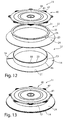
- the connecting device comprises a base element 12 and a ring element 22, which can be snapped or clipped onto the base element 12, cf. Fig.1 . Fig. 4 . Fig. 12 ,
- the base member 12 consists of a cylindrical tube 13 which has at its one end 16 a flange 14 which extends at an obtuse angle ß of 98 ° relative to the lateral surface 15 of the tube 13.
- the flange 14 has a radially extending slot 18. During assembly, the edge of the section of the lower roof track is pushed into this slot 18 and the device is then screwed around its longitudinal central axis L in the sub-roof track until the entire flange 14 below the sub-roof track to lie comes.
- a first locking element namely a circumferential groove 19, which serves for engaging a corresponding second locking element 31 on the ring member 22.
- the groove 19 comprises an oblique flank 19.1 and a steep flank 19.2, the angle between the oblique flank 19.1 and the steep flank 19.2 is an acute angle, cf.
- the second locking element On the inner side 30 of the tube 23 is near the other end 27, the second locking element, namely a rotationally symmetrical circumferential projection 31, provided, which has a sloping edge 31.1 and a steep edge 31.2.
- the steep flank 31.2 extends at an angle ⁇ of preferably 90 ° to the longitudinal central axis L of the ring element 22.
- the angle between the oblique flank 31.1 and the steep flank 31.2 is acute and corresponds to the angle between the sloping flank 19.1 and the steep flank 19.2 of the circumferential Groove 19 of the base element 12th
- the tube 23 of the ring member 22 surrounds the tube 13 of the base member 12, wherein the lateral surface 15 of the base member 12 extends along the inner side 30 of the ring member 22 and the ring member 22 along the longitudinal central axis L relative to the base member 12 is displaceable.
- the ring member 22 slides with its inner side 30 along the lateral surface 15 of the base member 12 along until the oblique flank 31.1 reaches the inclined surface 20 at the upper end 17 of the base member 12.
- the inclined surface 20 at the end 17 of the base member 12 is slightly convexly curved and terminates in the steep flank 19.2 of the groove 19.
- the inclined flank 31.1 slides along the inclined surface 20 of the base member 12 along, wherein the ring member 22 at its upper end 27 lightly is pushed outward until the circumferential projection 31 then snaps or snaps or clasps in the groove 19.
- the locking connection between the projection 31 and the groove 19 can be releasable or non-detachable.
- the latching connection is permanent, so that the outer edge 36 of the bottom 34 of the flange 24 of the ring member 22 is permanently pressed under bias against the top 21 of the flange 14 of the base member 12.
- the projection 31 and the corresponding groove 19 are barb-shaped, the angle ⁇ between the steep flanks 19.2 and 31.2 and the longitudinal central axis is an acute angle and the distance E (FIG. FIG. 5 ) between the steep flank 31.2 and the lower Outer edge 36 of the flange 24 is slightly larger than the distance F ( FIG. 2 ) between the outer edge 49 of the top 21 of the flange 14 and the steep edge 19.2 of the first locking element 19 is.
- the bias voltage is achieved in that the angle ß on the base member 12 is smaller than the angle ⁇ on the ring member 22.
- the outer lower edge 36 of the flange 24 is pressed against the upper side of the flange 14 of the base member 12. In the installed state is located between the top 21 of the flange 14 and the bottom 34 of the flange 24, the sub-roof sheet, so that a tight connection is achieved.
- a rectangular web 35 is used to attach a gasket 40th
- the gasket 40 is preferably made of a thermoplastic elastomer and elastic.
- the base element 12 and the ring element 22 are preferably made of plastic, in particular of polypropylene.
- the stability of the base member 12 is higher than that of the ring member 22, so that the ring member can be pushed onto the base member 12 with a slight deformation.
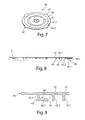
- the gasket 40 cf. Fig. 8 to 10 , has the shape of a circular disc and has on its upper side various circular cutting guides 41, 41.1, 41.2, which indicate different pipe diameters and which, if necessary, serve to guide the cutting blade when cutting out the desired circular opening.
- various circular cutting guides 41, 41.1, 41.2 which indicate different pipe diameters and which, if necessary, serve to guide the cutting blade when cutting out the desired circular opening.
- sealing webs 43 which also extend in concentric circles and serve for lateral sealing when a pipe of a concentric circle 41.1 corresponding extent in the gasket 40 is pushed.
- an L-shaped web 45 which comprises a vertically extending bottom 42 of the web portion 45.1 and a parallel to the bottom 42 extending web portion 45.2, so that between the bottom 42 and the web portion 45.2 is a circumferential pocket 46 which serves to receive the web 35 of the ring member 22.
- the length L12 of the tube 13 of the base member 12 is smaller or at most equal to the total length L22 of the tube 23 and the web 35, see. Fig. 10 . If the ring element 22 is engaged in the base element 12 (cf. Fig. 11 ), so the upward-facing side of the web 35 is above or at the same height as the end 17 of the base member 12 so that no water can reach the base member 12 from the outside.
- the sealing collar 40 By sealing the ring element 22 upwards by means of the sealing collar 40, the sealing of the ring element 22 via the flange 24 downwards and in that only the ring element 22 and not the base element 12, as is the case in the prior art, a has outer surface 25 open, a higher density is achieved.
- the elastic sealing sleeve 40 is placed on the ring element 22 and then pulled radially outward over the web 35 of the ring member 22, wherein the web 35 of the ring member 22 slips into the radially encircling pocket 46.
- the gasket 40 has different outwardly projecting ears 47, by means of which the gasket 40 can be easily grasped and slipped over the ring member 22.
- a circular cutout is first cut into the sub-roof sheet, preferably by means of a template. Subsequently, the edge of the section of the sub-roof sheet is inserted into the slot 18 in the flange 14 of the base member 12 and then the device is screwed into the web until the sub-roof sheet is above the flange 14.
- the displaceable on the base member 12 ring member 22 is pushed down until the peripheral projection 31 engages in the running on the inside of the tube 13 circumferential groove 19.
- the outer edge 36 is pressed at the same time on the underside 34 of the flange 24 of the ring member 22 from the top to the top of the sub-roof sheet, so that a tight connection is achieved.
- the gasket 40 is placed on the ring member 22, and pulled by pulling the ears 47, the gasket 40 so over the horizontal circumferential ridge 35 at the upper end 27 of the ring member 22 that the web 35 slips into the pocket 46 in the gasket 40 ,
- the device according to the invention can be used for roof passages of different diameters and different pipe diameters.
- the device according to the invention can be placed and mounted not only from the outside on the sub-roof track and, but in principle from the attic through the sub-roof track to the outside.
- the opening for the tube is preferably cut before installation in the gasket, however, the incision is possible even after installation.
- the arrangement of the grooves / projections is inverse.
- the circumferential groove 19 is not disposed on the base member 12, but on the ring member 22, where in the above-described embodiment, the circumferential projection 31 is located, and the circumferential projection 31 is not provided on the ring member 22, but on the base member 12th
- the base element 12 and the ring element 22 have a plurality of latching positions, so that the device can be used with differently thick underroof webs.
- the base element 12 has a plurality of grooves 19 and the ring element 22 has a circumferential one Projection 31 (or vice versa), so that the ring member 22 engages with its projection 31 when pressed down into the first groove 19, then into the second, etc., until it rests with its flange 24 on top of the lower roof track and not more can be pushed further down.
- the locking elements 19, 31 may be provided both at the upper end of the base member 12 and the ring member 22, as well as in the middle of the tubes 13, 23 or even at the lower end.
Abstract
Die Erfindung betrifft eine Vorrichtung zum Anschluss von Dachdurchdringungen mit einem Grundelement (12), das ein Rohr (13) mit einem Flansch (14) an seinem einen Ende (16) aufweist, und einem Ringelement (22), das ein Rohr (23) mit einem Flansch (24) an seinem einen Ende (26) aufweist, wobei das Rohr (23) des Ringelements (22) das Rohr (13) des Grundelements (12) umgreift und gegenüber diesem verschiebbar ist und die beiden Flansche (14, 24) in dieselbe Richtung weisen und an der Mantelfläche (15) des Rohrs (13) des Grundelements (12) wenigstens ein erstes Rastelement (19) und an der Innenseite (30) des Rohrs (23) des Ringelements (22) wenigstens ein zweites Rastelement (31) vorgesehen ist, und durch das Zusammenwirken des ersten Rastelements (19) mit dem zweiten Rastelement (31) eine Rastverbindung zwischen dem Grundelement (12) und dem Ringelement (22) erreicht wird.The invention relates to a device for connecting roof penetrations with a base element (12) which has a tube (13) with a flange (14) at its one end (16), and a ring member (22) having a tube (23) with a flange (24) at one end (26) thereof, the tube (23) of the ring member (22) engaging around the tube (13) of the base member (12) and is displaceable relative to the latter and the two flanges (14, 24) point in the same direction and on the lateral surface (15) of the tube (13) of the base element (12) at least one first detent element (19) and on the inner side (30) of the Pipe (23) of the ring element (22) at least one second latching element (31) is provided, and by the interaction of the first latching element (19) with the second latching element (31) has a latching connection between the base element (12) and the ring element (22) is reached.
Description
Die vorliegende Erfindung betrifft eine Vorrichtung zum Anschluss von Dachdurchdringungen an das jeweilige Unterdach.The present invention relates to a device for connecting roof penetrations to the respective sub-roof.
Der Anschluss des Rohres der Sanitärbelüftung und/oder Raumentlüftung an das Dunstrohr eines Durchgangsziegels erfolgt im Allgemeinen dadurch, dass eine Öffnung in die Unterdachbahn geschnitten, das Dunstrohr durch die Öffnung geführt, in der Regel mit Klebeband oder sonstigem abgedichtet und auf das Dunstrohr von unten ein flexibler Schlauchanschluss zur Verbindung mit dem Belüftungsrohr aufgeschoben wird.The connection of the pipe of sanitary ventilation and / or room ventilation to the vent pipe of a through-tile is generally carried out by cutting an opening in the sub-roof sheet, passing the vent pipe through the opening, usually sealed with adhesive tape or the like, and onto the vent pipe from below flexible hose connection for connection to the ventilation pipe is pushed.
Im Regelwerk des Deutschen Dachdeckerhandwerks findet sich im "Merkblatt für Unterdächer, Unterdeckungen, Unterspannungen" die Forderung, dass Einbauteile und Durchdringungen bei Unterdeckungen und Unterdächern wasserdicht eingefasst und an die Zusatzmaßnahme anzuschließen sind.The regulations of the German Roofing Trade find in the "Leaflet for sub-roofs, short-falls, undervoltages" the requirement that built-in parts and penetrations for undercovers and sub-roofs are edged waterproof and connected to the additional measure.
Bei runden Rohrdurchführungen ist dies nicht ganz einfach herzustellen, da ein Ankleben der Unterdachbahn an ein solches Rohr relativ kompliziert ist und Leckagemöglichkeiten bietet.In round pipe penetrations, this is not easy to produce, since sticking the sub-roof sheet to such a pipe is relatively complicated and offers leakage opportunities.
Die
Weiterhin ist ein Anschlussring bekannt, der aus einem Grundelement mit einem ersten zylindrischen Rohrstück mit einem sich an dem Rohrende anschließenden Flansch besteht und einem elastischen Ring, der auf das Rohr aufgestülpt ist und in eine umlaufende Nut auf der Außenseite des Rohrstücks eingreift. Der elastische Ring kann nach oben und nach unten geklappt werden. Der Anschlussring wird nun zunächst mit hochgeklapptem Ring mittels eines in dem Flansch des ersten Rohrstücks vorgesehenen Spalts in den Ausschnitt in der Unterdachbahn eingedreht, bis der Flansch unterhalb der Unterdachbahn liegt. Anschließend wird der elastische Ring nach unten geklappt, so dass er mit der Unterseite seines Randes auf der Unterdachbahn aufliegt und die Unterdachbahn zwischen dem Flansch und dem Ring eingeklemmt wird. Das nach außen weisende Ende des Rohrstücks ist mit einer Dichtungsmanschette abgedichtet.Furthermore, a connection ring is known, which consists of a base member having a first cylindrical pipe section with a flange adjoining the pipe end and an elastic ring which is slipped onto the pipe and engages in a circumferential groove on the outside of the pipe section. The elastic ring can be folded up and down. The connecting ring is then first screwed with folded-up ring by means of a provided in the flange of the first pipe section gap in the cutout in the sub-roof sheet, until the flange lies below the lower roof track. Subsequently, the elastic ring is folded down so that it rests with the underside of its edge on the sub-roof track and the sub-roof track between the flange and the ring is clamped. The outwardly facing end of the pipe section is sealed with a gasket.
Diese Vorrichtung ermöglicht aufgrund der Flexibilität des Rings ein mehrmaliges Hoch- und Runterklappen. Nachteilig ist allerdings, dass die Dichtigkeit der Vorrichtung insbesondere infolge von Witterungseinflüssen und bei stehendem Wasser mit der Zeit nachlässt.This device allows due to the flexibility of the ring a repeated up and down flaps. The disadvantage, however, is that the tightness of the device decreases in particular due to weather conditions and stagnant water over time.
Die Aufgabe der vorliegenden Erfindung besteht darin, eine flexible Vorrichtung zum Anschluss von Dachdurchgängen bereit zu stellen, die auch bei stehendem Wasser über lange Zeit die Dichtigkeit beibehält. Diese Aufgabe wird durch die Merkmale des Anspruchs 1 gelöst.The object of the present invention is to provide a flexible device for connecting roof passages, which maintains the tightness even when the water is standing for a long time. This object is solved by the features of claim 1.
Gemäß einem ersten Aspekt der Erfindung wird eine Vorrichtung zum Anschluss von Dachdurchdringungen bereitgestellt, mit einem Grundelement , das ein Rohr mit einem Flansch an seinem einen Ende aufweist, und einem Ringelement, das ein Rohr mit einem Flansch an seinem einen Ende aufweist, wobei das Rohr des Ringelements das Rohr des Grundelements umgreift und gegenüber diesem verschiebbar ist. Die beiden Flansche weisen in dieselbe Richtung, und an der Mantelfläche des Rohrs des Grundelements ist wenigstens ein erstes Rastelement und an der Innenseite des Rohrs des Ringelements ist wenigstens ein zweites Rastelement vorgesehen, und durch das Zusammenwirken des ersten Rastelements mit dem zweiten Rastelement wird eine Rastverbindung zwischen dem Grundelement und dem Ringelement erreicht.According to a first aspect of the invention there is provided an apparatus for connecting roof penetrations, comprising a base member having a pipe with a flange at one end thereof and a ring member having a pipe with a flange at one end thereof, the pipe of the ring element surrounds the tube of the base element and is displaceable relative thereto. The two flanges point in the same direction, and on the lateral surface of the tube of the base element is at least a first locking element and on the inside of the tube of the ring member is provided at least a second locking element, and by the interaction of the first locking element with the second locking element is a latching connection reached between the base element and the ring element.
Gemäß einigen Ausführungsformen ist das wenigstens eine erste Rastelement eine umlaufende Nut und das wenigstens eine zweite Rastelement ein umlaufender Vorsprung oder umgekehrt.According to some embodiments, the at least one first latching element is a circumferential groove and the at least one second latching element is a circumferential projection or vice versa.
Gemäß einigen Ausführungsformen kann der Winkel ß zwischen der Mantelfläche des Grundelements und der Oberfläche des Flansches in die dem Flansch entgegengesetzte Richtung kleiner als der Winkel γ zwischen der Mantelfläche des Ringelements und der Oberfläche des Flansches in die dem Flansch entgegengesetzte Richtung sein und die Winkel ß, γ sind stumpfe Winkel.According to some embodiments, the angle β between the surface of the base member and the surface of the flange in the direction opposite to the flange may be smaller than the angle γ between the surface of the ring member and the surface of the flange in the direction opposite to the flange and the angles β, γ are obtuse angles.
In einer bevorzugten Variante der Vorrichtung beträgt der Winkel ß zwischen 93° und 140°, bevorzugt zwischen 100° und 120° und/oder der Winkel γ zwischen 91° und 120°, vorzugsweise zwischen 95° und 105°.In a preferred variant of the device, the angle β is between 93 ° and 140 °, preferably between 100 ° and 120 ° and / or the angle γ between 91 ° and 120 °, preferably between 95 ° and 105 °.
In einer weiteren Variante der Vorrichtung weist das Ringelement an seinem dem Flansch gegenüberliegenden Ende einen umlaufenden, nach außen gerichteten Steg auf, gemäß einer anderen Variante kann das Ringelement auch ein Schraubgewinde aufweisen.In a further variant of the device, the ring element has at its end opposite the flange a circumferential, outwardly directed web, according to another variant, the ring element may also have a screw thread.
Vorzugsweise ist die in Längsrichtung L gemessene Länge L12 des Rohres des Grundelements gleich oder kleiner ist als die Länge L22 der Summe aus der Länge des Rohres und der Länge des Stegs des Ringelements .Preferably, the length L12 of the tube of the base member measured in the longitudinal direction L is equal to or smaller than the length L22 of the sum of the length of the tube and the length of the ridge of the ring member.
Vorzugsweise ist zusätzlich eine Dichtungsmanschette vorgesehen. In einer bevorzugten Variante nimmt die Dichtungsmanschette in einer umlaufenden Tasche an ihrer Unterseite den umlaufenden, nach außen gerichteten Steg des Ringelements auf. In einer weiteren Variante kann die Dichtungsmanschette ein Innengewinde aufweisen, das zu dem Schraubgewinde am Ringelement korrespondiert.Preferably, a sealing sleeve is additionally provided. In a preferred variant, the sealing sleeve receives in a circumferential pocket on its underside on the circumferential, outwardly directed web of the ring element. In a further variant, the sealing sleeve can have an internal thread which corresponds to the screw thread on the ring element.
Gemäß einer weiteren Variante weist die Dichtungsmanschette an ihrer Oberseite verschiedene kreisförmige Schneidführungen auf.According to a further variant, the sealing sleeve on its upper side on various circular cutting guides.
Gemäß einer weiteren Ausführungsform sind an der Unterseite der Dichtungsmanschette kreisförmige Dichtungsstege angeordnet.According to a further embodiment, circular sealing webs are arranged on the underside of the sealing sleeve.
Eine weitere Variante sieht vor, dass der Flansch des Grundelements einen sich radial erstreckenden Schlitz aufweist.Another variant provides that the flange of the base member has a radially extending slot.
Darüber hinaus kann gemäß einer weiteren Variante der Vorrichtung das erste Rastelement und/oder das zweite Rastelement eine schräge Flanke und eine steile Flanke aufweisen.In addition, according to a further variant of the device, the first detent element and / or the second detent element have an oblique flank and a steep flank.
Vorzugsweise ist der Winkel zwischen der schrägen Flanke und der steilen Flanke ein spitzer Winkel.Preferably, the angle between the oblique flank and the steep flank is an acute angle.
In einer bevorzugten Ausführungsform ist die Dichtungsmanschette elastisch, insbesondere aus einem thermoplastischen Elastomer, und das Grundelement und das Ringelement aus Kunststoff, insbesondere aus Polypropylen, Polyethylen oder PVC.In a preferred embodiment, the gasket is elastic, in particular of a thermoplastic elastomer, and the basic element and the ring element made of plastic, in particular polypropylene, polyethylene or PVC.
Eine weitere Variante der Vorrichtung sieht vor, dass die Dichtungsmanschette verschiedene nach außen weisende Ohren aufweist.A further variant of the device provides that the gasket has different outwardly facing ears.
Gemäß einer weiteren Variante der Vorrichtung sind die Rastelemente am oberen Ende des Grundelements und des Ringelements vorgesehen und/oder in der Mitte der Rohre oder eher am unteren Ende der Rohre.According to a further variant of the device, the latching elements are provided at the upper end of the base element and the ring element and / or in the middle of the tubes or rather at the lower end of the tubes.
Die erfindungsgemäße Anschlussvorrichtung umfasst ein Grundelement mit einem Rohr und einem Flansch und ein Ringelement mit einem Rohr und einem Flansch, das Rohr des Ringelements umgreift das Rohr des Grundelements und ist gegenüber diesem verschiebbar, und an der Mantelfläche des Rohrs des Grundelements ist ein erstes Rastelement und an der Innenfläche des Rohrs des Ringelements ein zweites Rastelement vorgesehen. Während des Verschiebens verrastet nun das eine Rastelement mit dem anderen Rastelement, die Rastelemente wirken zusammen, und es wird eine Rastverbindung zwischen dem Grundelement und dem Ringelement erreicht.The connection device according to the invention comprises a base element with a tube and a flange and a ring element with a tube and a flange, the tube of the ring element engages around the tube of the base element and is displaceable relative thereto, and on the lateral surface of the tube of the base element is a first latching element and provided on the inner surface of the tube of the ring member, a second locking element. During the displacement now locks the one locking element with the other locking element, the locking elements cooperate, and it is achieved a latching connection between the base member and the ring member.
In der Position, in der die beiden Rastelemente verrasten, wird gleichzeitig der Flansch des Ringelements gegen den Flansch des Grundelements gedrückt, so dass die zwischen den beiden Flanschen befindliche Unterdachbahn abgedichtet wird.In the position in which lock the two locking elements, at the same time the flange of the ring member is pressed against the flange of the base member, so that the located between the two flanges sub-roof sheet is sealed.
Da das Pressen des Flansches des Ringelements gegen den Flansch des Grundelements erfindungsgemäß durch die Rastverbindung und nicht durch das Umklappen elastischer Teile erfolgt, können die auf die Materialermüdung des elastischen Rings und den Elastizitätsverlust des elastischen Teils zurückzuführenden Nachteile des bekannten Anschlussrings vermieden und eine langanhaltende Dichtigkeit erreicht werden.Since the pressing of the flange of the ring member against the flange of the base member according to the invention by the locking connection and not by folding elastic parts, the attributable to the fatigue of the elastic ring and the loss of elasticity of the elastic part disadvantages of the known connection ring can be avoided and achieved a long-lasting tightness become.
Die erfindungsgemäße Vorrichtung mit den Rastelementen weist darüber hinaus eine höhere Flexibilität auf, da auch mehr als zwei Rastelemente oder mehr als eine Rastverbindung vorgesehen sein können. Dies hat den Vorteil, dass der Anpressdruck des Flansches des Ringelements auf den Flansch des Grundelements wählbar ist und sich die Anschlussvorrichtung somit für unterschiedlich dicke Unterdachbahnen verwenden lässt.The device according to the invention with the locking elements also has a higher flexibility, since more than two locking elements or more than one locking connection can be provided. This has the advantage that the contact pressure of the flange of the ring element can be selected on the flange of the base element and thus the connection device can be used for different thickness sub-roof sheets.
Die Rastelemente können eine Nut oder ein korrespondierend geformter Vorsprung oder Erhöhung sein. Vorzugsweise ist die Rastverbindung nicht lösbar, so dass eine Materialschwächung durch wiederholtes Öffnen und Schließen vermieden wird.The locking elements may be a groove or a correspondingly shaped projection or elevation. Preferably, the latching connection is not detachable, so that a material weakening is avoided by repeated opening and closing.
Die Rastverbindung kann auch als Schnapp- oder Klickverbindung bezeichnet werden.The locking connection can also be referred to as a snap or click connection.
Um zu erreichen, dass der Flansch des Ringelements permanent gegen den Flansch des Grundelements gepresst wird und die Verbindung zu der Unterdachbahn somit dicht ist, ist der Winkel ß zwischen der Mantelfläche und der Oberfläche des Flanschs des Grundelements in die dem Flansch entgegengesetzte Richtung kleiner als der Winkel γ zwischen der Mantelfläche des Ringelements und der Oberfläche des Flanschs, gemessen in die dem Flansch entgegengesetzte Richtung, wobei die Winkel ß, γ stumpfe Winkel sind.In order to achieve that the flange of the ring element is pressed permanently against the flange of the base element and the connection to the sub-roof track is thus tight, the angle β between the lateral surface and the surface of the flange of the base element in the direction opposite to the flange is smaller than that Angle γ between the lateral surface of the ring element and the surface of the flange, measured in the direction opposite to the flange, wherein the angles ß, γ are obtuse angles.
Im oberen Bereich der Vorrichtung kann die Dichtigkeit dadurch erreicht werden, dass ein sich rechtwinklig von dem Rohr des Ringelements erstreckender Steg vorgesehen ist, der in einer Tasche der Dichtungsmanschette aufgenommen wird. Hierdurch wird eine flüssigkeitsdichte Verbindung von der Dichtungsmanschette über das Ringelement bis zur Oberseite der Unterdachbahn erzielt. Anders als im Stand der Technik wird die Dichtigkeit erfindungsgemäß über das Ringelement und nicht über das Grundelement erreicht.In the upper part of the device, the tightness can be achieved by providing a web extending at right angles from the tube of the ring element, which is received in a pocket of the sealing collar. As a result, a liquid-tight connection is achieved from the gasket over the ring member to the top of the sub-roof sheet. Unlike in the prior art, the sealing is achieved according to the invention via the ring member and not via the base member.
In einer anderen Variante weist das Ringelement im oberen Bereich seiner Außenseite ein Schraubgewinde auf und die Dichtungsmanschette ein korrespondierendes Innengewinde, so dass eine flüssigkeitsdichte Verbindung erzielt wird.In another variant, the ring element in the upper region of its outer side has a screw thread and the sealing sleeve has a corresponding internal thread, so that a liquid-tight connection is achieved.
Die erfindungsgemäße Anschlussvorrichtung lässt sich universell für alle Dachdurchdringungen einsetzen, nicht nur zum Anschluss von Belüftungs- und Dunstrohren, sondern auch für den Anschluss von Photovoltaikanlagen, Antennenmasten, Solarthermieanlagen oder Gasthermen.The connection device according to the invention can be used universally for all roof penetrations, not only for the connection of ventilation and fume pipes, but also for the connection of photovoltaic systems, antenna masts, solar thermal systems or gas heating.
Die Dichtungsmanschette weist an ihrer Oberseite verschiedene kreisförmige Schneidführungen auf. An die Kanten der Schneidführungen können Schneidmesser angelegt werden, um die gewünschte kreisförmige Öffnung in der Manschette für den jeweilig gewünschten Rohrdurchmesser in der richtigen Größe auf einfache Weise schneiden zu können. Zur Abdichtung weist die Manschette an ihrer Unterseite korrespondierend zu der kreisförmigen Schneidführung nur geringfügig gegenüber dieser nach außen versetzt kreisförmige Dichtungsstege auf, die zur Anlage an der Mantelfläche des in die Manschettenöffnung hineingeschobenen Rohrs, Anschlusses, Masts etc. dienen.The gasket has on its upper side various circular cutting guides. Cutting blades may be applied to the edges of the cutting guides to easily locate the desired circular opening in the sleeve for the desired pipe diameter in the correct size to be able to cut. For sealing, the sleeve has on its underside corresponding to the circular cutting guide only slightly opposite to this offset outwardly circular sealing webs, which serve to rest against the lateral surface of the pushed into the sleeve opening pipe, connection, mast, etc.
Ebenso können schwache ringförmige Mittel an der Dichtungsmanschette vorgesehen sein.Likewise, weak annular means may be provided on the gasket.
Die Erfindung wird nachfolgend anhand von Ausführungsbeispielen näher beschreiben. Es zeigen:
- Fig. 1:
- eine perspektivische Ansicht auf das Grundelement von schräg oben,
- Fig. 2:
- das Grundelement aus
Figur 1 im Schnitt, - Fig. 3:
- das Detail A aus
Figur 2 , - Fig. 4:
- eine perspektivische Ansicht auf das Ringelement von schräg oben,
- Fig. 5:
- das Ringelement aus
Figur 4 im Schnitt, - Fig. 6:
- den Ausschnitt B aus
Figur 5 , - Fig. 7:
- eine perspektivische Ansicht auf die Dichtungsmanschette von schräg oben,
- Fig. 8:
- den Schnitt durch die Manschette aus
Figur 7 , - Fig. 9:
- das Detail C aus
Figur 8 , - Fig.10:
- den linken Bereich des Ringelements vor dem Einrasten des Vorsprungs in die Nut des Grundelements,
- Fig.11:
- den linken Bereich des Ringelements nach dem Einrasten des Vorsprungs in die Nut des Grundelements,
- Fig.12:
- eine perspektivische Explosionsansicht der erfindungsgemäßen Anschlussvorrichtung und
- Fig.13:
- eine perspektivische Ansicht der (zusammengesetzten)
Anschlussvorrichtung aus Figur 12 .
- Fig. 1:
- a perspective view of the base element obliquely from above,
- Fig. 2:
- the basic element
FIG. 1 on average, - 3:
- the detail A off
FIG. 2 . - 4:
- a perspective view of the ring member obliquely from above,
- Fig. 5:
- the ring element
FIG. 4 on average, - Fig. 6:
- the detail B off
FIG. 5 . - Fig. 7:
- a perspective view of the gasket from diagonally above,
- Fig. 8:
- cut through the cuff
FIG. 7 . - Fig. 9:
- the detail C off
FIG. 8 . - Figure 10:
- the left region of the ring element before the projection engages in the groove of the base element,
- Figure 11:
- the left region of the ring element after the projection engages in the groove of the base element,
- Figure 12:
- an exploded perspective view of the connecting device according to the invention and
- Figure 13:
- a perspective view of the (composite) connection device
FIG. 12 ,
Die Anschlussvorrichtung umfasst ein Grundelement 12 und ein Ringelement 22, das auf das Grundelement 12 aufgerastet oder aufgeklipst werden kann, vgl.
Das Grundelement 12 besteht aus einem zylindrischen Rohr 13, das an seinem einen Ende 16 einen Flansch 14 aufweist, der sich unter einem stumpfen Winkel ß von 98° gegenüber der Mantelfläche 15 des Rohrs 13 erstreckt.The
Der Flansch 14 besitzt einen sich radial erstreckenden Schlitz 18. Bei der Montage wird in diesen Schlitz 18 der Rand des Ausschnitts der Unterdachbahn hineingeschoben und die Vorrichtung dann solange um ihre Längsmittelachse L in die Unterdachbahn eingedreht, bis der gesamte Flansch 14 unterhalb der Unterdachbahn zum Liegen kommt.The
An dem anderen Ende 17 des Rohrs 13 des Grundelements 12 ist in dessen Mantelfläche 15 ein erstes Rastelement, nämlich eine umlaufende Nut 19, die zum Einrasten eines korrespondierenden zweiten Rastelements 31 an dem Ringelement 22 dient. Die Nut 19 umfasst eine schräge Flanke 19.1 und eine steile Flanke 19.2, der Winkel zwischen der schrägen Flanke 19.1 und der steilen Flanke 19.2 ist ein spitzer Winkel, vgl.
Das Ringelement 22 besteht ebenfalls aus einem zylindrischen Rohr 23, das an seinem einen Ende 26 ebenfalls einen Flansch 24 aufweist, der sich unter einem stumpfen Winkel von γ = 110°, somit einem Winkel γ, der größer als der Winkel ß des Grundelements 12 ist, gegenüber der Mantelfläche 25 des Rohrs 23 des Ringelements 22 erstreckt, vgl.
An der Innenseite 30 des Rohrs 23 ist nahe dem anderen Ende 27 das zweite Rastelement, nämlich ein rotationssymmetrisch umlaufender Vorsprung 31, vorgesehen, der eine schräge Flanke 31.1 und eine steile Flanke 31.2 besitzt. Die steile Flanke 31.2 verläuft unter einem Winkel α von vorzugsweise 90° zur Längsmittelachse L des Ringelements 22. Der Winkel zwischen der schrägen Flanke 31.1 und der steilen Flanke 31.2 ist spitz und entspricht dem Winkel zwischen der schrägen Flanke 19.1 und der steilen Flanke 19.2 der umlaufenden Nut 19 des Grundelements 12.On the
Das Rohr 23 des Ringelements 22 umgreift das Rohr 13 des Grundelements 12, wobei die Mantelfläche 15 des Grundelements 12 sich entlang der Innenseite 30 des Ringelements 22 erstreckt und das Ringelement 22 entlang der Längsmittelachse L gegenüber dem Grundelement 12 verschiebbar ist.The
Wird das Ringelement 22 nun gemäß Pfeil D in
In Abhängigkeit von den Abmessungen der Nut 19 und des Vorsprungs 31, den Wandstärken der Rohre 13, 23 und dem Material des Grundelements 12 und des Ringelements 22 kann die Rastverbindung zwischen dem Vorsprung 31 und der Nut 19 lösbar oder nicht lösbar sein.Depending on the dimensions of the
Bevorzugt ist das einmal eingerastete Ringelement 22 nicht mehr von dem Grundelement 12 entfernbar, d.h. die Rastverbindung ist dauerhaft, so dass der äußere Rand 36 der Unterseite 34 des Flansches 24 des Ringelements 22 permanent unter Vorspannung gegen die Oberseite 21 des Flanschs 14 des Grundelements 12 gepresst wird.Preferably, once the
Dies kann dadurch erreicht werden, dass der Vorsprung 31 und die korrespondierende Nut 19 widerhakenförmig ausgebildet sind, der Winkel α zwischen den steilen Flanken 19.2 und 31.2 und der Längsmittelachse ein spitzer Winkel ist und der Abstand E (
Die Vorspannung wird dadurch erreicht, dass der Winkel ß am Grundelement 12 kleiner als der Winkel γ am Ringelement 22 ist. Durch die Rastverbindung 19, 31 wird der äußere untere Rand 36 des Flansches 24 gegen die Oberseite des Flansches 14 des Grundelements 12 gepresst. Im eingebauten Zustand befindet sich zwischen der Oberseite 21 des Flansches 14 und der Unterseite 34 des Flansches 24 die Unterdachbahn, so dass eine dichte Verbindung erreicht wird.The bias voltage is achieved in that the angle ß on the
Am anderen Ende 27 des Ringelements 22 erstreckt sich rechtwinklig zu der Mantelfläche 25 des Rohrs 23 ein rechtwinkliger Steg 35. Dieser Steg 35 dient zur Befestigung einer Dichtungsmanschette 40.At the
Nachdem das Ringelement 22 mit seinem Flansch 24 auf der Unterdachbahn aufliegt und der Flansch 24 über das Rohr 23 in den Steg 35 übergeht, der, wie anschließend beschrieben, flüssigkeitsdicht in einer Tasche in der Dichtungsmanschette 40 aufgenommen wird, kann - anders als bei den bislang bekannten Anschlussvorrichtungen - kein stehendes Wasser in den Durchgang eindringen.After the
Die Dichtungsmanschette 40 ist vorzugsweise aus einem thermoplastischen Elastomer aus und elastisch.The
Das Grundelement 12 und das Ringelement 22 sind vorzugsweise aus Kunststoff, insbesondere aus Polypropylen. Vorzugsweise ist die Stabilität des Grundelements 12 höher als die des Ringelements 22, so dass sich das Ringelement auf das Grundelement 12 unter einer geringen Verformung aufschieben lässt.The
Die Dichtungsmanschette 40, vgl.
An der Unterseite 42 der Dichtungsmanschette 40 verläuft nahe dem äußeren Rand 44 der Dichtungsmanschette 40 ein L-förmiger Steg 45, der einen senkrecht der Unterseite 42 verlaufenden Stegabschnitt 45.1 und einen parallel der Unterseite 42 verlaufenden Stegabschnitt 45.2 umfasst, so dass zwischen der Unterseite 42 und dem Stegabschnitt 45.2 eine umlaufende Tasche 46 ist, die zur Aufnahme des Stegs 35 des Ringelements 22 dient.At the bottom 42 of the sealing
Die Länge L12 des Rohrs 13 des Grundelements 12 ist kleiner oder maximal gleich der Gesamtlänge L22 des Rohrs 23 und des Stegs 35, vgl.
Die elastische Dichtungsmanschette 40 wird auf das Ringelement 22 aufgelegt und dann radial nach außen über den Steg 35 des Ringelements 22 gezogen, wobei der Steg 35 des Ringelements 22 in die radial umlaufende Tasche 46 hineinrutscht.The
Um ein besseres Aufziehen der Dichtungsmanschette 40 auf das Ringelement 22 zu ermöglichen, weist die Dichtungsmanschette 40 verschiedene nach außen stehende Ohren 47 auf, mittels denen die Dichtungsmanschette 40 einfacher ergriffen und über das Ringelement 22 gestülpt werden kann.In order to allow a better mounting of the
Bei der Montage der Anschlussvorrichtung wird zunächst, vorzugsweise mittels einer Schablone, ein kreisrunder Ausschnitt in die Unterdachbahn geschnitten. Anschließend wird der Rand des Ausschnitts der Unterdachbahn in den Schlitz 18 im Flansch 14 des Grundelements 12 gesteckt und die Vorrichtung dann in die Bahn eingedreht, bis die Unterdachbahn oberhalb des Flansches 14 ist.During assembly of the connecting device, a circular cutout is first cut into the sub-roof sheet, preferably by means of a template. Subsequently, the edge of the section of the sub-roof sheet is inserted into the
Nun wird das auf dem Grundelement 12 verschiebbare Ringelement 22 nach unten geschoben, bis der umlaufende Vorsprung 31 in die an der Innenseite des Rohrs 13 verlaufende umlaufende Nut 19 einrastet. Hierdurch wird gleichzeitig der äußere Rand 36 an der Unterseite 34 des Flansches 24 des Ringelements 22 von oben auf die Oberseite der Unterdachbahn gepresst, so dass eine dichte Verbindung erreicht wird.Now, the displaceable on the
Nun wird die Dichtungsmanschette 40 auf das Ringelement 22 gelegt, und durch Zug an den Ohren 47 die Dichtungsmanschette 40 so über den horizontal umlaufenden Steg 35 am oberen Ende 27 des Ringelements 22 gezogen, dass der Steg 35 in die Tasche 46 in der Dichtungsmanschette 40 rutscht.Now, the
Hierdurch wird auf einfache Weise eine dichte Verbindung erreicht, selbst bei stehendem Wasser kann kein Wasser in die Öffnung eindringen.As a result, a tight connection is achieved in a simple manner, even with stagnant water, no water can penetrate into the opening.
Die erfindungsgemäße Vorrichtung kann für Dachdurchgänge unterschiedlicher Durchmesser und unterschiedliche Rohrdurchmesser eingesetzt werden.The device according to the invention can be used for roof passages of different diameters and different pipe diameters.
Nachdem die Vorrichtung mittels der beiden Flansche 14, 24 auf beiden Seiten der Unterdachbahn wirksam abdichtet, kann die erfindungsgemäße Vorrichtung nicht nur von außen auf die Unterdachbahn aufgesetzt und montiert werden, sondern im Prinzip auch vom Dachgeschoss durch die Unterdachbahn nach außen.After the device effectively seals by means of the two
Die Öffnung für das Rohr wird vorzugsweise vor dem Einbau in die Dichtungsmanschette eingeschnitten, allerdings ist der Einschnitt auch nach dem Einbau möglich.The opening for the tube is preferably cut before installation in the gasket, however, the incision is possible even after installation.
In einer weiteren Variante ist die Anordnung der Nuten/Vorsprünge invers. Die umlaufende Nut 19 ist nicht am Grundelement 12 angeordnet, sondern am Ringelement 22, dort, wo sich in der oben beschriebenen Ausführungsform der umlaufende Vorsprung 31 befindet, und der umlaufende Vorsprung 31 ist nicht am Ringelement 22 vorgesehen, sondern am Grundelement 12.In a further variant, the arrangement of the grooves / projections is inverse. The
In einer weiteren Variante weist das Grundelement 12 und das Ringelement 22 mehrere Rastpositionen auf, so dass die Vorrichtung bei unterschiedlich dicken Unterdachbahnen eingesetzt werden kann. So weist das Grundelement 12 beispielsweise mehrere Nuten 19 auf und das Ringelement 22 einen umlaufenden Vorsprung 31 (oder umgekehrt), so dass das Ringelement 22 mit seinem Vorsprung 31 beim nach unten Drücken in die erste Nut 19 einrastet, dann in die zweite etc., bis es dann mit seinem Flansch 24 auf der Oberseite der Unterdachbahn anliegt und nicht mehr weiter nach unten gedrückt werden kann.In a further variant, the
Generell können die Rastelemente 19, 31 sowohl am oberen Ende des Grundelements 12 und des Ringelements 22 vorgesehen sein, als auch in der Mitte der Rohre 13, 23 oder auch eher an deren unterem Ende.In general, the locking
Claims (17)
und einem Ringelement (22), das ein Rohr (23) mit einem Flansch (24) an seinem einen Ende (26) aufweist,
dadurch gekennzeichnet, dass das Rohr (23) des Ringelements (22) das Rohr (13) des Grundelements (12) umgreift und gegenüber diesem verschiebbar ist und die beiden Flansche (14, 24) in dieselbe Richtung weisen und an der Mantelfläche (15) des Rohrs (13) des Grundelements (12) wenigstens ein erstes Rastelement (19) und an der Innenseite (30) des Rohrs (23) des Ringelements (22) wenigstens ein zweites Rastelement (31) vorgesehen ist, und durch das Zusammenwirken des ersten Rastelements (19) mit dem zweiten Rastelement (31) eine Rastverbindung zwischen dem Grundelement (12) und dem Ringelement (22) erreicht wird.Device for connecting roof penetrations with a base element (12), which has a tube (13) with a flange (14) at its one end (16),
and a ring member (22) having a tube (23) with a flange (24) at one end (26) thereof,
characterized in that the tube (23) of the ring element (22) surrounds the tube (13) of the base element (12) and is displaceable relative thereto and the two flanges (14, 24) point in the same direction and on the lateral surface (15). at least one first detent element (19) is provided on the tube (13) of the base element (12) and at least one second detent element (31) is provided on the inner side (30) of the tube (23) of the ring element (22), and by the interaction of the first one Locking element (19) with the second latching element (31) a latching connection between the base element (12) and the ring element (22) is achieved.
Priority Applications (10)
| Application Number | Priority Date | Filing Date | Title |
|---|---|---|---|
| EP16150125.9A EP3190241A1 (en) | 2016-01-05 | 2016-01-05 | Device for connection with roof penetrating devices |
| RS20211386A RS62655B1 (en) | 2016-01-05 | 2017-01-04 | Device for connection with roof penetrating devices |
| HRP20211738TT HRP20211738T1 (en) | 2016-01-05 | 2017-01-04 | Device for connection with roof penetrating devices |
| EP17700055.1A EP3400347B1 (en) | 2016-01-05 | 2017-01-04 | Device for connection with roof penetrating devices |
| PCT/EP2017/050128 WO2017118653A1 (en) | 2016-01-05 | 2017-01-04 | Device for connection with roof penetrating devices |
| PL17700055T PL3400347T3 (en) | 2016-01-05 | 2017-01-04 | Device for connection with roof penetrating devices |
| SI201730990T SI3400347T1 (en) | 2016-01-05 | 2017-01-04 | Device for connection with roof penetrating devices |
| HUE17700055A HUE056806T2 (en) | 2016-01-05 | 2017-01-04 | Device for connection with roof penetrating devices |
| ES17700055T ES2898691T3 (en) | 2016-01-05 | 2017-01-04 | Device for connection with roof penetration devices |
| DK17700055.1T DK3400347T3 (en) | 2016-01-05 | 2017-01-04 | Device for connection to roof-carrying devices |
Applications Claiming Priority (1)
| Application Number | Priority Date | Filing Date | Title |
|---|---|---|---|
| EP16150125.9A EP3190241A1 (en) | 2016-01-05 | 2016-01-05 | Device for connection with roof penetrating devices |
Publications (1)
| Publication Number | Publication Date |
|---|---|
| EP3190241A1 true EP3190241A1 (en) | 2017-07-12 |
Family
ID=55072520
Family Applications (2)
| Application Number | Title | Priority Date | Filing Date |
|---|---|---|---|
| EP16150125.9A Withdrawn EP3190241A1 (en) | 2016-01-05 | 2016-01-05 | Device for connection with roof penetrating devices |
| EP17700055.1A Active EP3400347B1 (en) | 2016-01-05 | 2017-01-04 | Device for connection with roof penetrating devices |
Family Applications After (1)
| Application Number | Title | Priority Date | Filing Date |
|---|---|---|---|
| EP17700055.1A Active EP3400347B1 (en) | 2016-01-05 | 2017-01-04 | Device for connection with roof penetrating devices |
Country Status (9)
| Country | Link |
|---|---|
| EP (2) | EP3190241A1 (en) |
| DK (1) | DK3400347T3 (en) |
| ES (1) | ES2898691T3 (en) |
| HR (1) | HRP20211738T1 (en) |
| HU (1) | HUE056806T2 (en) |
| PL (1) | PL3400347T3 (en) |
| RS (1) | RS62655B1 (en) |
| SI (1) | SI3400347T1 (en) |
| WO (1) | WO2017118653A1 (en) |
Families Citing this family (1)
| Publication number | Priority date | Publication date | Assignee | Title |
|---|---|---|---|---|
| DE202021004168U1 (en) | 2021-09-01 | 2022-11-28 | Creaton Gmbh | Device for connection to roof penetrations |
Citations (10)
| Publication number | Priority date | Publication date | Assignee | Title |
|---|---|---|---|---|
| FR2031257A5 (en) * | 1969-02-01 | 1970-11-13 | Dynamit Nobel Ag | |
| DE2507045A1 (en) * | 1975-02-19 | 1976-09-09 | Dallmer Helmuth Fa | Gutter inlet for flat roofs - incorporates clamping ring with socket, to clamp roofing foil |
| US5036636A (en) * | 1987-12-22 | 1991-08-06 | Hasty William E | Multiple size vent-pipe roof flashing |
| DE4430657A1 (en) | 1994-08-29 | 1996-03-07 | Johannes Kloeber | Device for sealing a roof duct |
| DE29721602U1 (en) * | 1997-12-06 | 1998-02-19 | Schulte Guenter | Roof duct for a pipeline, especially ventilation pipeline |
| DE19840593A1 (en) * | 1998-09-05 | 2000-03-16 | Oskar Fleck | Flat roof drainage gully has two funnel-shaped hollow bodies with locking elements, and clamp elements to hold roofing material |
| DE29824547U1 (en) * | 1998-09-05 | 2001-07-26 | Fleck Oskar | Roof ventilation device, especially flat roof ventilation device |
| US20050150176A1 (en) * | 2003-12-31 | 2005-07-14 | Craig Erekson | Pipe flashing UV shield |
| NL1025877C2 (en) * | 2004-04-02 | 2005-10-07 | V O F Naadloze Aluminium Goots | Drain for gutter comprising inner and outer flanged tubular parts, includes drainage passage for any water accumulated in space between flanges |
| DE202010005159U1 (en) * | 2010-03-31 | 2010-09-02 | Karl Grumbach Gmbh & Co. Kg | Fire protection gully, fan and pipe duct for roof, ceiling and wall |
-
2016
- 2016-01-05 EP EP16150125.9A patent/EP3190241A1/en not_active Withdrawn
-
2017
- 2017-01-04 PL PL17700055T patent/PL3400347T3/en unknown
- 2017-01-04 WO PCT/EP2017/050128 patent/WO2017118653A1/en active Application Filing
- 2017-01-04 SI SI201730990T patent/SI3400347T1/en unknown
- 2017-01-04 DK DK17700055.1T patent/DK3400347T3/en active
- 2017-01-04 HU HUE17700055A patent/HUE056806T2/en unknown
- 2017-01-04 RS RS20211386A patent/RS62655B1/en unknown
- 2017-01-04 EP EP17700055.1A patent/EP3400347B1/en active Active
- 2017-01-04 HR HRP20211738TT patent/HRP20211738T1/en unknown
- 2017-01-04 ES ES17700055T patent/ES2898691T3/en active Active
Patent Citations (10)
| Publication number | Priority date | Publication date | Assignee | Title |
|---|---|---|---|---|
| FR2031257A5 (en) * | 1969-02-01 | 1970-11-13 | Dynamit Nobel Ag | |
| DE2507045A1 (en) * | 1975-02-19 | 1976-09-09 | Dallmer Helmuth Fa | Gutter inlet for flat roofs - incorporates clamping ring with socket, to clamp roofing foil |
| US5036636A (en) * | 1987-12-22 | 1991-08-06 | Hasty William E | Multiple size vent-pipe roof flashing |
| DE4430657A1 (en) | 1994-08-29 | 1996-03-07 | Johannes Kloeber | Device for sealing a roof duct |
| DE29721602U1 (en) * | 1997-12-06 | 1998-02-19 | Schulte Guenter | Roof duct for a pipeline, especially ventilation pipeline |
| DE19840593A1 (en) * | 1998-09-05 | 2000-03-16 | Oskar Fleck | Flat roof drainage gully has two funnel-shaped hollow bodies with locking elements, and clamp elements to hold roofing material |
| DE29824547U1 (en) * | 1998-09-05 | 2001-07-26 | Fleck Oskar | Roof ventilation device, especially flat roof ventilation device |
| US20050150176A1 (en) * | 2003-12-31 | 2005-07-14 | Craig Erekson | Pipe flashing UV shield |
| NL1025877C2 (en) * | 2004-04-02 | 2005-10-07 | V O F Naadloze Aluminium Goots | Drain for gutter comprising inner and outer flanged tubular parts, includes drainage passage for any water accumulated in space between flanges |
| DE202010005159U1 (en) * | 2010-03-31 | 2010-09-02 | Karl Grumbach Gmbh & Co. Kg | Fire protection gully, fan and pipe duct for roof, ceiling and wall |
Also Published As
| Publication number | Publication date |
|---|---|
| SI3400347T1 (en) | 2022-01-31 |
| ES2898691T3 (en) | 2022-03-08 |
| RS62655B1 (en) | 2021-12-31 |
| HRP20211738T1 (en) | 2022-02-18 |
| PL3400347T3 (en) | 2022-02-14 |
| DK3400347T3 (en) | 2021-11-08 |
| HUE056806T2 (en) | 2022-03-28 |
| EP3400347B1 (en) | 2021-09-01 |
| EP3400347A1 (en) | 2018-11-14 |
| WO2017118653A1 (en) | 2017-07-13 |
Similar Documents
| Publication | Publication Date | Title |
|---|---|---|
| EP2088357B1 (en) | Permanent combination of a fitting, a sleeve and a pipe and fitting for fluid conduits and sleeve for fluid conduit pipe | |
| DE102010056448B3 (en) | Pipe element connection arrangement has tubular element with locking medium arranged on tubular inner wall, where sealing medium is designed and set up as sealing unit for locking of two tubular elements under engagement with locking medium | |
| DE2801902A1 (en) | SEAL ARRANGEMENT | |
| DE3506751A1 (en) | DEVICE FOR SEALING A PIPELINE GRID | |
| DE2358325A1 (en) | DEVICE FOR PIPE CONNECTIONS | |
| DE3313147A1 (en) | PART SEED PIPE WITH PLUG-IN SLEEVE | |
| EP2990711B1 (en) | Housing assembly for a pipe connection and method for protection of pipe joints | |
| DE3146803A1 (en) | SPLASH PROTECTIVE RING FOR PIPE FLANGES | |
| DE19840593B4 (en) | Device for producing a flat roof drainage | |
| EP1840441A2 (en) | Hose connecting element | |
| EP3190241A1 (en) | Device for connection with roof penetrating devices | |
| DE1775765B2 (en) | Adhesive-free connection for pipes, in particular sewer pipes made of plastic | |
| DE4040495C2 (en) | ||
| DE19840594C2 (en) | Flat roof venting device | |
| DE102012007180A1 (en) | Water outlet for flat roof of building, has pressure seal ring that is attached with base structure using clamping screw, such that flange is provided between pressure seal ring and base structure | |
| WO1995015460A1 (en) | Element for renovating ducts, drainage pipes, garbage dumping pipes and the like | |
| DE202005004524U1 (en) | Plug-in connection for joining pipe to fitting, comprising clamping ring with additional projections on outer surface | |
| DE2315574A1 (en) | WATER DRAIN | |
| DE2550202A1 (en) | Plastics pipe flange connection to rainwater tank - has flanged coaxial tubes screwed together to clamp tank wall between them | |
| DE202021004168U1 (en) | Device for connection to roof penetrations | |
| DE4410900A1 (en) | Renovation element for sewers, drainage pipes, landfill pipes and the like the like | |
| DE2553551A1 (en) | Sealing ring for stoneware pipes - has double edge sealing surface and spacing section | |
| EP4174245A1 (en) | Angular drain for flat roofs with a projecting surround | |
| DE20120639U1 (en) | Device for sealing pipes in the area of passage through structures | |
| DE202020106258U1 (en) | Connection piece for a polyolefin pipe |
Legal Events
| Date | Code | Title | Description |
|---|---|---|---|
| PUAI | Public reference made under article 153(3) epc to a published international application that has entered the european phase |
Free format text: ORIGINAL CODE: 0009012 |
|
| AK | Designated contracting states |
Kind code of ref document: A1 Designated state(s): AL AT BE BG CH CY CZ DE DK EE ES FI FR GB GR HR HU IE IS IT LI LT LU LV MC MK MT NL NO PL PT RO RS SE SI SK SM TR |
|
| AX | Request for extension of the european patent |
Extension state: BA ME |
|
| STAA | Information on the status of an ep patent application or granted ep patent |
Free format text: STATUS: THE APPLICATION IS DEEMED TO BE WITHDRAWN |
|
| 18D | Application deemed to be withdrawn |
Effective date: 20180113 |