EP3188331A1 - Tankarchitektur für ringhaupteinheit - Google Patents
Tankarchitektur für ringhaupteinheit Download PDFInfo
- Publication number
- EP3188331A1 EP3188331A1 EP16305328.3A EP16305328A EP3188331A1 EP 3188331 A1 EP3188331 A1 EP 3188331A1 EP 16305328 A EP16305328 A EP 16305328A EP 3188331 A1 EP3188331 A1 EP 3188331A1
- Authority
- EP
- European Patent Office
- Prior art keywords
- several
- stiffener
- tank architecture
- tank
- functional units
- Prior art date
- Legal status (The legal status is an assumption and is not a legal conclusion. Google has not performed a legal analysis and makes no representation as to the accuracy of the status listed.)
- Withdrawn
Links
Images

Classifications
-
- H—ELECTRICITY
- H02—GENERATION; CONVERSION OR DISTRIBUTION OF ELECTRIC POWER
- H02B—BOARDS, SUBSTATIONS OR SWITCHING ARRANGEMENTS FOR THE SUPPLY OR DISTRIBUTION OF ELECTRIC POWER
- H02B13/00—Arrangement of switchgear in which switches are enclosed in, or structurally associated with, a casing, e.g. cubicle
- H02B13/02—Arrangement of switchgear in which switches are enclosed in, or structurally associated with, a casing, e.g. cubicle with metal casing
-
- H—ELECTRICITY
- H02—GENERATION; CONVERSION OR DISTRIBUTION OF ELECTRIC POWER
- H02B—BOARDS, SUBSTATIONS OR SWITCHING ARRANGEMENTS FOR THE SUPPLY OR DISTRIBUTION OF ELECTRIC POWER
- H02B13/00—Arrangement of switchgear in which switches are enclosed in, or structurally associated with, a casing, e.g. cubicle
-
- H—ELECTRICITY
- H02—GENERATION; CONVERSION OR DISTRIBUTION OF ELECTRIC POWER
- H02B—BOARDS, SUBSTATIONS OR SWITCHING ARRANGEMENTS FOR THE SUPPLY OR DISTRIBUTION OF ELECTRIC POWER
- H02B1/00—Frameworks, boards, panels, desks, casings; Details of substations or switching arrangements
- H02B1/26—Casings; Parts thereof or accessories therefor
- H02B1/30—Cabinet-type casings; Parts thereof or accessories therefor
-
- H—ELECTRICITY
- H02—GENERATION; CONVERSION OR DISTRIBUTION OF ELECTRIC POWER
- H02B—BOARDS, SUBSTATIONS OR SWITCHING ARRANGEMENTS FOR THE SUPPLY OR DISTRIBUTION OF ELECTRIC POWER
- H02B13/00—Arrangement of switchgear in which switches are enclosed in, or structurally associated with, a casing, e.g. cubicle
- H02B13/02—Arrangement of switchgear in which switches are enclosed in, or structurally associated with, a casing, e.g. cubicle with metal casing
- H02B13/035—Gas-insulated switchgear
- H02B13/045—Details of casing, e.g. gas tightness
Definitions
- the present disclosure relates to tank architecture, and particularly to tank architecture for several functional units.
- the present disclosure also relates to a ring main unit comprising the tank architecture.
- RMU main unit
- the present disclosure proposes a novel tank architecture enabling the free combination for any functional units, and there are only limited quantities of parts.
- a tank architecture for mounting several functional units which comprises two side panels arranged opposite to each other and upper and lower belts connected between the side panels for forming an accommodation space, the upper belt is connected together with the lower belt, and the accommodation space is used for accommodating several functional units; wherein the tank architecture further comprises an internal stiffener assembly and an external stiffener assembly; the internal stiffener assembly is used for mounting the several functional units into the accommodation space, and the mounting positions of the several functional units can be arranged flexibly; the external stiffener assembly is used for mounting several external mechanisms, corresponding to the several functional units, outside the tank architecture.
- the internal stiffener assembly comprises several inner stiffeners mounted onto the inner side of the upper belt, the several inner stiffeners being mounted equally spaced from each other.
- the internal stiffener assembly further comprises a rear beam, a cross beam and several stiffener rods for connecting the inner stiffeners with the rear beams, the cross beam and the rear beam are arranged parallel with each other and conjunctly connected between the two side panels, the cross beam being used for mounting the rear panel of the tank architecture, and the several stiffener rods being provided to be parallel with and spaced apart from each other, the stiffener rod may be made from metal materials or may be insulative.
- the external stiffener assembly comprises several outer stiffeners in a shape of ⁇ profile in the cross section of the outer stiffener perpendicular to its longitudinal direction, the outer stiffener being provided with several mounting holes.
- the inner stiffener is approximately in a shape of U profile in the cross section perpendicular to its longitudinal direction.
- the inner stiffener, the rear beam and the cross beam are provided with several mounting holes respectively.
- the side panels and the upper and lower belts are sheet metals.
- the upper belt is provided with several sets of through holes, three of each set of through holes being arranged in a triangular arrangement, inlay screw nut of a fuse tube and the through holes are utilized for mounting the fuse tube.
- the upper belt and the lower belt are welded together, and the inner stiffener connects with the upper belt through welding.
- RMU ring main unit
- this novel architecture employs fuses in a triangular arrangement and standardizes the functional units in their depth and width.
- the present architecture may also retain the "nose" for Q functional units with higher voltage etc. so as to meet partial free combination of I and Q functional units.
- the width of the OCO CB functional units is reduced and its height is adjusted so that it can be consistent with other functional units.
- the present disclosure proposes outer stiffeners with ⁇ profile and inner stiffeners with U profile for reinforcing tank architecture and fixing mechanisms, so that, during the later stage of production, it is possible to cut different holes for different functional units and thus to increase production efficiency and depress processing time.
- the present disclosure also designs sheet metals (upper belt, lower belt, side panel and rear panel) which conjunctly compose the modular tank architecture. These standardized sheet metals can be stacked together, thereby reducing transportation expenses and time.
- the upper belt in the present disclosure has no welding stud so as to facilitate cutting holes during later stage.
- This inventive modular design could reduce the number of drawings, the types of the tank and data management cost, and also could make the infrastructure design easier and improve the efficiency of technical maintenance. It is not required to design new tank architecture for a new requirement.
- This inventive modular structure comprises a cross beam, standard stiffener rod and stiffener in such a way that any functional units can be arranged arbitrarily at any position in the tank, thereby achieving the free combination of 1 to 6 functional units.
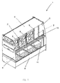
- Fig.1 is perspective view showing a tank architecture 1 according to the present disclosure, wherein the tank architecture 1 comprises two side panels 3, 4 arranged opposite to each other and upper and lower belts 5, 6 connected between the side panels 3, 4, which are used to form an accommodation space 2, that is to say, the side panels 3, 4 and the upper and lower belts 5, 6 conjunctly enclose the accommodation space 2.
- the upper belt 5 is connected together with the lower belt 6, and the accommodation space 2 is used for accommodating several functional units (not shown for the purpose of clarity); wherein the tank architecture 1 further comprises an internal stiffener assembly 7 and an external stiffener assembly 8 (see Fig.3 ); the internal stiffener assembly 7 is used for mounting the several functional units into the accommodation space 2, and the mounting positions of the several functional units can be arranged flexibly; the external stiffener assembly 8 is used for mounting several external mechanisms (not shown for the purpose of clarity), corresponding to the several functional units, outside the tank architecture 1.
- the skilled in this art may also arrange only one functional unit within the accommodation space.
- the internal stiffener assembly 7 comprises several inner stiffeners 9 mounted onto the inner side of the upper belt 5, the several inner stiffeners 9 being mounted equally spaced from each other.
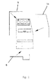
- the internal stiffener assembly 7 further comprises a rear beam 10, a cross beam 11 and several stiffener rods 12 for connecting the inner stiffeners 9 with the rear beams 10, the cross beam 11 and the rear beam 10 are arranged parallel with each other and conjunctly connected between the two side panels 3, 4, the cross beam 11 being used for assembling the rear panel 14 (see Fig.2 ) of the tank architecture, and the several stiffener rods 12 being provided to be parallel with and spaced apart from each other.
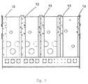
- the external stiffener assembly 8 comprises several outer stiffeners 13 in a shape of ⁇ profile in the cross section of the outer stiffener 13 perpendicular to its longitudinal direction, the outer stiffener being provided with several mounting holes (see Fig.5 ).
- the inner stiffener 9 and the outer stiffener 13 are used for tank reinforcement and mechanism fixation, so that, during the later stage of production, it is possible to provide different mounting holes for different functional units and thus to increase production efficiency and reduce processing time.
- the inner stiffener 9 is approximately in a shape of U profile in the cross section perpendicular to its longitudinal direction.
- the inner stiffener 9, the rear beam 10 and the cross beam 11 are also provided with several mounting holes respectively.
- the side panels and the upper and lower belts are sheet metals. These standardized sheet metals can be stacked together, thereby reducing space occupied, cost and time during transportation.
- the upper belt is provided with several sets of through holes, three of each set of through holes 14 being arranged in a triangular arrangement, inlay screw nut (not shown) and the through holes are utilized for the assembly of a fuse tube.
- a triangular arrangement may be used to reduce the width of a functional unit corresponding thereto so that its width is equivalent to that of other functional units.
- the use of inlay screw nut and through hole in a triangular arrangement may eliminate the use of welding studs, thus avoiding lower production efficiency caused by the difference among the positions of the welding studs.
- the essentially L-shaped upper belt 5 and the lower belt 6 essentially in a scoop shape are welded together, the inner stiffener 9 is connected to the inner side of the upper belt 5 through welding.
- Another embodiment according to the present disclosure provides a RMU comprising the above tank architecture.
- the present architecture may also retain the "nose" for Q functional units with higher voltage etc. so as to meet partial free combination of I and Q functional units.
- the width of the OCO CB functional units is reduced and its height is adjusted so that it can be consistent with other functional units.
- the present disclosure proposes outer stiffeners with ⁇ profile and inner stiffeners with U profile for reinforcing tank architecture and fixing mechanisms, so that, during the later stage of production, it is possible to provide different holes for different functional units and thus to increase production efficiency and depress processing time.
- the present disclosure also designs sheet metals (upper belt, lower belt, side panel and rear panel) which conjunctly compose the modular tank architecture. These standardized sheet metals can be stacked together, thereby reducing transportation expenses and time.
- the upper belt in the present disclosure has no welding stud so as to facilitate cutting holes during later stage.
- This inventive modular design could reduce the number of drawings, the types of the tank and data management cost, and also make the infrastructure design easier and improve the efficiency of technical maintenance. It is not required to design new tank architecture for a new requirement.
- This inventive modular structure comprises a cross beam, standard stiffener rod and stiffener in such a way that any functional units can be arranged arbitrarily at any position in the tank, thereby achieving the free combination of 1 to 6 functional units.
Landscapes
- Engineering & Computer Science (AREA)
- Power Engineering (AREA)
- Filling Or Discharging Of Gas Storage Vessels (AREA)
- Devices Affording Protection Of Roads Or Walls For Sound Insulation (AREA)
Applications Claiming Priority (1)
| Application Number | Priority Date | Filing Date | Title |
|---|---|---|---|
| CN201511021300.9A CN106936091A (zh) | 2015-12-30 | 2015-12-30 | 容纳功能单元的箱体结构和包括该箱体结构的二次环网柜 |
Publications (1)
| Publication Number | Publication Date |
|---|---|
| EP3188331A1 true EP3188331A1 (de) | 2017-07-05 |
Family
ID=55699580
Family Applications (1)
| Application Number | Title | Priority Date | Filing Date |
|---|---|---|---|
| EP16305328.3A Withdrawn EP3188331A1 (de) | 2015-12-30 | 2016-03-23 | Tankarchitektur für ringhaupteinheit |
Country Status (2)
| Country | Link |
|---|---|
| EP (1) | EP3188331A1 (de) |
| CN (1) | CN106936091A (de) |
Cited By (3)
| Publication number | Priority date | Publication date | Assignee | Title |
|---|---|---|---|---|
| FR3097383A1 (fr) * | 2019-06-13 | 2020-12-18 | Schneider Electric Industries Sas | cuve à intégrité mécanique renforcée |
| EP3975356A1 (de) * | 2020-09-28 | 2022-03-30 | Schneider Electric Industries SAS | Tank mit verstärkter mechanischer festigkeit |
| FR3118277A1 (fr) * | 2020-12-23 | 2022-06-24 | Schneider Electric Industries Sas | Cuve pour appareil électrique à moyenne tension |
Citations (4)
| Publication number | Priority date | Publication date | Assignee | Title |
|---|---|---|---|---|
| CN1089402A (zh) * | 1992-11-25 | 1994-07-13 | 株式会社明电舍 | 外壳内充以电气绝缘气体的绝缘开关装置 |
| US5715134A (en) * | 1995-10-26 | 1998-02-03 | Gec Alsthom T & D Sa | Screened medium-voltage substation |
| WO2010142302A1 (en) * | 2009-06-08 | 2010-12-16 | Abb Technology Ag | Metal encapsulation for switch gear, and method for manufacturing the same |
| US20150229109A1 (en) * | 2014-02-07 | 2015-08-13 | Abb Technology Ag | Medium voltage switchgear construction using symmetric sheet metal parts and panels to build compartment assemblies and subassemblies |
Family Cites Families (7)
| Publication number | Priority date | Publication date | Assignee | Title |
|---|---|---|---|---|
| CN201113291Y (zh) * | 2007-06-15 | 2008-09-10 | 北京电研华源电力技术有限公司 | 户外共箱式六氟化硫多回路环网柜 |
| CN203800594U (zh) * | 2013-08-28 | 2014-08-27 | 浙江亿德科技有限公司 | 机箱式抗谐波电容器 |
| CN203800385U (zh) * | 2014-05-13 | 2014-08-27 | 宁波南车城市轨道交通装备有限公司 | 超级电容柜 |
| CN203883337U (zh) * | 2014-05-15 | 2014-10-15 | 东北林业大学 | 组合式低压配电箱 |
| CN203895785U (zh) * | 2014-06-17 | 2014-10-22 | 上海伊田机电科技有限公司 | 组装功率柜 |
| CN204652838U (zh) * | 2015-05-14 | 2015-09-16 | 铁力山(北京)控制技术有限公司 | 一种强弱电走线分离式控制台 |
| CN204793761U (zh) * | 2015-07-28 | 2015-11-18 | 李丹丹 | 高效率风冷变电柜 |
-
2015
- 2015-12-30 CN CN201511021300.9A patent/CN106936091A/zh active Pending
-
2016
- 2016-03-23 EP EP16305328.3A patent/EP3188331A1/de not_active Withdrawn
Patent Citations (4)
| Publication number | Priority date | Publication date | Assignee | Title |
|---|---|---|---|---|
| CN1089402A (zh) * | 1992-11-25 | 1994-07-13 | 株式会社明电舍 | 外壳内充以电气绝缘气体的绝缘开关装置 |
| US5715134A (en) * | 1995-10-26 | 1998-02-03 | Gec Alsthom T & D Sa | Screened medium-voltage substation |
| WO2010142302A1 (en) * | 2009-06-08 | 2010-12-16 | Abb Technology Ag | Metal encapsulation for switch gear, and method for manufacturing the same |
| US20150229109A1 (en) * | 2014-02-07 | 2015-08-13 | Abb Technology Ag | Medium voltage switchgear construction using symmetric sheet metal parts and panels to build compartment assemblies and subassemblies |
Cited By (5)
| Publication number | Priority date | Publication date | Assignee | Title |
|---|---|---|---|---|
| FR3097383A1 (fr) * | 2019-06-13 | 2020-12-18 | Schneider Electric Industries Sas | cuve à intégrité mécanique renforcée |
| EP3975356A1 (de) * | 2020-09-28 | 2022-03-30 | Schneider Electric Industries SAS | Tank mit verstärkter mechanischer festigkeit |
| FR3118277A1 (fr) * | 2020-12-23 | 2022-06-24 | Schneider Electric Industries Sas | Cuve pour appareil électrique à moyenne tension |
| EP4020728A1 (de) * | 2020-12-23 | 2022-06-29 | Schneider Electric Industries SAS | Behälter für elektrisches mittelspannungsgerät |
| US11742640B2 (en) | 2020-12-23 | 2023-08-29 | Schneider Electric Industries Sas | Medium voltage electrical apparatus tank |
Also Published As
| Publication number | Publication date |
|---|---|
| CN106936091A (zh) | 2017-07-07 |
Similar Documents
| Publication | Publication Date | Title |
|---|---|---|
| DE102009037138B4 (de) | Batteriekasten | |
| EP3188331A1 (de) | Tankarchitektur für ringhaupteinheit | |
| DE102012005902B4 (de) | Hochspannungskabel-Führungsstruktur für ein elektrisch angetriebenes Fahrzeug | |
| US8628041B2 (en) | Method for realization of an aircraft structure and resulting structure | |
| DE102012224016A1 (de) | Stromzuführvorrichtung | |
| DE102009011524A1 (de) | Elektroenergie-Speicherzelle und Zellblock, Elektroenergie-Speichervorrichtung und Fahrzeug damit | |
| WO2016046146A1 (de) | Batteriegehäuse | |
| DE102012205021A1 (de) | Zellverbinder für ein Batteriesystem oder für eine Batteriezelle eines elektrischen Energiespeichers, Batterie und Kraftfahrzeug | |
| US20130164465A1 (en) | Anti lateral-torsional buckling structural member of an aircraft fuselage | |
| EP3242014B1 (de) | Gondelverkleidung für eine windenergieanlage | |
| DE112016004549T5 (de) | Stromspeichermodul | |
| DE102014205713A1 (de) | Energiespeichervorrichtung | |
| CN110615112A (zh) | 包括用于航空电子设备舱的横向框架的飞行器 | |
| DE102015000580B4 (de) | Elektrischer Energiespeicher und Kraftfahrzeug | |
| CN106494605A (zh) | 用于中央翼盒的一体式肋及其安装方法 | |
| US9848697B2 (en) | Modular aviation equipment rack | |
| EP4051579B1 (de) | Leichtbaustruktur für ein fahrzeug und luftfahrzeug | |
| EP2916368A1 (de) | Batteriepackung | |
| US10244660B2 (en) | Modular electronic assembly rack and modular electronic assembly comprising such a rack | |
| US20070139868A1 (en) | Electrical cabinet including a wiring support | |
| KR20190136101A (ko) | 축전지 유닛 | |
| EP3796414B1 (de) | Batteriemodul | |
| CN208746083U (zh) | 前副车架和车辆 | |
| US20040239215A1 (en) | Cabinet for electronic equipment | |
| DE112005003505T5 (de) | Einfach zu lagerndes, zu transportierendes und zu montierendes Gehäuse und dessen Verpackungsverfahren |
Legal Events
| Date | Code | Title | Description |
|---|---|---|---|
| PUAI | Public reference made under article 153(3) epc to a published international application that has entered the european phase |
Free format text: ORIGINAL CODE: 0009012 |
|
| STAA | Information on the status of an ep patent application or granted ep patent |
Free format text: STATUS: THE APPLICATION HAS BEEN PUBLISHED |
|
| AK | Designated contracting states |
Kind code of ref document: A1 Designated state(s): AL AT BE BG CH CY CZ DE DK EE ES FI FR GB GR HR HU IE IS IT LI LT LU LV MC MK MT NL NO PL PT RO RS SE SI SK SM TR |
|
| AX | Request for extension of the european patent |
Extension state: BA ME |
|
| STAA | Information on the status of an ep patent application or granted ep patent |
Free format text: STATUS: REQUEST FOR EXAMINATION WAS MADE |
|
| 17P | Request for examination filed |
Effective date: 20180103 |
|
| RBV | Designated contracting states (corrected) |
Designated state(s): AL AT BE BG CH CY CZ DE DK EE ES FI FR GB GR HR HU IE IS IT LI LT LU LV MC MK MT NL NO PL PT RO RS SE SI SK SM TR |
|
| STAA | Information on the status of an ep patent application or granted ep patent |
Free format text: STATUS: THE APPLICATION HAS BEEN WITHDRAWN |
|
| 18W | Application withdrawn |
Effective date: 20180327 |