EP3188317B1 - Contact électrique - Google Patents
Contact électrique Download PDFInfo
- Publication number
- EP3188317B1 EP3188317B1 EP15382667.2A EP15382667A EP3188317B1 EP 3188317 B1 EP3188317 B1 EP 3188317B1 EP 15382667 A EP15382667 A EP 15382667A EP 3188317 B1 EP3188317 B1 EP 3188317B1
- Authority
- EP
- European Patent Office
- Prior art keywords
- cutting
- electrical
- electrical contact
- base
- connection
- Prior art date
- Legal status (The legal status is an assumption and is not a legal conclusion. Google has not performed a legal analysis and makes no representation as to the accuracy of the status listed.)
- Active
Links
Images


Classifications
-
- H—ELECTRICITY
- H01—ELECTRIC ELEMENTS
- H01R—ELECTRICALLY-CONDUCTIVE CONNECTIONS; STRUCTURAL ASSOCIATIONS OF A PLURALITY OF MUTUALLY-INSULATED ELECTRICAL CONNECTING ELEMENTS; COUPLING DEVICES; CURRENT COLLECTORS
- H01R4/00—Electrically-conductive connections between two or more conductive members in direct contact, i.e. touching one another; Means for effecting or maintaining such contact; Electrically-conductive connections having two or more spaced connecting locations for conductors and using contact members penetrating insulation
- H01R4/24—Connections using contact members penetrating or cutting insulation or cable strands
- H01R4/2416—Connections using contact members penetrating or cutting insulation or cable strands the contact members having insulation-cutting edges, e.g. of tuning fork type
- H01R4/242—Connections using contact members penetrating or cutting insulation or cable strands the contact members having insulation-cutting edges, e.g. of tuning fork type the contact members being plates having a single slot
- H01R4/2437—Curved plates
- H01R4/2441—Curved plates tube-shaped
-
- H—ELECTRICITY
- H01—ELECTRIC ELEMENTS
- H01R—ELECTRICALLY-CONDUCTIVE CONNECTIONS; STRUCTURAL ASSOCIATIONS OF A PLURALITY OF MUTUALLY-INSULATED ELECTRICAL CONNECTING ELEMENTS; COUPLING DEVICES; CURRENT COLLECTORS
- H01R4/00—Electrically-conductive connections between two or more conductive members in direct contact, i.e. touching one another; Means for effecting or maintaining such contact; Electrically-conductive connections having two or more spaced connecting locations for conductors and using contact members penetrating insulation
- H01R4/24—Connections using contact members penetrating or cutting insulation or cable strands
- H01R4/2416—Connections using contact members penetrating or cutting insulation or cable strands the contact members having insulation-cutting edges, e.g. of tuning fork type
- H01R4/2445—Connections using contact members penetrating or cutting insulation or cable strands the contact members having insulation-cutting edges, e.g. of tuning fork type the contact members having additional means acting on the insulation or the wire, e.g. additional insulation penetrating means, strain relief means or wire cutting knives
Definitions
- the present invention relates to an electrical contact for electrical cables which allows the cover of the electrical cable to be cut more comfortably and with a reduced cutting path.
- Electrical cables comprise a nucleus formed by an electrical conductor, normally of copper or aluminum and an electrically insulated cover.
- an electrical device for example to a switch, a plug, etc. it is necessary to cut said cover and reach to the nucleus in order to be able to carry out the electrical connection with the electrical device.
- electrical contacts which comprise cutting and connection elements such that the cable is held and connected.
- the cable is introduced into the electrical contact in an initial position, where the cover of the cable is begun to be cut and the cable continues a path where the cover continues to be cut until it is completely cut, reaching the nucleus.
- the holding and connection of the conductor to an electrical device, for example to a switch or a plug, is enabled here.
- FR2921763 A1 discloses an insulation-displacement connection having at least one insulation-displacement element with a retaining slot, which cuts through an insulation of an electrical conductor with which electrical contact is to be made by the insulation-displacement element, in a sleeve body.
- DE1928058U discloses a connection terminal for wire conductors in switching and disconnecting strips of telecommunication, in particular telephone technology, which penetrate the insulation of the conductor during insertion.
- FR2819348 A1 discloses an interconnection unit having a cable selfstripping and connection element.
- DE19851956 A1 discloses a contact including two spring-like connecting legs, the free end sections of which are bent towards each other, defining a slit for holding an electrical wire.
- the connecting legs are formed as extensions to two opposing sidewalls of a main body with a closed polygonal wall crosssection.
- GB635943 A discloses a wire connected to a flat conductor by inserting it in a hole therein and pushing it, preferably by a tool, into a narrow slot of constant width extending from the hole.
- the electrical contact according to the present invention comprises a base and at least one cutting and connection element, the or each cutting and connection element defining an initial cutting edge and a cutting and connection portion and said initial cutting edge is closer to the base than said cutting and connection portion.
- each cutting and connection element comprises an arm and a cutting edge.
- the or each cutting and connection element is joined to the base by means of said arm, which, can advantageously be elastic owing to the material used in the construction thereof or owing to the design of the same such that the or each cutting and connection element can be moved slightly to be adapted to the cutting force exerted by the user or to avoid disconnections due to external agents such as vibrations.
- the process of cutting the cable is optimized, implementing greater force at the time where more force is needed, at the beginning in order to start to break the cover, and reducing the force to be exerted during the process of continuing to cut the cover.
- This decreasing force for cutting the cable allows, at the time of the connection, for there to be greater elasticity in the system and for the cutting path to be less than with the conventional connectors of this type.
- the force exerted by the contact on the nucleus of the conductor reduces, as a result, when there is a larger lever arm, the contact in the final position thereof works with a tension lower than the initial tension, at a much more elastic limit. In this way, small vibrations or pulls can be absorbed without altering the connection pressure between the contact and the nucleus of the conductor.
- the or each cutting and connection element define a plane which forms an acute angle with said base, that is to say, this plane defined by the pair of cutting and connection elements is oblique with respect to the base, allowing a tangential cut of the cover of the electrical cable.
- the or each cutting element defines a curve to consistently carry out the cut perpendicular to the axial direction of the cable, achieving a cleaner cut and with less distance.
- the initial cutting edge preferably comprises a mouth.
- each cutting and connection element can comprise a knurling which improves the adherence of the cover of the electrical cable with respect to the electrical contact itself, with the corresponding improvement in the action of cutting the cover.
- a contact which proceeds from a sheet which is initially folded over itself forming a U section where the base is the central part and each arm emerges from the same; with the particularity that on the end part of the arms, a second folding is carried out on each one, achieving an edge normal to the base and wherein the cutting and connection element is on normal edge which is also opposed to that of the other arm; in this way if the conductor to be connected is introduced from the part closest to the base and it is displaced in a direction opposed to the base, a contact with decreasing force is also provided.
- a "C” type electrical contact which principally works with bending forces
- it is a contact whose section has a similar shape to a “C” with the ends opposing, which, in the center of the section, is provided with the base and from which at both sides the arms emerge to be opposed at the end.
- Said arms are joined to a cutting and connection element by the edge thereof which is opposed to the other arm and this cutting and connection element, instead of having a parallel height to the base, is provided with a height oblique to the same so that in this way, the entry of the cable is provided in the part closest to the base and the cutting and connection is carried out in the direction opposed to the base, obtaining a system of decreasing force; being distinguished from the rest of the blades of the same type in that they are provided with both cutting and connection elements parallel to the base and thus working during the process with a constant force.
- a blade type electrical contact which principally works with torsion forces
- it is a flat contact, a sheet type, which at one of the ends thereof comprises a base which is joined to both arms which extend in the direction to the side opposed to the base and in that said arms are separated from each other by a groove passing from the base and wherein each arm is joined to a cutting and connection element and said cutting and connection elements are opposed on the faces with less thickness of the arms; it is distinguished from the rest of the blades of the prior art due to the fact that it is provided with a through hole in the area which separates the base from the two arms which carry out the mouth function of the conductor to be connected and with the cutting and connection process in the direction opposed to the base, achieving a decreasing force during said process; a process which is completely different to the one existing today since the entry of the cable is carried out from the end opposed to the base and the cutting and connection process is carried out in the direction to the base.
- said mouth is a hole for introducing the electrical cable to be connected.
- the electrical contact comprises a base (1) which is a substantially flat surface which serves to support the electrical contact.
- Said electrical contact also comprises two cutting and connection elements (2), although it could only comprises one cutting and connection element (2), which are placed substantially opposing each other as can be observed in the figures. If it is so desired, the interior edges of each pair of cutting and connection elements (2) can be slightly displaced with respect to each other, as is shown in figures 1 and 2 .
- the electrical contact comprises two arms (11) which extend from the base (1) defining a U shape and a cutting and connection element (2) extends from each arm (11) towards the interior of the electrical contact, preferably from the part furthest from the base (1) of each arm (11) and in a substantially perpendicular manner.
- these arms (11) preferably have an arched shape.
- Each cutting and connection element (2) defines an initial cutting edge (3) and a cutting and connection portion (4) such that the initial cutting edge (3) is arranged closer to the base than the cutting and connection portion (4), thereby providing a decreasing cutting force as has been previously described.
- the initial cutting edge (3) is the edge which first contacts the electrical cable (10) when the cutting of the cover of the cable is started, while the cutting and connection portion (4) is the portion where the electrical cable (10 is placed in the final connection position thereof as is shown in figure 2 .
- the initial cutting edge (3) is associated with a mouth (5) for the placement of the electrical cable (10).
- each cutting and connection element (2) also comprises a knurling which improves the adherence of the cover of the electrical cable with respect to the electrical contact itself with the corresponding improvement in the action of the cutting of the cover due to the fact that it is adhered to the contact and helps to break the possible plastic fibers of the cover of the electrical cable (10) better.
- the cutting and connection elements (2) in this example define a plane which forms an acute angle with the base (1), that is to say, said cutting and connection elements (2) are oblique with respect to the base (1), providing a short tangent.
- the base (1) is a substantially flat surface, which serves as a joining for the cutting and connection elements (2) by way of the arms (11) thereof.
- the cutting and connection elements (2) also comprise an initial cutting edge (3) and a cutting and connection portion (4), the initial cutting edge (3) being closer to the base than the cutting and connection portion (4).
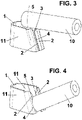
- the electrical contact for the electrical cables also comprises two arms (11) which extend from the base (1) defining a U shape, a cutting and connection element (2) extending from each arm towards the interior of the electrical contact in a substantially perpendicular manner, although in this case from the end of the arm (11) furthest from the base.
- the initial cutting edge (3) is also associated with a mouth (5) for the electrical cable (10). Also in this embodiment, the cutting of the cover of the electrical cable (10) is carried out, defining a rotational movement, as is indicated by means of the arrow of figure 3 .
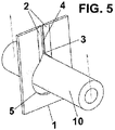
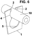
- the base (1) is an edge of the electrical contact and the principal different is that the electrical contact has a plate shape and the mouth (5) is a hole associated with the initial cutting edge (3).
- This hole is substantially circular and the diameter thereof is greater than the diameter of the electrical cable whose cover is desired to be cut.
- the displacement of the electrical cable (10) from the initial cutting edge (3) to the cutting and connection portion (4) is translational.
- the distance of the initial cutting edge (3) to the base (1) is less than the distance of the cutting and connection portion (4) to the base (1).
- the electrical contact of the present invention is the same in the three embodiments. Firstly, the electrical cable (10) should be placed facing the initial cutting edge (3), which is facilitated owing the mouth (5).
- the user displaces the electrical cable (10), initiating the cutting of the cover thereof on the initial cutting edge (3), a time at which the maximum force is applied.
- the electrical cable (10) continues being displaced towards the cutting and connection portion (4), but applying less force.
Landscapes
- Coupling Device And Connection With Printed Circuit (AREA)
- Multi-Conductor Connections (AREA)
- Processing Of Terminals (AREA)
- Connections Effected By Soldering, Adhesion, Or Permanent Deformation (AREA)
- Prostheses (AREA)
Claims (9)
- Contact électrique pour câbles électriques (10), qui comprend une base (1) et des éléments de coupe et de connexion (2), chaque élément de coupe et de connexion (2) définissant un bord de coupe initial (3) et une partie de coupe et de connexion (4), ledit bord de coupe initial (3) étant plus proche de la base (1) que ladite partie de coupe et de connexion (4), caractérisé en ce que le contact électrique comprend deux bras (11) s'étendant depuis la base (1) en définissant une forme en U, l'un des éléments de coupe et de connexion (2) s'étendant depuis chaque bras en direction de l'intérieur du contact électrique.
- Contact électrique pour câbles électriques selon la revendication 1, dans lequel chaque élément de coupe et de connexion (2) s'étend depuis la partie de chaque bras (11) la plus éloignée de la base (1).
- Contact électrique pour câbles électriques selon la revendication 1 ou 2, dans lequel chaque élément de coupe et de connexion (2) s'étend depuis chaque bras (11) de manière sensiblement perpendiculaire.
- Contact électrique pour câbles électriques selon la revendication 1, dans lequel chaque bras (11) présente une forme cintrée.
- Contact électrique pour câbles électriques selon la revendication 1, dans lequel chaque élément de coupe et de connexion (2) est disposé à l'extrémité de chaque bras (11) la plus éloignée de la base (1).
- Contact électrique pour câbles électriques selon la revendication 1, dans lequel le bord de coupe initial (3) comprend une gueule (5) pour le placement d'un câble électrique.
- Contact électrique pour câbles électriques selon la revendication 6, dans lequel la gueule (5) est un trou pour l'introduction du câble électrique.
- Contact électrique pour câbles électriques selon la revendication 1, dans lequel chaque élément de coupe et de connexion (2) définit un plan qui forme un angle aigu avec ladite base (1).
- Contact électrique pour câbles électriques selon la revendication 1, dans lequel la ou chaque paire d'éléments de coupe et de connexion (2) comprend un moletage.
Priority Applications (13)
| Application Number | Priority Date | Filing Date | Title |
|---|---|---|---|
| ES15382667T ES2913857T3 (es) | 2015-12-28 | 2015-12-28 | Contacto eléctrico |
| EP15382667.2A EP3188317B1 (fr) | 2015-12-28 | 2015-12-28 | Contact électrique |
| ARP160103810A AR106969A1 (es) | 2015-12-28 | 2016-12-13 | Contacto eléctrico |
| RU2018123363A RU2723347C2 (ru) | 2015-12-28 | 2016-12-19 | Электрический контакт |
| SG11201805555WA SG11201805555WA (en) | 2015-12-28 | 2016-12-19 | Electrical contact |
| AU2016383464A AU2016383464A1 (en) | 2015-12-28 | 2016-12-19 | Electrical contact |
| CN201680076373.4A CN108475854B (zh) | 2015-12-28 | 2016-12-19 | 电接触件 |
| BR112018013394-9A BR112018013394B1 (pt) | 2015-12-28 | 2016-12-19 | Contato elétrico para cabos elétricos |
| CA3010032A CA3010032A1 (fr) | 2015-12-28 | 2016-12-19 | Contact electrique |
| US16/066,937 US10276947B2 (en) | 2015-12-28 | 2016-12-19 | Electrical contact |
| MX2018007998A MX378518B (es) | 2015-12-28 | 2016-12-19 | Contacto electrico |
| PCT/EP2016/081716 WO2017114681A1 (fr) | 2015-12-28 | 2016-12-19 | Contact électrique |
| IL260322A IL260322A (en) | 2015-12-28 | 2018-06-28 | Electronic connector |
Applications Claiming Priority (1)
| Application Number | Priority Date | Filing Date | Title |
|---|---|---|---|
| EP15382667.2A EP3188317B1 (fr) | 2015-12-28 | 2015-12-28 | Contact électrique |
Publications (2)
| Publication Number | Publication Date |
|---|---|
| EP3188317A1 EP3188317A1 (fr) | 2017-07-05 |
| EP3188317B1 true EP3188317B1 (fr) | 2022-03-30 |
Family
ID=55527196
Family Applications (1)
| Application Number | Title | Priority Date | Filing Date |
|---|---|---|---|
| EP15382667.2A Active EP3188317B1 (fr) | 2015-12-28 | 2015-12-28 | Contact électrique |
Country Status (13)
| Country | Link |
|---|---|
| US (1) | US10276947B2 (fr) |
| EP (1) | EP3188317B1 (fr) |
| CN (1) | CN108475854B (fr) |
| AR (1) | AR106969A1 (fr) |
| AU (1) | AU2016383464A1 (fr) |
| BR (1) | BR112018013394B1 (fr) |
| CA (1) | CA3010032A1 (fr) |
| ES (1) | ES2913857T3 (fr) |
| IL (1) | IL260322A (fr) |
| MX (1) | MX378518B (fr) |
| RU (1) | RU2723347C2 (fr) |
| SG (1) | SG11201805555WA (fr) |
| WO (1) | WO2017114681A1 (fr) |
Citations (2)
| Publication number | Priority date | Publication date | Assignee | Title |
|---|---|---|---|---|
| GB635943A (en) * | 1946-10-11 | 1950-04-19 | Ericsson Telefon Ab L M | Improvements in or relating to methods of making electrical connections |
| DE19851956A1 (de) * | 1998-11-11 | 2000-06-08 | Gerd Conrad | Schneid-Klemmkontakt |
Family Cites Families (20)
| Publication number | Priority date | Publication date | Assignee | Title |
|---|---|---|---|---|
| US1847689A (en) * | 1929-02-02 | 1932-03-01 | Shakeproof Lock Washer Co | Electrical connecter |
| US1874593A (en) * | 1929-12-13 | 1932-08-30 | Shakeproof Lock Washer Co | Electrical connecter |
| DE1928058U (de) * | 1965-04-22 | 1965-12-02 | Siemens Ag | Loetfreie anschlussklemme. |
| AU5574573A (en) * | 1972-05-30 | 1974-11-21 | Amp Inc | Electrical contact elements and connectors electrical contact elements and connectors |
| SU1010681A1 (ru) * | 1981-11-05 | 1983-04-07 | Специализированное конструкторско-технологическое бюро строительной техники связи | Электрический соединитель |
| EP0106024A1 (fr) * | 1982-09-11 | 1984-04-25 | C.A. Weidmüller GmbH & Co. | Contact perçant l'isolation |
| US4983133A (en) * | 1989-05-31 | 1991-01-08 | Scyoc William C Van | Electrical terminal with annular section |
| DE9211819U1 (de) * | 1992-07-07 | 1993-11-04 | Grote & Hartmann | Elektrisches Kontaktelement |
| DE4403278C2 (de) * | 1994-01-31 | 1997-12-04 | Krone Ag | Schneidklemm-Kontaktelement |
| JP3225863B2 (ja) * | 1996-12-03 | 2001-11-05 | 住友電装株式会社 | 端子金具 |
| FR2764125A1 (fr) * | 1997-05-30 | 1998-12-04 | Entrelec Sa | Piece de connexion a fente pour agencement de raccordement pour au moins un fil electrique |
| JP4187338B2 (ja) * | 1999-03-01 | 2008-11-26 | モレックス インコーポレーテッド | 電気コネクタ |
| FR2810165B1 (fr) * | 2000-06-09 | 2006-10-06 | Entrelec Sa | Dispositif de connexion autodenudante pour un conducteur electrique gaine |
| FR2819348B1 (fr) * | 2001-01-05 | 2006-12-01 | Entrelec | Connexion autodenudante a fente convergente |
| RU35041U1 (ru) * | 2003-09-05 | 2003-12-20 | Закрытое Акционерное Общество "Связьстройдеталь" | Электрический соединитель |
| CN2735587Y (zh) * | 2004-08-17 | 2005-10-19 | 富士康(昆山)电脑接插件有限公司 | 电源连接器 |
| DE102007046616B4 (de) * | 2007-09-27 | 2011-04-14 | Wago Verwaltungsgesellschaft Mbh | Schneidklemmanschluss |
| DE202008007330U1 (de) * | 2008-06-02 | 2008-09-04 | Siemers, Rolf Friedhelm, Dipl.-Ing. | Schneidkontakt (IDC) mit einer Lack-Entfernungszone für die Kontaktierung von gelackten Massivleitern, z.B. Spulenenden |
| US8734191B2 (en) * | 2011-10-06 | 2014-05-27 | Tyco Electronics Corporation | Power connector system |
| CN102364753A (zh) * | 2011-11-24 | 2012-02-29 | 刘海涛 | 一种绝缘剥移连接端子 |
-
2015
- 2015-12-28 EP EP15382667.2A patent/EP3188317B1/fr active Active
- 2015-12-28 ES ES15382667T patent/ES2913857T3/es active Active
-
2016
- 2016-12-13 AR ARP160103810A patent/AR106969A1/es unknown
- 2016-12-19 WO PCT/EP2016/081716 patent/WO2017114681A1/fr not_active Ceased
- 2016-12-19 US US16/066,937 patent/US10276947B2/en not_active Expired - Fee Related
- 2016-12-19 SG SG11201805555WA patent/SG11201805555WA/en unknown
- 2016-12-19 MX MX2018007998A patent/MX378518B/es unknown
- 2016-12-19 AU AU2016383464A patent/AU2016383464A1/en not_active Abandoned
- 2016-12-19 BR BR112018013394-9A patent/BR112018013394B1/pt not_active IP Right Cessation
- 2016-12-19 CA CA3010032A patent/CA3010032A1/fr not_active Abandoned
- 2016-12-19 RU RU2018123363A patent/RU2723347C2/ru active
- 2016-12-19 CN CN201680076373.4A patent/CN108475854B/zh not_active Expired - Fee Related
-
2018
- 2018-06-28 IL IL260322A patent/IL260322A/en unknown
Patent Citations (2)
| Publication number | Priority date | Publication date | Assignee | Title |
|---|---|---|---|---|
| GB635943A (en) * | 1946-10-11 | 1950-04-19 | Ericsson Telefon Ab L M | Improvements in or relating to methods of making electrical connections |
| DE19851956A1 (de) * | 1998-11-11 | 2000-06-08 | Gerd Conrad | Schneid-Klemmkontakt |
Also Published As
| Publication number | Publication date |
|---|---|
| IL260322A (en) | 2018-08-30 |
| EP3188317A1 (fr) | 2017-07-05 |
| US20190020126A1 (en) | 2019-01-17 |
| AR106969A1 (es) | 2018-03-07 |
| CN108475854B (zh) | 2020-07-31 |
| RU2723347C2 (ru) | 2020-06-10 |
| ES2913857T3 (es) | 2022-06-06 |
| AU2016383464A1 (en) | 2018-07-19 |
| CA3010032A1 (fr) | 2017-07-06 |
| MX378518B (es) | 2025-03-11 |
| WO2017114681A1 (fr) | 2017-07-06 |
| RU2018123363A (ru) | 2020-01-30 |
| SG11201805555WA (en) | 2018-07-30 |
| BR112018013394A2 (pt) | 2018-12-04 |
| US10276947B2 (en) | 2019-04-30 |
| RU2018123363A3 (fr) | 2020-01-30 |
| CN108475854A (zh) | 2018-08-31 |
| BR112018013394B1 (pt) | 2022-12-20 |
Similar Documents
| Publication | Publication Date | Title |
|---|---|---|
| CA1077149A (fr) | Connecteur electrique a segments en pointe coupes par des fentes a percage d'isolant et a guidage de conducteur | |
| AU716555B2 (en) | Branching connector for an underground cable | |
| AU2012216570B2 (en) | Power Cable In-Line Power Outlet | |
| JP6512671B2 (ja) | 無剥離電線連結コネクタ用ターミナル | |
| HU196864B (en) | Cutting-clamping sleeve contact | |
| EP3075033B1 (fr) | Agencement pour un connecteur électrique | |
| KR19990008196A (ko) | 전기도체용 연결단자 | |
| US3594704A (en) | In-line connector for electrical conductors or the like | |
| EP3188317B1 (fr) | Contact électrique | |
| EP1615296A1 (fr) | Connecteur de dérivation compact | |
| CN102834976B (zh) | 具有用于切割电线的装置的连接端子 | |
| US9343826B2 (en) | Electrical contact | |
| HK1240712A1 (en) | Electrical contact | |
| HK1240712A (en) | Electrical contact | |
| EP4302365B1 (fr) | Connecteur cunéiforme perforant l'isolation | |
| EP1058345A1 (fr) | Connecteur de dérivation compact avec mise à la terre | |
| KR102956915B1 (ko) | 원터치 접속식 배선기구 | |
| US20060246767A1 (en) | Wire-terminal element | |
| JP7249157B2 (ja) | コネクタ端子 | |
| PL109589B1 (en) | Apparatus for manufacturing electric clamp connection,method of manufacturing electric clamp connection and electric clamp connection | |
| KR20250131056A (ko) | 원터치 접속식 배선기구 | |
| KR20220066456A (ko) | 전선이음 커넥터용 터미널 | |
| NO871272L (no) | Skjaereklemme for tilkobling av isolerte elektriske ledninger. |
Legal Events
| Date | Code | Title | Description |
|---|---|---|---|
| PUAI | Public reference made under article 153(3) epc to a published international application that has entered the european phase |
Free format text: ORIGINAL CODE: 0009012 |
|
| STAA | Information on the status of an ep patent application or granted ep patent |
Free format text: STATUS: THE APPLICATION HAS BEEN PUBLISHED |
|
| AK | Designated contracting states |
Kind code of ref document: A1 Designated state(s): AL AT BE BG CH CY CZ DE DK EE ES FI FR GB GR HR HU IE IS IT LI LT LU LV MC MK MT NL NO PL PT RO RS SE SI SK SM TR |
|
| AX | Request for extension of the european patent |
Extension state: BA ME |
|
| STAA | Information on the status of an ep patent application or granted ep patent |
Free format text: STATUS: REQUEST FOR EXAMINATION WAS MADE |
|
| 17P | Request for examination filed |
Effective date: 20180103 |
|
| RAV | Requested validation state of the european patent: fee paid |
Extension state: MD Effective date: 20180103 Extension state: MA Effective date: 20180103 |
|
| RAX | Requested extension states of the european patent have changed |
Extension state: BA Payment date: 20180103 Extension state: ME |
|
| RBV | Designated contracting states (corrected) |
Designated state(s): AL AT BE BG CH CY CZ DE DK EE ES FI FR GB GR HR HU IE IS IT LI LT LU LV MC MK MT NL NO PL PT RO RS SE SI SK SM TR |
|
| REG | Reference to a national code |
Ref country code: HK Ref legal event code: DE Ref document number: 1240712 Country of ref document: HK |
|
| STAA | Information on the status of an ep patent application or granted ep patent |
Free format text: STATUS: EXAMINATION IS IN PROGRESS |
|
| 17Q | First examination report despatched |
Effective date: 20190304 |
|
| REG | Reference to a national code |
Ref country code: DE Ref legal event code: R079 Ref document number: 602015077832 Country of ref document: DE Free format text: PREVIOUS MAIN CLASS: H01R0004240000 Ipc: H01R0004244100 |
|
| GRAP | Despatch of communication of intention to grant a patent |
Free format text: ORIGINAL CODE: EPIDOSNIGR1 |
|
| STAA | Information on the status of an ep patent application or granted ep patent |
Free format text: STATUS: GRANT OF PATENT IS INTENDED |
|
| RIC1 | Information provided on ipc code assigned before grant |
Ipc: H01R 4/2441 20180101AFI20211012BHEP |
|
| INTG | Intention to grant announced |
Effective date: 20211104 |
|
| GRAS | Grant fee paid |
Free format text: ORIGINAL CODE: EPIDOSNIGR3 |
|
| GRAA | (expected) grant |
Free format text: ORIGINAL CODE: 0009210 |
|
| STAA | Information on the status of an ep patent application or granted ep patent |
Free format text: STATUS: THE PATENT HAS BEEN GRANTED |
|
| AK | Designated contracting states |
Kind code of ref document: B1 Designated state(s): AL AT BE BG CH CY CZ DE DK EE ES FI FR GB GR HR HU IE IS IT LI LT LU LV MC MK MT NL NO PL PT RO RS SE SI SK SM TR |
|
| REG | Reference to a national code |
Ref country code: GB Ref legal event code: FG4D |
|
| REG | Reference to a national code |
Ref country code: CH Ref legal event code: EP |
|
| REG | Reference to a national code |
Ref country code: AT Ref legal event code: REF Ref document number: 1480045 Country of ref document: AT Kind code of ref document: T Effective date: 20220415 |
|
| REG | Reference to a national code |
Ref country code: DE Ref legal event code: R096 Ref document number: 602015077832 Country of ref document: DE |
|
| REG | Reference to a national code |
Ref country code: IE Ref legal event code: FG4D |
|
| REG | Reference to a national code |
Ref country code: ES Ref legal event code: FG2A Ref document number: 2913857 Country of ref document: ES Kind code of ref document: T3 Effective date: 20220606 |
|
| REG | Reference to a national code |
Ref country code: LT Ref legal event code: MG9D |
|
| PG25 | Lapsed in a contracting state [announced via postgrant information from national office to epo] |
Ref country code: SE Free format text: LAPSE BECAUSE OF FAILURE TO SUBMIT A TRANSLATION OF THE DESCRIPTION OR TO PAY THE FEE WITHIN THE PRESCRIBED TIME-LIMIT Effective date: 20220330 Ref country code: RS Free format text: LAPSE BECAUSE OF FAILURE TO SUBMIT A TRANSLATION OF THE DESCRIPTION OR TO PAY THE FEE WITHIN THE PRESCRIBED TIME-LIMIT Effective date: 20220330 Ref country code: NO Free format text: LAPSE BECAUSE OF FAILURE TO SUBMIT A TRANSLATION OF THE DESCRIPTION OR TO PAY THE FEE WITHIN THE PRESCRIBED TIME-LIMIT Effective date: 20220630 Ref country code: LT Free format text: LAPSE BECAUSE OF FAILURE TO SUBMIT A TRANSLATION OF THE DESCRIPTION OR TO PAY THE FEE WITHIN THE PRESCRIBED TIME-LIMIT Effective date: 20220330 Ref country code: HR Free format text: LAPSE BECAUSE OF FAILURE TO SUBMIT A TRANSLATION OF THE DESCRIPTION OR TO PAY THE FEE WITHIN THE PRESCRIBED TIME-LIMIT Effective date: 20220330 Ref country code: BG Free format text: LAPSE BECAUSE OF FAILURE TO SUBMIT A TRANSLATION OF THE DESCRIPTION OR TO PAY THE FEE WITHIN THE PRESCRIBED TIME-LIMIT Effective date: 20220630 |
|
| REG | Reference to a national code |
Ref country code: NL Ref legal event code: MP Effective date: 20220330 |
|
| REG | Reference to a national code |
Ref country code: AT Ref legal event code: MK05 Ref document number: 1480045 Country of ref document: AT Kind code of ref document: T Effective date: 20220330 |
|
| PG25 | Lapsed in a contracting state [announced via postgrant information from national office to epo] |
Ref country code: LV Free format text: LAPSE BECAUSE OF FAILURE TO SUBMIT A TRANSLATION OF THE DESCRIPTION OR TO PAY THE FEE WITHIN THE PRESCRIBED TIME-LIMIT Effective date: 20220330 Ref country code: GR Free format text: LAPSE BECAUSE OF FAILURE TO SUBMIT A TRANSLATION OF THE DESCRIPTION OR TO PAY THE FEE WITHIN THE PRESCRIBED TIME-LIMIT Effective date: 20220701 Ref country code: FI Free format text: LAPSE BECAUSE OF FAILURE TO SUBMIT A TRANSLATION OF THE DESCRIPTION OR TO PAY THE FEE WITHIN THE PRESCRIBED TIME-LIMIT Effective date: 20220330 |
|
| PG25 | Lapsed in a contracting state [announced via postgrant information from national office to epo] |
Ref country code: NL Free format text: LAPSE BECAUSE OF FAILURE TO SUBMIT A TRANSLATION OF THE DESCRIPTION OR TO PAY THE FEE WITHIN THE PRESCRIBED TIME-LIMIT Effective date: 20220330 |
|
| PG25 | Lapsed in a contracting state [announced via postgrant information from national office to epo] |
Ref country code: SM Free format text: LAPSE BECAUSE OF FAILURE TO SUBMIT A TRANSLATION OF THE DESCRIPTION OR TO PAY THE FEE WITHIN THE PRESCRIBED TIME-LIMIT Effective date: 20220330 Ref country code: SK Free format text: LAPSE BECAUSE OF FAILURE TO SUBMIT A TRANSLATION OF THE DESCRIPTION OR TO PAY THE FEE WITHIN THE PRESCRIBED TIME-LIMIT Effective date: 20220330 Ref country code: RO Free format text: LAPSE BECAUSE OF FAILURE TO SUBMIT A TRANSLATION OF THE DESCRIPTION OR TO PAY THE FEE WITHIN THE PRESCRIBED TIME-LIMIT Effective date: 20220330 Ref country code: PT Free format text: LAPSE BECAUSE OF FAILURE TO SUBMIT A TRANSLATION OF THE DESCRIPTION OR TO PAY THE FEE WITHIN THE PRESCRIBED TIME-LIMIT Effective date: 20220801 Ref country code: EE Free format text: LAPSE BECAUSE OF FAILURE TO SUBMIT A TRANSLATION OF THE DESCRIPTION OR TO PAY THE FEE WITHIN THE PRESCRIBED TIME-LIMIT Effective date: 20220330 Ref country code: CZ Free format text: LAPSE BECAUSE OF FAILURE TO SUBMIT A TRANSLATION OF THE DESCRIPTION OR TO PAY THE FEE WITHIN THE PRESCRIBED TIME-LIMIT Effective date: 20220330 Ref country code: AT Free format text: LAPSE BECAUSE OF FAILURE TO SUBMIT A TRANSLATION OF THE DESCRIPTION OR TO PAY THE FEE WITHIN THE PRESCRIBED TIME-LIMIT Effective date: 20220330 |
|
| VS25 | Lapsed in a validation state [announced via postgrant information from nat. office to epo] |
Ref country code: MD Free format text: LAPSE BECAUSE OF FAILURE TO SUBMIT A TRANSLATION OF THE DESCRIPTION OR TO PAY THE FEE WITHIN THE PRESCRIBED TIME-LIMIT Effective date: 20220330 |
|
| PG25 | Lapsed in a contracting state [announced via postgrant information from national office to epo] |
Ref country code: PL Free format text: LAPSE BECAUSE OF FAILURE TO SUBMIT A TRANSLATION OF THE DESCRIPTION OR TO PAY THE FEE WITHIN THE PRESCRIBED TIME-LIMIT Effective date: 20220330 Ref country code: IS Free format text: LAPSE BECAUSE OF FAILURE TO SUBMIT A TRANSLATION OF THE DESCRIPTION OR TO PAY THE FEE WITHIN THE PRESCRIBED TIME-LIMIT Effective date: 20220730 Ref country code: AL Free format text: LAPSE BECAUSE OF FAILURE TO SUBMIT A TRANSLATION OF THE DESCRIPTION OR TO PAY THE FEE WITHIN THE PRESCRIBED TIME-LIMIT Effective date: 20220330 |
|
| REG | Reference to a national code |
Ref country code: DE Ref legal event code: R097 Ref document number: 602015077832 Country of ref document: DE |
|
| PG25 | Lapsed in a contracting state [announced via postgrant information from national office to epo] |
Ref country code: DK Free format text: LAPSE BECAUSE OF FAILURE TO SUBMIT A TRANSLATION OF THE DESCRIPTION OR TO PAY THE FEE WITHIN THE PRESCRIBED TIME-LIMIT Effective date: 20220330 |
|
| PLBE | No opposition filed within time limit |
Free format text: ORIGINAL CODE: 0009261 |
|
| STAA | Information on the status of an ep patent application or granted ep patent |
Free format text: STATUS: NO OPPOSITION FILED WITHIN TIME LIMIT |
|
| 26N | No opposition filed |
Effective date: 20230103 |
|
| PG25 | Lapsed in a contracting state [announced via postgrant information from national office to epo] |
Ref country code: SI Free format text: LAPSE BECAUSE OF FAILURE TO SUBMIT A TRANSLATION OF THE DESCRIPTION OR TO PAY THE FEE WITHIN THE PRESCRIBED TIME-LIMIT Effective date: 20220330 |
|
| REG | Reference to a national code |
Ref country code: DE Ref legal event code: R119 Ref document number: 602015077832 Country of ref document: DE |
|
| PG25 | Lapsed in a contracting state [announced via postgrant information from national office to epo] |
Ref country code: IT Free format text: LAPSE BECAUSE OF FAILURE TO SUBMIT A TRANSLATION OF THE DESCRIPTION OR TO PAY THE FEE WITHIN THE PRESCRIBED TIME-LIMIT Effective date: 20220330 |
|
| REG | Reference to a national code |
Ref country code: CH Ref legal event code: PL |
|
| GBPC | Gb: european patent ceased through non-payment of renewal fee |
Effective date: 20221228 |
|
| REG | Reference to a national code |
Ref country code: BE Ref legal event code: MM Effective date: 20221231 |
|
| PG25 | Lapsed in a contracting state [announced via postgrant information from national office to epo] |
Ref country code: LU Free format text: LAPSE BECAUSE OF NON-PAYMENT OF DUE FEES Effective date: 20221228 |
|
| PG25 | Lapsed in a contracting state [announced via postgrant information from national office to epo] |
Ref country code: LI Free format text: LAPSE BECAUSE OF NON-PAYMENT OF DUE FEES Effective date: 20221231 Ref country code: IE Free format text: LAPSE BECAUSE OF NON-PAYMENT OF DUE FEES Effective date: 20221228 Ref country code: GB Free format text: LAPSE BECAUSE OF NON-PAYMENT OF DUE FEES Effective date: 20221228 Ref country code: DE Free format text: LAPSE BECAUSE OF NON-PAYMENT OF DUE FEES Effective date: 20230701 Ref country code: CH Free format text: LAPSE BECAUSE OF NON-PAYMENT OF DUE FEES Effective date: 20221231 |
|
| PG25 | Lapsed in a contracting state [announced via postgrant information from national office to epo] |
Ref country code: FR Free format text: LAPSE BECAUSE OF NON-PAYMENT OF DUE FEES Effective date: 20221231 Ref country code: BE Free format text: LAPSE BECAUSE OF NON-PAYMENT OF DUE FEES Effective date: 20221231 |
|
| PG25 | Lapsed in a contracting state [announced via postgrant information from national office to epo] |
Ref country code: HU Free format text: LAPSE BECAUSE OF FAILURE TO SUBMIT A TRANSLATION OF THE DESCRIPTION OR TO PAY THE FEE WITHIN THE PRESCRIBED TIME-LIMIT; INVALID AB INITIO Effective date: 20151228 |
|
| PG25 | Lapsed in a contracting state [announced via postgrant information from national office to epo] |
Ref country code: CY Free format text: LAPSE BECAUSE OF FAILURE TO SUBMIT A TRANSLATION OF THE DESCRIPTION OR TO PAY THE FEE WITHIN THE PRESCRIBED TIME-LIMIT Effective date: 20220330 |
|
| PG25 | Lapsed in a contracting state [announced via postgrant information from national office to epo] |
Ref country code: MK Free format text: LAPSE BECAUSE OF FAILURE TO SUBMIT A TRANSLATION OF THE DESCRIPTION OR TO PAY THE FEE WITHIN THE PRESCRIBED TIME-LIMIT Effective date: 20220330 |
|
| PG25 | Lapsed in a contracting state [announced via postgrant information from national office to epo] |
Ref country code: MC Free format text: LAPSE BECAUSE OF FAILURE TO SUBMIT A TRANSLATION OF THE DESCRIPTION OR TO PAY THE FEE WITHIN THE PRESCRIBED TIME-LIMIT Effective date: 20220330 |
|
| PG25 | Lapsed in a contracting state [announced via postgrant information from national office to epo] |
Ref country code: MC Free format text: LAPSE BECAUSE OF FAILURE TO SUBMIT A TRANSLATION OF THE DESCRIPTION OR TO PAY THE FEE WITHIN THE PRESCRIBED TIME-LIMIT Effective date: 20220330 |
|
| REG | Reference to a national code |
Ref country code: HK Ref legal event code: WD Ref document number: 1240712 Country of ref document: HK |
|
| PG25 | Lapsed in a contracting state [announced via postgrant information from national office to epo] |
Ref country code: MT Free format text: LAPSE BECAUSE OF FAILURE TO SUBMIT A TRANSLATION OF THE DESCRIPTION OR TO PAY THE FEE WITHIN THE PRESCRIBED TIME-LIMIT Effective date: 20220330 |
|
| VS25 | Lapsed in a validation state [announced via postgrant information from nat. office to epo] |
Ref country code: MA Free format text: FAILURE TO ELECT DOMICILE IN THE NATIONAL COUNTRY Effective date: 20220630 |
|
| PG25 | Lapsed in a contracting state [announced via postgrant information from national office to epo] |
Ref country code: TR Free format text: LAPSE BECAUSE OF FAILURE TO SUBMIT A TRANSLATION OF THE DESCRIPTION OR TO PAY THE FEE WITHIN THE PRESCRIBED TIME-LIMIT Effective date: 20220330 |
|
| PGFP | Annual fee paid to national office [announced via postgrant information from national office to epo] |
Ref country code: ES Payment date: 20260102 Year of fee payment: 11 |