EP3187647A1 - Haushaltsgerät mit elektronischer platine und verfahren zur herstellung eines haushaltsgeräts - Google Patents
Haushaltsgerät mit elektronischer platine und verfahren zur herstellung eines haushaltsgeräts Download PDFInfo
- Publication number
- EP3187647A1 EP3187647A1 EP15202987.2A EP15202987A EP3187647A1 EP 3187647 A1 EP3187647 A1 EP 3187647A1 EP 15202987 A EP15202987 A EP 15202987A EP 3187647 A1 EP3187647 A1 EP 3187647A1
- Authority
- EP
- European Patent Office
- Prior art keywords
- cover
- receptacle
- household appliance
- electronic board
- gasket
- Prior art date
- Legal status (The legal status is an assumption and is not a legal conclusion. Google has not performed a legal analysis and makes no representation as to the accuracy of the status listed.)
- Granted
Links
- 238000000034 method Methods 0.000 title claims description 11
- 238000004519 manufacturing process Methods 0.000 title claims description 5
- 238000007789 sealing Methods 0.000 claims abstract description 32
- 238000002347 injection Methods 0.000 claims description 15
- 239000007924 injection Substances 0.000 claims description 15
- 239000000463 material Substances 0.000 claims description 9
- 238000003780 insertion Methods 0.000 claims description 6
- 230000037431 insertion Effects 0.000 claims description 6
- 239000007788 liquid Substances 0.000 claims description 5
- 239000012778 molding material Substances 0.000 claims description 3
- 238000000465 moulding Methods 0.000 claims description 3
- 239000002245 particle Substances 0.000 description 13
- XLYOFNOQVPJJNP-UHFFFAOYSA-N water Substances O XLYOFNOQVPJJNP-UHFFFAOYSA-N 0.000 description 12
- 238000005406 washing Methods 0.000 description 9
- 230000007257 malfunction Effects 0.000 description 5
- 230000007547 defect Effects 0.000 description 4
- 239000011344 liquid material Substances 0.000 description 4
- 230000001066 destructive effect Effects 0.000 description 2
- 239000002360 explosive Substances 0.000 description 2
- 230000002093 peripheral effect Effects 0.000 description 2
- 239000006096 absorbing agent Substances 0.000 description 1
- 239000000654 additive Substances 0.000 description 1
- 238000013037 co-molding Methods 0.000 description 1
- 230000001419 dependent effect Effects 0.000 description 1
- 239000003599 detergent Substances 0.000 description 1
- 238000001035 drying Methods 0.000 description 1
- 230000000694 effects Effects 0.000 description 1
- 238000012986 modification Methods 0.000 description 1
- 230000004048 modification Effects 0.000 description 1
- 230000002035 prolonged effect Effects 0.000 description 1
- 230000035939 shock Effects 0.000 description 1
- 239000000243 solution Substances 0.000 description 1
- 230000006641 stabilisation Effects 0.000 description 1
- 238000011105 stabilization Methods 0.000 description 1
Images


Classifications
-
- D—TEXTILES; PAPER
- D06—TREATMENT OF TEXTILES OR THE LIKE; LAUNDERING; FLEXIBLE MATERIALS NOT OTHERWISE PROVIDED FOR
- D06F—LAUNDERING, DRYING, IRONING, PRESSING OR FOLDING TEXTILE ARTICLES
- D06F34/00—Details of control systems for washing machines, washer-dryers or laundry dryers
- D06F34/28—Arrangements for program selection, e.g. control panels therefor; Arrangements for indicating program parameters, e.g. the selected program or its progress
- D06F34/34—Arrangements for program selection, e.g. control panels therefor; Arrangements for indicating program parameters, e.g. the selected program or its progress characterised by mounting or attachment features, e.g. detachable control panels or detachable display panels
-
- D—TEXTILES; PAPER
- D06—TREATMENT OF TEXTILES OR THE LIKE; LAUNDERING; FLEXIBLE MATERIALS NOT OTHERWISE PROVIDED FOR
- D06F—LAUNDERING, DRYING, IRONING, PRESSING OR FOLDING TEXTILE ARTICLES
- D06F34/00—Details of control systems for washing machines, washer-dryers or laundry dryers
- D06F34/08—Control circuits or arrangements thereof
Definitions
- the invention generally relates to a household appliance.
- the invention more particularly relates to household appliance comprising an electronic board.
- the invention furthermore relates to a method for manufacturing a household appliance.
- Known household appliances such as laundry machines, i.e. washing machines, driers, and combined washer/driers, are usually provided with a user interface comprising a dashboard or control panel with input devices, knobs, buttons, etc., allowing the user to select or set washing and/or drying programs.
- the dashboards are typically provided also with output devices such as displays, LEDs, etc. for giving a feedback to the user related to the settings/status of the machine.
- An electronic board which can comprise controls to be operated on the user interface, is provided for, as way of example, receiving the user input, sending signals to a display to show information to the user on the current running or selected program and/or parameters thereof, and to operate valves for water supply or drain, to operate a motor for rotating a drum etc.
- the electronic board In order to ensure proper operation of the electronic board and to arrange it close to the user interface, it can be arranged in a receptacle which is then closed by a cover.
- the EP 2 876 196 A1 discloses a household appliance with a front panel, whereby on the rear side of the front panel a receptacle is arranged which receives an electronic board. A cover for closing the receptacle is not provided thus the electronic board can be subject to moist, steam, water or particles which can lead to malfunctioning of the electronic board.
- the aim of the invention is to provide a household appliance with at least one control circuit board comprising peripheral contacts that is easy to replace and reliably protected against moist and dirt.
- Another aim of the invention is to provide a household appliance which is easy to assemble and has an optimized reduced number of components.
- Another aim of the invention is to provide a method for assembling a household appliance.
- the invention in a first aspect, relates to a household appliance, comprising an electronic board and a receptacle which receives the electronic board, further comprising a cover for closing the receptacle, whereby the cover in an assembled state is connected to the receptacle, whereby fixing means are provided for a connection between the receptacle and the cover, and whereby a sealing element is provided for providing a sealed connection between said receptacle and said cover in an assembled state.
- the invention is based on the consideration that an electronic board, which is an essential component of the appliance, should be protected against moisture, steam, water and particles which could lead to a reduced functionality, malfunction or defect of the board.
- a protection can be achieved in a natural way by placing the electronic board in a box and by closing the box by a cover.
- Applicant has found that a reliable protection of the electronic board can be achieved by providing fixing means for connecting receptacle and cover and by providing a sealing element which seals the connection between receptacle and cover.
- the fixing means provide a removable connection between the receptacle and the cover. This allows an easy replacement of the electronic board in a convenient and a non-destructive way. In this way, malfunctions of the board due to humidity or contaminating are prevented in the first place. If, however, the board needs to be replaced, this can be performed in a convenient and non-destructive way.
- a sealed connection denotes especially a connection which seals against water/steam/humidity/contaminating particles as they occur within or in the periphery of a household appliance during operation.
- the receptacle is preferably built as a box and/or has essentially a box-like shape, especially at least one face wall and for orthogonal side walls.
- the sealing element is arranged on the receptacle.
- the sealing element is arranged on the cover.
- This configuration has advantages over the previous one during manufacturing, since the cover typically is a smaller component than the receptacle, the corresponding machine/mold for providing the sealing element on the cover can be dimensioned smaller.
- the sealing element preferably is a gasket which is co-molded to the cover. In this way, a robust and tight connection between gasket and cover can be achieved, yielding good sealing properties.
- the gasket is preferably made of rubber.
- the cover at its periphery advantageously comprises a groove, whereby the gasket is positioned at least partially inside the groove. In this way, a force fit and/or form-locking connection between gasket and cover is established. Additionally, the gasket is partly located inside the cover, allowing a compact design of the cover.
- the cover at its periphery comprises a frame from which two parallel shoulders protrude which form this groove between them, whereby the gasket is positioned at least partially inside the groove and covers at least one of these shoulders, whereby in the assembled state the gasket is arranged between at least one shoulder and a side surface of the receptacle, thereby sealing the connection between the receptacle and the cover.
- the cover preferably comprises a frontal side which in an assembled state faces the electronic board, and a back side opposed to said frontal side, and wherein on the cover on the frontal side gasket tracks are provided which in an assembled state face the electronic board.
- These tracks are preferably built as grooves or channels which during a molding process allow the liquid material to flow into regions where the gasket should be co-molded to the cover and possibly other parts of the cover where the material is needed.
- the cover preferably comprises a frontal side which in an assembled state faces the electronic board and a back side, wherein the cover on said frontal side comprises least one at least partially circumferential groove and an injection point for the molding material which is connected to at least one track through which material when injected in a liquid state in said injection point is allowed to flow.
- At least one connecting groove is advantageously provided from the injection point to the at least one at least partially circumferential groove, and whereby material when injected in a liquid state in the injection point is allowed to flow into the at least one at least partially circumferential groove.
- the cover comprises at least one hole for insertion of fixing means.
- fixing means are advantageously screws.
- the receptacle comprises at least one dome/protrusion for insertion of a screw, whereby the electronic board comprises at least one hole, and whereby the cover comprises at least one opening, whereby the dome, the hole and the opening are axially aligned in an assembled state so that a fixing element is lead through the opening, the hole and through the dome.
- the fixing element is preferably a screw. Alternatively, it can be a pin or snap means.
- the opening is preferably surrounded by a dome.
- a dome is provided on the cover with the opening inside.
- holes are provided on said cover in the domes. These holes preferably respectively comprise an inner thread which fits with a respective outer thread of the corresponding screw.
- the household appliance comprises a frontal plate or face plate, whereby a removable connection between the receptacle and the faceplate is provided.
- This connection is preferably achieved by a snap connection, whereby snap elements, especially snap teeth, are provided on receptacle and/or faceplate which engage with corresponding receiving elements on the other part.
- the frontal plate preferably comprises a front side and a rear side facing the interior of said household appliance and which in an assembled state faces the receptacle, whereby on the rear side at least one fixing means, especially for insertion of a screw, is provided.
- the face plate advantageously comprises a user interface.
- the user interface preferably comprises at least one user interface element with which the user can operate with the machine and preferably a least one display element and/or light element for indicating status information on the current status of the appliance.
- the electronic board preferably comprises a connector cage encompassing at least one contact, and whereby a connector sealing element is provided on the cover which at least partially in a sealing manner encompasses the connector cage.
- the connector sealing element is preferably a gasket which is co-molded to the cover.
- the connector sealing element advantageously comprises a frontal lip and a rear lip and two side lips, whereby the frontal and rear lips, respectively, have the length of corresponding sides of the connector cage.
- the length of the respective side lip thereby preferably equals to the length of the adjacent side of the connector cage.
- the length of the respective side lip exceeds the length of the adjacent side of the connector cage. This design allows using the same cover for electronic boards with different lengths of the connector cage.
- a removable connection is provided between the electronic board and the cover.
- the present invention relates to a method for manufacturing a household appliance, whereby the appliance comprises an electronic board, a receptacle, preferably a box, for receiving the electronic board and a cover for closing the receptacle, whereby the electronic board is placed inside the receptacle and the receptacle is closed by the cover, whereby before closing the receptacle by the cover, the cover is placed in a mold, and a gasket is co-molded on the cover in such a way that it provides a sealing connection between the receptacle and the cover in their assembled state.
- the cover comprises at least one at least partially circumferential groove and an injection point for the molding material, whereby at least one connecting track, especially a groove, is provided from the injection point to the at least one at least partially circumferential groove, and whereby material in a liquid state is injected in the injection point and allowed to flow into the at least one at least partially circumferential groove.
- This design of the cover allows the liquid material to flow from the injection point through the tracks and to reach all regions in which the gasket is to be formed, The gasket by this method is therefore actively formed.
- the cover preferably comprises at least one through-point, and whereby during molding, gasket material is allowed to flow into the through-point.
- the through-point is preferably a channel or opening in the cover.
- the invention relates also to a household appliance, comprising an electronic board and a receptacle which receives said electronic board, further comprising a cover for closing said receptacle, whereby said cover in an assembled state is connected to said receptacle, whereby fixing means are provided for a, especially removable, connection between the receptacle and the cover, whereby the electronic board comprises a connector cage encompassing at least one contact, and whereby a connector sealing element is provided on the cover which at least partially in a sealing manner encompasses the connector cage.
- the task solved by this appliance is to protect the electronic board with a connector cage from moist or dirt which could enter between cover and connector cage.
- the connector sealing element is preferably a gasket co-molded to the cover.
- the connector sealing element comprises a frontal lip and a rear lip and two side lips, whereby the frontal and rear lips have the length of corresponding sides of the connector cage.
- This configuration provides a tight sealing connection between the cover and the connector cage. While the contacts inside the connector cage remains accessible and can be connected by a connector and at the same time the space between electronic board and the receptacle opposite to the cover is at least partially sealed against steam or water or particles inside the appliance.
- the length of the respective side lip advantageously is equal to the length of the adjacent side of the connector cage. In this way, a sealed connection along the whole periphery of the connector cage is provided
- the length of said respective side lip exceeds the length of the adjacent side of said connector cage.
- the advantages of the invention are especially as follows.
- the sealing element simultaneously seals all important parts between the cover and the electronic board and thereby provides a reliable protection of the electronic board from steam, water or contaminating particles. In this way, the proper functioning of the appliance is enabled and the lifetimes of these electronic components and also of the whole appliance are prolonged.
- the combination of the electronic board, the box, the faceplate and the cover offers a great simplicity of the assembly. Only a few pieces are needed, and only few connection means are needed to firmly and securely connect these components.
- a laundry treatment appliance 2 which is built as a front-loading washing machine and comprises a housing or casing 6 with a preferable parallelepiped shape, the casing 6 comprising a front wall 10, two side walls 14, a cover plate 20 and a rear wall (not shown). Front wall 10 and side walls 14 are preferably part of a cabinet. A front door 24 is provided which can be opened for loading or unloading laundry through an opening into a washing drum.
- a washing tub is contained within casing 6, whereby a rotatable and perforated drum is contained by said washing tub.
- Both washing tub and drum have a substantially cylindrical shape.
- the tub is suspended in a floating manner inside casing 6 by means of a number of coil springs and shock absorbers.
- the drum is rotated by an electric motor (not shown), which transmits the rotating motion of a motor shaft to the drum by a belt/pulley system.
- the motor can be directly associated with the shaft of the drum.
- the tub is preferable connected to casing 6 by means of an elastic bellows or gasket.
- the laundry appliance can be a dryer (in which case the tub is not provided) or a combined washer and dryer.
- the preferred washing machine shown in FIG.1 on a front panel 48 comprises a drawer 30 with a front plate 34 and a handle 38 for pulling out and pushing back in drawer 30.
- Drawer 30 comprises at least one compartment for detergent or washing additives.
- Adjacent to drawer 30, a user interface 50 is provided.
- a switch 56 is provided for switching on/off appliance 2.
- user interface elements 60 such as, for example, touch buttons, light elements, display elements, are provided.
- FIG. 2 front panel 48, a box / receptacle 68, an electronic board 72 and a cover 78 are shown in an explosive view.
- Box 68 is a receptacle which in an assembled state receives electronic board 72.
- cover 78 is closing box 68.
- Box 68 comprises a front wall 80 which in the assembled state faces front panel 48 and four adjacent side walls 82, 84, 86, 88.
- Front panel 48 preferably comprises openings or holes or depressions 92 which in the assembled state receive protrusions 96 of box 68 which house touch contacts of touch sensors of touch switches which are arranged on board 72.
- Front panel 48 preferably comprises snap means 102 for attaching front panel 48 to the casing 6 of laundry treatment appliance 2.
- Snap means 106 are preferably provided on front panel 48 which engage with corresponding snap means 110 on box 68.
- domes 116 for insertion of fixing means which in the present preferred embodiment are screws
- these screws are preferably guided first through openings 120 in cover 78 and subsequently through openings 122 in board 72, which are built as domes with holes, and openings 130 of domes 126 on box 68.
- the screws then reach into domes 116 of front panel 48 which, respectively, comprise an inner thread into which the respective screw with an outer thread is screwed.
- the box 68 is preferably attached to front panel 48 by engaging of snap means 106 on front panel 48 with snap means 110 on box 68.
- the electronic board 72 is preferably attached to box 68 by snap means 76. Then the box 68 is closed by cover 78, thereby closing the internal space of box 68 in which electronic board 72 is arranged. Then, as the last assembly step, the same screws are then passed through these four components. Therefore, the same fixing means or connection means are used to for front panel 48, box 68, board 72 and cover 78, which yields an especially convenient and simple way to attach these components in a removable way.
- connection By the described connection between front panel 48, box 68 and cover 78, a connection is provided which only requires few and simple connection means and is removable.
- the electronic board 72 is housed in box 68 which is closed by cover 78. Since this connection is removable, the cover 78 is detachable from box 68 by loosening the above described screws; the electronic board 72 can easily be removed and repaired or replaced.
- Snap means 76 are preferably provided at the internal periphery of box 68 for engagement of box 68 with electronic board 72, thereby spatially fixing the electronic board 72 with respect to box 68.
- Board 72 preferably comprises a first group of contacts 136 which are located at the periphery of board 72. Board 72 preferably further comprises a connector cage 140 in which a second group of contacts is provided.
- FIG. 3 in a rear view, front panel 48, box 68, board 72 and cover 78 are shown in an assembled state in a rear view.
- Cover 78 of which a rear side 74 is shown comprises openings 120 which respectively receive screws.
- Cover 78 preferably comprises an opening 160 through which the contacts which are arranged within connector cage 140 are accessible.
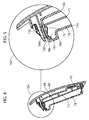
- FIG. 4 a section along line A-A of FIG. 3 is shown, and in FIG. 5 , an enlarged view of components drawn in a circle 164 in FIG 4 is shown.
- Snap means 76 are provided on cover 78 for the electronic board engagement and snap means 110 on frontal plate 48 are visible
- cover 78 The connection between cover 78 and box 68 is made in such a way that the electronic board 72 is at least partially protected from water, steam or contaminating particles which can be present in laundry treatment appliance 2.
- a sealing element which is preferably provided on cover 78 and which in the present preferred embodiment is a gasket 180 made preferably of rubber.
- Cover 78 preferably comprises at its periphery a frame 186 with two parallel shoulders 190, 192 which are perpendicular to a center plate 194 of cover 78 and between which a groove 196 is formed.
- shoulder 190 is an outer shoulder
- shoulder 192 is an inner shoulder and is located closer to a center of cover 78.
- Gasket 180 is preferably co-molded to cover 78 and is located within groove 196. Gasket 180 also covers shoulder 190. In the assembled state, the gasket 180 is in contact with box 68 and in this way acts as a sealing element. Groove 196 and gasket 180 are preferably arranged along the whole periphery of cover 78, thereby provided a fully sealed connection between box 68 and cover 78 and reliably preventing steam, water or particles to enter box 68 and to lead to malfunctions or defects of electronic board 72.
- gasket 180 is provided only partially along the periphery of cover 78, which means that not necessarily all sides of the periphery are provided with a gasket 180 and/or on one or more sides the gasket 180 is not provided over the whole length of the side.
- cover 78 and box 68 are built or designed in such a way that connecting parts without gasket 180 already provide reliable protection against steam, water or particles.
- pins 206, 208 are provided which in the assembled state reach through corresponding holes in board 72 and lead to further stabilization of the assembly.
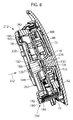
- FIG. 8 a cross section of front panel 48, box 68 and cover 78 is shown.
- outer shoulder 190 is preferably wider or broader than an opposing side 216.
- gasket tracks 220 are provided which are discussed below.
- a bore 226 or hole is provided on front panel 48 for inserting a screw. Bore 226 comprises an inner thread which engages with an outer thread of the screw.
- the screw is lead inserted in an insertion direction 232 through an opening in a dome 182 provided on cover 78 and subsequently through an opening in a dome 126 provided on box 68.
- a corresponding hole or opening 122 is provided on electronic board 72 through which the screw is lead.
- a light guide 300 is provided between electronic board 72 and box 68 for guiding light emitted from light elements provided on electronic board 72 to the front panel 48. These light elements on board 72 are preferably LEDS.
- FIG. 9 a rear side 256 of cover 78 is shown in an isomeric view and in FIG. 10 in a frontal view.
- rear side 256 is opposite to a front side of cover 78 which faces electronic board 72.
- ribs 258 are seen which are preferably behind the gasket tracks 220 on the front side of cover 78.
- Cover 78 comprises an opening 160 for a connector cage.
- FIG. 11 a cut through cover 78 along the line B-B shown in FIG. 10 is shown, of which a part encircled by a circle is shown in FIG. 12 .
- a through hole 228 reaching through to the groove 196 serves to improve the fixation of the gasket on the cover 78 by sticking to both components.
- the respective opening 120 is surrounded by a dome 182.
- a gasket 188 is provided on dome 182, on its side which in the assembled state faces electronic board 72. This gasket 188 provides a frontal sealing effect, preventing water, moisture or particles to pass between electronic board 72 and gasket 188.
- FIG. 14 the front side of cover 78 which in the assembled state faces electronic board 72 is shown in a perspective view. Gasket tracks 226 are shown which lead liquid material which is injected in an injection point 280.
- Opening 160 which in an assembled state allows access to the connector cage 140 is surrounded by a gasket 270 which seals the connection or interface region between gasket connector cage and cover 78.
- the opening 160 has preferably a rectangular shape.
- Gasket 270 is preferably formed with a frontal lip 271, a back lip 273 and two side lips 275, 277. The length or extension of all lips 271, 273, 275, 277 are dimensioned to provide a sealed connection to connector cage 140, preventing in the assembled state for moisture or particles to enter through gaps between gasket 270 and connector cage 140.
- the invention also concerns a cover 78 which comprises gasket 270 but without the peripheral gasket 180.
- the gasket 180 and preferably also the gasket 270 are produced in the same co-molding process in which liquid material is injected in at least one injection point 280 and is by running through gasket tracks 226 and is distributed in grooves to form the gaskets 180, 270.
- electronic board 72 in a first preferred embodiment is shown.
- several spring contacts 284 are provided which can be activated on the user interface provided on front panel 48.
- several light elements 324, 326 are provided which are preferably built as LEDs.
- a top frame 300 is shown which is mounted on board 72.
- Frame 300 is an additional component which preferably serves especially to house light guided in channels 330 which transmit light emitted from corresponding light elements on board 72 to the user interface.
- Frame 300 preferably comprises a display unit 320.
- Frame 300 and a board 72 in an assembled state are shown in FIG. 18 .
- the display unit 320 is illuminated by light elements 324 on electronic board 72.
- the display unit 320 is preferably used to indicate status information to the user, for instance the selected treatment program and/or parameters thereof and/or a corresponding status.
- An opening 340 allows the passage of dome 126 on box 68 during assembly.
- the household appliance 2 is according the invention manufactured as follows.
- the electronic board 72 is placed inside the box 68.
- the cover 78 is placed in a mold, and a gasket 180 is co-molded to cover 78 in such a way that a sealing connection between box 69 and cover 78 is achieved in the assembled state.
- the gasket 180 is preferably over-injected in cover 78.
- the box is closed by the cover 78.
- the at least one at least at least partially circumferential groove 196 is provided.
- the material to be co-molded in the liquid state then can flow from the injection point 280 into the groove 196, preferably by gasket tracks 220 or connecting tracks.
Landscapes
- Engineering & Computer Science (AREA)
- Textile Engineering (AREA)
- Casings For Electric Apparatus (AREA)
- Main Body Construction Of Washing Machines And Laundry Dryers (AREA)
- Detail Structures Of Washing Machines And Dryers (AREA)
Priority Applications (4)
| Application Number | Priority Date | Filing Date | Title |
|---|---|---|---|
| PL15202987T PL3187647T3 (pl) | 2015-12-29 | 2015-12-29 | Urządzenie gospodarstwa domowego z płytką elektroniczną i sposób wytwarzania urządzenia gospodarstwa domowego |
| EP15202987.2A EP3187647B1 (de) | 2015-12-29 | 2015-12-29 | Haushaltsgerät mit elektronischer platine und verfahren zur herstellung eines haushaltsgeräts |
| US16/064,080 US10954619B2 (en) | 2015-12-29 | 2016-12-07 | Household appliance with an electronic board and method for manufacturing a household appliance |
| PCT/EP2016/079977 WO2017114642A1 (en) | 2015-12-29 | 2016-12-07 | Household appliance with an electronic board and method for manufacturing a household appliance |
Applications Claiming Priority (1)
| Application Number | Priority Date | Filing Date | Title |
|---|---|---|---|
| EP15202987.2A EP3187647B1 (de) | 2015-12-29 | 2015-12-29 | Haushaltsgerät mit elektronischer platine und verfahren zur herstellung eines haushaltsgeräts |
Publications (2)
| Publication Number | Publication Date |
|---|---|
| EP3187647A1 true EP3187647A1 (de) | 2017-07-05 |
| EP3187647B1 EP3187647B1 (de) | 2022-02-23 |
Family
ID=55027538
Family Applications (1)
| Application Number | Title | Priority Date | Filing Date |
|---|---|---|---|
| EP15202987.2A Active EP3187647B1 (de) | 2015-12-29 | 2015-12-29 | Haushaltsgerät mit elektronischer platine und verfahren zur herstellung eines haushaltsgeräts |
Country Status (4)
| Country | Link |
|---|---|
| US (1) | US10954619B2 (de) |
| EP (1) | EP3187647B1 (de) |
| PL (1) | PL3187647T3 (de) |
| WO (1) | WO2017114642A1 (de) |
Cited By (3)
| Publication number | Priority date | Publication date | Assignee | Title |
|---|---|---|---|---|
| EP3741900A1 (de) * | 2019-05-23 | 2020-11-25 | BSH Hausgeräte GmbH | Bedienfeldkomponente für eine wäschebehandlungsmaschine und entsprechende wäschebehandlungsmaschine |
| EP4202102A4 (de) * | 2021-03-04 | 2024-03-13 | Samsung Electronics Co., Ltd. | Waschmaschine und wäschepflegevorrichtung |
| EP4394105A1 (de) * | 2022-12-30 | 2024-07-03 | Arçelik Anonim Sirketi | Haushaltsgerät mit einem plattenhalter und einer plattenhaltergruppe |
Families Citing this family (5)
| Publication number | Priority date | Publication date | Assignee | Title |
|---|---|---|---|---|
| CN111851003B (zh) * | 2019-04-28 | 2022-05-24 | 青岛海尔洗衣机有限公司 | 一种衣物处理设备的上盖及衣物处理设备 |
| CN112064296A (zh) * | 2019-05-23 | 2020-12-11 | 博西华电器(江苏)有限公司 | 衣物处理机器及其控制面板组件 |
| ES2974723T3 (es) * | 2019-09-17 | 2024-07-01 | Girbau Sa | Máquina lavadora con indicación de estado |
| TWI717172B (zh) * | 2019-12-26 | 2021-01-21 | 台灣松下電器股份有限公司 | 防水觸控面板裝置 |
| CN115772776A (zh) * | 2021-09-07 | 2023-03-10 | 青岛海尔洗衣机有限公司 | 衣物处理设备的盘座装置及衣物处理设备 |
Citations (6)
| Publication number | Priority date | Publication date | Assignee | Title |
|---|---|---|---|---|
| DE19651821A1 (de) * | 1996-12-13 | 1998-06-18 | Miele & Cie | Wäschebehandlungs- oder Geschirrspülmaschine |
| EP1176619A2 (de) * | 2000-07-27 | 2002-01-30 | Liebherr-Hausgeräte Gmbh | Elektronik-Bedieneinheit |
| DE20210707U1 (de) * | 2002-07-11 | 2003-11-20 | Diehl AKO Stiftung & Co. KG, 88239 Wangen | Hinterleuchtete Flüssigkristallanzeige, insbesondere zum Einsatz als Anzeigemodul hinter der Bedienblende eines Haushaltsgroßgerätes |
| EP1645679A2 (de) * | 2004-10-05 | 2006-04-12 | Miele & Cie. KG | Haushaltgerät, insbesondere Wäschebehandlungsmaschine, wie Waschmaschine, Waschtrockner oder Wäschetrockner mit einer Bedienblende |
| EP2458060A1 (de) * | 2010-11-29 | 2012-05-30 | Electrolux Home Products Corporation N.V. | Steuertafelanordnung für Haushaltanwendungen und Haushaltanwendung mit einer derartigen Steuertafelanordnung |
| EP2876196A1 (de) | 2013-11-21 | 2015-05-27 | Electrolux Appliances Aktiebolag | Haushaltsgerät mit einer Bedienblende |
Family Cites Families (15)
| Publication number | Priority date | Publication date | Assignee | Title |
|---|---|---|---|---|
| JP2875327B2 (ja) * | 1990-03-02 | 1999-03-31 | 株式会社日立製作所 | 液晶表示装置 |
| US5748270A (en) * | 1996-06-25 | 1998-05-05 | Ericsson, Inc. | LCD with electroluminescent backlighting |
| JP3919982B2 (ja) * | 1999-09-30 | 2007-05-30 | 株式会社日立製作所 | 液晶表示装置および液晶表示モニタ |
| KR100840235B1 (ko) * | 2001-08-29 | 2008-06-20 | 삼성전자주식회사 | 액정 표시 장치 |
| US7418838B2 (en) * | 2002-04-17 | 2008-09-02 | Lg Electronics Inc. | Washer |
| DE10344918B4 (de) * | 2003-09-17 | 2009-12-17 | Prettl Appliance Systems Gmbh | Blendenanordnung für eine Haushaltsmaschine |
| WO2007073105A1 (en) * | 2005-12-23 | 2007-06-28 | Lg Electronics Inc. | Laundry device |
| EP2380479A1 (de) * | 2010-04-23 | 2011-10-26 | Miele & Cie. KG | Bedieneinrichtung für Haushaltgeräte wie Herde, Dampfgarer, Wäschebehandlungs- oder Spülmaschinen. |
| EP2837726B1 (de) * | 2013-08-13 | 2016-10-12 | Electrolux Appliances Aktiebolag | Wäschebehandlungsvorrichtung mit einer Steuertafelanordnung |
| EP2837721B1 (de) * | 2013-08-13 | 2021-03-31 | Electrolux Appliances Aktiebolag | Waschmaschine mit einer Steuertafelanordnung |
| EP2837729B1 (de) * | 2013-08-13 | 2016-10-12 | Electrolux Appliances Aktiebolag | Wäschebehandlungsvorrichtung mit einer Steuertafelanordnung |
| US10367538B2 (en) * | 2014-04-11 | 2019-07-30 | Catalyst Lifestyle Limited | Waterproof case |
| KR102202721B1 (ko) * | 2015-02-25 | 2021-01-13 | 삼성전자주식회사 | 세탁기 |
| KR101708352B1 (ko) * | 2015-11-02 | 2017-02-20 | 엘지전자 주식회사 | 의류처리장치 |
| US10191519B2 (en) * | 2016-09-19 | 2019-01-29 | Google Llc | Electronic device with gasket sealing receptacle for tongue |
-
2015
- 2015-12-29 EP EP15202987.2A patent/EP3187647B1/de active Active
- 2015-12-29 PL PL15202987T patent/PL3187647T3/pl unknown
-
2016
- 2016-12-07 US US16/064,080 patent/US10954619B2/en active Active
- 2016-12-07 WO PCT/EP2016/079977 patent/WO2017114642A1/en active Application Filing
Patent Citations (6)
| Publication number | Priority date | Publication date | Assignee | Title |
|---|---|---|---|---|
| DE19651821A1 (de) * | 1996-12-13 | 1998-06-18 | Miele & Cie | Wäschebehandlungs- oder Geschirrspülmaschine |
| EP1176619A2 (de) * | 2000-07-27 | 2002-01-30 | Liebherr-Hausgeräte Gmbh | Elektronik-Bedieneinheit |
| DE20210707U1 (de) * | 2002-07-11 | 2003-11-20 | Diehl AKO Stiftung & Co. KG, 88239 Wangen | Hinterleuchtete Flüssigkristallanzeige, insbesondere zum Einsatz als Anzeigemodul hinter der Bedienblende eines Haushaltsgroßgerätes |
| EP1645679A2 (de) * | 2004-10-05 | 2006-04-12 | Miele & Cie. KG | Haushaltgerät, insbesondere Wäschebehandlungsmaschine, wie Waschmaschine, Waschtrockner oder Wäschetrockner mit einer Bedienblende |
| EP2458060A1 (de) * | 2010-11-29 | 2012-05-30 | Electrolux Home Products Corporation N.V. | Steuertafelanordnung für Haushaltanwendungen und Haushaltanwendung mit einer derartigen Steuertafelanordnung |
| EP2876196A1 (de) | 2013-11-21 | 2015-05-27 | Electrolux Appliances Aktiebolag | Haushaltsgerät mit einer Bedienblende |
Cited By (4)
| Publication number | Priority date | Publication date | Assignee | Title |
|---|---|---|---|---|
| EP3741900A1 (de) * | 2019-05-23 | 2020-11-25 | BSH Hausgeräte GmbH | Bedienfeldkomponente für eine wäschebehandlungsmaschine und entsprechende wäschebehandlungsmaschine |
| EP4202102A4 (de) * | 2021-03-04 | 2024-03-13 | Samsung Electronics Co., Ltd. | Waschmaschine und wäschepflegevorrichtung |
| US12012686B2 (en) | 2021-03-04 | 2024-06-18 | Samsung Electronics Co., Ltd. | Washing machine and clothes care apparatus |
| EP4394105A1 (de) * | 2022-12-30 | 2024-07-03 | Arçelik Anonim Sirketi | Haushaltsgerät mit einem plattenhalter und einer plattenhaltergruppe |
Also Published As
| Publication number | Publication date |
|---|---|
| US20190003103A1 (en) | 2019-01-03 |
| EP3187647B1 (de) | 2022-02-23 |
| WO2017114642A1 (en) | 2017-07-06 |
| US10954619B2 (en) | 2021-03-23 |
| PL3187647T3 (pl) | 2022-06-13 |
Similar Documents
| Publication | Publication Date | Title |
|---|---|---|
| US10954619B2 (en) | Household appliance with an electronic board and method for manufacturing a household appliance | |
| KR102627713B1 (ko) | 세탁기 | |
| EP2581025A1 (de) | Kontrolltafelbaugruppe und Waschmaschine damit | |
| US9988755B2 (en) | Household appliance | |
| US20170137991A1 (en) | Laundry Treatment Appliance | |
| EP2610389B1 (de) | Elektrisches Gerät mit Steuertafelanordnung | |
| US9903061B2 (en) | Laundry appliance provided with a control-panel assembly | |
| WO2016139136A1 (en) | Laundry treatment appliance with user interface | |
| WO2016139035A1 (en) | Laundry treatment appliance | |
| KR100484831B1 (ko) | 드럼세탁기의 세제통 장착구조 | |
| US11459693B2 (en) | Sensor module and laundry treating apparatus having the same | |
| EP3741900A1 (de) | Bedienfeldkomponente für eine wäschebehandlungsmaschine und entsprechende wäschebehandlungsmaschine | |
| AU2016258704B2 (en) | Household appliance with a control circuit board | |
| KR102204611B1 (ko) | 컨트롤패널 어셈블리 및 이를 포함하는 의류처리장치 | |
| KR20130026355A (ko) | 세탁기 | |
| JP7141988B2 (ja) | 洗濯乾燥機 | |
| US20240301612A1 (en) | Clothes treatment apparatus | |
| KR20060032060A (ko) | 드럼세탁기용 엘이디 가이드 마운팅 구조 | |
| KR20040011973A (ko) | 세탁기의 컨트롤패널과 기판 조립구조 |
Legal Events
| Date | Code | Title | Description |
|---|---|---|---|
| PUAI | Public reference made under article 153(3) epc to a published international application that has entered the european phase |
Free format text: ORIGINAL CODE: 0009012 |
|
| STAA | Information on the status of an ep patent application or granted ep patent |
Free format text: STATUS: THE APPLICATION HAS BEEN PUBLISHED |
|
| AK | Designated contracting states |
Kind code of ref document: A1 Designated state(s): AL AT BE BG CH CY CZ DE DK EE ES FI FR GB GR HR HU IE IS IT LI LT LU LV MC MK MT NL NO PL PT RO RS SE SI SK SM TR |
|
| AX | Request for extension of the european patent |
Extension state: BA ME |
|
| STAA | Information on the status of an ep patent application or granted ep patent |
Free format text: STATUS: REQUEST FOR EXAMINATION WAS MADE |
|
| 17P | Request for examination filed |
Effective date: 20180105 |
|
| RBV | Designated contracting states (corrected) |
Designated state(s): AL AT BE BG CH CY CZ DE DK EE ES FI FR GB GR HR HU IE IS IT LI LT LU LV MC MK MT NL NO PL PT RO RS SE SI SK SM TR |
|
| STAA | Information on the status of an ep patent application or granted ep patent |
Free format text: STATUS: EXAMINATION IS IN PROGRESS |
|
| 17Q | First examination report despatched |
Effective date: 20200626 |
|
| STAA | Information on the status of an ep patent application or granted ep patent |
Free format text: STATUS: EXAMINATION IS IN PROGRESS |
|
| REG | Reference to a national code |
Ref country code: DE Ref legal event code: R079 Ref document number: 602015077057 Country of ref document: DE Free format text: PREVIOUS MAIN CLASS: D06F0039000000 Ipc: D06F0034340000 |
|
| GRAP | Despatch of communication of intention to grant a patent |
Free format text: ORIGINAL CODE: EPIDOSNIGR1 |
|
| STAA | Information on the status of an ep patent application or granted ep patent |
Free format text: STATUS: GRANT OF PATENT IS INTENDED |
|
| RIC1 | Information provided on ipc code assigned before grant |
Ipc: D06F 34/34 20200101AFI20211015BHEP |
|
| INTG | Intention to grant announced |
Effective date: 20211110 |
|
| RIN1 | Information on inventor provided before grant (corrected) |
Inventor name: DE PELLEGRIN, ANDREA |
|
| GRAS | Grant fee paid |
Free format text: ORIGINAL CODE: EPIDOSNIGR3 |
|
| GRAA | (expected) grant |
Free format text: ORIGINAL CODE: 0009210 |
|
| STAA | Information on the status of an ep patent application or granted ep patent |
Free format text: STATUS: THE PATENT HAS BEEN GRANTED |
|
| AK | Designated contracting states |
Kind code of ref document: B1 Designated state(s): AL AT BE BG CH CY CZ DE DK EE ES FI FR GB GR HR HU IE IS IT LI LT LU LV MC MK MT NL NO PL PT RO RS SE SI SK SM TR |
|
| REG | Reference to a national code |
Ref country code: GB Ref legal event code: FG4D |
|
| REG | Reference to a national code |
Ref country code: CH Ref legal event code: EP |
|
| REG | Reference to a national code |
Ref country code: DE Ref legal event code: R096 Ref document number: 602015077057 Country of ref document: DE |
|
| REG | Reference to a national code |
Ref country code: AT Ref legal event code: REF Ref document number: 1470549 Country of ref document: AT Kind code of ref document: T Effective date: 20220315 |
|
| REG | Reference to a national code |
Ref country code: IE Ref legal event code: FG4D |
|
| REG | Reference to a national code |
Ref country code: LT Ref legal event code: MG9D |
|
| REG | Reference to a national code |
Ref country code: NL Ref legal event code: MP Effective date: 20220223 |
|
| REG | Reference to a national code |
Ref country code: AT Ref legal event code: MK05 Ref document number: 1470549 Country of ref document: AT Kind code of ref document: T Effective date: 20220223 |
|
| PG25 | Lapsed in a contracting state [announced via postgrant information from national office to epo] |
Ref country code: SE Free format text: LAPSE BECAUSE OF FAILURE TO SUBMIT A TRANSLATION OF THE DESCRIPTION OR TO PAY THE FEE WITHIN THE PRESCRIBED TIME-LIMIT Effective date: 20220223 Ref country code: RS Free format text: LAPSE BECAUSE OF FAILURE TO SUBMIT A TRANSLATION OF THE DESCRIPTION OR TO PAY THE FEE WITHIN THE PRESCRIBED TIME-LIMIT Effective date: 20220223 Ref country code: PT Free format text: LAPSE BECAUSE OF FAILURE TO SUBMIT A TRANSLATION OF THE DESCRIPTION OR TO PAY THE FEE WITHIN THE PRESCRIBED TIME-LIMIT Effective date: 20220623 Ref country code: NO Free format text: LAPSE BECAUSE OF FAILURE TO SUBMIT A TRANSLATION OF THE DESCRIPTION OR TO PAY THE FEE WITHIN THE PRESCRIBED TIME-LIMIT Effective date: 20220523 Ref country code: NL Free format text: LAPSE BECAUSE OF FAILURE TO SUBMIT A TRANSLATION OF THE DESCRIPTION OR TO PAY THE FEE WITHIN THE PRESCRIBED TIME-LIMIT Effective date: 20220223 Ref country code: LT Free format text: LAPSE BECAUSE OF FAILURE TO SUBMIT A TRANSLATION OF THE DESCRIPTION OR TO PAY THE FEE WITHIN THE PRESCRIBED TIME-LIMIT Effective date: 20220223 Ref country code: HR Free format text: LAPSE BECAUSE OF FAILURE TO SUBMIT A TRANSLATION OF THE DESCRIPTION OR TO PAY THE FEE WITHIN THE PRESCRIBED TIME-LIMIT Effective date: 20220223 Ref country code: ES Free format text: LAPSE BECAUSE OF FAILURE TO SUBMIT A TRANSLATION OF THE DESCRIPTION OR TO PAY THE FEE WITHIN THE PRESCRIBED TIME-LIMIT Effective date: 20220223 Ref country code: BG Free format text: LAPSE BECAUSE OF FAILURE TO SUBMIT A TRANSLATION OF THE DESCRIPTION OR TO PAY THE FEE WITHIN THE PRESCRIBED TIME-LIMIT Effective date: 20220523 |
|
| PG25 | Lapsed in a contracting state [announced via postgrant information from national office to epo] |
Ref country code: LV Free format text: LAPSE BECAUSE OF FAILURE TO SUBMIT A TRANSLATION OF THE DESCRIPTION OR TO PAY THE FEE WITHIN THE PRESCRIBED TIME-LIMIT Effective date: 20220223 Ref country code: GR Free format text: LAPSE BECAUSE OF FAILURE TO SUBMIT A TRANSLATION OF THE DESCRIPTION OR TO PAY THE FEE WITHIN THE PRESCRIBED TIME-LIMIT Effective date: 20220524 Ref country code: FI Free format text: LAPSE BECAUSE OF FAILURE TO SUBMIT A TRANSLATION OF THE DESCRIPTION OR TO PAY THE FEE WITHIN THE PRESCRIBED TIME-LIMIT Effective date: 20220223 Ref country code: AT Free format text: LAPSE BECAUSE OF FAILURE TO SUBMIT A TRANSLATION OF THE DESCRIPTION OR TO PAY THE FEE WITHIN THE PRESCRIBED TIME-LIMIT Effective date: 20220223 |
|
| PG25 | Lapsed in a contracting state [announced via postgrant information from national office to epo] |
Ref country code: IS Free format text: LAPSE BECAUSE OF FAILURE TO SUBMIT A TRANSLATION OF THE DESCRIPTION OR TO PAY THE FEE WITHIN THE PRESCRIBED TIME-LIMIT Effective date: 20220623 |
|
| PG25 | Lapsed in a contracting state [announced via postgrant information from national office to epo] |
Ref country code: SM Free format text: LAPSE BECAUSE OF FAILURE TO SUBMIT A TRANSLATION OF THE DESCRIPTION OR TO PAY THE FEE WITHIN THE PRESCRIBED TIME-LIMIT Effective date: 20220223 Ref country code: SK Free format text: LAPSE BECAUSE OF FAILURE TO SUBMIT A TRANSLATION OF THE DESCRIPTION OR TO PAY THE FEE WITHIN THE PRESCRIBED TIME-LIMIT Effective date: 20220223 Ref country code: RO Free format text: LAPSE BECAUSE OF FAILURE TO SUBMIT A TRANSLATION OF THE DESCRIPTION OR TO PAY THE FEE WITHIN THE PRESCRIBED TIME-LIMIT Effective date: 20220223 Ref country code: EE Free format text: LAPSE BECAUSE OF FAILURE TO SUBMIT A TRANSLATION OF THE DESCRIPTION OR TO PAY THE FEE WITHIN THE PRESCRIBED TIME-LIMIT Effective date: 20220223 Ref country code: DK Free format text: LAPSE BECAUSE OF FAILURE TO SUBMIT A TRANSLATION OF THE DESCRIPTION OR TO PAY THE FEE WITHIN THE PRESCRIBED TIME-LIMIT Effective date: 20220223 Ref country code: CZ Free format text: LAPSE BECAUSE OF FAILURE TO SUBMIT A TRANSLATION OF THE DESCRIPTION OR TO PAY THE FEE WITHIN THE PRESCRIBED TIME-LIMIT Effective date: 20220223 |
|
| REG | Reference to a national code |
Ref country code: DE Ref legal event code: R097 Ref document number: 602015077057 Country of ref document: DE |
|
| PG25 | Lapsed in a contracting state [announced via postgrant information from national office to epo] |
Ref country code: AL Free format text: LAPSE BECAUSE OF FAILURE TO SUBMIT A TRANSLATION OF THE DESCRIPTION OR TO PAY THE FEE WITHIN THE PRESCRIBED TIME-LIMIT Effective date: 20220223 |
|
| PLBE | No opposition filed within time limit |
Free format text: ORIGINAL CODE: 0009261 |
|
| STAA | Information on the status of an ep patent application or granted ep patent |
Free format text: STATUS: NO OPPOSITION FILED WITHIN TIME LIMIT |
|
| 26N | No opposition filed |
Effective date: 20221124 |
|
| PG25 | Lapsed in a contracting state [announced via postgrant information from national office to epo] |
Ref country code: SI Free format text: LAPSE BECAUSE OF FAILURE TO SUBMIT A TRANSLATION OF THE DESCRIPTION OR TO PAY THE FEE WITHIN THE PRESCRIBED TIME-LIMIT Effective date: 20220223 |
|
| REG | Reference to a national code |
Ref country code: CH Ref legal event code: PL |
|
| P01 | Opt-out of the competence of the unified patent court (upc) registered |
Effective date: 20230625 |
|
| GBPC | Gb: european patent ceased through non-payment of renewal fee |
Effective date: 20221229 |
|
| REG | Reference to a national code |
Ref country code: BE Ref legal event code: MM Effective date: 20221231 |
|
| PG25 | Lapsed in a contracting state [announced via postgrant information from national office to epo] |
Ref country code: LU Free format text: LAPSE BECAUSE OF NON-PAYMENT OF DUE FEES Effective date: 20221229 |
|
| PG25 | Lapsed in a contracting state [announced via postgrant information from national office to epo] |
Ref country code: LI Free format text: LAPSE BECAUSE OF NON-PAYMENT OF DUE FEES Effective date: 20221231 Ref country code: IE Free format text: LAPSE BECAUSE OF NON-PAYMENT OF DUE FEES Effective date: 20221229 Ref country code: GB Free format text: LAPSE BECAUSE OF NON-PAYMENT OF DUE FEES Effective date: 20221229 Ref country code: CH Free format text: LAPSE BECAUSE OF NON-PAYMENT OF DUE FEES Effective date: 20221231 |
|
| PG25 | Lapsed in a contracting state [announced via postgrant information from national office to epo] |
Ref country code: FR Free format text: LAPSE BECAUSE OF NON-PAYMENT OF DUE FEES Effective date: 20221231 Ref country code: BE Free format text: LAPSE BECAUSE OF NON-PAYMENT OF DUE FEES Effective date: 20221231 |
|
| PGFP | Annual fee paid to national office [announced via postgrant information from national office to epo] |
Ref country code: IT Payment date: 20231221 Year of fee payment: 9 |
|
| PGFP | Annual fee paid to national office [announced via postgrant information from national office to epo] |
Ref country code: PL Payment date: 20231218 Year of fee payment: 9 |
|
| PG25 | Lapsed in a contracting state [announced via postgrant information from national office to epo] |
Ref country code: HU Free format text: LAPSE BECAUSE OF FAILURE TO SUBMIT A TRANSLATION OF THE DESCRIPTION OR TO PAY THE FEE WITHIN THE PRESCRIBED TIME-LIMIT; INVALID AB INITIO Effective date: 20151229 |
|
| PG25 | Lapsed in a contracting state [announced via postgrant information from national office to epo] |
Ref country code: CY Free format text: LAPSE BECAUSE OF FAILURE TO SUBMIT A TRANSLATION OF THE DESCRIPTION OR TO PAY THE FEE WITHIN THE PRESCRIBED TIME-LIMIT Effective date: 20220223 |
|
| PGFP | Annual fee paid to national office [announced via postgrant information from national office to epo] |
Ref country code: DE Payment date: 20231227 Year of fee payment: 9 |
|
| PG25 | Lapsed in a contracting state [announced via postgrant information from national office to epo] |
Ref country code: MK Free format text: LAPSE BECAUSE OF FAILURE TO SUBMIT A TRANSLATION OF THE DESCRIPTION OR TO PAY THE FEE WITHIN THE PRESCRIBED TIME-LIMIT Effective date: 20220223 |
|
| PG25 | Lapsed in a contracting state [announced via postgrant information from national office to epo] |
Ref country code: MC Free format text: LAPSE BECAUSE OF FAILURE TO SUBMIT A TRANSLATION OF THE DESCRIPTION OR TO PAY THE FEE WITHIN THE PRESCRIBED TIME-LIMIT Effective date: 20220223 |
|
| PG25 | Lapsed in a contracting state [announced via postgrant information from national office to epo] |
Ref country code: MC Free format text: LAPSE BECAUSE OF FAILURE TO SUBMIT A TRANSLATION OF THE DESCRIPTION OR TO PAY THE FEE WITHIN THE PRESCRIBED TIME-LIMIT Effective date: 20220223 |
|
| PG25 | Lapsed in a contracting state [announced via postgrant information from national office to epo] |
Ref country code: MT Free format text: LAPSE BECAUSE OF FAILURE TO SUBMIT A TRANSLATION OF THE DESCRIPTION OR TO PAY THE FEE WITHIN THE PRESCRIBED TIME-LIMIT Effective date: 20220223 |