EP3187427B2 - Device and method for grabbing and transporting rsc packs - Google Patents
Device and method for grabbing and transporting rsc packs Download PDFInfo
- Publication number
- EP3187427B2 EP3187427B2 EP16199590.7A EP16199590A EP3187427B2 EP 3187427 B2 EP3187427 B2 EP 3187427B2 EP 16199590 A EP16199590 A EP 16199590A EP 3187427 B2 EP3187427 B2 EP 3187427B2
- Authority
- EP
- European Patent Office
- Prior art keywords
- cardboard
- gripping
- transversal
- gripping elements
- sleeve
- Prior art date
- Legal status (The legal status is an assumption and is not a legal conclusion. Google has not performed a legal analysis and makes no representation as to the accuracy of the status listed.)
- Active
Links
- 238000000034 method Methods 0.000 title description 9
- 239000003292 glue Substances 0.000 claims description 6
- 230000001360 synchronised effect Effects 0.000 claims 1
- 238000006073 displacement reaction Methods 0.000 description 8
- 239000000853 adhesive Substances 0.000 description 6
- 230000001070 adhesive effect Effects 0.000 description 6
- 238000003032 molecular docking Methods 0.000 description 5
- 238000004026 adhesive bonding Methods 0.000 description 4
- 239000000463 material Substances 0.000 description 4
- AZUYLZMQTIKGSC-UHFFFAOYSA-N 1-[6-[4-(5-chloro-6-methyl-1H-indazol-4-yl)-5-methyl-3-(1-methylindazol-5-yl)pyrazol-1-yl]-2-azaspiro[3.3]heptan-2-yl]prop-2-en-1-one Chemical compound ClC=1C(=C2C=NNC2=CC=1C)C=1C(=NN(C=1C)C1CC2(CN(C2)C(C=C)=O)C1)C=1C=C2C=NN(C2=CC=1)C AZUYLZMQTIKGSC-UHFFFAOYSA-N 0.000 description 2
- 230000004323 axial length Effects 0.000 description 2
- 238000004519 manufacturing process Methods 0.000 description 2
- 230000002093 peripheral effect Effects 0.000 description 2
- 230000001105 regulatory effect Effects 0.000 description 2
- 230000000284 resting effect Effects 0.000 description 2
- 208000031872 Body Remains Diseases 0.000 description 1
- 241001295925 Gegenes Species 0.000 description 1
- 241000124008 Mammalia Species 0.000 description 1
- 238000010276 construction Methods 0.000 description 1
- 230000001419 dependent effect Effects 0.000 description 1
- 230000000694 effects Effects 0.000 description 1
- 230000002996 emotional effect Effects 0.000 description 1
- 238000007654 immersion Methods 0.000 description 1
- 238000003825 pressing Methods 0.000 description 1
- 238000007493 shaping process Methods 0.000 description 1
- 238000003860 storage Methods 0.000 description 1
- 239000004753 textile Substances 0.000 description 1
- 238000011144 upstream manufacturing Methods 0.000 description 1
Images


Classifications
-
- B—PERFORMING OPERATIONS; TRANSPORTING
- B65—CONVEYING; PACKING; STORING; HANDLING THIN OR FILAMENTARY MATERIAL
- B65B—MACHINES, APPARATUS OR DEVICES FOR, OR METHODS OF, PACKAGING ARTICLES OR MATERIALS; UNPACKING
- B65B43/00—Forming, feeding, opening or setting-up containers or receptacles in association with packaging
- B65B43/26—Opening or distending bags; Opening, erecting, or setting-up boxes, cartons, or carton blanks
- B65B43/34—Opening or distending bags; Opening, erecting, or setting-up boxes, cartons, or carton blanks by internal pressure
- B65B43/345—Opening or distending bags; Opening, erecting, or setting-up boxes, cartons, or carton blanks by internal pressure applied to boxes, cartons or carton blanks
-
- B—PERFORMING OPERATIONS; TRANSPORTING
- B65—CONVEYING; PACKING; STORING; HANDLING THIN OR FILAMENTARY MATERIAL
- B65B—MACHINES, APPARATUS OR DEVICES FOR, OR METHODS OF, PACKAGING ARTICLES OR MATERIALS; UNPACKING
- B65B43/00—Forming, feeding, opening or setting-up containers or receptacles in association with packaging
- B65B43/26—Opening or distending bags; Opening, erecting, or setting-up boxes, cartons, or carton blanks
- B65B43/30—Opening or distending bags; Opening, erecting, or setting-up boxes, cartons, or carton blanks by grippers engaging opposed walls, e.g. suction-operated
- B65B43/305—Opening or distending bags; Opening, erecting, or setting-up boxes, cartons, or carton blanks by grippers engaging opposed walls, e.g. suction-operated specially adapted for boxes, cartons or carton blanks
-
- B—PERFORMING OPERATIONS; TRANSPORTING
- B31—MAKING ARTICLES OF PAPER, CARDBOARD OR MATERIAL WORKED IN A MANNER ANALOGOUS TO PAPER; WORKING PAPER, CARDBOARD OR MATERIAL WORKED IN A MANNER ANALOGOUS TO PAPER
- B31B—MAKING CONTAINERS OF PAPER, CARDBOARD OR MATERIAL WORKED IN A MANNER ANALOGOUS TO PAPER
- B31B50/00—Making rigid or semi-rigid containers, e.g. boxes or cartons
- B31B50/74—Auxiliary operations
- B31B50/76—Opening and distending flattened articles
- B31B50/78—Mechanically
- B31B50/786—Mechanically by introducing opening fingers in the collapsed blanks
- B31B50/787—Rotating fingers; Two or more fingers moving relatively to each other
Definitions
- the invention relates to the handling of sleeve-shaped so-called RSC (regular slotted card) boxes, which consist of a sleeve with a polygonal cross-section, usually square, initially open on both sides, and are delivered in a flat, then 2-layer, condition.
- RSC regular slotted card
- RSC cartons are referred to, regardless of whether the sleeve is actually a carton material or any other material, be it plastic or textile material.
- such boxes were, in a first step, drawn from the flat-folded, 2-layer shape of the sleeve to a polygonal cross-section, usually by suction cups attacking from two opposite sides in the transverse direction and pulling the cardboard sleeve apart to the desired polygonal cross-section , with the two front sides of the sleeve-shaped box still open.
- an internally engaging gripping tool was then introduced from one of the open end faces into the interior of the sleeve, i.e. the sleeve-shaped cardboard, which extended gripping elements radially to the axial direction, i.e. the direction running from one open side of the sleeve to the other until they contact the inner surfaces of the sleeve with a sufficiently strong contact pressure to be able to lift the sleeve from the ground and transport it to another location for further processing and, for example, place it there.
- the extension distance of the gripping elements from the base body of the tool stamp must be able to bridge these manufacturing tolerances, but on the other hand the extension length of the gripping elements is limited by the inner cross section of the sleeve-shaped cardboard to be handled, i.e. the sleeve.
- the size of the base body is not limited to the inner free cross section of the cardboard sleeve, but can be significantly larger. Consequently, the gripping elements can change their position on the base body within a wide range and thereby cardboard sleeves of very different dimensions, i.e. from very small to very large internal cross sections, can be gripped by one and the same tool stamp.
- the gripping elements can be positioned relative to the base body either - as for assuming the starting position - transversely to the axial direction, i.e. preferably in the main plane of the base body, linearly in at least one, preferably both transverse directions, the two directions of the main plane of the base body.
- the gripping elements are controlled transversely to the axial direction in such a way that their end position relative to one another corresponds to a contact with the target internal cross section of the sleeve or, in other words, all gripping elements that are to be inserted later into a cardboard sleeve beforehand, in the starting position, lie within a predetermined target area, which is in particular equal to or slightly smaller than the target internal cross section of the cardboard tube to be handled.
- How far the gripping elements are moved from the starting position to the end position can be controlled by force or distance: With force control, this movement is carried out until a predetermined contact force is reached for each individual gripping element, which can be measured, for example, based on the current consumption of the electric motor moving the gripping element.
- the gripping elements are retracted axially into the sleeve to such an extent that their front free end reaches the lower free end of the sleeve body, i.e. the cardboard sleeve, without the swivel tabs still present on the end faces, which later form the bottom almost reach.
- This bonding is improved in that the bonding points are located, among other things or exclusively, under the free-ending end face of the gripping elements, and after folding the overlapping pivot tabs that lie against one another in the axial direction with the adhesive in between are pressed against one another in the axial direction by coming from the inside
- the gripping elements press their front sides against the inside of the floor, and the outside of the floor is supported on the surface or a counter support.
- the cross section of the cardboard sleeve has more than four corners, for example six or eight corners, a corresponding number of gripping elements will usually be inserted into the cardboard sleeve, because as a rule the gripping elements should be on the inside corners of the cardboard -Put on the sleeve.
- the gripping elements are set to such starting positions that the group of gripping elements intended for gripping a cardboard tube is axially retracted into the intended one of the several cardboard tubes arranged next to one another can be done by the entire base body, which carries the several groups of gripping elements, moving axially towards the open end faces of the cardboard tubes arranged next to one another.
- the group assignment to the individual cardboard tubes or their internal cross-sections remains the same; only the initial positions of the individual gripping elements need to be determined be adapted to the new dimension of the new internal cross section.
- cardboard tubes with a very small internal cross section can be gripped, the limitation being how closely the gripping elements can be moved towards one another in order to assume a starting position, or a single cardboard tube can be gripped with a much larger free one inner cross section are gripped and held, limited only by the range of movement of the gripping elements within the base area of the base body, so that such a cardboard sleeve can have a cross section up to approximately the extent of the base body in its main plane.
- the cardboard tubes which are delivered as two-layer flat folded tubes without a significant free inner cross section, must first be converted into open cardboard tubes. i.e. with a free inner cross section corresponding approximately to the target cross section.
- this is achieved by gripping a first side wall using a suction cup or a suction unit that contains several suction cups and thus removing the flat-folded cardboard sleeve from a storage stack.
- the second side wall which is adjacent to this first side wall and lies in the same plane in the flat folded position, can be pivoted into an angled position, preferably a right-angled position, relative to the first side wall, i.e. folded. so that the cardboard tube is in the open state.
- the cardboard sleeve is usually moved to a closing station in which the base is closed as previously described.
- the pivoting tabs are pivoted into the transverse plane in such a way that, during the transport movement, the opposing pivoting tabs of a cardboard tube with a rectangular cross-section running in the transport direction are moved over a stationary or moving guide element in such a way that this first pair of Swivel brackets are folded into the transverse plane.
- the transport direction is the direction in which the several cardboard tubes to be gripped at the same time are arranged one behind the other for gripping, i.e. generally the first transverse direction of the base body of the tool stamp.
- the main plane of the base body is aligned horizontally and the gripping elements extend vertically, preferably downwards from the base body.
- the main plane of the base body namely the plane in which the base body has its largest surface extent, is generally horizontal during operation.
- the main direction of extension of the gripping elements extends perpendicular to this main plane, but at least primarily perpendicular to the main plane, so that if the main extension direction runs obliquely to the main plane, its largest directional component is the vertical one to the main plane.
- the gripping elements are straight rods or straight tubes, preferably with a closed front, in particular lower, free end.
- the gripping elements have a polygonal, in particular rectangular, in particular square outer circumference transverse to their main direction of extension, at least over part of their extent.
- the base body preferably has a greater extent in at least one, preferably in both directions of its main plane, i.e. the transverse directions to the axial direction, than the range of movement in which the tool stamps can move in the main plane of the base body.
- this extension of the base body in one or both directions of its main plane is also larger than the inner free cross section of the largest cardboard sleeve that can be handled by the tool stamp.
- the base body has guides which run in two intersecting directions of its main plane, the two transverse directions which are perpendicular to one another, along which the gripping elements can be moved - preferably individually and independently of one another, or at least in pairs independently of one another.
- the first transverse direction in which the base body has the greatest extent in its main plane is briefly referred to as the
- a first group of gripping elements can be moved along a first X-guide, which runs in the X direction, and a second group of gripping elements can be moved in a controlled manner along a second, parallel, X-guide.
- the two groups each comprise an equal number of gripping elements, and one gripping element from one row is connected to one gripping element from the other row, in particular the gripping element located exactly opposite, via a crossbar, so that each pair of gripping elements can only be connected together in X Direction can be moved and their relative position in the X position to one another cannot be changed, in particular the two gripping elements of each pair of gripping elements are each in the same X position.
- the crossbar runs exactly in the Y direction.
- the two gripping elements of a pair can change their distance from one another due to the change in distance between the two X-guides on which the two gripping elements of the pair are guided.
- each cross member preferably each individual gripping element, has an
- the individual gripping elements can preferably be moved independently of one another in both transverse directions.
- a particularly suitable outer peripheral shape of the gripping elements would then be a triangular peripheral shape, in particular in the form of an equilateral triangle or a rectangular triangle.
- a further crossbar spaced apart in the axial direction, which can be adjusted in a controlled manner in the axial direction, in the Z direction, to the first crossbar.
- the gripping elements are preferably as long in their main direction of extension as the longest handleable sleeve body can be, these gripping elements have a considerable axial extension, so that considerable torques occur at their end attachment point relative to the base body.
- the two gripping elements of a pair can be stiffened against each other by moving the movable crossbar into an axial position close to the cardboard sleeve when gripping or before gripping becomes.
- the first-mentioned crossbar and/or the second-mentioned crossbar can have a longitudinal extension, usually in the Y direction, in the area between The two gripping elements of a pair connected thereby can be designed to be telescopic, and if these crossbars do not extend beyond the space between the two gripping elements, the at least one or the two crossbars can also be positioned inside the cardboard sleeve when gripping.
- the first crossbar often protrudes on both sides beyond the distance between the two gripping elements coupled to one another and the crossbar is guided at its ends in additional crossbar guides in the X direction, in addition to the guidance of the individual gripping elements on their respective X-guides.
- This X-drive preferably consists of a threaded rod and a spindle nut that can be screwed onto it, with the motor 6a of the drive preferably driving the spindle nut and the threaded rod running in the
- gripping elements are rod-shaped or tubular, their outer circumference preferably rests directly on the inner surface of the cardboard sleeve when gripped, with the necessary contact force to be able to hold and lift it.
- At least one contact element can also be attached to the outside of the gripping elements in such a way that when gripping a cardboard sleeve, only these contact elements rest on the inner surface of the sleeve.
- the contact element can in particular be pivotally attached to the gripping element, preferably freely pivotable or adjustable, - depending on the application - about any spatial direction.
- the position of the at least one contact element can also be adjustable along the direction of the gripping element, depending on the shape and size of the cardboard tube to be gripped.
- contact elements can also be removable, in particular can be pushed on or removed as a sleeve from the free end of the, for example, rod-shaped contact element.
- the motors that move the gripping elements or the crossbars in the X and Y directions are either force-controlled or controlled in terms of their travel path from the starting position or controlled in terms of reaching the end position.
- the control that controls the tool stamp is able to position the gripping elements - depending on the specified position and shape and size of the cardboard tube to be gripped - so that they are arranged in groups relative to one another, in particular in groups of four, so that each Group is able to move axially into one of the cardboard tubes to be gripped.
- the base body comprises six pairs of gripping elements
- three cardboard tubes with a rectangular cross-section can be gripped simultaneously by the control combining two pairs into a group. If, due to the size of the internal cross-section, only two cardboard tubes with a rectangular cross-section are gripped side by side at the same time, each group can also only include two pairs of gripping elements if it is possible for the other two pairs to grip outside the two cardboard tubes, i.e. in a deactivated position.
- the groups for the two cardboard sleeves can then each include three pairs of gripping elements, with the gripping elements of the two outer pairs being moved into the inner corners of the cardboard sleeve for gripping, while the middle pair is at most loosely attached to the inside of the rectangular ones Cardboard sleeve is in contact, but as a rule no pressure should be exerted towards the outside, as this would cause the cardboard sleeve to be unacceptably deformed outwards.
- the tool stamp is preferably inserted into the stationary cardboard sleeve emotional.
- the device then comprises a movement device which is able to move the tool stamp by means of a lifting device at least in the axial direction or an approximately axial direction.
- the movement device can also move the tool stamp in at least one, preferably two intersecting directions of the main plane of the base body, the two transverse directions perpendicular to one another, the X and Y directions.
- the movement device is therefore preferably designed in such a way that it can move the tool stamp in all three spatial directions relative to the machine frame.
- the movement in the Y direction can take place via at least one telescopic and therefore extendable vertical strut between the base frame of the machine and the tool stamp, or, for example, by a scissor linkage.
- the attachment to the machine frame is preferably not stationary, but rather takes place on a carriage which can be moved relative to the machine frame along a guide, preferably along rails, in at least one of the transverse directions, preferably the transverse direction running in the direction of the main extension direction of the base body .
- the tool stamp can not only lift the cardboard sleeves it has gripped and held, but can also move in at least one transverse direction when lifted from the ground, for example from the position for gripping to another processing station, for example a floor closing device one of the two open end faces of the cardboard sleeve, namely the end face opposite the base body of the tool stamp, is closed.
- the movement device that moves the tool punch can also be a robot arm instead.
- the process of gripping the cardboard tubes i.e. the gripping station, is usually embedded in a process that includes further processes.
- This can, for example, be designed in such a way that there are initially two, in particular fixed, guide elements running in the first transverse direction, which are shaped and arranged in such a way that the cardboard tubes held by the tool stamp are moved one behind the other by contacting them Transversely extending swivel tabs in a transverse plane to the axial direction is achieved.
- At least one movable, controlled-driven folding element which is used to fold the swivel tabs running in the second transverse direction into the transverse plane to the axial direction and to place them on the underside of the first two swivel tabs that have already been folded over, and this process too one after the other with each of the several cardboard tubes held by the tool stamp.
- the floors are preferably pressed against this opponent holder over a sufficiently long period of time with the help of the free lower ends of the gripping rods that are still in the cardboard sleeve, and for this purpose the cardboard tubes are either moved very slowly along the counterholder or stand still on the counterholder for a sufficient hardening time Counterholder held pressed on.
- Upstream of the gripping station is usually the process of opening the box and a corresponding box opener, because the box tubes are usually not delivered in the open state, i.e. with a polygon-shaped free inner cross section, but rather in for reasons of space a flat folded state in which, for example, two of the four side walls of the cardboard sleeve are arranged in two parallel, closely adjacent and mutually contacting layers.
- a box opener removes one of the flat-folded cardboard tubes from a supply stack of such flat-folded cardboard tubes and pulls the cardboard tube apart into the open state, i.e. with a polygonal free inner cross section in accordance with the desired later cross-sectional shape of the box, by first pulling the gripping elements of the box apart Tool stamp can then be moved into the cardboard sleeve, which is usually open on both sides.
- a suction unit which comprises one or more individual suction cups, engages one of the side walls of the flat-folded cardboard tube on the outside, sucks it in and lifts it off the supply stack.
- Suction unit engages on a side surface of the other layer on the outer surface and pulls the flat folded cardboard sleeve apart transversely to its axial direction into the open state.
- the two suction units not only have to change their distance from one another, but also have to be moved in a controlled manner relative to one another in the transverse direction.
- the opening of the cardboard sleeve is effected by either a fixed opening guide element or a movable opening flap instead of the additional suction unit.
- a fixed opening guide element is arranged in such a way that when the flat-folded sleeve is removed from the supply stack, this guide element automatically folds the side wall adjacent to the gripped side wall into the correct angular position relative to the side wall gripped by the suction unit in the open state of the cardboard sleeve.
- an opening flap which can be pivoted to one of the edges of the subsequently opened cardboard sleeve with a pivot axis running parallel, the opening flap can, by active movement, fold over the side wall adjacent to the side wall gripped by the suction cup.
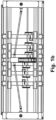
- the Figures 1a to 3c show the tool stamp 1 alone, partly with and partly without the cardboard tubes 100 that are open in terms of their cross section and are to be gripped.
- the tool stamp 1 consists of a frame-shaped base body 2, the largest surface extent of which is the main plane 2 ' - as in the Figures 2a -c marked - defined.
- These gripping rods 1a to 1f, 1A to 1F extend perpendicular to the main plane 2' in the axial direction 10, the Z direction.
- the transverse directions 11a, 11b, the X-direction and Y-direction, which span the main plane 2', are defined in such a way that the first transverse direction 11a or but especially in the main level 2 '.
- the longitudinal center plane 2" perpendicular to the main plane 2' runs in the middle of the extension of the base body 2 in the second transverse direction 11b, the Y direction.
- the base body 2 preferably the entire tool stamp 1 is designed as a mirror image of this long center plane 2".
- the main plane 2' of the base body 2 is generally horizontal, while the main extension direction 1' of the gripping elements or gripping rods and also the longitudinal center plane 2" are vertical.
- the frame-shaped base body 2 consists of two longitudinal struts 15a, which run parallel and at a distance from one another in the first transverse direction 11a and which are connected to one another at their respective analog free ends via a cross strut 15b to form a rectangle, lying parallel to the main plane 2 '.
- one of two traverse guides 13a, b is present on both sides, which also run in the X direction and are also firmly connected with their ends to one of the cross struts 15b.
- the spindle nuts 7a of all crossbars 5 rotate about the same axis of rotation, which runs parallel to the first transverse direction 11a.
- a non-rotatable threaded rod 7b which is fastened with its ends in the cross struts 15b and is in engagement with the spindle nuts 7a, extends along this axis of rotation, so that each cross member 5 is independent of the others by controlled drive of the individual motors 6a of the X-drives 6 - except for the fact that mutual overtaking in the X direction is not possible - it can be moved back and forth in the X direction within the movement range 1".
- Two gripping rods extend from each of the crossbars 5 - spaced apart from one another in the Y direction - downwards, i.e. in the axial direction 10, the Z direction.
- the two gripping rods 1f, 1F per crossbar 5 are movable relative to one another in the of the base body 2.
- each of the gripping rods 1f, 1F is attached at its upper end to a guide sleeve 9, which is movable in the Y direction relative to the cross strut 5.
- Each of the guide sleeves 9 has a through opening running in the a rod which runs through the through opening in the guide sleeves 9 and fits exactly into it, so that each guide sleeve 9 can be moved along one of the X-guides 3a, b.
- the X-guides 3a, b are round rods and the through openings of the guide sleeves 9 also have a matching round cross section.
- the X-guides 3a, b are fastened with their free ends in the cross struts 15d of the base body 2, but only fixed in the one of the cross struts 15b is housed, movable in counter-synchrony with one another.
- the twelve gripping rods in this case are thus divided into two displacement groups 1.1, 1.2:
- One half of the gripping rods 1a-1f is the displacement group 1.1 which is arranged in the identical Y position and is located in one end region of their respective Cross struts 5 are located, while the other half of the gripping rods 1A to 1F occupies a spaced-apart displacement group 1.2, but within the displacement group 1.2, a different Y position on the opposite side of the longitudinal center plane 2 "and these gripping rods 1A to 1F located in the other end region of their respective crossbars 5.
- FIG. 4c is shown enlarged in perspective, can be taken by starting from that in the Figures 2a -c shown state, the entire tool stamp 1 is lowered and thereby a specific gripping group of gripping bars is inserted into a cardboard sleeve 100 and then by moving the individual gripping bars in the X and Y directions along the base body 2 of the tool stamp 1 with respect to the cross-sectional center of the respective cardboard sleeve 100, the cardboard sleeve 100 is clamped to a free inner cross section 100 ', in particular by extending the gripping rods of the gripping group into the inner corners of the cross section 100' of the cardboard sleeve 100 in the main plane 2' until they have such a contact force on the inner surface 103 of the cardboard sleeve 100 rests so that the cardboard sleeve has a force fit on this gripping group is held by gripping rods and by moving, in particular raising and moving to the side, the entire tool stamp 1, the one or more cardboard tubes 100 held
- one or more cardboard tubes 100 can be gripped at the same time: For gripping a cardboard tube 100 with a rectangular cross section - as in Figure 3a shown - only one gripping group consisting of four gripping rods 1a, 1A, 1b, 1B arranged in a rectangle is required, so that by means of the existing twelve gripping rods 1a to 1f, 1A to 1F, which are arranged in two displacement groups 1.1, 1.2, simultaneously up to three cardboard tubes 100 with a rectangular cross-section can be handled, provided that their cross-sections are small enough to be able to arrange these three vertically extending cardboard tubes 100 next to each other, i.e. in a row extending in the X direction, within the movement range 1 "below the gripping bars.
- Such an open cardboard tube - as in Figure 4c shown - has, on the one hand, a sleeve body 104, consisting of the four side walls 100a-d which adjoin one another in the circumferential direction around the free cross section and are connected to one another in an articulated manner.
- a sleeve body 104 At the lower end 104a of the sleeve body 104 - preferably aligned with the respective side wall 100a-d of the sleeve body 104, i.e. running vertically - there is a lower pivot tab 105a-d, from which the base 106 is later formed by pivoting inwards and gluing against each other boxes to be produced from the cardboard tube.
- each side wall 100a-d is usually adjoined at the upper end by such a pivoting tab 105a-d, from which a closed top of the box is later created only after the box has been filled.
- such an open cardboard tube 100 therefore has a free inner cross section 100 'continuous from the upper open side 101 to the lower open side 102, into which the gripping rods can be inserted from above, preferably until the lower one free end of the gripping rods - which are preferably all at the same height in the Z direction - are at the level of the lower end of the cardboard body 104 or just above.
- the gripping rods have a rectangular, preferably square, cross-section, with which cardboard tubes 100 with a rectangular inner cross-section or with inner cross-sections whose inner corners each have an inner angle of at least 90 ° can be clamped and gripped in the main plane 2 '.
- the gripping rods could also have an external cross section in the form of a right-angled triangle.
- an equilateral triangle can also be chosen - as in Figure 3b shown at the top left - or a triangular shape in which the triangle angle at one corner of the triangle is less than 60 °, which means that even smaller internal angles could be approached in a cardboard tube 100, as can occur, for example, in a triangular cardboard tube.
- the length of the gripping rods is designed for the longest axial length of cardboard tubes 100 that can be handled.
- the base body 2 is at a relatively large distance above the upper end of the Cardboard tubes 100.
- this additional cross member 5' is only located in the free distance between the two gripping rods to be supported, this additional cross member 5' can also be retracted into the inner free cross section 100' of the cardboard tube 100 when gripping cardboard tubes 100.
- the gripping rod at the upper end can be pivoted relative to the guide sleeve 9 about a pivot axis 17, which lies parallel to the main plane 2 'at an angle to the X and Y directions that is adapted to the cross-sectional shape of the cardboard sleeve to be gripped, and preferably the gripping rod itself is pivotable about the Z direction.
- a contact element can - especially in this case - be placed at at least one point on the outer circumference of the gripping bar 18 can be arranged, which can be moved not only in the axial direction along the gripping rod, but also relative to it about a further pivot axis 17', preferably parallel to the pivot axis 17, in any case at least around a further pivot axis 17' lying transversely to the Z direction, preferably in the main plane 2 '. be pivotable.
- the contact element 18 has an outer contour which is suitable for resting on the inner contour of the cardboard tube to be gripped, preferably in one of its inner corners, preferably in the form of an angle profile, as in Figure 3b shown below left.
- round cardboard tubes can also be gripped, as in Figure 3b shown on the far right by sliding a contact element 18 onto a gripping rod with a polygonal, for example square, cross-section, which has an outer contour in the form of a circular segment, the radius of curvature of which is equal to or slightly smaller than the radius of curvature of the circular inner circumferential contour of the cardboard tube 100 to be gripped.
- a polygonal, for example square, cross-section which has an outer contour in the form of a circular segment, the radius of curvature of which is equal to or slightly smaller than the radius of curvature of the circular inner circumferential contour of the cardboard tube 100 to be gripped.
- Fig. 2a show the Fig. 2b the case that two cardboard tubes arranged next to one another - again rectangular in cross section - are gripped by the tool stamp 1 at the same time, but the dimensions of the cross section of this type of cardboard tube are so large that in the first transverse direction 11a, the X direction of the tool stamp 1 , only two such cardboard tubes 100 a, b can be arranged within the movement range 1" of the gripping elements, i.e. here the gripping rods.
- the four gripping rods that are not required can also be arranged in pairs - for example because there is not enough space available for the aforementioned arrangement - inside the free cross section 100 'of one of the two cardboard tubes 100a, b, as in Fig.
- a gripping group for gripping the cardboard sleeve 100a consists of the six gripping bars, for example 1a - 1c and 1A - 1C, although after immersion in the cardboard sleeve 100a, preferably only the four outer gripping bars 1a, 1A, 1c, 1C are in the gripping position, i.e outwards into the inner corners of the rectangular cardboard tube 100, while the two middle gripping rods 1b, B preferably remain in their initial position.
- the gripping group to be lowered into the free inner cross section 100 'of this cardboard sleeve 100 can also include all 12 gripping bars 1a - f, 1A - F, whereby after lowering into the cardboard sleeve 100 only preferably the outer four gripping bars 1a, A, 1f, F can be extended into the gripping position, i.e. into the inner corners of the rectangular free cross section 100' of the cardboard tube 100 in the main plane 2'.
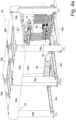
- FIG. 4a the entire handling device 30 is shown, including the supporting frame 34 consisting of the vertical posts 34a, which are connected at the upper end by upper horizontal traverses 34b running in both horizontal directions, and at the lower end by preferably also in both horizontal directions -Lower horizontal trusses 34c running in different directions.
- this frame 34 is in Fig. 4b , which however depicts a slightly different work situation, is omitted.
- the handling device 30 includes: On the one hand, the box opener 40, which removes the last one from a supply stack 51 of flat-folded boxes 99 - as shown in the Fig. 7a - c explained - and at a defined gripping position in the open state, i.e. as an open cardboard tube 100, for gripping by the tool stamp 1, as in the Fig. 2a - c shown.
- the box opener 40 which removes the last one from a supply stack 51 of flat-folded boxes 99 - as shown in the Fig. 7a - c explained - and at a defined gripping position in the open state, i.e. as an open cardboard tube 100, for gripping by the tool stamp 1, as in the Fig. 2a - c shown.
- the tool stamp 1 is lifted here by means of a lifting device 35 in the form of a scissor linkage 35, which engages at its lower end on the base body 2 of the tool stamp 1, and is fastened at its upper end to a carriage 32, which runs along guides 33 in the form of Rails can be moved in the and lowered, for example also placed on the ground.
- a lifting device 35 in the form of a scissor linkage 35, which engages at its lower end on the base body 2 of the tool stamp 1, and is fastened at its upper end to a carriage 32, which runs along guides 33 in the form of Rails can be moved in the and lowered, for example also placed on the ground.
- a controller 30 controls all movements of all movable parts of the handling device 30, including those of the tool stamp 1.
- FIG. 4a shows the tool stamp 1 in the waiting position so that the cardboard erector 40 provides a new set of open, graspable cardboard tubes 100 Fig. 5a in the side view the state while the gripping groups of gripping elements 1a - f, A - F are just being lowered into the three open cardboard tubes 100a - c provided next to each other by lowering the tool stamp 1.
- Fig. 4b shows one step further the movement of the tool stamp 1 by means of the movement device 31 in the X direction with the three cardboard tubes 100a - c hanging on it and gripped by the tool stamp 1.
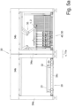
- Fig. 6a shows how the tool stamp 1 has already moved the three cardboard sleeves 100a, b, c over the beginning of the base closing device 20 and places them on their rail-shaped counterholder 21 with their already closed bases 106, and these are currently being glued.
- the gripping elements 1a - 1F are preferably moved further down in the Z direction until they press on the top of the swivel tabs 105a, b located above and thus open the adhesive spots preferably applied underneath.
- the front view of the Fig. 5b shows the same situation as Fig. 5a in the viewing direction X, in which the gripping elements of the tool stamp 1 move straight into the cardboard tubes 100a - c.
- Fig. 5b and Fig. 6b So show in the front view of the handling device 30, on the one hand, the gripping of the cardboard tubes 100 and, on the other hand, the placing of their bottoms 106.
- the lifting device 35 here in the form of the scissor linkage 35, is designed to be movable in a controlled manner along the carriage 32 in the Y direction, and thus the carriage 1 not only in the X and Z directions, but also in the Y direction.
- Direction can be designed to be movable to a limited extent.
- the inclined surface 43 can also be seen, which usually extends outside the frame 34 of the handling device 30, and on which the supply stack 51 of essentially upright, adjacent, flat-folded cardboard tubes 99 automatically slides into place
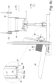
- Direction of the box opener 40 which enlarges in the Fig. 7a - c is shown in different functional positions: This shows Fig.
- both positions of the box opener 40 Since in this case three cardboard tubes 100a, b, c, next to each other are to be gripped simultaneously by the tool stamp 1, the cardboard opener 40 in this case comprises three opening units 44, which are arranged in the X direction along two guide rods arranged one above the other at a distance parallel to one another 45a, b of an X-guide 45 can be moved and adjusted so that they are in the in Fig. 7a
- the docking position shown at the top right is in the correct places on the first flat-folded cardboard tubes 99 of the in Fig. 7c
- the more easily recognizable supply stack 51 which consists of three adjacent partial supply stacks, can dock.
- the opening units 44 move into the offering position Fig. 7a shown further to the left and slightly lower by moving the X-guide 45 along a Y-guide 46.
- the suction units 47 which are not completely vertical in the docking position but are slightly at an angle to the vertical, are pivoted into the vertical position in accordance with the inclination of the flat-folded cardboard sleeves 99 resting with their lower edge on the inclined surface 43, so that the now open cardboard sleeves 100 a - c held by the opening unit 44 are now vertical in the offering position.
- the offering position is already part of the gripping station 50, because in this offering position the gripping rods are inserted from above into the inner free cross section 100' of the open cardboard tubes 100.
- the two vertical struts which connect the two guide rods 45a, b at the ends and can be moved with their lower end in the Y-guide 46, can be pivoted about a pivot axis running parallel to the X-axis.
- Each suction unit 47 consists of a plate, on the front of which there are two or more suction cups 41 one above the other in order to suck on the outer surface of one of the side walls 100.1 facing them.
- the adjacent side walls 100.1 and 100.2 are pressed into a perpendicular position to one another, and the cardboard sleeve now has its open, rectangular, free inner cross section 100 ', as required for inserting the holding rods into the gripping station 50.
Landscapes
- Engineering & Computer Science (AREA)
- Mechanical Engineering (AREA)
- Making Paper Articles (AREA)
- Manipulator (AREA)
Description
Die Erfindung betrifft die Handhabung von hülsenförmigen sogenannten RSC (regular slotted card)-Kartons, die aus einer im Querschnitt polygonen, meist viereckigen, anfangs bei beidseits offenen, Hülse bestehen und im flach gefalteten, dann 2-lagigen, Zustand angeliefert werden. Für die weitere Handhabung, insbesondere das einseitige Verschließen des Bodens durch Verkleben, müssen die Hülsen maschinell gehandhabt werden.The invention relates to the handling of sleeve-shaped so-called RSC (regular slotted card) boxes, which consist of a sleeve with a polygonal cross-section, usually square, initially open on both sides, and are delivered in a flat, then 2-layer, condition. For further handling, in particular closing the base on one side by gluing, the sleeves must be handled mechanically.
Für die Zwecke der vorliegenden Erfindung wird von RSC-Kartons gesprochen, unabhängig davon, ob es sich bei der Hülse tatsächlich um ein Kartonmaterial oder ein beliebiges anderes Material, sei es Kunststoff oder Textilmaterial, handelt.For the purposes of the present invention, RSC cartons are referred to, regardless of whether the sleeve is actually a carton material or any other material, be it plastic or textile material.
Bisher wurden solche Kartons in einem ersten Schritt aus der flach gefalteten, 2-lagigen, Gestalt der Hülse zu einem polygonen Querschnitt aufgezogen, indem meist von zwei gegenüber liegenden Seiten in Querrichtung Sauger angriffen und die Karton-Hülse zu dem gewünschten polygonen Querschnitt auseinander gezogen haben, wobei die beiden Stirnseiten des hülsenförmigen Kartons noch offen waren.Previously, such boxes were, in a first step, drawn from the flat-folded, 2-layer shape of the sleeve to a polygonal cross-section, usually by suction cups attacking from two opposite sides in the transverse direction and pulling the cardboard sleeve apart to the desired polygonal cross-section , with the two front sides of the sleeve-shaped box still open.
In einem zweiten Schritt wurde dann ein innen angreifendes Greifwerkzeug von einer der offenen Stirnseiten in das Innere der Hülse, also des hülsenförmigen Kartons, eingebracht, welches Greifelemente radial zur axialen Richtung, also der von der einen zur anderen offenen Seite der Hülse verlaufenden Richtung, ausfuhr, bis diese mit einem ausreichend starken Anlagedruck an den Innenflächen der Hülse anlagen, um die Hülse vom Untergrund abheben und für die weitere Bearbeitung an einen anderen Ort transportieren und dort z.B. ablegen zu können.In a second step, an internally engaging gripping tool was then introduced from one of the open end faces into the interior of the sleeve, i.e. the sleeve-shaped cardboard, which extended gripping elements radially to the axial direction, i.e. the direction running from one open side of the sleeve to the other until they contact the inner surfaces of the sleeve with a sufficiently strong contact pressure to be able to lift the sleeve from the ground and transport it to another location for further processing and, for example, place it there.
Dabei tritt das Problem auf, dass die Fertigungstoleranzen bei solchen RSC-Kartons relativ groß sind, also nach Herstellen der Hülse im Überlappungsbereich der Enden des ursprünglichen Zuschnittes der Abstand der beiden überlappenden Endkanten - je nach Größe des Kartons - um bis zu 10 und auch mehr Millimeter variieren kann. Vor allem können diese Kanten durch nicht parallel, sondern winklig zueinander verlaufen, obwohl ein hülsenförmiger Karton mit über die Länge konstantem Querschnitt gewünscht ist.The problem that arises is that the manufacturing tolerances for such RSC boxes are relatively large, so after producing the sleeve in the overlapping area of the ends of the original blank, the distance between the two overlapping end edges - depending on the size of the box - by up to 10 or more Millimeters can vary. Above all, these edges can run not parallel to one another, but at an angle to one another, although a sleeve-shaped cardboard with a constant cross-section over the length is desired.
Die Ausfahrstrecke der Greifelemente aus dem Grundkörper des Werkzeugstempels muss diese Fertigungstoleranzen überbrücken können, jedoch ist auf der anderen Seite die Ausfahrlänge der Greifelemente durch den inneren Querschnitt des zu handhabenden hülsenförmigen Kartons, also der Hülse, begrenzt.The extension distance of the gripping elements from the base body of the tool stamp must be able to bridge these manufacturing tolerances, but on the other hand the extension length of the gripping elements is limited by the inner cross section of the sleeve-shaped cardboard to be handled, i.e. the sleeve.
Damit ist ein solcher Werkzeugstempel im Wesentlichen formatabhängig, denn er kann nur Hülsen mit geringfügig voneinander abweichenden Innenquerschnitten und Innendurchmessern handhaben, aber sobald sich die Innenquerschnitte im Durchmesser um den Faktor 1,5 oder gar 2,0 und mehr unterscheiden, ist ein entsprechend angepasstes neues Greifwerkzeug notwendig.This means that such a tool stamp is essentially format-dependent, because it can only handle sleeves with slightly different internal cross-sections and internal diameters, but as soon as the internal cross-sections differ in diameter by a factor of 1.5 or even 2.0 or more, a correspondingly adapted new one is required Gripping tool necessary.
Dies bedingt bei einem Formatwechsel lange Stillstands- und damit Ausfallzeiten der Anlage und darüber hinaus die Notwendigkeit, mehrere unterschiedliche Werkzeuge zur Verfügung zu stellen.When changing formats, this requires long downtimes and therefore downtimes for the system and also the need to provide several different tools.
Des Weiteren ist aus der
Es ist daher die Aufgabe gemäß der Erfindung, eine Handhabungs-Vorrichtung zu schaffen, welches die beschriebenen Nachteile vermeidet.It is therefore the object according to the invention to create a handling device which avoids the disadvantages described.
Diese Aufgabe wird durch die Merkmale des Anspruchs 1 gelöst. Vorteilhafte Ausführungsformen ergeben sich aus den Unteransprüchen.This task is solved by the features of
Hinsichtlich eines Verfahrens - welches nicht Bestandteil der Erfindung ist - wird diese Aufgabe dadurch gelöst, dass im Gegensatz zum Stand der Technik nicht der gesamte Werkzeugstempel einschließlich Grundkörper und daran befestigter Greifelemente in das Innere der offenen Karton-Hülse zum Ergreifen eingefahren wird, sondern lediglich die Greifelemente, während der Grundkörper, an dem die Greifelemente befestigt sind, dabei außerhalb der Karton-Hülse positioniert verbleibt.With regard to a method - which is not part of the invention - this object is achieved in that, in contrast to the prior art, not the entire tool stamp including the base body and gripping elements attached to it is moved into the interior of the open cardboard sleeve for gripping, but only the Gripping elements, while the base body to which the gripping elements are attached remains positioned outside the cardboard sleeve.
Der Vorteil dieser Vorgehensweise besteht darin, dass damit der Grundkörper in seiner Größe nicht auf den inneren freien Querschnitt der Karton-Hülse beschränkt ist, sondern wesentlich größer sein kann. Folglich können die Greifelemente ihre Position am Grundkörper in einem weiten Rahmen verändern und dadurch Karton-Hülsen ganz unterschiedlicher Abmessungen, also von sehr kleinen bis zu sehr großen Innenquerschnitten, von ein und demselben Werkzeugstempel ergriffen werden.The advantage of this approach is that the size of the base body is not limited to the inner free cross section of the cardboard sleeve, but can be significantly larger. Consequently, the gripping elements can change their position on the base body within a wide range and thereby cardboard sleeves of very different dimensions, i.e. from very small to very large internal cross sections, can be gripped by one and the same tool stamp.
Wird - wie im Stand der Technik - der Grundkörper dagegen mit in den Innenraum der Karton-Hülse eingeführt, ist dessen Erstreckung in der Querschnittsebene der Karton-Hülse begrenzt und damit aber auch - wenn die Greifelemente in dieser Querschnittsebene liegend aus dem Grundkörper herausverfahren werden - deren Ausfahrlänge, und somit können nur Karton-Hülsen mit begrenzt unterschiedlichem Querschnitt damit ergriffen werden.If - as in the prior art - the base body is introduced into the interior of the cardboard sleeve, its extension is limited in the cross-sectional plane of the cardboard sleeve and therefore also - if the gripping elements are moved out of the base body lying in this cross-sectional plane - their extension length, and therefore only cardboard tubes with a limited different cross-section can be gripped with it.
In der Regel werden - abgestimmt auf eine bestimmte zu ergreifende Karton-Hülse mit einem bestimmten freien inneren Querschnitt - zunächst die Positionen der Greifelemente am Grundkörper auf eine bestimmte Ausgangslage, passend zum freien inneren Querschnitt der zu ergreifenden Karton-Hülse, eingestellt, und nach dem Einführen der Greifelemente in die Karton-Hülse die Greifelemente - oder wenigstens einige der in die Karton-Hülse eingeführten Greifelemente - in eine Endlage verfahren, in der die Greifelemente, insbesondere alle Greifelemente, an der Innenfläche der Karton-Hülse anliegen und kraftschlüssig halten, so dass sie von dem Werkzeugstempel hochgehoben und wegtransportiert werden kann.As a rule - matched to a specific cardboard tube to be taken with a specific free inner cross section - first set the positions of the gripping elements on the base body to a specific starting position, matching the free inner cross section of the cardboard sleeve to be gripped, and after inserting the gripping elements into the cardboard sleeve, the gripping elements - or at least some of them in the Gripping elements inserted into the cardboard sleeve - move into an end position in which the gripping elements, in particular all gripping elements, rest on the inner surface of the cardboard sleeve and hold it in a non-positive manner, so that it can be lifted up and transported away by the tool stamp.
Vorzugsweise handelt es sich um im Querschnitt rechteckige Karton-Hülsen, und es werden dann vorzugsweise vier Greifelemente axial in die Innen-Ecken der Karton-Hülse eingeführt.These are preferably cardboard sleeves with a rectangular cross section, and four gripping elements are then preferably inserted axially into the inner corners of the cardboard sleeve.
Zum Bewegen von der Ausgangslage in die Endlage können die Greifelemente gegenüber dem Grundkörper entweder - wie für das Einnehmen der Ausgangslage - quer zur axialen Richtung, also vorzugsweise in der Hauptebene des Grundkörpers, linear in wenigstens einer, vorzugsweise beiden Querrichtungen, den beiden Richtungen der Hauptebene des Grundkörpers, verfahren werden.To move from the starting position to the end position, the gripping elements can be positioned relative to the base body either - as for assuming the starting position - transversely to the axial direction, i.e. preferably in the main plane of the base body, linearly in at least one, preferably both transverse directions, the two directions of the main plane of the base body.
Im erstgenannten Fall wird zumindest die Hälfte der in der zu ergreifenden Karton-Hülse eingebrachten Greifelemente in zwei lotrecht aufeinander stehenden Querrichtungen bewegt werden, während die übrigen Greifelemente in wenigstens einer dieser Querrichtungen bewegt werden.In the former case, at least half of the gripping elements introduced into the cardboard sleeve to be gripped will be moved in two transverse directions that are perpendicular to one another, while the remaining gripping elements will be moved in at least one of these transverse directions.
Dadurch wird erreicht, dass danach in der Endlage vorzugsweise alle in der Karton-Hülse befindlichen Greifelemente an der Innenfläche der Karton-Hülse anliegen und bei entsprechender Anpresskraft die Karton-Hülse nicht nur sicher daran gehalten ist, sondern durch die vorgegebene Endlage auch eine Form einnimmt, die weitestgehend der vorgesehenen Soll-Form, also dem Soll-Innenquerschnitt, der ergriffenen Hülse entspricht.This ensures that, in the end position, all gripping elements located in the cardboard sleeve preferably rest against the inner surface of the cardboard sleeve and, with the appropriate contact pressure, the cardboard sleeve is not only securely held thereon, but also takes on a shape due to the predetermined end position , which largely corresponds to the intended target shape, i.e. the target internal cross section, of the gripped sleeve.
Dazu werden die Greifelemente eben quer zur axialen Richtung so gesteuert, dass ihre Endlage relativ zueinander einer Anlage an dem Soll-Innenquerschnitt der Hülse entspricht oder anders ausgedrückt alle Greifelemente, die später in eine Karton-Hülse eingeführt werden sollen, vorher, in der Ausgangslage, innerhalb einer vorgegebenen Soll-Fläche liegen, die insbesondere gleich oder etwas kleiner als der Soll-Innenquerschnitt der zu handhabenden Karton-Hülse ist.For this purpose, the gripping elements are controlled transversely to the axial direction in such a way that their end position relative to one another corresponds to a contact with the target internal cross section of the sleeve or, in other words, all gripping elements that are to be inserted later into a cardboard sleeve beforehand, in the starting position, lie within a predetermined target area, which is in particular equal to or slightly smaller than the target internal cross section of the cardboard tube to be handled.
Wie weit die Greifelemente von der Ausgangslage in die Endlage bewegt werden, kann kraftgesteuert oder weggesteuert werden:
Bei einer Kraftsteuerung wird diese Bewegung durchgeführt, bis bei jedem einzelnen Greifelement eine vorgegebene Anpresskraft erreicht ist, was man beispielsweise messen kann anhand der Stromaufnahme des das Greifelement bewegenden Elektromotors.How far the gripping elements are moved from the starting position to the end position can be controlled by force or distance:
With force control, this movement is carried out until a predetermined contact force is reached for each individual gripping element, which can be measured, for example, based on the current consumption of the electric motor moving the gripping element.
Bei einer Wegsteuerung wird Richtung und Strecke vorgegeben, die das Greifelement von der Ausgangslage bis zur Endlage zurücklegt. Weichen die Innenquerschnitte der Karton-Hülsen jedoch stark von dem Soll-Innenquerschnitt ab aufgrund geringer Maßhaltigkeit beim Herstellen der Karton-Hülsen, so besteht die Gefahr, dass die Karton-Hülsen dabei zerreißen.With path control, the direction and distance that the gripping element covers from the starting position to the end position is specified. However, if the internal cross-sections of the cardboard sleeves deviate significantly from the target internal cross-section due to poor dimensional accuracy when producing the cardboard sleeves, there is a risk that the cardboard sleeves will tear in the process.
Vorzugsweise werden die Greifelemente soweit axial in die Hülse eingefahren, dass sie mit ihrem vorderen freien Ende das untere freie Ende des Hülsen-Korpus, also der Karton-Hülse, ohne die an den Stirnseiten noch vorhandenen Schwenklaschen, die später den Boden bilden, erreichen oder fast erreichen.Preferably, the gripping elements are retracted axially into the sleeve to such an extent that their front free end reaches the lower free end of the sleeve body, i.e. the cardboard sleeve, without the swivel tabs still present on the end faces, which later form the bottom almost reach.
Zum einen wird dadurch erreicht, dass die Greifelemente vorzugsweise über die gesamte axiale Erstreckung des Hülsen-Korpus auf diesen eine dem Innenquerschnitt formende Wirkung ausüben, zum anderen kann dadurch das Schließen und Verkleben des Bodens erleichtert werden:
Denn der Boden einer viereckigen, zunächst noch beidseits offenen, Karton-Hülse wird ja dadurch geschlossen, dass die an allen vier Seitenwänden am stirnseitigen Ende je eine vorhandene Schwenklasche herumgeklappt werden in eine Querebene des Hülsen-Korpus und dort gegeneinander verklebt werden.On the one hand, this ensures that the gripping elements exert a shaping effect on the inner cross section of the sleeve body over the entire axial extent of the sleeve body, and on the other hand, this can make closing and gluing the base easier:
The bottom of a square cardboard sleeve, which is initially open on both sides, is closed by folding the swivel tabs on all four side walls at the front end into a transverse plane of the sleeve body and gluing them together there.
Dieses Verkleben wird verbessert, indem sich die Klebestellen unter Anderem oder ausschließlich unter der frei endenden Stirnfläche der Greifelemente befinden, und nach dem Umlegen die überlappenden und in axialer Richtung aneinander anliegenden Schwenklaschen mit dem Kleber dazwischen in axialer Richtung gegeneinander gepresst werden, indem von der Innenseite her die Greifelemente mit ihren Stirnseiten gegen die Innenseite des Bodens drücken, und sich die Außenseite des Bodens auf dem Untergrund oder einem Gegenhalter abstützt.This bonding is improved in that the bonding points are located, among other things or exclusively, under the free-ending end face of the gripping elements, and after folding the overlapping pivot tabs that lie against one another in the axial direction with the adhesive in between are pressed against one another in the axial direction by coming from the inside The gripping elements press their front sides against the inside of the floor, and the outside of the floor is supported on the surface or a counter support.
Falls der Querschnitt der Karton-Hülse mehr als vier Ecken hat, beispielsweise sechs oder acht Ecken, wird in der Regel auch eine entsprechende Anzahl von Greifelementen in die Karton-Hülse eingeführt werden, denn in aller Regel sollen sich die Greifelemente an den Innenecken der Karton-Hülse anlegen.If the cross section of the cardboard sleeve has more than four corners, for example six or eight corners, a corresponding number of gripping elements will usually be inserted into the cardboard sleeve, because as a rule the gripping elements should be on the inside corners of the cardboard -Put on the sleeve.
Wenn jedoch an einem Grundkörper mehr als die für das Ergreifen einer Hülse erforderliche Anzahl an Greifelementen, also insbesondere mehr als vier, vorhanden sind, können bei beispielsweise zwölf Greifelementen bis zu drei rechteckige Karton-Hülsen gleichzeitig von einem Werkzeugstempel ergriffen werden, sofern der Grundkörper ausreichend groß ist, dass er sich über alle drei nebeneinander befindlichen Karton-Hülsen, also über deren Querschnittsflächen, hinweg erstrecken kann.However, if there are more gripping elements on a base body than the number required to grip a sleeve, i.e. in particular more than four, then with twelve gripping elements, for example, up to three rectangular cardboard sleeves can be gripped at the same time by a tool stamp, provided that the base body is sufficient is large in that it can extend over all three cardboard sleeves located next to each other, i.e. over their cross-sectional areas.
Dann werden - bei der Einstellung für einen solchen mehrzeiligen Betrieb - die Greifelemente auf solche Ausgangslagen eingestellt, dass sich jeweils die für das Ergreifen einer Karton-Hülse vorgesehene Gruppe von Greifelementen in die vorgesehene der mehreren nebeneinander angeordneten Karton-Hülsen axial eingefahren werden kann, indem der gesamte Grundkörper, der die mehreren Gruppen von Greifelementen trägt, sich axial in Richtung auf die offenen Stirnseiten der nebeneinander angeordneten Karton-Hülsen zubewegt.Then - when setting for such a multi-line operation - the gripping elements are set to such starting positions that the group of gripping elements intended for gripping a cardboard tube is axially retracted into the intended one of the several cardboard tubes arranged next to one another can be done by the entire base body, which carries the several groups of gripping elements, moving axially towards the open end faces of the cardboard tubes arranged next to one another.
Wenn dagegen die Anzahl der gleichzeitig zu ergreifenden Karton-Hülsen gleich bleibt und sich nur die Abmessung und/oder Form von deren Innenquerschnitt ändert, bleibt die Gruppenzuordnung zu den einzelnen Karton-Hülsen bzw. deren Innenquerschnitten gleich, es müssen lediglich die Ausgangslagen der einzelnen Greifelemente auf das neue Maß des neuen Innenquerschnittes abgestimmt werden.If, on the other hand, the number of cardboard tubes to be gripped at the same time remains the same and only the dimensions and/or shape of their internal cross-section changes, the group assignment to the individual cardboard tubes or their internal cross-sections remains the same; only the initial positions of the individual gripping elements need to be determined be adapted to the new dimension of the new internal cross section.
Auf diese Art und Weise können Karton-Hülsen mit sehr kleinem inneren Querschnitt ergriffen werden, wobei die Begrenzung darin liegt, wie eng die Greifelemente gegenseitig aneinander heranfahrbar sind zum Einnehmen einer Ausgangslage, oder es kann eine einzelne Karton-Hülse mit einem demgegenüber vielfach größeren freien inneren Querschnitt ergriffen und gehalten werden, begrenzt lediglich durch den Bewegungsbereich der Greifelemente innerhalb der Grundfläche des Grundkörpers, so dass eine solche Karton-Hülse einen Querschnitt bis annähernd der Erstreckung des Grundkörpers in seiner Hauptebene besitzen kann.In this way, cardboard tubes with a very small internal cross section can be gripped, the limitation being how closely the gripping elements can be moved towards one another in order to assume a starting position, or a single cardboard tube can be gripped with a much larger free one inner cross section are gripped and held, limited only by the range of movement of the gripping elements within the base area of the base body, so that such a cardboard sleeve can have a cross section up to approximately the extent of the base body in its main plane.
Damit die Greifelemente axial in den freien inneren Querschnitt der Karton-Hülse eingefahren werden können zum Ergreifen der Karton-Hülse, müssen die Karton-Hülsen, die als zweilagig flach gefaltete Hülsen ohne nennenswerten freien inneren Querschnitt angeliefert werden, zunächst zu offenen Karton-Hülsen, also mit einem freien inneren Querschnitt entsprechend annähernd dem Soll-Querschnitt, geöffnet werden.So that the gripping elements can be moved axially into the free inner cross section of the cardboard tube in order to grip the cardboard tube, the cardboard tubes, which are delivered as two-layer flat folded tubes without a significant free inner cross section, must first be converted into open cardboard tubes. i.e. with a free inner cross section corresponding approximately to the target cross section.
Erfindungsgemäß wird dies dadurch erreicht, indem eine erste Seitenwand mittels eines Saugers oder einer Saugereinheit, die mehrere Sauger enthält, ergriffen und damit die flach gefaltete Karton-Hülse von einem Vorrats-Stapel abgenommen wird. Bereits bei dieser Abnahmebewegung oder anschießend in einer separaten Arbeitsposition im Stillstand kann die an diese erste Seitenwand angrenzende und in der flach gefalteten Lage in derselben Ebene liegende zweite Seitenwand in eine gewinkelte Lage, vorzugsweise eine rechtwinklige Lage, zu der ersten Seitenwand verschwenkt, also geklappt, werden, wodurch sich die Karton-Hülse im offenen Zustand befindet.According to the invention, this is achieved by gripping a first side wall using a suction cup or a suction unit that contains several suction cups and thus removing the flat-folded cardboard sleeve from a storage stack. Already during this removal movement or subsequently in a separate working position while at a standstill, the second side wall, which is adjacent to this first side wall and lies in the same plane in the flat folded position, can be pivoted into an angled position, preferably a right-angled position, relative to the first side wall, i.e. folded. so that the cardboard tube is in the open state.
Nach dem erfindungsgemäßen Ergreifen wird die Karton-Hülse in der Regel zu einer Schließstation bewegt, in der der Boden wie zuvor beschrieben geschlossen wird.After gripping according to the invention, the cardboard sleeve is usually moved to a closing station in which the base is closed as previously described.
Erfindungsgemäß erfolgt dabei das Verschwenken der Schwenklaschen in die Querebene so, dass bereits während der Transportbewegung die in Transportrichtung verlaufenden, einander gegenüberliegenden Schwenklaschen einer Karton-Hülse mit rechteckigem Querschnitt so über ein stillstehend angeordnetes oder auch bewegtes Leitelement bewegt werden, dass dadurch dieses erste Paar von Schwenklaschen in die Querebene umgelegt wird.According to the invention, the pivoting tabs are pivoted into the transverse plane in such a way that, during the transport movement, the opposing pivoting tabs of a cardboard tube with a rectangular cross-section running in the transport direction are moved over a stationary or moving guide element in such a way that this first pair of Swivel brackets are folded into the transverse plane.
Anschließend werden - gegebenenfalls ebenfalls bereits während der Bewegung - die beiden Schwenklaschen des anderen Paares von Schwenklaschen ebenfalls in die Querebene umgelegt und vorher oder dabei Kleber zwischen die dann zwei aufeinanderliegenden Lagen von Schwenklaschen eingebracht, denn jedes Paar voneinander gegenüberliegenden Schwenklaschen bedeckt - umgelegt in die Querebene - vorzugsweise den gesamten inneren freien Querschnitt der vorher beidseits offenen Karton-Hülse.Then - if necessary also during the movement - the two swivel tabs of the other pair of swivel tabs are also folded into the transverse plane and before or at the same time glue is introduced between the then two layers of swivel tabs lying on top of each other, because each pair of swivel tabs that are opposite one another covers - folded over into the transverse plane - preferably the entire inner free cross section of the cardboard tube that was previously open on both sides.
Dass die Klebestellen in den Ecken oder unter den Querschnittsflächen der Greifelemente dann mittels dieser festgedrückt werden, wurde bereits dargelegt.It has already been explained that the adhesive points in the corners or under the cross-sectional areas of the gripping elements are then pressed firmly by means of them.
Der Vorteil dieser Vorgehensweise besteht - vor Allem bei einem mehrzeiligen Betrieb - darin, dass die Transportrichtung diejenige Richtung ist, in der sich die mehreren gleichzeitig zu ergreifenden Karton-Hülsen für das Ergreifen hintereinander angeordnet sind, also in aller Regel die erste Querrichtung des Grundkörpers des Werkzeugstempels.The advantage of this approach - especially in multi-line operation - is that the transport direction is the direction in which the several cardboard tubes to be gripped at the same time are arranged one behind the other for gripping, i.e. generally the first transverse direction of the base body of the tool stamp.
Dadurch können die mehreren von demselben Werkzeugstempel ergriffenen und gehaltenen Karton-Hülsen in einem Arbeitsgang sehr schnell hintereinander geschlossen werden, wie später im Detail erläutert.As a result, the several cardboard sleeves gripped and held by the same tool stamp can be closed very quickly one after the other in one operation, as explained in detail later.
Dabei kann es unter Umständen auch vorteilhaft sein, wenn mit nicht nur einem, sondern zum Beispiel zwei oder gar mehreren Werkzeugstempeln gearbeitet wird, sodass während des Schließens der Böden der von dem einen ersten Werkzeugstempel momentan gehaltenen Karton-Hülsen ein anderer Werkzeugstempel bereits einen neuen Satz von Karton-Hülsen ergreift.It may also be advantageous under certain circumstances to work with not just one, but for example two or even more tool stamps, so that while the bottoms of the cardboard sleeves currently held by the first tool stamp are closed, another tool stamp is already producing a new set of cardboard tubes.
Diese Aufgabe wird gelöst durch eine Handhabungs-Vorrichtung nach Anspruch 1.This task is solved by a handling device according to
In der Regel ist im Betrieb der Vorrichtung die Hauptebene des Grundkörpers horizontal ausgerichtet und die Greifelemente erstrecken sich in der Vertikalen, und zwar vom Grundkörper aus vorzugsweise nach unten.As a rule, during operation of the device, the main plane of the base body is aligned horizontally and the gripping elements extend vertically, preferably downwards from the base body.
Die Hauptebene des Grundkörpers, nämlich diejenige Ebene, in der der Grundkörper seine größte flächige Erstreckung besitzt, liegt im Betrieb in der Regel horizontal.The main plane of the base body, namely the plane in which the base body has its largest surface extent, is generally horizontal during operation.
Die Haupterstreckungsrichtung der Greifelemente erstreckt sich lotrecht zu dieser Hauptebene, zumindest jedoch primär lotrecht zur Hauptebene, so dass bei einer schräg zur Hauptebene verlaufenden Haupterstreckungsrichtung deren größte Richtungskomponente die vertikale zur Hauptebene ist.The main direction of extension of the gripping elements extends perpendicular to this main plane, but at least primarily perpendicular to the main plane, so that if the main extension direction runs obliquely to the main plane, its largest directional component is the vertical one to the main plane.
In einer bevorzugten Ausführungsform sind die Greifelemente gerade Stangen oder gerade Rohre, vorzugsweise mit geschlossenem vorderen, insbesondere unteren, freien Ende.In a preferred embodiment, the gripping elements are straight rods or straight tubes, preferably with a closed front, in particular lower, free end.
Ebenfalls vorzugsweise besitzen die Greifelemente wenigstens über einen Teil ihrer Erstreckung einen polygonen, insbesondere rechteckigen, insbesondere quadratischen Außenumfang quer zu ihrer Haupterstreckungsrichtung.Also preferably, the gripping elements have a polygonal, in particular rectangular, in particular square outer circumference transverse to their main direction of extension, at least over part of their extent.
Dadurch ist es möglich, dass zum Ergreifen der Karton-Hülsen der Werkzeugstempel die Greifelemente in Richtung deren Haupterstreckung, insbesondere in der Lotrechten zur Hauptebene des Grundkörpers, der axialen Richtung, in die eine offene Seite der zu ergreifenden einen oder mehreren Karton-Hülsen einführt, und diese die Karton-Hülse ergreift, während der Grundkörper außerhalb der Karton-Hülsen verbleibt.This makes it possible for the tool stamp to grip the cardboard sleeves by moving the gripping elements in the direction of their main extension, in particular in the perpendicular to the main plane of the base body, the axial direction into which an open side of the one or more cardboard sleeves to be gripped leads. and this grips the cardboard sleeve while the base body remains outside the cardboard sleeve.
Vorzugsweise besitzt der Grundkörper in wenigstens einer, vorzugsweise in beiden Richtungen seiner Hauptebene, also den Querrichtungen zur axialen Richtung, eine größere Erstreckung, als der Bewegungsbereich, in dem sich die Werkzeugstempel in der Hauptebene des Grundkörpers bewegen können.The base body preferably has a greater extent in at least one, preferably in both directions of its main plane, i.e. the transverse directions to the axial direction, than the range of movement in which the tool stamps can move in the main plane of the base body.
Vorzugsweise ist diese Erstreckung des Grundkörpers in einer oder beiden Richtungen seiner Hauptebene auch größer als der innere freie Querschnitt der größten durch den Werkzeugstempel handhabbaren Karton-Hülse.Preferably, this extension of the base body in one or both directions of its main plane is also larger than the inner free cross section of the largest cardboard sleeve that can be handled by the tool stamp.
Der Grundkörper weist Führungen auf, die in zwei sich kreuzenden Richtungen seiner Hauptebene, den beiden lotrecht aufeinander stehenden Querrichtungen, verlaufen, entlang der die Greifelemente - vorzugsweise einzeln und unabhängig voneinander, oder zumindest paarweise unabhängig voneinander - verfahrbar sind.The base body has guides which run in two intersecting directions of its main plane, the two transverse directions which are perpendicular to one another, along which the gripping elements can be moved - preferably individually and independently of one another, or at least in pairs independently of one another.
Diejenige erste Querrichtung, in der der Grundkörper in seiner Hauptebene die größte Erstreckung aufweist, wird kurz als X-Richtung bezeichnet, die darauf lotrecht stehende andere Querrichtung der Hauptebene als Y-Richtung.The first transverse direction in which the base body has the greatest extent in its main plane is briefly referred to as the
Dabei ist eine erste Gruppe der Greifelemente entlang einer ersten X-Führung, die in X-Richtung verläuft, verfahrbar und eine zweite Gruppe der Greifelemente entlang einer zweiten, dazu parallelen, X-Führung gesteuert verfahrbar.A first group of gripping elements can be moved along a first X-guide, which runs in the X direction, and a second group of gripping elements can be moved in a controlled manner along a second, parallel, X-guide.
Die X-Führungen sind - mit jeweils ihren beiden Enden - jeweils in einer in Y-Richtung verlaufenden Y-Führung verfahrbar, und dadurch in ihrem Abstand zueinander einstellbar.The
Es umfassen die beiden Gruppen jeweils eine gleiche Anzahl von Greifelementen, und je ein Greifelement der einen Reihe ist mit je einem Greifelement der anderen Reihe, insbesondere dem genau gegenüberliegenden Greifelement, über eine Quertraverse verbunden, so dass jedes Paar von Greifelementen nur gemeinsam in X-Richtung verfahren werden kann und sich ihre Relativlage in X-Position zueinander nicht verändern lässt, insbesondere die beiden Greifelemente jedes Paares von Greifelementen sich jeweils auf der gleichen X-Position befindet. In letzterem Fall verläuft die Quertraverse genau in Y-Richtung.The two groups each comprise an equal number of gripping elements, and one gripping element from one row is connected to one gripping element from the other row, in particular the gripping element located exactly opposite, via a crossbar, so that each pair of gripping elements can only be connected together in X Direction can be moved and their relative position in the X position to one another cannot be changed, in particular the two gripping elements of each pair of gripping elements are each in the same X position. In the latter case, the crossbar runs exactly in the Y direction.
In Y-Richtung können die beiden Greifelemente eines Paares ihren Abstand zueinander ändern aufgrund der Abstandsveränderung der beiden X-Führungen zueinander, an denen die beiden Greifelemente des Paares geführt sind.In the Y direction, the two gripping elements of a pair can change their distance from one another due to the change in distance between the two X-guides on which the two gripping elements of the pair are guided.
In X-Richtung verfügt zumindest jede Quertraverse, vorzugsweise jedes einzelne Greifelement, über einen X-Antrieb, mit dem die Quertraverse oder das einzelne Greifelement in X-Richtung gesteuert verfahrbar ist.In the X direction, at least each cross member, preferably each individual gripping element, has an
Der Vorteil ist, dass für die Bewegung in X-Rich tung pro Paar nur ein Antrieb notwendig ist, der Nachteil besteht darin, dass die beiden Greifelemente eines Paares ihren Abstand in X-Richtung zueinander nicht ändern können. Somit ist eine solche Lösung mit gekoppellen Paaren von Greifelementen vorzugsweise für Karton Hülsen mit rechteckigem Innenquerschnitt geeignet.The advantage is that only one drive per pair is necessary for movement in the X direction. The disadvantage is that the two gripping elements of a pair cannot change their distance from one another in the X direction. Thus, such a solution with coupled pairs of gripping elements is preferably suitable for cardboard sleeves with a rectangular internal cross section.
Wenn andere Querschnittsformen ebenfalls bewältigbar sein sollen, sind vorzugsweise die einzelnen Greifelemente in beide Querrichtungen jeweils unabhängig voneinander verfahrbar.If other cross-sectional shapes should also be manageable, the individual gripping elements can preferably be moved independently of one another in both transverse directions.
Eine besonders gut geeignete Außenumfangsform der Greifelemente wäre dann eine dreieckige Umfangsform, insbesondere in Form eines gleichseitigen Dreiecks oder eines rechteckigen Dreiecks.A particularly suitable outer peripheral shape of the gripping elements would then be a triangular peripheral shape, in particular in the form of an equilateral triangle or a rectangular triangle.
Vorzugsweise ist zwischen den über die Traverse miteinander verbundenen beiden Greifelementen eines Paares in Axialrichtung beabstandet eine weitere Quertraverse vorhanden, die in axialer Richtung, in Z-Richtung, zur ersten Quertraverse gesteuert verstellbar ist.Preferably, between the two gripping elements of a pair that are connected to one another via the crossbar, there is a further crossbar spaced apart in the axial direction, which can be adjusted in a controlled manner in the axial direction, in the Z direction, to the first crossbar.
Da die Greifelemente vorzugsweise in ihrer Haupterstreckungsrichtung so lang sind, wie der längste handhabbare Hülsen-Korpus sein kann, besitzen diese Greifelemente eine erhebliche axiale Erstreckung, so dass an ihrem endseitigen Befestigungspunkt gegenüber dem Grundkörper erhebliche Drehmomente auftreten.Since the gripping elements are preferably as long in their main direction of extension as the longest handleable sleeve body can be, these gripping elements have a considerable axial extension, so that considerable torques occur at their end attachment point relative to the base body.
Zumindest bei dem Ergreifen von Karton-Hülsen, die eine demgegenüber wesentlich kürzere axiale Länge besitzen, können die beiden Greifelemente eines Paares gegeneinander versteift werden, indem die bewegliche Quertraverse beim Ergreifen oder schon vor dem Ergreifen in eine Axialposition nahe an der Karton-Hülse heran gefahren wird.At least when gripping cardboard sleeves, which have a significantly shorter axial length, the two gripping elements of a pair can be stiffened against each other by moving the movable crossbar into an axial position close to the cardboard sleeve when gripping or before gripping becomes.
Die erstgenannte Quertraverse, und/oder auch die zweitgenannte Quertraverse, kann in ihrer Längserstreckung, in der Regel der Y-Richtung, im Bereich zwischen den beiden dadurch verbundenen Greifelementen eines Paares teleskopierbar ausgebildet sein, und wenn diese Quertraversen nicht über den Zwischenraum zwischen den beiden Greifelementen hinausgehen, kann die wenigstens eine oder die beiden Quertraversen auch ins Innere der Karton-Hülse beim Ergreifen positioniert sein.The first-mentioned crossbar and/or the second-mentioned crossbar can have a longitudinal extension, usually in the Y direction, in the area between The two gripping elements of a pair connected thereby can be designed to be telescopic, and if these crossbars do not extend beyond the space between the two gripping elements, the at least one or the two crossbars can also be positioned inside the cardboard sleeve when gripping.
Oft steht jedoch die erste Quertraverse beidseits über den Abstand der beiden dadurch miteinander gekoppelten Greifelemente hinaus und die Quertraverse ist an ihren Enden in zusätzlichen Traversen-Führungen in X-Richtung geführt, zusätzlich zu der Führung der einzelnen Greifelemente an ihren jeweiligen X-Führungen.However, the first crossbar often protrudes on both sides beyond the distance between the two gripping elements coupled to one another and the crossbar is guided at its ends in additional crossbar guides in the X direction, in addition to the guidance of the individual gripping elements on their respective X-guides.
Dieser X-Antrieb besteht vorzugsweise aus einer Gewindestange und einer darauf verschraubbaren Spindelmutter, wobei vorzugsweise der Motor 6a des Antriebes die Spindelmutter antreibt und die Gewindestange in X-Richtung verläuft, und insbesondere auch eine der beiden X-Führungen sein kann.This X-drive preferably consists of a threaded rod and a spindle nut that can be screwed onto it, with the
Die Abstandsverstellung der beiden X-Führungen in Y-Richtung erfolgt mittels eines weiteren, zentralen, Motors, wobei vorzugsweise die Verfahrung so erfolgt, dass immer beide X-Führungen gegenläufig synchron zum Grundkörper bewegt werden, also zur Längsmitte des Grundkörpers beide X-Führungen immer den gleichen Abstand einnehmen, was die Steuerung vereinfacht. Falls die Greifelemente stangenförmig oder rohrförmig gestaltet sind, liegen sie mit ihrem Außenumfang beim Ergreifen vorzugsweise direkt an der Innenfläche der Karton-Hülse an mit der notwendigen Anlagekraft, um diese halten und hochheben zu können.The distance adjustment of the two occupy the same distance, which simplifies control. If the gripping elements are rod-shaped or tubular, their outer circumference preferably rests directly on the inner surface of the cardboard sleeve when gripped, with the necessary contact force to be able to hold and lift it.
In einer bevorzugten Ausführungsform kann an den Greifelementen jedoch auch jeweils wenigstens ein Kontaktelement auf der Außenseite so angebracht sein, dass beim Ergreifen einer Karton-Hülse nur diese Kontaktelemente an der Innenfläche der Hülse anliegen. Das Kontaktelement kann insbesondere schwenkbar, vorzugsweise frei schwenkbar oder einstellbar schwenkbar, - je nach Anwendungsfall - um eine beliebige Raumrichtung an dem Greifelement befestigt sein.In a preferred embodiment, however, at least one contact element can also be attached to the outside of the gripping elements in such a way that when gripping a cardboard sleeve, only these contact elements rest on the inner surface of the sleeve. The contact element can in particular be pivotally attached to the gripping element, preferably freely pivotable or adjustable, - depending on the application - about any spatial direction.
Vorzugsweise kann auch die Position des wenigstens einen Kontaktelementes entlang der Verlaufsrichtung des Greifelementes einstellbar sein, je nach Form und Größe der zu ergreifenden Karton-Hülse.Preferably, the position of the at least one contact element can also be adjustable along the direction of the gripping element, depending on the shape and size of the cardboard tube to be gripped.
Diese Kontaktelemente können auch abnehmbar, insbesondere vom freien Ende des zum Beispiel stangenförmigen Kontaktelementes her als Hülse aufschiebbar oder abziehbar sein.These contact elements can also be removable, in particular can be pushed on or removed as a sleeve from the free end of the, for example, rod-shaped contact element.
Der Vorteil solcher Kontaktelemente besteht darin, dass diese sehr gut an Material, Oberflächenbeschaffenheit, Querschnittsform oder andere Parameter der zu ergreifenden Karton-Hülse angepasst sein können.The advantage of such contact elements is that they can be very well adapted to the material, surface quality, cross-sectional shape or other parameters of the cardboard tube to be gripped.
Die Motoren, die die Greifelemente oder die Quertraversen in X- und Y-Richtung verfahren, sind entweder kraftgesteuert oder hinsichtlich ihres Fahrweges von der Ausgangslage aus gesteuert oder hinsichtlich des Erreichens der Endposition gesteuert.The motors that move the gripping elements or the crossbars in the X and Y directions are either force-controlled or controlled in terms of their travel path from the starting position or controlled in terms of reaching the end position.
Die Steuerung, die den Werkzeugstempel steuert, ist in der Lage, die Greifelemente - abhängig von der vorgegebenen Position und Form sowie Größe der zu ergreifenden Karton-Hülse so zu positionieren, dass sie in Gruppen zueinander angeordnet sind, insbesondere in Vierergruppen, so dass jede Gruppe in der Lage ist, axial in eine der zu ergreifenden Karton-Hülsen einzufahren.The control that controls the tool stamp is able to position the gripping elements - depending on the specified position and shape and size of the cardboard tube to be gripped - so that they are arranged in groups relative to one another, in particular in groups of four, so that each Group is able to move axially into one of the cardboard tubes to be gripped.
Für zu ergreifende Karton-Hülsen mit einem rechteckigen oder gar quadratischen Querschnitt werden dies in der Regel Vierergruppen sein.For cardboard tubes to be gripped with a rectangular or even square cross-section, these will usually be groups of four.
Abhängig von der Größe des Innenquerschnitts der Karton-Hülsen zur Erstreckung des Grundkörpers in dessen Hauptebene und insbesondere der Größe des Bewegungsbereiches der Greifelemente entlang dieser Hauptebene können mittels der Greifelemente des Grundkörpers nicht nur eine Karton-Hülse, sondern mehrere gleichzeitig ergriffen werden. Diese sind dann in der Regel entlang der Haupterstreckungsrichtung, insbesondere entlang der Längsmitte des Grundkörpers, angeordnet, wenn die Greifelemente in die Karton-Hülsen eingefahren werden.Depending on the size of the inner cross section of the cardboard sleeves to extend the base body in its main plane and in particular the size of the range of movement of the gripping elements along this main plane, not only one cardboard sleeve but several can be gripped simultaneously by means of the gripping elements of the base body. These are then generally arranged along the main extension direction, in particular along the longitudinal center of the base body, when the gripping elements are inserted into the cardboard sleeves.
Wenn beispielsweise der Grundkörper sechs Paare von Greifelementen umfasst, können damit drei im Querschnitt rechteckige Karton-Hülsen gleichzeitig ergriffen werden, indem die Steuerung je zwei Paare zu einer Gruppe zusammenfasst. Werden aufgrund der Größe des Innenquerschnitts nur zwei im Querschnitt rechteckige Karton-Hülsen nebeneinander gleichzeitig ergriffen, kann jede Gruppe ebenfalls nur zwei Paare von Greifelementen umfassen, wenn es möglich ist, dass die beiden anderen Paare beim Ergreifen außerhalb der beiden Karton-Hülsen, also in einer deaktivierten Position, positioniert werden.For example, if the base body comprises six pairs of gripping elements, three cardboard tubes with a rectangular cross-section can be gripped simultaneously by the control combining two pairs into a group. If, due to the size of the internal cross-section, only two cardboard tubes with a rectangular cross-section are gripped side by side at the same time, each group can also only include two pairs of gripping elements if it is possible for the other two pairs to grip outside the two cardboard tubes, i.e. in a deactivated position.
Die Gruppen für die beiden Karton-Hülsen können dann aber auch jeweils drei Paare von Greifelementen umfassen, wobei die Greifelemente der beiden äußeren Paare zum Ergreifen jeweils in die Innenecken der Karton-Hülse gefahren werden, das mittlere Paar dagegen höchstens lose an den Innenseiten der rechteckigen Karton-Hülse anliegt, jedoch in der Regel keinen Druck nach außen gegenüber diesen ausüben darf, da dadurch die Karton-Hülse unzulässig nach außen verformt würde.The groups for the two cardboard sleeves can then each include three pairs of gripping elements, with the gripping elements of the two outer pairs being moved into the inner corners of the cardboard sleeve for gripping, while the middle pair is at most loosely attached to the inside of the rectangular ones Cardboard sleeve is in contact, but as a rule no pressure should be exerted towards the outside, as this would cause the cardboard sleeve to be unacceptably deformed outwards.
Vorzugsweise wird für das Einfahren der Greifelemente in das Innere der Karton-Hülse hinein der Werkzeugstempel in die stillstehende Karton-Hülse hinein bewegt.To move the gripping elements into the interior of the cardboard sleeve, the tool stamp is preferably inserted into the stationary cardboard sleeve emotional.
Dann umfasst die Vorrichtung eine Bewegungs-Vorrichtung, die in der Lage ist, den Werkzeugstempel mittels einer Hubvorrichtung zumindest in der axialen Richtung oder einer annähernd axialen Richtung zu bewegen.The device then comprises a movement device which is able to move the tool stamp by means of a lifting device at least in the axial direction or an approximately axial direction.
Vorzugsweise kann die Bewegungs-Vorrichtung den Werkzeugstempel auch in wenigstens einer, vorzugsweise zwei sich kreuzenden Richtungen der Hauptebene des Grundkörpers, bewegen den beiden lotrecht aufeinander stehenden Querrichtungen, der X- und Y-Richtung.Preferably, the movement device can also move the tool stamp in at least one, preferably two intersecting directions of the main plane of the base body, the two transverse directions perpendicular to one another, the X and Y directions.
Bevorzugt ist also die Bewegungs-Vorrichtung so ausgebildet, dass sie den Werkzeugstempel in allen drei Raumrichtungen relativ zum Maschinengestell bewegen kann.The movement device is therefore preferably designed in such a way that it can move the tool stamp in all three spatial directions relative to the machine frame.
Die Bewegung in Y-Richtung kann über mindestens eine teleskopierbare und damit ausfahrbare Vertikalstrebe zwischen dem Grundgestell der Maschine und dem Werkzeugstempel erfolgen, oder beispielsweise auch durch ein Scherengestänge.The movement in the Y direction can take place via at least one telescopic and therefore extendable vertical strut between the base frame of the machine and the tool stamp, or, for example, by a scissor linkage.
Die Befestigung am Maschinengestell ist vorzugsweise nicht ortsfest, sondern erfolgt an einem Schlitten, der gegenüber dem Maschinengestell entlang einer Führung, vorzugsweise entlang von Schienen, in wenigstens einer der Querrichtungen, vorzugsweise der in Richtung der Haupterstreckungsrichtung des Grundkörpers verlaufenden Querrichtung, gegenüber dem Maschinengestell verfahrbar ist.The attachment to the machine frame is preferably not stationary, but rather takes place on a carriage which can be moved relative to the machine frame along a guide, preferably along rails, in at least one of the transverse directions, preferably the transverse direction running in the direction of the main extension direction of the base body .
Dadurch kann der Werkzeugstempel die von ihm ergriffenen und gehaltenen Karton-Hülsen nicht nur hochheben, sondern im vom Untergrund abgehobenen Zustand auch in wenigstens einer Querrichtung verfahren, beispielsweise von der Position für das Ergreifen zu einer anderen Bearbeitungsstation verfahren, beispielsweise einer Boden-Schließvorrichtung, in der eine der beiden offenen Stirnseiten der Karton-Hülse, nämlich die dem Grundkörper des Werkzeugstempels gegenüberliegende Stirnseite, verschlossen wird.As a result, the tool stamp can not only lift the cardboard sleeves it has gripped and held, but can also move in at least one transverse direction when lifted from the ground, for example from the position for gripping to another processing station, for example a floor closing device one of the two open end faces of the cardboard sleeve, namely the end face opposite the base body of the tool stamp, is closed.
Die Bewegungs-Vorrichtung, die den Werkzeugstempel bewegt, kann jedoch stattdessen auch ein Roboterarm sein.However, the movement device that moves the tool punch can also be a robot arm instead.
In beiden Fällen hat es sich als sinnvoll erwiesen, für eine sehr hohe Variabilität der Vorrichtung den Werkzeugstempel und/oder die Hubvorrichtung und/oder den Schlitten gesteuert drehbar um die axiale Richtung oder eine andere quer zur Hauptebene des Grundkörpers verlaufende Richtung auszubilden.In both cases, it has proven to be useful to design the tool stamp and/or the lifting device and/or the slide to be rotatable in a controlled manner about the axial direction or another direction running transversely to the main plane of the base body, for a very high variability of the device.
Der Vorgang des Ergreifens der Karton-Hülsen, also die Greif-Station, ist in der Regel eingebettet in einen Verfahrensablauf, der weitere Vorgänge umfasst.The process of gripping the cardboard tubes, i.e. the gripping station, is usually embedded in a process that includes further processes.
Erwähnt wurde bereits das nachgelagerte Schließen des Bodens in einer Boden-Schließvorrichtung.The subsequent closing of the floor in a floor closing device has already been mentioned.
Diese kann beispielsweise so gestaltet sein, dass zunächst einmal zwei in der ersten Querrichtung verlaufende, insbesondere feststehende, Leit-Elemente vorhanden sind, die so geformt und angeordnet sind, dass durch kontaktierendes daran entlangbewegen der vom Werkzeugstempel gehallenen Kartonhülsen hintereinander ein Umlegen der in dieser in Querrichtung verlaufenden Schwenklaschen in eine Querebene zur axialen Richtung erreicht wird.This can, for example, be designed in such a way that there are initially two, in particular fixed, guide elements running in the first transverse direction, which are shaped and arranged in such a way that the cardboard tubes held by the tool stamp are moved one behind the other by contacting them Transversely extending swivel tabs in a transverse plane to the axial direction is achieved.
Ferner ist wenigstens ein bewegliches, gesteuert angetriebenes, Umlege-Element vorhanden, welches zum Umlegen der in dieser in der zweiten Querrichtung verlaufenden Schwenklaschen ebenfalls in die Querebene zur axialen Richtung und Anlegen an die Unterseite der bereits umgelegten ersten beiden Schwenklaschen dient, und diesen Vorgang ebenfalls nacheinander bei jeder der vom Werkzeugstempel darüber hinweg gefahrenen der mehreren gehaltenen Kartonhülsen vollzieht.Furthermore, there is at least one movable, controlled-driven folding element, which is used to fold the swivel tabs running in the second transverse direction into the transverse plane to the axial direction and to place them on the underside of the first two swivel tabs that have already been folded over, and this process too one after the other with each of the several cardboard tubes held by the tool stamp.
Des Weiteren ist ein Beleimer vorhanden, der zwischen diesen beiden Vorgängen, also zwischen die beiden Lagen umgelegter, aufeinander liegender, Schwenklaschen einen Kleber aufbringt.There is also a gluer that applies an adhesive between these two processes, i.e. between the two layers of swivel tabs that are folded over and lying on top of each other.
Damit in axialer Richtung die beiden Lagen von gegeneinander zu verleimenden Schwenklaschen mit ausreichendem Druck gegeneinander gedrückt werden können, ist ein in der ersten Querrichtung sich erstreckender Gegenhalter zum Aufsetzen oder Aufdrücken der Böden der vom Werkzeugstempel gehaltenen Kartonhülsen vorhanden.So that the two layers of swivel tabs to be glued together can be pressed against each other with sufficient pressure in the axial direction, there is a counterholder extending in the first transverse direction for placing or pressing on the bottoms of the cardboard tubes held by the tool stamp.
Gegen diesen Gegnerhalter werden die Böden vorzugsweise mit Hilfe der freien unteren Enden der dabei noch in der Kartonhülse befindlichen Greifstangen über einen ausreichend langen Zeitraum gedrückt, und zu diesem Zweck die Kartonhülsen entweder sehr langsam entlang des Gegenhalters verschoben oder für eine ausreichende Anhärtezeit still stehend auf dem Gegenhalter aufgedrückt gehalten.The floors are preferably pressed against this opponent holder over a sufficiently long period of time with the help of the free lower ends of the gripping rods that are still in the cardboard sleeve, and for this purpose the cardboard tubes are either moved very slowly along the counterholder or stand still on the counterholder for a sufficient hardening time Counterholder held pressed on.
Der Greif-Station vorgelagert ist in der Regel der Vorgang des Karton-Öffnens und ein entsprechender Karton-Öffner, denn die Karton-Hülsen werden in der Regel nicht im geöffneten Zustand, also mit einem polygonförmigen freien inneren Querschnitt, angeliefert, sondern aus Platzgründen in einem flach gefalteten Zustand, in dem von den z.B. vier Seitenwänden der Karton-Hülse je zwei in zwei parallel zueinander liegenden, eng benachbarten und einander kontaktierenden Lagen angeordnet sind.Upstream of the gripping station is usually the process of opening the box and a corresponding box opener, because the box tubes are usually not delivered in the open state, i.e. with a polygon-shaped free inner cross section, but rather in for reasons of space a flat folded state in which, for example, two of the four side walls of the cardboard sleeve are arranged in two parallel, closely adjacent and mutually contacting layers.
Ein Kartonöffner entnimmt eine der flach gefalteten Karton-Hülsen aus einem Vorratsstapel solcher flach gefalteter Karton-Hülsen und zieht die Karton-Hülse in den offenen Zustand, also mit polygonem freien inneren Querschnitt entsprechend der gewünschten späteren Querschnittsform des Kartons auseinander, indem erst die Greifelemente des Werkzeugstempels in die dann noch in der Regel beidseits offene Karton-Hülse hineingefahren werden können.A box opener removes one of the flat-folded cardboard tubes from a supply stack of such flat-folded cardboard tubes and pulls the cardboard tube apart into the open state, i.e. with a polygonal free inner cross section in accordance with the desired later cross-sectional shape of the box, by first pulling the gripping elements of the box apart Tool stamp can then be moved into the cardboard sleeve, which is usually open on both sides.
Bekannt ist, dass zu diesem Zweck eine Saugereinheit, die ein oder mehrere einzelne Sauger umfasst, an einer der auf der Außenseite einer der Seitenwände der flach gefalteten Karton-Hülse angreift, diese ansaugt und von dem Vorratsstapel abhebt.It is known that for this purpose a suction unit, which comprises one or more individual suction cups, engages one of the side walls of the flat-folded cardboard tube on the outside, sucks it in and lifts it off the supply stack.
Bisher war es üblich, dass dann eine andere Saugereinheit an einer Seitenfläche der anderen Lage auf der Außenfläche angreift und die flach gefaltete Karton-Hülse quer zu ihrer axialen Richtung auseinanderzieht in den offenen Zustand. Dazu müssen die beiden Saugereinheiten nicht nur ihren Abstand zueinander ändern, sondern auch in Querrichtung relativ zueinander gesteuert verfahren werden.Until now it was usual for another one Suction unit engages on a side surface of the other layer on the outer surface and pulls the flat folded cardboard sleeve apart transversely to its axial direction into the open state. To do this, the two suction units not only have to change their distance from one another, but also have to be moved in a controlled manner relative to one another in the transverse direction.
Erfindungsgemäß wird das Öffnen der Karton-Hülse jedoch statt der weiteren Saugereinheit bewirkt durch ein entweder feststehendes Öffnungs-Leitelement oder eine bewegliche Öffnungs-Klappe.According to the invention, however, the opening of the cardboard sleeve is effected by either a fixed opening guide element or a movable opening flap instead of the additional suction unit.
Ein feststehendes Öffnungs-Leitelement ist dabei so angeordnet, dass beim Abnehmen der flach gefalteten Hülse vom Vorratsstapel dieses Leitelement die an die ergriffene Seitenwand angrenzende Seitenwand automatisch in die richtige Winkellage zu dem von der Saugeinheit ergriffenen Seitenwand in den geöffneten Zustand der Karton-Hülse umlegt.A fixed opening guide element is arranged in such a way that when the flat-folded sleeve is removed from the supply stack, this guide element automatically folds the side wall adjacent to the gripped side wall into the correct angular position relative to the side wall gripped by the suction unit in the open state of the cardboard sleeve.
Wird statt dem feststehenden Leitelement eine Öffnungsklappe verwendet, die verschwenkbar ist zu einer der Kanten der späteren geöffneten Karton-Hülse parallel verlaufende Schwenkachse, so kann die Öffnungsklappe durch aktive Bewegung die zu der vom Sauger ergriffenen benachbarte Seitenwand umlegen.If, instead of the fixed guide element, an opening flap is used, which can be pivoted to one of the edges of the subsequently opened cardboard sleeve with a pivot axis running parallel, the opening flap can, by active movement, fold over the side wall adjacent to the side wall gripped by the suction cup.
Der bauliche Aufwand ist größer, jedoch können dadurch auch Karton-Hülsen geöffnet werden, die unterschiedliche Querschnittsformen im offenen Zustand besitzen sollen, während ein feststehendes Leitelement nur für eine Querschnittsform und auch eine Querschnittsgröße geeignet ist und ansonsten umgebaut werden muss.The construction effort is greater, but this also means that cardboard sleeves can be opened that should have different cross-sectional shapes when open, while a fixed guide element is only suitable for one cross-sectional shape and one cross-sectional size and otherwise has to be converted.
Ausführungsformen gemäß der Erfindung sind im Folgenden beispielhaft näher beschrieben. Es zeigen:
- Fig. 1a, b:
- den Werkzeugstempel in perspektivischer Ansicht und in der Aufsicht,
- Fig. 2a-c:
- den Werkzeugstempel in unterschiedlichen Funktionsstellungen jeweils in der Seitenansicht und in Stirnansicht,
- Fig. 3a-c:
- unterschiedliche Greifelemente und Kartonhülsen-Formen im Horizontalschnitt,
- Fig. 4a, b:
- die gesamte Handhabungs-Vorrichtung in verschiedenen Funktionsstellungen,
- Fig. 5a, b:
- die Handhabungs-Vorrichtung in der Funktionsstellung der
Figur 4a in Seitenansicht und Stirnansicht, - Fig. 6a, b.
- eine Funktionsstellung ähnlich derjenigen der
Figur 4b in Seitenansicht und Stirnansicht, - Fig. 6c:
- eine vergrößerte Detaildarstellung aus
Figur 6b , - Fig. 7a:
- unterschiedliche Funktionsstellungen des Kartonöffners,
- Fig. 7b, c:
- die unterschiedlichen Funktionsstellungen gemäß
Figur 7a einzeln in der Stirnansicht der Vorrichtung.
- Fig. 1a, b:
- the tool stamp in perspective view and top view,
- Fig. 2a-c:
- the tool stamp in different functional positions in the side view and in the front view,
- Fig. 3a-c:
- different gripping elements and cardboard tube shapes in horizontal section,
- Fig. 4a, b:
- the entire handling device in different functional positions,
- Fig. 5a, b:
- the handling device in the functional position
Figure 4a in side view and front view, - Fig. 6a, b.
- a functional position similar to that of
Figure 4b in side view and front view, - Fig. 6c:
- an enlarged detailed view
Figure 6b , - Fig. 7a:
- different functional positions of the box opener,
- Fig. 7b, c:
- the different functional positions
Figure 7a individually in the front view of the device.
Die
Aus den
Diese Greifstangen 1a bis 1f, 1A bis 1F erstrecken sich lotrecht zur Hauptebene 2' in der axialen Richtung 10, der Z-Richtung. Die Querrichtungen 11a, 11b hierzu, die X-Richtung und Y-Richtung, die die Hauptebene 2' aufspannen, sind so definiert, dass die erste Querrichtung 11a oder X-Richtung diejenige Richtung ist, in der der Grundkörper 2 seine größte Längserstreckung insgesamt, insbesondere jedoch in der Hauptebene 2', aufweist. Aufgespannt von dieser ersten Querrichtung 11a und der axialen Richtung 10 verläuft die lotrecht zur Hauptebene 2' stehende Längsmittelebene 2" in der Mitte der Erstreckung des Grundkörpers 2 in der zweiten Querrichtung 11 b, der Y Richtung. Bis auf den später noch beschriebenen Y-Antrieb 8 ist der Grundkörper 2, vorzugsweise der gesamte Werkzeugstempel 1, spiegelbildlich zu dieser längst Mittelebene 2" ausgebildet.These
Bei den beschriebenen Anwendungen liegt die Hauptebene 2' des Grundkörpers 2 in aller Regel horizontal, während die Haupterstreckungsrichtung 1' der Greifelemente oder Greifstangen und ebenso die Längsmittelebene 2" vertikal stehen.In the applications described, the main plane 2' of the
Dementsprechend besteht der rahmenförmige Grundkörper 2 aus zwei in der ersten Querrichtung 11a parallel und im Abstand zueinander verlaufenden Längsstreben 15a, die an ihren jeweiligen analogen freien Enden über jeweils eine Querstrebe 15b miteinander zu einem Rechteck verbunden sind, parallel zur Hauptebene 2' liegt.Accordingly, the frame-shaped
Zusätzlich zu den Längsstreben 15a sind - in der Aufsicht der
Zwischen diesen beiden Traversenführungen 13a, b, also im rechten Winkel hierzu, verlaufen mehrere, in diesem Fall sechs, Quertraversen 5, die mit jeweils einem ihrer Enden an einer der Traversen-Führungen 13a, b geführt sind.Between these two
Angetrieben werden diese Quertraversen 5 von jeweils einem X-Antrieb 6, der auf der Oberseite jeder Quertraverse 5 angeordnet ist, und zwar im Bereich zwischen den beiden Längsstreben 15a, unter denen sich die Quertraversen 5 mit geringem Abstand hinweg erstrecken zu den weiter außen liegenden Traversenführungen 13a, b.These cross beams are driven by 5 each with an
Jeder X-Antrieb 6 umfasst einen Motor 6a sowie eine von dem Motor 6a angetriebene Spindelmutter 7a, die in einem auf der Quertraverse 5 befestigten Lagerbock drehbar gelagert ist.Each
Die Spindelmuttern 7a aller Quertraversen 5 drehen sich um die gleiche Rotationsachse, welche parallel zur ersten Querrichtung 11a verläuft. Entlang dieser Rotationsachse erstreckt sich eine nicht drehbare, mit ihren Enden in den Querstreben 15b befestigte, Gewindestange 7b, die mit den Spindelmuttern 7a im Eingriff ist, sodass durch gesteuerten Antrieb der einzelnen Motoren 6a der X-Antriebe 6 jede Quertraverse 5 unabhängig von den anderen - bis auf die Tatsache, dass ein gegenseitiges Überholen in X-Richtung nicht möglich ist - in der X-Richtung hin und her verfahrbar ist innerhalb des Bewegungsbereiches 1".The spindle nuts 7a of all
Von jeder der Quertraversen 5 erstrecken sich - in Y-Richtung beabstandet zueinander - zwei Greifstangen, zum Beispiel 1f, 1F, nach unten, also in der axialen Richtung 10, der Z-Richtung.Two gripping rods, for example 1f, 1F, extend from each of the crossbars 5 - spaced apart from one another in the Y direction - downwards, i.e. in the
Die beiden Greifstangen 1f, 1F pro Quertraverse 5 sind in der X-Richtung relativ zueinander beweglich, in diesem Fall jedoch nicht unabhängig voneinander, sondern gegenläufig synchron beweglich, sodass sie immer den gleichen Abstand, lediglich auf verschiedenen Seiten, zur Längs-Mittelebene 2" des Grundkörpers 2 einnehmen.The two
Zu diesem Zweck ist jede der Greifstangen 1f, 1F an ihrem oberen Ende an einer Führungshülse 9 befestigt, die in Y-Richtung relativ zur Querstrebe 5 beweglich ist.For this purpose, each of the
Jede der Führungshülsen 9 besitzt eine in X-Richtung verlaufende Durchgangsöffnung, und in jedem Endbereich der Quertraversen 5, also in Y-Richtung beabstandet und parallel zueinander verlaufend, jedoch noch innerhalb der Längsstreben 15a, verläuft je eine X-Führung 3a, b in Form einer Stange, die durch die Durchgangsöffnung in den Führungshülsen 9 hindurch verläuft und in diese genau hinein passt, sodass jede Führungshülse 9 entlang einer der X-Führungen 3a, b verschiebbar ist. Die X-Führungen 3a, b sind in diesem Fall runde Stangen und die Durchgangsöffnungen der Führungshülsen 9 besitzen ebenfalls einen dazu passenden runden Querschnitt. Die X-Führungen 3a, b sind mit ihren freien Enden in den Querstreben 15d des Grundkörpers 2 befestigt, allerdings lediglich in X-Richtung fix, in Y-Richtung entlang von je einer Y-Führung 4a, b, von denen jede in oder an einem der Querstreben 15b untergebracht ist, gegensynchron zueinander beweglich.Each of the
Die gegensynchrone Abstandsänderung dieser X-Führungen 3a, b wird bewirkt durch einen Y-Antrieb 8, der etwa in der Längsmitte am Grundkörper 2 befestigt ist und einen Motor 8a umfasst, der von dem Motor 8a in oder leicht schräg zur X-Richtung beidseits jeweils eine von zwei abstrebenden Gelenkwellen 14a, b gesteuert in Drehung versetzt, die mit ihrem anderen Ende in je einer der Querstreben 15b enden und dort die gegensynchrone Verschiebung der X-Führungen 3a, b in Y-Richtung veranlasst.The counter-synchronous change in distance of these one of two bracing
Dies kann beispielsweise geschehen, indem am Ende jeder der Gelenkwellen 14a, b ein um die X-Richtung drehbares Ritzel angeordnet ist, welches sowohl auf der Oberseite als auch auf der Unterseite mit je einer in Y-Richtung sich erstreckenden Zahnstange kämmt, an deren äußeren Ende jeweils eine der X-Führungen 3a, b befestigt ist.This can be done, for example, by arranging at the end of each of the
Die in diesem Fall zwölf Greifstangen sind somit auf zwei Verschiebe-Gruppen 1.1, 1.2 aufgeteilt: Die eine Hälfte der Greifstangen 1a-1f ist diejenige Verschiebe-Gruppe 1.1, die auf der jeweils identischen Y-Position angeordnet ist und sich im einen Endbereich ihrer jeweiligen Querstreben 5 befindet, während die andere Hälfte der Greifstangen 1A bis 1F eine davon beabstandete Verschiebe-Gruppe 1.2, innerhalb der Verschiebe-Gruppe 1.2 jedoch übereinstimmende, andere Y-Position auf der gegenüberliegenden Seite der Längsmittelebene 2" einnimmt und sich diese Greifstangen 1A bis 1F im anderen Endbereich ihrer jeweiligen Quertraversen 5 befinden.The twelve gripping rods in this case are thus divided into two displacement groups 1.1, 1.2: One half of the
Der Y-Abstand dieser beiden Verschiebe-Gruppen 1a bis 1f und 1A bis 1F von Greifstangen wird zentral über den Y-Antrieb 8 geregelt, der X-Abstand der Quertraversen 5 und damit Paare von z.B. 1f, 1F von Greifstangen zueinander wird individuell durch die einzelnen X-Antriebe 6 geregelt. Sowohl die X-Antriebe 6 als auch der Y-Antrieb 8 werden von einer - in der Regel gemäß
Mittels der in der axialen Richtung 10, hier der Vertikalen, verlaufenden Greifstangen sollen in der axialen Richtung 10, also oben und unten, offene, ebenfalls axial verlaufende Kartonhülsen 100, wovon eine in
By means of the gripping rods running in the
Durch die Beweglichkeit der Greifstangen können ein oder auch mehrere Kartonhülsen 100 gleichzeitig ergriffen werden:
Zum Ergreifen einer Kartonhülse 100 mit einem rechteckigen Querschnitt - wie in
For gripping a
Ausgehend von der bekannten Position, in der dann die drei Kartonhülsen 100a, b, c in der Greifstation 50 der Handhabungsvorrichtung 30 - wie beispielsweise in
Eine solche offene Kartonhülse - wie in
Ebenso schließt sich an meist jede Seitenwand 100a-d auch am oberen Ende jeweils eine solche Schwenklasche 105a-d an, aus denen jedoch später erst nach Füllen des Kartons eine geschlossene Oberseite des Kartons erstellt wird.Likewise, each
Zum Zeitpunkt des Ergreifens in der Greifstation 50 besitzt also eine solche offene Kartonhülse 100 einen von der oberen offenen Seite 101 bis zur unteren offenen Seite 102 durchgehenden freien inneren Querschnitt 100', in den die Greifstangen von oben eingefahren werden können, vorzugsweise bis sich das untere freie Ende der Greifstangen - die sich in Z-Richtung vorzugsweise alle auf derselben Höhe befinden - auf Höhe des unteren Endes des Kartonkorpus 104 oder knapp darüber befinden.At the time of gripping in the gripping
Wie in
Es sind jedoch auch andere Querschnitte denkbar:
Wie in
As in
Dies hätte den Vorteil, dass dann auch andere als nur rechteckige Querschnitte von Kartonhülsen 100 ergreifbar wären, beispielsweise sechseckige Querschnitte, wie in
Statt eines rechtwinkligen Außenquerschnittes der Greifstangen kann auch die Form eines gleichseitigen Dreiecks gewählt werden - wie in
Da auch die axiale Erstreckung der zu ergreifenden Kartonhülsen 100 sehr unterschiedlich sein kann, ist die Länge der Greifstangen auf die längste zu handhabende axiale Länge von Kartonhülsen 100 ausgelegt.Since the axial extent of the
Sollen dagegen wesentlich kürzere Kartonhülsen ergriffen und gehandhabt werden, so befindet sich in der Greifstellung, wenn sich also die unteren Enden der Greifstangen nahe oder am unteren Ende des Hülsen-Korpus 104 befinden, der Grundkörper 2 in einem relativ großen Abstand oberhalb des oberen Endes der Kartonhülsen 100.If, on the other hand, significantly shorter cardboard tubes are to be gripped and handled, then in the gripping position, i.e. when the lower ends of the gripping rods are close to or at the lower end of the
Da die Greifstangen nur am oberen Ende an den Führungshülsen 9 befestigt sind, wird dadurch ein relativ großes Drehmoment von den Greifstangen auf die jeweilige Führungshülse 9 ausgeübt. Aus diesem Grund kann es sinnvoll sein - wie in
Wenn diese zusätzliche Quertraverse 5' sich nur im freien Abstand zwischen den beiden abzustützenden Greifstangen befindet, kann diese zusätzliche Quertraverse 5' beim Ergreifen von Kartonhülsen 100 auch in den inneren freien Querschnitt 100'der Kartonhülse 100 hinein eingefahren werden. Steht sie dagegen seitlich über die gegeneinander abzustützenden Greifstangen vor, wie in
Da für die Abstandsveränderung zwischen den an einer Quertraverse 5 befestigten beiden Greifstangen z.B. 1a, 1A die zusätzliche Quertraverse 5' längenveränderbar, insbesondere teleskopierbar sein muss, sollte diese Teleskopierbarkeit entweder verriegelbar sein oder über alle vorhandenen zusätzlichen Quertraversen 5', die sich dann jeweils auf gleicher axialer Höhe befinden müssen, können wiederum zwei in X-Richtung verlaufende und in dem Abstand in Y-Richtung einstellbare und gegeneinander fixierbare weitere X-Führungen vorhanden sein, die hier jedoch nicht dargestellt sind.Since, in order to change the distance between the two gripping bars attached to a
Das Anlegen der in die Kartonhülse 100 eingefahrenen Greifstangen an die Innenfläche 103 der Kartonhülse 100 kann alternativ jedoch nicht erfindungsgemäß zu dem Verfahren der einzelnen Greifstangen in X- und Y-Richtung entlang des Grundkörpers auch dadurch realisiert werden - wie in
Da dann beim nach Außen schwenken in der Regel nur das unterste Ende der geraden Greifstange gegen die Innenfläche 103 der Kartonhülse 100 drückt, und dies ggfs. nicht erwünscht ist, kann - insbesondere für diesen Fall - an zumindest einer Stelle des Außenumfanges der Greifstange ein Kontaktelement 18 angeordnet sein, welches nicht nur in der axialen Richtung entlang der Greifstange verfahrbar, sondern gegenüber dieser auch um eine vorzugsweise parallel zur Schwenkachse 17, jedenfalls zumindest um eine quer zur Z-Richtung, vorzugsweise in der Hauptebene 2' liegende, weitere Schwenkachse 17' verschwenkbar sein.Since then, when pivoting outwards, usually only the lowest end of the straight gripping bar presses against the inner surface 103 of the
Das Kontaktelement 18 besitzt eine Außenkontur, die geeignet ist, sich an die zu ergreifende Innenkontur der Kartonhülse, vorzugsweise in einer ihrer Innen-Ecken anzulegen, vorzugsweise die Form eines Winkelprofiles, wie in
Auf diese Art und Weise können beispielsweise auch runde Kartonhülsen ergriffen werden, wie in
Gegenüber der
Aufgrund der Rechteckform des inneren freien Querschnittes 100' auch dieser beiden Kartonhülsen 100a, b wäre zum Aufspannen und Ergreifen pro Kartonhülse wiederum nur eine Greifgruppe von nur vier Greifstangen bereits ausreichend. Die dann übrigen weiteren vier Greifstangen müssten dann jedoch entweder zwischen den beiden zu ergreifenden Kartonhülsen 100a, b angeordnet werden oder vor der ersten und nach der zweiten Kartonhülse 100a, b.Due to the rectangular shape of the inner free cross section 100' of these two
Jedoch können die nicht benötigten vier Greifstangen auch paarweise - beispielsweise weil für die vorgenannte Anordnung nicht ausreichend Platz zur Verfügung steht - im Inneren des freien Querschnitts 100' jeweils einer der beiden Kartonhülsen 100a, b angeordnet werden, wie in
Dann besteht eine Greifgruppe zum Ergreifen der Kartonhülse 100a aus den sechs Greifstangen z.B. 1a - 1c sowie 1A - 1C, wobei jedoch nach Eintauchen in die Kartonhülse 100 a vorzugsweise lediglich nur die vier äußeren Greifstangen 1a, 1A, 1c, 1C in die Greiflage, also nach außen in die Innenecken der rechteckigen Kartonhülse 100, ausgefahren werden, während die beiden mittleren Greifstangen 1b, B vorzugsweise in ihrer Anfangslage verbleiben.However, the four gripping rods that are not required can also be arranged in pairs - for example because there is not enough space available for the aforementioned arrangement - inside the free cross section 100 'of one of the two
Then a gripping group for gripping the
Falls die zu ergreifenden Kartonhülsen 100 vom Querschnitt her noch größer sind, sodass nicht einmal zwei nebeneinander unterhalb des Bewegungsbereiches 1" untergebracht werden können, sondern nur eine einzige - wie in
Nachfolgend wird anhand der
Dieses Gestell 34 ist aus Übersichtlichkeitsgründen in
Deshalb ist in
Zum einen der Kartonöffner 40, welcher jeweils den letzten aus einem Vorratsstapel 51 von flachgefalteten Kartons 99 entnimmt - wie anhand der
On the one hand, the
Ferner die Greifstation 50, in der die so bereitgestellten offenen Kartonhülsen 100, im Fall der
- Absenken jeweils einer Greif-Gruppe von Greifelementen in die obere offene Seite der offenen Kartonhülse 100 hinein,
- Auseinanderfahren der Greifelemente einer Greif Gruppe gegen die Innenfläche 103
der Kartonhülse 100, bis diese kraftschlüssig an der Greif-Gruppe von Greifstangen gehalten ist und Anheben des Werkzeugstempels 1 zusammen mit den daran gehaltenen Kartonhülsen 100.
- Lowering a gripping group of gripping elements into the upper open side of the
open cardboard tube 100, - Moving apart the gripping elements of a gripping group against the inner surface 103 of the
cardboard tube 100 until it is held non-positively on the gripping group of gripping rods and - Lifting the
tool stamp 1 together with thecardboard tubes 100 held on it.
Das Anheben des Werkzeugstempels 1 erfolgt hier mittels einer Hubvorrichtung 35 in Form eines Scherengestänges 35, welches an seinem unteren Ende am Grundkörper 2 des Werkzeugstempels 1 angreift, und mit seinem oberen Ende an einem Schlitten 32 befestigt ist, welcher entlang von Führungen 33 in Form von Schienen in X-Richtung, der ersten Querrichtung 11a der Hauptebene 2' des Grundkörpers 2 des Werkzeugstempels 1, verfahrbar ist, sodass die von dem Werkzeugstempel 1 gehaltenen Kartonhülsen 100a - c mittels des Werkzeugstempels 1 in X-Richtung verfahren und mittels der Hubvorrichtung 35 angehoben und abgesenkt, also beispielsweise auch auf dem Untergrund abgestellt, werden können.The
In dieser X-Richtung von der Greifstation 50 beabstandet ist die Boden-Schließvorrichtung 20 dargestellt, in der die Böden der Kartonhülsen 100a - c nacheinander, teilweise bereits während der Verfahrung des Schlittens 32 und damit des Werkzeugstempels 1 in die X-Richtung, geschlossen werden, wie nachfolgend genauer anhand der
Eine Steuerung 30' steuert dabei alle Bewegungen sämtlicher bewegbaren Teile der Handhabungs-Vorrichtung 30, als einschließlich derjenigen des Werkzeugstempels 1.A controller 30 'controls all movements of all movable parts of the handling
Während
Dabei wurden beim Verfahren in X-Richtung die drei hintereinander in dieser Richtung angeordneten Kartonhülsen 100a - c jeweils zwischen den beiden - in
Danach wurden durch bewegliche - in
Um diese Verklebung zu beschleunigen und die Haftkraft der Verklebung zu verbessern, werden in der Klebestellung der
In der entsprechenden Stirnansicht der
Die Stirnansicht der
In den
In diesen Figuren ist ferner die Schrägfläche 43 zu erkennen, die sich meist nach außerhalb des Gestells 34 der Handhabungs-Vorrichtung 30 erstreckt, und auf der der Vorratsstapel 51 aus im Wesentlichen aufrecht stehenden, aneinander anliegenden, flach gefalteten Karton-Hülsen 99 selbsttätig nachrutscht in Richtung des Kartonöffners 40, der vergrößert in den
Dabei zeigt
Da in diesem Fall drei Kartonhülsen 100a, b, c, nebeneinander gleichzeitig von dem Werkzeugstempel 1 ergriffen werden sollen, umfasst der Kartonöffner 40 in diesein Fall drei Öffnungs-Einheiten 44, die in X-Richtung entlang je zwei übereinander im Abstand parallel zueinander angeordneter Führungsstangen 45a, b einer X-Führung 45 verschiebbar und einstellbar sind, sodass sie in der in
This shows
Since in this case three
Mit der jeweils einen ergriffenen flach gefalteten Karton-Hülse 99 bewegen sich die Öffnungs-Einheiten 44 in die Anbiete-Lage, in
Gleichzeitig werden die Sauger-Einheiten 47, die in der Andock-Lage nicht ganz vertikal, sondern leicht schräg zur Vertikalen stehen entsprechend der Neigung der mit ihrer Unterkante auf den Schrägfläche 43 aufsitzenden flach gefalteten Karton-Hülsen 99, in die vertikale Lage verschwenkt, sodass die von den Öffnungs-Einheit 44 gehaltenen, nun offenen Karton-Hülsen 100 a - c nunmehr vertikal stehen in der Anbiete-Lage. Die anbiete-Lage ist bereits Bestandteil der Greifstation 50 ist, denn in dieser Anbiete-Lage werden die Greifstangen von oben in den inneren freien Querschnitt 100' der offenen Karton-Hülsen 100 eingefahren.At the same time, the
Zu diesem Zweck sind die beiden Vertikalstreben, die endseitig die beiden Führungsstangen 45a, b miteinander verbinden und mit ihrem unteren Ende in der Y-Führung 46 verfahrbar sind, um eine parallel zur X-Achse verlaufende Schwenkachse verschwenkbar.For this purpose, the two vertical struts, which connect the two
In der Stirnansicht, also betrachtet in X-Richtung, sind die Andock-Lage nochmals in
Jede Sauger-Einheit 47 besteht aus einer Platte, auf deren Vorderseite sich übereinander zwei oder auch mehr Sauger 41 befinden, um sich an der ihnen zugewandten Außenfläche einer der Seitenwände 100.1 festzusaugen.Each
In der Andock-Lage fluchtend daneben befindet sich die Frontfläche einer Öffnungsklappe 42, die mittels einer nicht näher erläuterten Mechanik aus dieser zur Platte der Säuger-Einheit 47 fluchtenden Position der Andock-Lage in eine dazu rechtwinkelige Lage in der Anbiete-Lage verschwenkt werden kann.In the docking position, aligned next to it is the front surface of an
Dadurch werden die aneinander angrenzenden Seitenwände 100.1 und 100.2 in eine rechtwinkelige Lage zueinander gedrückt, und die Karton-Hülse erhält dadurch insgesamt nun ihren offenen, rechteckigen freien inneren Querschnitt 100', wie er für das Einführen der Haltestangen in der Greifstation 50 benötigt wird.As a result, the adjacent side walls 100.1 and 100.2 are pressed into a perpendicular position to one another, and the cardboard sleeve now has its open, rectangular, free inner cross section 100 ', as required for inserting the holding rods into the gripping
- 11
- WerkzeugstempelTool stamp
- 1.1, 1.21.1, 1.2
- Verschiebe-GruppeMove group
- 1"1"
- BewegungsbereichRange of motion
- 1a-f, A-F1a-f, A-F
- Greifelement, GreifstangeGripping element, gripping rod
- 1'1'
- Haupterstreckungs-RichtungMain extension direction
- 22
- GrundkörperBasic body
- 2'2'
- HauptebeneMain level
- 2"2"
- LängsmittelebeneLongitudinal median plane
- 3a, b3a, b
- X-FührungX-leadership
- 4a, b4a, b
- Y-FührungY-leadership
- 5,5'5.5'
- QuertraverseCrossbar
- 66
- X-AntriebX-drive
- 6a6a
- Motorengine
- 7a7a
- Spindelmutterspindle nut
- 7b7b
- GewindestangeThreaded rod
- 88th
- Y-AntriebY drive
- 8a8a
- Motorengine
- 99
- Führungs-HülseGuide sleeve
- 1010
- axiale Richtung, Z-Richtungaxial direction, Z direction
- 11a, b11a, b
- QuerrichtungTransverse direction
- 1212
- vorderes freies Endefront free end
- 13a, b13a, b
- Traversen-FührungTraverse guidance
- 14a, b14a, b
- GelenkwellePTO shaft
- 15a15a
- LängsstrebeLongitudinal strut
- 15b15b
- QuerstrebeCross brace
- 1616
- SchwenkachsePivot axis
- 1717
- SchwenkachsePivot axis
- 1818
- KontaktelementContact element
- 1919
- Stirnflächeface
- 2020
- Boden-SchließvorrichtungFloor locking device
- 2121
- GegenhalterCounterholder
- 2222
- Beleimergluer
- 2323
- Leit-ElementGuiding element
- 2424
- Umleg-ElementFolding element
- 2525
- KleberGlue
- 3030
- Handhabungs-VorrichtungHandling device
- 30'30'
- Steuerungsteering
- 3131
- BewegungsvorrichtungMovement device
- 3232
- SchlittenSleds
- 3333
- Führung, Schieneleadership, rail
- 3434
- Gestellframe
- 34a34a
- Vertikal-PfostenVertical post
- 34b34b
- obere Horizontal-Traverseupper horizontal traverse
- 34c34c
- untere Horizontal-Traverselower horizontal traverse
- 3535
- Hubvorrichtung, ScherengestängeLifting device, scissor linkage
- 4040
- Karton-ÖffnerBox opener
- 4141
- SaugerMammal
- 4242
- Öffnungs-KlappeOpening flap
- 4343
- Schrägflächeinclined surface
- 4444
- Öffnungs-EinheitOpening unit
- 4545
- X-FührungX-leadership
- 4646
- Y-FührungY-leadership
- 4747
- Sauger-EinheitSuction unit
- 5050
- GreifstationGripping station
- 5151
- VorratsstapelStockpile
- 9999
- flach gefaltete Karton-Hülseflat folded cardboard tube
- 100, 100a100, 100a
- offene Karton-Hülseopen cardboard tube
- 100.1-.4100.1-.4
- SeitenwandSide wall
- 100'100'
- freier innerer Querschnittfree internal cross section
- 101101
- obere offene Seiteupper open side
- 102102
- untere offene Seitelower open side
- 103103
- InnenflächeInner surface
- 104104
- Hülsen-KorpusSleeve body
- 104a104a
- unteres Endelower end
- 105a - d105a - d
- SchwenklascheSwivel tab
- 106106
- BodenFloor
Claims (10)
- A handling device (30) for gripping and handling cardboard sleeves (100) that are open in an axial direction (10) on both sides,
the handling device comprising- a control (30'),- at least one tool plunger (1) with a base element (2) and gripping elements (1a-f, 1A-F), which are movably attached at the base element (2),- wherein the base element (2) has a maximum flat extension in its main plane (2'), wherein- the gripping elements (1a-f, 1A-F) have a main extension direction (1') in which they have the maximum dimension, wherein the main extension direction is oriented transversal to a main plane (2') of the base element (2), and- the gripping elements (1a-f, 1A-F), in particular all gripping elements, extend from the base element (2) to the same side, in particular downward,
characterized in that- the gripping elements (1a-f, 1A-F) are movable in both transversal directions (11a, b) of the main plane (2') of the base element (2) relative to the base element (2),- the handling device is formed such that the gripping elements can be moved to an end position after being introduced into the cardboard sleeve, in which they contact the inner surface of the cardboard sleeve and hold it in a force-fit manner,- a first row of the gripping elements (1a-f), as a first linear movement group (1.1) along a first X-guide (3a) that extends in the first transversal direction (11a), and a second row of the gripping elements (1A-F), as a second movement group (1.2) along a second X-guide (3b) that is parallel thereto, are movable in a controlled manner, and- at least one, in particular both, X-guides (3a, b) extend at their ends respectively in a Y-guide (4a, b) that extends in the second transversal direction (11b) and which are movable relative to each other in a controlled manner to adjust their distance to each other,- the two movement groups (1.1, 1.2) respectively have an identical number of gripping elements (1a-f, 1A-F) and a respective gripping element (1a) is fixed on a first X-guide (3a) to an opposite gripping element (1A) on the other X-guide (3b) by a transversal beam (5) in the X-direction, and connected movable relative to each other in the Y-direction,- each transversal beam (5) is movable by an X-drive (6) independently from the other transversal beams (5) in the X-direction,- the two X-guides (3a, b) are moved with respect to their relative distance along the Y-guides (4a, b) by a Y-drive (8) with a central motor (8a),- the control (30') is configured to position the gripping elements (1a-f, 1A-F) so that they form gripping groups so that each gripping group is axially insertable into one of the cardboard sleeves (100) that need to be gripped. - The device according to claim 1,
characterized in that- the gripping elements (1a-f, 1A-F) are straight rods or tubes, and/or- the gripping elements (1a-f, 1A-F) have a polygonal, in particular rectangular, in particular square, outer circumference transversal to their direction of main extension (1') at least over a portion of their extension. - The device according to one of the preceding device claims,
characterized in that- the base element (2) has a larger extension in at least one of the transversal directions (11a, b) of the main plane (2') than a movement portion (1") in which the tool plungers (1) can move in the main plane (2'), and/or than the inner free cross section (100') of the largest cardboard sleeve (100) that can be handled. - The device according to one of the preceding device claims,
characterized in that- between the two gripping elements (1a, A) that are fixed by a transversal beam (5) in the X-direction and movable relative to each other in the Y-direction another transversal beam (5') is provided offset in the axial Z-direction, the orthogonal to the main plane (2') of the base element (2), wherein the transversal beam is adjustable in a controlled manner with respect to its Z-distance from the transversal beam (5), and/or- the two X-guides (3a, b) with respect to their relative distance along the Y-guides (4a, b) in opposite direction synchronous to the longitudinal center plane (2") of the base element (2) that is arranged in the main plane (2'). - The device according to one of the preceding device claims,
characterized in that- each transversal beam (5) is is driven by a spindle nut (7a) that is arranged on the transversal beam (5), wherein the spindle nut engages a threaded rod (7b) that extends parallel to the X-guides (3a, b) and is attached torque proof with its ends in the base element (2). - The device according to one of the preceding device claims,
characterized in that- at least one respective contact element (18) is arranged at the gripping elements (1a-f, 1A-F) for contacting the inner surface (103) of the sleeve (100), wherein the gripping element is attached so that it is in particular pivotable, in particular pivotable about, a pivot axis (17') transversal to the axial direction (10). - The device according to one of the preceding device claims,
characterized in that- the movements of the gripping elements (1a-f, 1A-F) towards the inner surface (103) of the sleeve (100) is force controlled in particular at the drive motors (6a, 8a) which are actuated until a predetermined force is applied by the corresponding motor (6a, 8a), wherein the force is in particular predetermined by a predetermined electrical current. - The device according to one of the preceding device claims,
characterized in that- a movement direction (31) is provided, which moves the at least one tool plunger (1) in the axial direction (10) as well as in at least one of the transversal directions (11a, b), and in particulareither the movement device (31)- includes a slide (32) that includes the base element (2) of the tool plunger (1) and that is movable along horizontally extending guides (33), in particular rails (33), in particular in one of the transversal directions (11a, b), and- a lifting device (35) is provided between the slide (32) and the tool plunger (1), in particular its base element (2), to move the tool plunger (1) in the axial direction (10), in particular in the vertical direction, and- in particular the tool plunger (1) is movable in a controlled manner at the slide (32) in the other transversal direction (11b, a).or
the movement device (31) is a robotic arm. - The device according to one of the preceding device claims,
characterized in that- the device includes a cardboard opener (40) configured to pull the flat folded cardboard sleeves (99) apart to form cardboard sleeves (100) with an open cross section, and in particular
the cardboard opener (40)- includes a first suction unit (47) with at least one suction cup (41) which is configured to grip the flat folded cardboard sleeve (99) at a first sidewall (100.1) and to remove it from a supply stack (51) of flat folded cardboard sleeves (99), and- an opening flap (42) that is adjacent to the suction unit (47) which is pivotable in a controlled manner relative to the suction unit about a pivot axis which is oriented parallel to edges of a subsequent cardboard sleeve (100) and configured to flip a second side wall (100.2) of the cardboard sleeve (100) that is adjacent to the first side wall (100.1) and in an identical plane in folded condition into a position that is angled to the position in the plane, in particular at a right angle so that the cardboard sleeve (100) is opened. - The device according to one of the preceding device claims,
characterized in that
a base closure device (20) is provided, comprising- an opposite support (21) that extends in the first transversal direction (11a), for applying or impressing the bases (106) of cardboard sleeves (100) that are supported by the tool plunger (100),- two guide elements (23) that extend in the first transversal direction (11a) and which are in particular fixed in place for folding pivot lobes (105a, b) that extend in the transversal direction (11a) into a transversal plane (11') to the axial direction (10) by contacting and moving along the support element (23),- at least one movable controlled driven folding element (24) for folding the pivot lobes (105c,d) extending in the second transversal direction (11b) for flipping the pivot lobes (105c,d) that extend in the transversal direction (11b) into a transversal plane (11') relative to the axial direction (10) and applying them to a bottom side of the already folded first two pivot lobes (105 a, b),- a glue carrier (22) for applying a glue (25) between two layers of folded pivot lobes (105 a-d) that sit on top of each other.
Applications Claiming Priority (1)
| Application Number | Priority Date | Filing Date | Title |
|---|---|---|---|
| DE102015122901.3A DE102015122901B4 (en) | 2015-12-29 | 2015-12-29 | Device and method for gripping and transporting RSC cartons |
Publications (3)
| Publication Number | Publication Date |
|---|---|
| EP3187427A1 EP3187427A1 (en) | 2017-07-05 |
| EP3187427B1 EP3187427B1 (en) | 2018-11-14 |
| EP3187427B2 true EP3187427B2 (en) | 2023-11-01 |
Family
ID=57354221
Family Applications (1)
| Application Number | Title | Priority Date | Filing Date |
|---|---|---|---|
| EP16199590.7A Active EP3187427B2 (en) | 2015-12-29 | 2016-11-18 | Device and method for grabbing and transporting rsc packs |
Country Status (2)
| Country | Link |
|---|---|
| EP (1) | EP3187427B2 (en) |
| DE (1) | DE102015122901B4 (en) |
Families Citing this family (6)
| Publication number | Priority date | Publication date | Assignee | Title |
|---|---|---|---|---|
| DE102018110639A1 (en) * | 2018-05-03 | 2019-11-07 | Krones Aktiengesellschaft | Method and device for closing cardboard outer packaging |
| CN108674946B (en) * | 2018-07-26 | 2023-10-13 | 济南速雕数控机械有限公司 | Furniture board's transfer device of unloading |
| CN109397742B (en) * | 2018-11-30 | 2024-01-26 | 中天智能装备有限公司 | Automatic closing cap mechanism of carton |
| CN109533490B (en) * | 2018-12-27 | 2023-06-23 | 南京工程学院 | Magnetic automatic bagging machine and use method thereof |
| CN110451028B (en) * | 2019-09-11 | 2021-09-28 | 绥宁县吉升工业纸板有限责任公司 | Carton packing machine |
| CN113334854A (en) * | 2021-07-06 | 2021-09-03 | 安徽世品佳工业产品设计有限公司 | Paperboard guide indentation method |
Family Cites Families (21)
| Publication number | Priority date | Publication date | Assignee | Title |
|---|---|---|---|---|
| US2718426A (en) | 1952-12-08 | 1955-09-20 | Nagy James | Block lifting and loading apparatus |
| US3465499A (en) * | 1966-08-01 | 1969-09-09 | Hoerner Waldorf Corp | Bag opening apparatus |
| FR2116290B1 (en) | 1970-12-04 | 1975-01-10 | Barbier Roger | |
| DE2445177C2 (en) | 1974-09-21 | 1987-06-25 | Schaberger Carlo Sondermasch | GRIPING DEVICE FOR DETECTING AND IMPLEMENTING CONTENT-LINED CONTAINERS, LIKE BOTTLES, CAN OR THE LIKE |
| NL8702044A (en) * | 1987-08-31 | 1989-03-16 | Overveld B V Maschf Van | Cardboard box blank unfolding machine - exerts force on fold lines and uses spreaders for opening box blank |
| US5116094A (en) | 1989-03-14 | 1992-05-26 | The Boeing Company | Apparatus and method for handling honeycomb core |
| JPH0683981B2 (en) | 1989-04-13 | 1994-10-26 | 東レエンジニアリング株式会社 | Chuck device |
| DE4122953A1 (en) * | 1991-07-11 | 1993-01-14 | Nahrungsguetermaschbau Gmbh | Piece-goods receiving and dispensing machine - has different grip heads on slewing supporting arm aligned in working position |
| US6013438A (en) | 1996-11-27 | 2000-01-11 | Baylor College Of Medicine | Assay for detecting apoptotic cells |
| DE29907459U1 (en) * | 1999-04-27 | 1999-07-29 | Norden Pac Dev Ab | Packaging machine |
| ITBO20000659A1 (en) | 2000-11-14 | 2002-05-14 | Oma Srl | MACHINE HEAD FOR DEPALLETISING MACHINES |
| JP3968415B2 (en) | 2001-11-30 | 2007-08-29 | 独立行政法人産業技術総合研究所 | Gripping device |
| ITPR20050070A1 (en) * | 2005-11-16 | 2007-05-17 | P E Promec Sistemi Srl | APPARATUS FOR FORMING CARDBOARD CONTAINERS. |
| DE102008010432A1 (en) | 2008-02-21 | 2009-08-27 | Focke & Co.(Gmbh & Co. Kg) | Method and device for inserting (hose) bags into cartons |
| WO2011050112A2 (en) | 2009-10-20 | 2011-04-28 | Nexus Biosystems, Inc. | Gripper apparatus and method for containers of different sizes |
| US8172292B1 (en) | 2009-11-04 | 2012-05-08 | SACMI USA, Ltd. | Arm tool for packing trays in boxes |
| US8973735B2 (en) * | 2011-09-19 | 2015-03-10 | The Procter & Gamble Company | Mechanisms for transferring items |
| CN202278586U (en) | 2011-09-28 | 2012-06-20 | 巨石集团有限公司 | Taking/placing gripper of manipulator |
| DE102012220294A1 (en) | 2012-11-07 | 2014-05-08 | IBG-Automation GmbH | Gripping device e.g. central gripper, for detecting and moving tubular-shaped work pieces of robot, has gripper elements placed on center part of device, where shaft is rotated against rotation direction and extended away from center part |
| DE202014001939U1 (en) | 2014-02-28 | 2015-05-29 | Liebherr-Verzahntechnik Gmbh | handling device |
| DE102014221221A1 (en) | 2014-10-20 | 2016-04-21 | Krones Aktiengesellschaft | Apparatus and method for mounting and erecting collapsed or folded cardboard boxes to standing arranged compartments and / or outer packaging |
-
2015
- 2015-12-29 DE DE102015122901.3A patent/DE102015122901B4/en active Active
-
2016
- 2016-11-18 EP EP16199590.7A patent/EP3187427B2/en active Active
Non-Patent Citations (2)
| Title |
|---|
| IMOVE ENTERPRISES: "Palletizing Robot Freeze trays3 PARO by roTeg", YOUTUBE, 13 October 2011 (2011-10-13), Retrieved from the Internet <URL:https://www.youtube.com/watch?v=VW8wU7EClHg> † |
| ROTEG PALETTIERROBOTER: "Palettierroboter PARO für Trays", YOUTUBE, 24 August 2009 (2009-08-24), Retrieved from the Internet <URL:https://www.rateg.de/traypalettierung> † |
Also Published As
| Publication number | Publication date |
|---|---|
| DE102015122901A1 (en) | 2017-06-29 |
| DE102015122901B4 (en) | 2018-06-14 |
| EP3187427B1 (en) | 2018-11-14 |
| EP3187427A1 (en) | 2017-07-05 |
Similar Documents
| Publication | Publication Date | Title |
|---|---|---|
| EP3187427B2 (en) | Device and method for grabbing and transporting rsc packs | |
| EP0491658B1 (en) | Method and apparatus to deform a sheet material into a wave form | |
| EP3144255A1 (en) | Device for packaging piece goods combined in packaging units | |
| DE10359310A1 (en) | Apparatus and method for producing container packaging | |
| DE102007034872B4 (en) | A method of providing upright cartons at the exit of a production machine and folding cartons filled with pallets | |
| EP0672480A1 (en) | Transportsystem | |
| EP0983940A1 (en) | Device for packaging objects or stacks | |
| EP0671228A2 (en) | Transporting equipment for work pieces in a press | |
| DE102014102333A1 (en) | Apparatus and method for prefolding package coats | |
| EP3712079B1 (en) | Work station with lifting mechanism for a packaging machine | |
| EP3326795A2 (en) | Device for processing of packaging material and method | |
| DE19904443A1 (en) | Method and device for feeding package blanks | |
| DE4216123A1 (en) | Stacking station adjusting to format of successive sheets - has adjustable stops for the sheet edges and adjustable parallel bars making up the collecting table all quickly set | |
| EP3576932B1 (en) | Handling device and method for closing outer base flaps of an outer packaging | |
| EP4112513A1 (en) | System with a gripper | |
| WO2017025221A1 (en) | Method for moving at least one handling unit designed for handling piece goods and device for handling piece goods | |
| EP0149146B1 (en) | Method for packing groups of goods in a folding box and a device for executing the method | |
| EP4007664B1 (en) | Transfer method, manipulation system designed therefor, and bending unit | |
| DE102008001346A1 (en) | Cardboard aligner, has set of folding edges moved in and out in folding slot, where position of one of folding edges is adjusted in x-/y- plane and/or other folding edge is independently adjusted in z-direction | |
| EP3575228B1 (en) | Transfer device for a packaging machine | |
| WO2018055178A1 (en) | Method and machine tool for machining planar workpieces, in particular metal sheets | |
| DE4320430C2 (en) | Transfer Press complex | |
| DE3936764C2 (en) | ||
| EP3590853B1 (en) | Processing device for packaging machines | |
| EP3825262B1 (en) | Turning station for sheet plates or stack of sheet plates and method of using the turning station |
Legal Events
| Date | Code | Title | Description |
|---|---|---|---|
| PUAI | Public reference made under article 153(3) epc to a published international application that has entered the european phase |
Free format text: ORIGINAL CODE: 0009012 |
|
| STAA | Information on the status of an ep patent application or granted ep patent |
Free format text: STATUS: THE APPLICATION HAS BEEN PUBLISHED |
|
| AK | Designated contracting states |
Kind code of ref document: A1 Designated state(s): AL AT BE BG CH CY CZ DE DK EE ES FI FR GB GR HR HU IE IS IT LI LT LU LV MC MK MT NL NO PL PT RO RS SE SI SK SM TR |
|
| AX | Request for extension of the european patent |
Extension state: BA ME |
|
| STAA | Information on the status of an ep patent application or granted ep patent |
Free format text: STATUS: REQUEST FOR EXAMINATION WAS MADE |
|
| 17P | Request for examination filed |
Effective date: 20170707 |
|
| RBV | Designated contracting states (corrected) |
Designated state(s): AL AT BE BG CH CY CZ DE DK EE ES FI FR GB GR HR HU IE IS IT LI LT LU LV MC MK MT NL NO PL PT RO RS SE SI SK SM TR |
|
| REG | Reference to a national code |
Ref country code: DE Ref legal event code: R079 Ref document number: 502016002504 Country of ref document: DE Free format text: PREVIOUS MAIN CLASS: B65B0043340000 Ipc: B65B0061020000 |
|
| GRAP | Despatch of communication of intention to grant a patent |
Free format text: ORIGINAL CODE: EPIDOSNIGR1 |
|
| STAA | Information on the status of an ep patent application or granted ep patent |
Free format text: STATUS: GRANT OF PATENT IS INTENDED |
|
| INTG | Intention to grant announced |
Effective date: 20180727 |
|
| RIC1 | Information provided on ipc code assigned before grant |
Ipc: B65B 43/26 20060101ALI20180718BHEP Ipc: B65B 43/12 20060101ALI20180718BHEP Ipc: B65B 61/02 20060101AFI20180718BHEP Ipc: B65B 41/18 20060101ALI20180718BHEP |
|
| GRAS | Grant fee paid |
Free format text: ORIGINAL CODE: EPIDOSNIGR3 |
|
| GRAA | (expected) grant |
Free format text: ORIGINAL CODE: 0009210 |
|
| STAA | Information on the status of an ep patent application or granted ep patent |
Free format text: STATUS: THE PATENT HAS BEEN GRANTED |
|
| AK | Designated contracting states |
Kind code of ref document: B1 Designated state(s): AL AT BE BG CH CY CZ DE DK EE ES FI FR GB GR HR HU IE IS IT LI LT LU LV MC MK MT NL NO PL PT RO RS SE SI SK SM TR |
|
| REG | Reference to a national code |
Ref country code: CH Ref legal event code: EP Ref country code: AT Ref legal event code: REF Ref document number: 1064515 Country of ref document: AT Kind code of ref document: T Effective date: 20181115 |
|
| REG | Reference to a national code |
Ref country code: DE Ref legal event code: R096 Ref document number: 502016002504 Country of ref document: DE |
|
| REG | Reference to a national code |
Ref country code: IE Ref legal event code: FG4D Free format text: LANGUAGE OF EP DOCUMENT: GERMAN |
|
| REG | Reference to a national code |
Ref country code: NL Ref legal event code: MP Effective date: 20181114 |
|
| REG | Reference to a national code |
Ref country code: LT Ref legal event code: MG4D |
|
| PG25 | Lapsed in a contracting state [announced via postgrant information from national office to epo] |
Ref country code: ES Free format text: LAPSE BECAUSE OF FAILURE TO SUBMIT A TRANSLATION OF THE DESCRIPTION OR TO PAY THE FEE WITHIN THE PRESCRIBED TIME-LIMIT Effective date: 20181114 Ref country code: HR Free format text: LAPSE BECAUSE OF FAILURE TO SUBMIT A TRANSLATION OF THE DESCRIPTION OR TO PAY THE FEE WITHIN THE PRESCRIBED TIME-LIMIT Effective date: 20181114 Ref country code: LV Free format text: LAPSE BECAUSE OF FAILURE TO SUBMIT A TRANSLATION OF THE DESCRIPTION OR TO PAY THE FEE WITHIN THE PRESCRIBED TIME-LIMIT Effective date: 20181114 Ref country code: IS Free format text: LAPSE BECAUSE OF FAILURE TO SUBMIT A TRANSLATION OF THE DESCRIPTION OR TO PAY THE FEE WITHIN THE PRESCRIBED TIME-LIMIT Effective date: 20190314 Ref country code: FI Free format text: LAPSE BECAUSE OF FAILURE TO SUBMIT A TRANSLATION OF THE DESCRIPTION OR TO PAY THE FEE WITHIN THE PRESCRIBED TIME-LIMIT Effective date: 20181114 Ref country code: BG Free format text: LAPSE BECAUSE OF FAILURE TO SUBMIT A TRANSLATION OF THE DESCRIPTION OR TO PAY THE FEE WITHIN THE PRESCRIBED TIME-LIMIT Effective date: 20190214 Ref country code: LT Free format text: LAPSE BECAUSE OF FAILURE TO SUBMIT A TRANSLATION OF THE DESCRIPTION OR TO PAY THE FEE WITHIN THE PRESCRIBED TIME-LIMIT Effective date: 20181114 Ref country code: NO Free format text: LAPSE BECAUSE OF FAILURE TO SUBMIT A TRANSLATION OF THE DESCRIPTION OR TO PAY THE FEE WITHIN THE PRESCRIBED TIME-LIMIT Effective date: 20190214 |
|
| PG25 | Lapsed in a contracting state [announced via postgrant information from national office to epo] |
Ref country code: RS Free format text: LAPSE BECAUSE OF FAILURE TO SUBMIT A TRANSLATION OF THE DESCRIPTION OR TO PAY THE FEE WITHIN THE PRESCRIBED TIME-LIMIT Effective date: 20181114 Ref country code: GR Free format text: LAPSE BECAUSE OF FAILURE TO SUBMIT A TRANSLATION OF THE DESCRIPTION OR TO PAY THE FEE WITHIN THE PRESCRIBED TIME-LIMIT Effective date: 20190215 Ref country code: NL Free format text: LAPSE BECAUSE OF FAILURE TO SUBMIT A TRANSLATION OF THE DESCRIPTION OR TO PAY THE FEE WITHIN THE PRESCRIBED TIME-LIMIT Effective date: 20181114 Ref country code: PT Free format text: LAPSE BECAUSE OF FAILURE TO SUBMIT A TRANSLATION OF THE DESCRIPTION OR TO PAY THE FEE WITHIN THE PRESCRIBED TIME-LIMIT Effective date: 20190314 Ref country code: SE Free format text: LAPSE BECAUSE OF FAILURE TO SUBMIT A TRANSLATION OF THE DESCRIPTION OR TO PAY THE FEE WITHIN THE PRESCRIBED TIME-LIMIT Effective date: 20181114 Ref country code: AL Free format text: LAPSE BECAUSE OF FAILURE TO SUBMIT A TRANSLATION OF THE DESCRIPTION OR TO PAY THE FEE WITHIN THE PRESCRIBED TIME-LIMIT Effective date: 20181114 |
|
| PG25 | Lapsed in a contracting state [announced via postgrant information from national office to epo] |
Ref country code: DK Free format text: LAPSE BECAUSE OF FAILURE TO SUBMIT A TRANSLATION OF THE DESCRIPTION OR TO PAY THE FEE WITHIN THE PRESCRIBED TIME-LIMIT Effective date: 20181114 Ref country code: PL Free format text: LAPSE BECAUSE OF FAILURE TO SUBMIT A TRANSLATION OF THE DESCRIPTION OR TO PAY THE FEE WITHIN THE PRESCRIBED TIME-LIMIT Effective date: 20181114 Ref country code: CZ Free format text: LAPSE BECAUSE OF FAILURE TO SUBMIT A TRANSLATION OF THE DESCRIPTION OR TO PAY THE FEE WITHIN THE PRESCRIBED TIME-LIMIT Effective date: 20181114 Ref country code: IT Free format text: LAPSE BECAUSE OF FAILURE TO SUBMIT A TRANSLATION OF THE DESCRIPTION OR TO PAY THE FEE WITHIN THE PRESCRIBED TIME-LIMIT Effective date: 20181114 Ref country code: LU Free format text: LAPSE BECAUSE OF NON-PAYMENT OF DUE FEES Effective date: 20181118 |
|
| REG | Reference to a national code |
Ref country code: DE Ref legal event code: R026 Ref document number: 502016002504 Country of ref document: DE |
|
| PLBI | Opposition filed |
Free format text: ORIGINAL CODE: 0009260 |
|
| REG | Reference to a national code |
Ref country code: BE Ref legal event code: MM Effective date: 20181130 |
|
| REG | Reference to a national code |
Ref country code: IE Ref legal event code: MM4A |
|
| PLAX | Notice of opposition and request to file observation + time limit sent |
Free format text: ORIGINAL CODE: EPIDOSNOBS2 |
|
| PG25 | Lapsed in a contracting state [announced via postgrant information from national office to epo] |
Ref country code: RO Free format text: LAPSE BECAUSE OF FAILURE TO SUBMIT A TRANSLATION OF THE DESCRIPTION OR TO PAY THE FEE WITHIN THE PRESCRIBED TIME-LIMIT Effective date: 20181114 Ref country code: SK Free format text: LAPSE BECAUSE OF FAILURE TO SUBMIT A TRANSLATION OF THE DESCRIPTION OR TO PAY THE FEE WITHIN THE PRESCRIBED TIME-LIMIT Effective date: 20181114 Ref country code: SM Free format text: LAPSE BECAUSE OF FAILURE TO SUBMIT A TRANSLATION OF THE DESCRIPTION OR TO PAY THE FEE WITHIN THE PRESCRIBED TIME-LIMIT Effective date: 20181114 Ref country code: MC Free format text: LAPSE BECAUSE OF FAILURE TO SUBMIT A TRANSLATION OF THE DESCRIPTION OR TO PAY THE FEE WITHIN THE PRESCRIBED TIME-LIMIT Effective date: 20181114 Ref country code: EE Free format text: LAPSE BECAUSE OF FAILURE TO SUBMIT A TRANSLATION OF THE DESCRIPTION OR TO PAY THE FEE WITHIN THE PRESCRIBED TIME-LIMIT Effective date: 20181114 |
|
| 26 | Opposition filed |
Opponent name: KRONES AG Effective date: 20190808 |
|
| PG25 | Lapsed in a contracting state [announced via postgrant information from national office to epo] |
Ref country code: SI Free format text: LAPSE BECAUSE OF FAILURE TO SUBMIT A TRANSLATION OF THE DESCRIPTION OR TO PAY THE FEE WITHIN THE PRESCRIBED TIME-LIMIT Effective date: 20181114 Ref country code: IE Free format text: LAPSE BECAUSE OF NON-PAYMENT OF DUE FEES Effective date: 20181118 Ref country code: FR Free format text: LAPSE BECAUSE OF NON-PAYMENT OF DUE FEES Effective date: 20190114 |
|
| PG25 | Lapsed in a contracting state [announced via postgrant information from national office to epo] |
Ref country code: BE Free format text: LAPSE BECAUSE OF NON-PAYMENT OF DUE FEES Effective date: 20181130 |
|
| PLBB | Reply of patent proprietor to notice(s) of opposition received |
Free format text: ORIGINAL CODE: EPIDOSNOBS3 |
|
| PG25 | Lapsed in a contracting state [announced via postgrant information from national office to epo] |
Ref country code: MT Free format text: LAPSE BECAUSE OF FAILURE TO SUBMIT A TRANSLATION OF THE DESCRIPTION OR TO PAY THE FEE WITHIN THE PRESCRIBED TIME-LIMIT Effective date: 20181114 |
|
| PG25 | Lapsed in a contracting state [announced via postgrant information from national office to epo] |
Ref country code: TR Free format text: LAPSE BECAUSE OF FAILURE TO SUBMIT A TRANSLATION OF THE DESCRIPTION OR TO PAY THE FEE WITHIN THE PRESCRIBED TIME-LIMIT Effective date: 20181114 |
|
| PG25 | Lapsed in a contracting state [announced via postgrant information from national office to epo] |
Ref country code: HU Free format text: LAPSE BECAUSE OF FAILURE TO SUBMIT A TRANSLATION OF THE DESCRIPTION OR TO PAY THE FEE WITHIN THE PRESCRIBED TIME-LIMIT; INVALID AB INITIO Effective date: 20161118 Ref country code: CY Free format text: LAPSE BECAUSE OF FAILURE TO SUBMIT A TRANSLATION OF THE DESCRIPTION OR TO PAY THE FEE WITHIN THE PRESCRIBED TIME-LIMIT Effective date: 20181114 Ref country code: MK Free format text: LAPSE BECAUSE OF NON-PAYMENT OF DUE FEES Effective date: 20181114 |
|
| REG | Reference to a national code |
Ref country code: CH Ref legal event code: PL |
|
| PG25 | Lapsed in a contracting state [announced via postgrant information from national office to epo] |
Ref country code: LI Free format text: LAPSE BECAUSE OF NON-PAYMENT OF DUE FEES Effective date: 20191130 Ref country code: CH Free format text: LAPSE BECAUSE OF NON-PAYMENT OF DUE FEES Effective date: 20191130 |
|
| GBPC | Gb: european patent ceased through non-payment of renewal fee |
Effective date: 20201118 |
|
| PG25 | Lapsed in a contracting state [announced via postgrant information from national office to epo] |
Ref country code: GB Free format text: LAPSE BECAUSE OF NON-PAYMENT OF DUE FEES Effective date: 20201118 |
|
| REG | Reference to a national code |
Ref country code: AT Ref legal event code: MM01 Ref document number: 1064515 Country of ref document: AT Kind code of ref document: T Effective date: 20211118 |
|
| PG25 | Lapsed in a contracting state [announced via postgrant information from national office to epo] |
Ref country code: AT Free format text: LAPSE BECAUSE OF NON-PAYMENT OF DUE FEES Effective date: 20211118 |
|
| P01 | Opt-out of the competence of the unified patent court (upc) registered |
Effective date: 20230527 |
|
| PUAH | Patent maintained in amended form |
Free format text: ORIGINAL CODE: 0009272 |
|
| STAA | Information on the status of an ep patent application or granted ep patent |
Free format text: STATUS: PATENT MAINTAINED AS AMENDED |
|
| 27A | Patent maintained in amended form |
Effective date: 20231101 |
|
| AK | Designated contracting states |
Kind code of ref document: B2 Designated state(s): AL AT BE BG CH CY CZ DE DK EE ES FI FR GB GR HR HU IE IS IT LI LT LU LV MC MK MT NL NO PL PT RO RS SE SI SK SM TR |
|
| REG | Reference to a national code |
Ref country code: DE Ref legal event code: R102 Ref document number: 502016002504 Country of ref document: DE |
|
| PGFP | Annual fee paid to national office [announced via postgrant information from national office to epo] |
Ref country code: DE Payment date: 20231031 Year of fee payment: 8 |