EP3187362A1 - Batterieladevorrichtung für flurförderzeug - Google Patents
Batterieladevorrichtung für flurförderzeug Download PDFInfo
- Publication number
- EP3187362A1 EP3187362A1 EP16195324.5A EP16195324A EP3187362A1 EP 3187362 A1 EP3187362 A1 EP 3187362A1 EP 16195324 A EP16195324 A EP 16195324A EP 3187362 A1 EP3187362 A1 EP 3187362A1
- Authority
- EP
- European Patent Office
- Prior art keywords
- module
- modules
- truck
- industrial truck
- battery
- Prior art date
- Legal status (The legal status is an assumption and is not a legal conclusion. Google has not performed a legal analysis and makes no representation as to the accuracy of the status listed.)
- Granted
Links
Images


Classifications
-
- B—PERFORMING OPERATIONS; TRANSPORTING
- B60—VEHICLES IN GENERAL
- B60L—PROPULSION OF ELECTRICALLY-PROPELLED VEHICLES; SUPPLYING ELECTRIC POWER FOR AUXILIARY EQUIPMENT OF ELECTRICALLY-PROPELLED VEHICLES; ELECTRODYNAMIC BRAKE SYSTEMS FOR VEHICLES IN GENERAL; MAGNETIC SUSPENSION OR LEVITATION FOR VEHICLES; MONITORING OPERATING VARIABLES OF ELECTRICALLY-PROPELLED VEHICLES; ELECTRIC SAFETY DEVICES FOR ELECTRICALLY-PROPELLED VEHICLES
- B60L5/00—Current collectors for power supply lines of electrically-propelled vehicles
- B60L5/005—Current collectors for power supply lines of electrically-propelled vehicles without mechanical contact between the collector and the power supply line
-
- B—PERFORMING OPERATIONS; TRANSPORTING
- B60—VEHICLES IN GENERAL
- B60L—PROPULSION OF ELECTRICALLY-PROPELLED VEHICLES; SUPPLYING ELECTRIC POWER FOR AUXILIARY EQUIPMENT OF ELECTRICALLY-PROPELLED VEHICLES; ELECTRODYNAMIC BRAKE SYSTEMS FOR VEHICLES IN GENERAL; MAGNETIC SUSPENSION OR LEVITATION FOR VEHICLES; MONITORING OPERATING VARIABLES OF ELECTRICALLY-PROPELLED VEHICLES; ELECTRIC SAFETY DEVICES FOR ELECTRICALLY-PROPELLED VEHICLES
- B60L53/00—Methods of charging batteries, specially adapted for electric vehicles; Charging stations or on-board charging equipment therefor; Exchange of energy storage elements in electric vehicles
- B60L53/10—Methods of charging batteries, specially adapted for electric vehicles; Charging stations or on-board charging equipment therefor; Exchange of energy storage elements in electric vehicles characterised by the energy transfer between the charging station and the vehicle
- B60L53/12—Inductive energy transfer
- B60L53/126—Methods for pairing a vehicle and a charging station, e.g. establishing a one-to-one relation between a wireless power transmitter and a wireless power receiver
-
- B—PERFORMING OPERATIONS; TRANSPORTING
- B60—VEHICLES IN GENERAL
- B60L—PROPULSION OF ELECTRICALLY-PROPELLED VEHICLES; SUPPLYING ELECTRIC POWER FOR AUXILIARY EQUIPMENT OF ELECTRICALLY-PROPELLED VEHICLES; ELECTRODYNAMIC BRAKE SYSTEMS FOR VEHICLES IN GENERAL; MAGNETIC SUSPENSION OR LEVITATION FOR VEHICLES; MONITORING OPERATING VARIABLES OF ELECTRICALLY-PROPELLED VEHICLES; ELECTRIC SAFETY DEVICES FOR ELECTRICALLY-PROPELLED VEHICLES
- B60L53/00—Methods of charging batteries, specially adapted for electric vehicles; Charging stations or on-board charging equipment therefor; Exchange of energy storage elements in electric vehicles
- B60L53/30—Constructional details of charging stations
- B60L53/305—Communication interfaces
-
- B—PERFORMING OPERATIONS; TRANSPORTING
- B60—VEHICLES IN GENERAL
- B60L—PROPULSION OF ELECTRICALLY-PROPELLED VEHICLES; SUPPLYING ELECTRIC POWER FOR AUXILIARY EQUIPMENT OF ELECTRICALLY-PROPELLED VEHICLES; ELECTRODYNAMIC BRAKE SYSTEMS FOR VEHICLES IN GENERAL; MAGNETIC SUSPENSION OR LEVITATION FOR VEHICLES; MONITORING OPERATING VARIABLES OF ELECTRICALLY-PROPELLED VEHICLES; ELECTRIC SAFETY DEVICES FOR ELECTRICALLY-PROPELLED VEHICLES
- B60L53/00—Methods of charging batteries, specially adapted for electric vehicles; Charging stations or on-board charging equipment therefor; Exchange of energy storage elements in electric vehicles
- B60L53/30—Constructional details of charging stations
- B60L53/32—Constructional details of charging stations by charging in short intervals along the itinerary, e.g. during short stops
-
- B—PERFORMING OPERATIONS; TRANSPORTING
- B60—VEHICLES IN GENERAL
- B60L—PROPULSION OF ELECTRICALLY-PROPELLED VEHICLES; SUPPLYING ELECTRIC POWER FOR AUXILIARY EQUIPMENT OF ELECTRICALLY-PROPELLED VEHICLES; ELECTRODYNAMIC BRAKE SYSTEMS FOR VEHICLES IN GENERAL; MAGNETIC SUSPENSION OR LEVITATION FOR VEHICLES; MONITORING OPERATING VARIABLES OF ELECTRICALLY-PROPELLED VEHICLES; ELECTRIC SAFETY DEVICES FOR ELECTRICALLY-PROPELLED VEHICLES
- B60L53/00—Methods of charging batteries, specially adapted for electric vehicles; Charging stations or on-board charging equipment therefor; Exchange of energy storage elements in electric vehicles
- B60L53/30—Constructional details of charging stations
- B60L53/35—Means for automatic or assisted adjustment of the relative position of charging devices and vehicles
- B60L53/38—Means for automatic or assisted adjustment of the relative position of charging devices and vehicles specially adapted for charging by inductive energy transfer
- B60L53/39—Means for automatic or assisted adjustment of the relative position of charging devices and vehicles specially adapted for charging by inductive energy transfer with position-responsive activation of primary coils
-
- B—PERFORMING OPERATIONS; TRANSPORTING
- B60—VEHICLES IN GENERAL
- B60M—POWER SUPPLY LINES, AND DEVICES ALONG RAILS, FOR ELECTRICALLY- PROPELLED VEHICLES
- B60M7/00—Power lines or rails specially adapted for electrically-propelled vehicles of special types, e.g. suspension tramway, ropeway, underground railway
- B60M7/006—Power lines or rails specially adapted for electrically-propelled vehicles of special types, e.g. suspension tramway, ropeway, underground railway for auto-scooters or the like, the power being supplied over a broad surface
-
- H—ELECTRICITY
- H02—GENERATION; CONVERSION OR DISTRIBUTION OF ELECTRIC POWER
- H02J—ELECTRIC POWER NETWORKS; CIRCUIT ARRANGEMENTS OR SYSTEMS FOR SUPPLYING OR DISTRIBUTING ELECTRIC POWER; SYSTEMS FOR STORING ELECTRIC ENERGY
- H02J50/00—Circuit arrangements or systems for wireless supply or distribution of electric power
- H02J50/10—Circuit arrangements or systems for wireless supply or distribution of electric power using inductive coupling
-
- H—ELECTRICITY
- H02—GENERATION; CONVERSION OR DISTRIBUTION OF ELECTRIC POWER
- H02J—ELECTRIC POWER NETWORKS; CIRCUIT ARRANGEMENTS OR SYSTEMS FOR SUPPLYING OR DISTRIBUTING ELECTRIC POWER; SYSTEMS FOR STORING ELECTRIC ENERGY
- H02J50/00—Circuit arrangements or systems for wireless supply or distribution of electric power
- H02J50/40—Circuit arrangements or systems for wireless supply or distribution of electric power using two or more transmitting or receiving devices
-
- H—ELECTRICITY
- H02—GENERATION; CONVERSION OR DISTRIBUTION OF ELECTRIC POWER
- H02J—ELECTRIC POWER NETWORKS; CIRCUIT ARRANGEMENTS OR SYSTEMS FOR SUPPLYING OR DISTRIBUTING ELECTRIC POWER; SYSTEMS FOR STORING ELECTRIC ENERGY
- H02J50/00—Circuit arrangements or systems for wireless supply or distribution of electric power
- H02J50/90—Circuit arrangements or systems for wireless supply or distribution of electric power involving detection or optimisation of position, e.g. alignment
-
- H—ELECTRICITY
- H02—GENERATION; CONVERSION OR DISTRIBUTION OF ELECTRIC POWER
- H02J—ELECTRIC POWER NETWORKS; CIRCUIT ARRANGEMENTS OR SYSTEMS FOR SUPPLYING OR DISTRIBUTING ELECTRIC POWER; SYSTEMS FOR STORING ELECTRIC ENERGY
- H02J7/00—Circuit arrangements for charging or discharging batteries or for supplying loads from batteries
- H02J7/50—Circuit arrangements for charging or discharging batteries or for supplying loads from batteries acting upon multiple batteries simultaneously or sequentially
-
- B—PERFORMING OPERATIONS; TRANSPORTING
- B60—VEHICLES IN GENERAL
- B60L—PROPULSION OF ELECTRICALLY-PROPELLED VEHICLES; SUPPLYING ELECTRIC POWER FOR AUXILIARY EQUIPMENT OF ELECTRICALLY-PROPELLED VEHICLES; ELECTRODYNAMIC BRAKE SYSTEMS FOR VEHICLES IN GENERAL; MAGNETIC SUSPENSION OR LEVITATION FOR VEHICLES; MONITORING OPERATING VARIABLES OF ELECTRICALLY-PROPELLED VEHICLES; ELECTRIC SAFETY DEVICES FOR ELECTRICALLY-PROPELLED VEHICLES
- B60L2200/00—Type of vehicles
- B60L2200/40—Working vehicles
- B60L2200/42—Fork lift trucks
-
- H—ELECTRICITY
- H02—GENERATION; CONVERSION OR DISTRIBUTION OF ELECTRIC POWER
- H02J—ELECTRIC POWER NETWORKS; CIRCUIT ARRANGEMENTS OR SYSTEMS FOR SUPPLYING OR DISTRIBUTING ELECTRIC POWER; SYSTEMS FOR STORING ELECTRIC ENERGY
- H02J2105/00—Networks for supplying or distributing electric power characterised by their spatial reach or by the load
- H02J2105/30—Networks for supplying or distributing electric power characterised by their spatial reach or by the load the load networks being external to vehicles, i.e. exchanging power with vehicles
- H02J2105/33—Networks for supplying or distributing electric power characterised by their spatial reach or by the load the load networks being external to vehicles, i.e. exchanging power with vehicles exchanging power with road vehicles
- H02J2105/37—Networks for supplying or distributing electric power characterised by their spatial reach or by the load the load networks being external to vehicles, i.e. exchanging power with vehicles exchanging power with road vehicles exchanging power with electric vehicles [EV] or with hybrid electric vehicles [HEV]
-
- Y—GENERAL TAGGING OF NEW TECHNOLOGICAL DEVELOPMENTS; GENERAL TAGGING OF CROSS-SECTIONAL TECHNOLOGIES SPANNING OVER SEVERAL SECTIONS OF THE IPC; TECHNICAL SUBJECTS COVERED BY FORMER USPC CROSS-REFERENCE ART COLLECTIONS [XRACs] AND DIGESTS
- Y02—TECHNOLOGIES OR APPLICATIONS FOR MITIGATION OR ADAPTATION AGAINST CLIMATE CHANGE
- Y02P—CLIMATE CHANGE MITIGATION TECHNOLOGIES IN THE PRODUCTION OR PROCESSING OF GOODS
- Y02P90/00—Enabling technologies with a potential contribution to greenhouse gas [GHG] emissions mitigation
- Y02P90/60—Electric or hybrid propulsion means for production processes
-
- Y—GENERAL TAGGING OF NEW TECHNOLOGICAL DEVELOPMENTS; GENERAL TAGGING OF CROSS-SECTIONAL TECHNOLOGIES SPANNING OVER SEVERAL SECTIONS OF THE IPC; TECHNICAL SUBJECTS COVERED BY FORMER USPC CROSS-REFERENCE ART COLLECTIONS [XRACs] AND DIGESTS
- Y02—TECHNOLOGIES OR APPLICATIONS FOR MITIGATION OR ADAPTATION AGAINST CLIMATE CHANGE
- Y02T—CLIMATE CHANGE MITIGATION TECHNOLOGIES RELATED TO TRANSPORTATION
- Y02T10/00—Road transport of goods or passengers
- Y02T10/60—Other road transportation technologies with climate change mitigation effect
- Y02T10/70—Energy storage systems for electromobility, e.g. batteries
-
- Y—GENERAL TAGGING OF NEW TECHNOLOGICAL DEVELOPMENTS; GENERAL TAGGING OF CROSS-SECTIONAL TECHNOLOGIES SPANNING OVER SEVERAL SECTIONS OF THE IPC; TECHNICAL SUBJECTS COVERED BY FORMER USPC CROSS-REFERENCE ART COLLECTIONS [XRACs] AND DIGESTS
- Y02—TECHNOLOGIES OR APPLICATIONS FOR MITIGATION OR ADAPTATION AGAINST CLIMATE CHANGE
- Y02T—CLIMATE CHANGE MITIGATION TECHNOLOGIES RELATED TO TRANSPORTATION
- Y02T10/00—Road transport of goods or passengers
- Y02T10/60—Other road transportation technologies with climate change mitigation effect
- Y02T10/7072—Electromobility specific charging systems or methods for batteries, ultracapacitors, supercapacitors or double-layer capacitors
-
- Y—GENERAL TAGGING OF NEW TECHNOLOGICAL DEVELOPMENTS; GENERAL TAGGING OF CROSS-SECTIONAL TECHNOLOGIES SPANNING OVER SEVERAL SECTIONS OF THE IPC; TECHNICAL SUBJECTS COVERED BY FORMER USPC CROSS-REFERENCE ART COLLECTIONS [XRACs] AND DIGESTS
- Y02—TECHNOLOGIES OR APPLICATIONS FOR MITIGATION OR ADAPTATION AGAINST CLIMATE CHANGE
- Y02T—CLIMATE CHANGE MITIGATION TECHNOLOGIES RELATED TO TRANSPORTATION
- Y02T90/00—Enabling technologies or technologies with a potential or indirect contribution to GHG emissions mitigation
- Y02T90/10—Technologies relating to charging of electric vehicles
- Y02T90/12—Electric charging stations
-
- Y—GENERAL TAGGING OF NEW TECHNOLOGICAL DEVELOPMENTS; GENERAL TAGGING OF CROSS-SECTIONAL TECHNOLOGIES SPANNING OVER SEVERAL SECTIONS OF THE IPC; TECHNICAL SUBJECTS COVERED BY FORMER USPC CROSS-REFERENCE ART COLLECTIONS [XRACs] AND DIGESTS
- Y02—TECHNOLOGIES OR APPLICATIONS FOR MITIGATION OR ADAPTATION AGAINST CLIMATE CHANGE
- Y02T—CLIMATE CHANGE MITIGATION TECHNOLOGIES RELATED TO TRANSPORTATION
- Y02T90/00—Enabling technologies or technologies with a potential or indirect contribution to GHG emissions mitigation
- Y02T90/10—Technologies relating to charging of electric vehicles
- Y02T90/14—Plug-in electric vehicles
-
- Y—GENERAL TAGGING OF NEW TECHNOLOGICAL DEVELOPMENTS; GENERAL TAGGING OF CROSS-SECTIONAL TECHNOLOGIES SPANNING OVER SEVERAL SECTIONS OF THE IPC; TECHNICAL SUBJECTS COVERED BY FORMER USPC CROSS-REFERENCE ART COLLECTIONS [XRACs] AND DIGESTS
- Y02—TECHNOLOGIES OR APPLICATIONS FOR MITIGATION OR ADAPTATION AGAINST CLIMATE CHANGE
- Y02T—CLIMATE CHANGE MITIGATION TECHNOLOGIES RELATED TO TRANSPORTATION
- Y02T90/00—Enabling technologies or technologies with a potential or indirect contribution to GHG emissions mitigation
- Y02T90/10—Technologies relating to charging of electric vehicles
- Y02T90/16—Information or communication technologies improving the operation of electric vehicles
Definitions
- the invention relates to a battery charging device for an industrial truck.
- the invention relates to a battery charging device for the inductive charging of a traction battery of a truck with a primary coil, which is embedded in an overrun by a truck bottom surface, wherein the primary coil of one or more juxtaposed modules is constructed with respective module coils, and the primary coil electrical Power can be transmitted to a secondary coil of the truck.
- traction batteries are either removed from a battery compartment and replaced with a supercharged traction battery in a multi-shift operation, or at the end of their working shift the driver connects a charger to the traction battery via a plug connection to break the work break. Typically, this is done once per working shift, since a traction battery of a battery electric truck is usually sized so that with a charge of the traction battery a complete working shift can be driven and worked.
- lead-acid batteries it is desirable to discharge them at least to some extent before recharging, since the technology of these batteries is not suitable for intermediate charging and, for example, can set up unwanted memory effects.
- batteries or accumulators can now be manufactured and used in industrial applications that offer better performance data.
- Such batteries may be referred to as high performance batteries characterized by having a higher energy density in weight and / or volume over a lead-acid accumulator and using a technique other than a lead-acid reaction for energy storage.
- high-performance batteries as a feature that a high performance can be discharged during unloading and / or can be charged with great power.
- the typical energy densities in terms of weight and / or volume in the case of a high-performance battery are at least one of the two values above and outside the corresponding characteristics for lead-acid batteries.
- lithium-ion batteries which are characterized by high energy density and subject to only a small memory effect and allow a discharge of the battery or charging the battery with high performance.
- an inductive charging system for charging traction batteries of electric vehicles, it is known to use an inductive charging system in which a charging unit via a primary coil with a secondary coil of the vehicle inductively couples and transmits electrical power, which serves, for example, to charge the traction battery of the electric vehicle.
- Optimum power transmission is possible if the primary coil and the secondary coil are aligned as parallel as possible and have the smallest possible distance.
- the charging can take place during standstill of the electric vehicle at a charging station, but also during driving, for example, when charging units with primary coils are embedded in the road surface.
- the problem is a flexible adaptation of the effective and effective size of the primary coil.
- a track as a charging station must be covered with a primary coil.
- the next primary coil must be activated in the direction of travel.
- the present invention has for its object to provide a battery charging device in which a flexible adaptation of the cross-sectional area of a primary coil by the use of modules with coils and the above-mentioned disadvantages are avoided, and the behavior of the charging device can be adapted to the use can.
- each two modules arranged side by side operate in a combined operation and a driveway is formed with a width of two modules, so that in the direction 90 ° to the two modules, the adjacent turn two modules each in the Operation as track modules stand.
- each module has two cable connections and when connected to an adjacent module via both cable connections an operation is defined as composite modules while operation is determined via a cable connection operation as infrastructure modules.
- the module can be square in shape and have two cable connections on all four sides.
- the module has a control device with a bus system, via which the occupancy of the cable connections is detected.
- the setting can be made via a switch on the module.
- the module may have a control device and the adjustment via a software parameter.
- the module detects in operation as a track module via sensors an industrial truck.
- the truck may be estimated by the increase in the output power and the speed of the truck. With appropriate geometry of the track, it can be concluded from the increase in power that the truck will next drive over the module itself and the appropriate module coil will be activated with a corresponding regulation or a desired time distance.
- Such a control device may be present in each of the modules or even in one central location for several. This control device can detect the direction of travel and possibly the driving speed of the industrial truck from the sequence of the output of the modules. Depending on this, activation of the next module can take place.
- the Fig. 1 schematically shows a battery charger 1 with an inventive truck standing above it 2.
- the recessed in a lane 7 battery charging device 1 has a primary coil 3, while the truck 2 arranged at the bottom has a corresponding secondary coil 4 between a front axle 5 and a rear axle 6. From the primary coil 3 2 electrical energy is transmitted inductively into the secondary coil 4 of the truck, for example, to charge a traction battery of the truck 2.
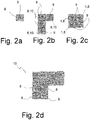
- the Fig. 2a shows in plan view a module 8, which has a module coil 9 represented by the stylized radio waves.
- the Fig. 2b shows a plan view of a driveway 10 of several modules 8 in operation as infrastructure modules in which along the right at the top end abbie ing route (route 10), the modules 8 successively activate the module coils 9 for power output when the route 10 from a truck. 2 is driven.
- the Fig. 2c shows in supervision several modules 8 in operation as composite modules.
- the module coils 9 are operated synchronously in order to achieve a larger area for the primary coil 1.
- the Fig. 2d shows in supervision several modules 8 in operation as composite modules as well as track modules.
- Each two modules 8, which are arranged side by side, are in operation as composite modules.
- a truck 2 can use the width of two modules for its secondary coil while the route 10 is traveled.
- the Fig. 4 shows in supervision modules 8 in operation as infrastructure modules.
- the modules 8 are connected to the adjoining this module 8 only via a cable connection 11.
Landscapes
- Engineering & Computer Science (AREA)
- Power Engineering (AREA)
- Mechanical Engineering (AREA)
- Transportation (AREA)
- Computer Networks & Wireless Communication (AREA)
- Charge And Discharge Circuits For Batteries Or The Like (AREA)
- Electric Propulsion And Braking For Vehicles (AREA)
Abstract
Description
- Die Erfindung betrifft eine Batterieladevorrichtung für ein Flurförderzeug. Insbesondere betrifft die Erfindung eine Batterieladevorrichtung für das induktive Laden einer Traktionsbatterie eines Flurförderzeugs mit einer Primärspule, die in einer von einem Flurförderzeug überfahrbaren Bodenfläche eingelassen ist, wobei die Primärspule aus einem oder mehreren, nebeneinander angeordneten Modulen mit jeweiligen Modulspulen aufgebaut ist, und die Primärspule elektrische Leistung an eine Sekundärspule des Flurförderzeugs übertragen kann.
- Bei Flurförderzeugen ist es üblich und Stand der Technik, dass Traktionsbatterien entweder bei einem Mehrschichtbetrieb zum Laden aus einem Batteriefach entnommen und gegen eine aufgeladene Traktionsbatterie ausgewechselt werden, oder der Fahrer gegen Ende seiner Arbeitsschicht ein Ladegerät über eine Steckerverbindung mit der Traktionsbatterie verbindet, um diese während der Arbeitspause aufzuladen. Typischerweise erfolgt dies pro Arbeitsschicht einmal, da eine Traktionsbatterie eines batterieelektrischen Flurförderzeugs im Regelfall so bemessen wird, dass mit einer Ladung der Traktionsbatterie eine komplette Arbeitsschicht gefahren und gearbeitet werden kann.
- Überdies ist es bei Blei-Säurebatterie anzustreben, diese mindestens bis zu einem gewissen Maß zu entladen, bevor ein Wiederaufladen erfolgt, da die Technologie dieser Batterien nicht für ein Zwischenladen geeignet ist und sich beispielsweise unerwünschte Memory-Effekte einstellen können.
- Durch neuere Technologien können inzwischen Batterien bzw. Akkumulatoren hergestellt werden und auch im industriellen Einsatz verwendet werden, die bessere Leistungsdaten bieten. Solche Batterien kann man als Hochleistungsbatterien bezeichnen, die sich dadurch auszeichnen, dass sie gegenüber einem Blei-Säureakkumulator eine höhere Energiedichte in Bezug auf Gewicht und/oder Volumen aufweisen und eine andere Technik als eine Blei-Säure Reaktion für die Energiespeicherung nutzen. Hinzu kommt bei vielen Hochleistungsbatterien als Merkmal, dass eine hohe Leistung beim Entladen abgegeben werden kann und/oder mit großer Leistung geladen werden kann. Die typischen Energiedichten in Bezug auf Gewicht und/oder Volumen liegen bei einer Hochleistungsbatterie dabei mindestens für einen der beiden Werte oberhalb und außerhalb der entsprechenden Kenngrößen für Blei-Säurebatterien.
- Zunehmend in größerem Umfang eingesetzt werden als Beispiel solcher Hochleistungsbatterien Lithium-Ionenbatterien, die sich durch hohe Energiedichte auszeichnen und nur einem geringen Memoryeffekt unterliegen sowie ein Entladen der Batterie bzw. Aufladen der Batterie mit großer Leistung ermöglichen.
- Besonders vorteilhaft ist der Einsatz solcher Hochleistungsbatterien bei Fahrzeugen und beispielsweise bei Flurförderzeugen, da aufgrund der hohen Energiedichte in Bezug auf das Volumen bei dem vorgegebenen Bauraum für die Traktionsbatterie eine größere Menge elektrische Energie gespeichert werden kann und somit die Reichweite eines Fahrzeugs bzw. die Einsatzdauer des Flurförderzeugs vergrößert werden kann. Insbesondere ist es jedoch möglich, solche Hochleistungsbatterie und vor allem Lithium-Ionenbatterien zwischenzuladen und somit kurze Arbeitspausen oder sonstige Möglichkeiten zum Wiederaufladen der Traktionsbatterie zu nutzen. Durch ein Zwischenladen wird es auch möglich, eine kleinere Kapazität für die Traktionsbatterie zu wählen und dadurch Kosten einzusparen.
- Für das Laden von Traktionsbatterien von Elektrofahrzeugen ist es bekannt, ein induktives Ladungssystem einzusetzen, bei dem eine Ladeeinheit über eine Primärspule mit einer Sekundärspule des Fahrzeugs induktiv koppelt und elektrische Leistung überträgt, die beispielsweise dazu dient, die Traktionsbatterie des Elektrofahrzeugs aufzuladen. Eine optimale Leistungsübertragung ist dann möglich, wenn die Primärspule und die Sekundärspule möglichst parallel ausgerichtet sind und einen möglichst kleinen Abstand aufweisen. Das Laden kann während des Stillstands des Elektrofahrzeugs an einer Ladestation geschehen, aber auch beispielsweise während der Fahrt, wenn Ladeeinheiten mit Primärspulen in der Fahrbahnfläche eingelassen sind.
- Als Problem erweist sich dabei eine flexible Anpassung der wirksamen und effektiven Größe der Primärspule. So kann es wünschenswert sein, eine große Querschnittsfläche der Primärspule zu erreichen mit einer entsprechend gleichgroßen Querschnittsfläche der Sekundärspule, um dadurch eine hohe Leistungsübertragung zu ermöglichen. Ebenso ist es vorteilhaft, eine möglichst große Querschnittsfläche der Primärspule zu erreichen, wenn die Querschnittsfläche der Sekundärspule deutlich kleiner ist, um auf diesem Weg die Positionierung zu erleichtern. Beispielsweise kann Rangieraufwand vermieden werden, wenn ein Flurförderzeug oder Elektrofahrzeug über einer Ladeeinheit mit einer in der Fahrbahnfläche angeordneten Primärspule abgestellt wird, solange die gesamte Querschnittsfläche der im Bodenbereich des Flurförderzeugs angeordneten Sekundärspule aufgrund der großen Querschnittsfläche der Primärspule überdeckt wird. Wenn ein Aufladen während einer Fahrt stattfinden soll, muss ein Fahrweg als Ladestation mit einer Primärspule überdeckt werden. Hier ist es wünschenswert, dass diese nicht die ganze Zeit aktiviert sein muss und daher anzustreben, die Primärspule in mehrere aufeinanderfolgende aufzuteilen. Dabei muss in Fahrtrichtung jeweils die nächste Primärspule aktiviert werden.
- Zur flexiblen Anpassung einer Ladestation und der Größe und Form der Primärspule ist es bekannt, Module einzusetzen, aus denen eine Gesamtfläche aus Primärspulen der Module zusammen gesetzt wird. Dies wird beispielsweise offenbart in der
DE 10 2013 015 424 A1 für im Boden angeordnete Primärspulen. - Der vorliegenden Erfindung liegt die Aufgabe zugrunde, eine Batterieladevorrichtung zur Verfügung zu stellen, bei der eine flexible Anpassung der Querschnittsfläche einer Primärspule durch die Verwendung von Modulen mit Spulen erfolgt und die oben genannten Nachteile vermieden werden, und das Verhalten der Ladevorrichtung an den Einsatz angepasst werden kann.
- Diese Aufgabe wird durch eine Batterieladevorrichtung für ein Flurförderzeug mit den Merkmalen des unabhängigen Patentanspruchs 1 gelöst. Vorteilhafte Weiterbildungen der Erfindung sind in den Unteransprüchen angegeben.
- Die Aufgabe wird erfindungsgemäß dadurch gelöst, dass bei einer Batterieladevorrichtung für das induktive Laden einer Traktionsbatterie eines Flurförderzeugs mit einer Primärspule, die in einer von einem Flurförderzeug überfahrbaren Bodenfläche eingelassen ist, wobei die Primärspule aus einem oder mehreren, nebeneinander angeordneten Modulen mit jeweiligen Modulspulen aufgebaut ist, und die Primärspule elektrische Leistung an eine Sekundärspule des Flurförderzeugs übertragen kann, jedes Modul für den Betrieb in Bezug auf ein festgelegtes benachbartes Modul auf einen Betrieb als Verbundmodul oder als Fahrwegmodul eingestellt werden kann, wobei im Betrieb als Verbundmodul die Modulspule mit dem benachbarten Modul synchron betrieben wird und im Betrieb als Fahrwegmodul von dem benachbarten Modul aktiviert wird, wenn dieses ein Flurförderzeug erfasst, oder umgekehrt das benachbarte Modul aktiviert, wenn durch das Modul selbst ein Flurförderzeug erfasst wird.
- Es ist durch diese erfindungsgemäße Lösung möglich, nahezu beliebige geometrische Formen für die Batterieladevorrichtung als im Boden eingelassene Primärspule zu bilden. Durch eine "intelligente" Vernetzung kann dabei festgelegt werden, welche Module insgesamt eine größere Fläche bilden, die synchron und zusammenwirkt, um beispielsweise eine größere Leistung auf eine entsprechende Sekundärspule zu übertragen oder aber auch das Positionieren eines Flurförderzeugs an einer Ladestation zu erleichtern. Es ist kein exaktes Ausrichten des Flurförderzeugs erforderlich, solang die Querschnittsfläche der Sekundärspule des Flurförderzeugs von einer Mehrzahl synchron arbeitender Modulspulen von Modulen im Betrieb als Verbundmodul überdeckt wird. Im Betrieb als Fahrwegmodul kann das Modul von dem benachbarten Modul eine Information erhalten, dass sich ein Flurförderzeug annähert. Es kann dann mit einer Verzögerung, aber auch bewusst bereits vorab eine Aktivierung der eigenen Modulspule erfolgen. Durch letzteres werden auftretende Latenzzeiten bei der Bereitstellung der elektrischen Ladeleistung minimiert. Mit denselben Modulen können somit auch Fahrwege gebildet werden, die als Batterieladevorrichtung dienen und mit denen ein Flurförderzeug während der Fahrt wieder aufgeladen werden kann. Dabei ist auch eine Kombination der Betriebsweise denkbar, beispielsweise dass je zwei nebeneinander angeordnete Module im Verbundbetrieb arbeiten und eine Fahrstraße mit einer Breite von zwei Modulen gebildet wird, so dass in der Richtung 90° zu den zwei Modulen die benachbarten wiederum zwei Module jeweils zueinander im Betrieb als Fahrwegmodule stehen.
- Vorteilhaft erfolgt die Einstellung über eine Kabelverbindung, wobei jedes Modul zwei Kabelanschlüsse aufweist und bei einer Verbindung mit einem benachbarten Modul über beide Kabelanschlüsse ein Betrieb als Verbundmodule festgelegt ist während bei einem Betrieb über einen Kabelanschluss ein Betrieb als Fahrwegmodule festgelegt ist.
- Das Modul kann quadratische Form haben und an allen vier Seiten je zwei Kabelanschlüsse aufweisen.
- Dies ermöglicht eine Festlegung der Betriebsweise beim Verlegen der Module im Boden und ist daher sehr effizient und intuitiv erfassbar durchzuführen.
- In einer günstigen Weiterbildung weist das Modul eine Steuerungsvorrichtung mit einem Bussystem auf, über die die Belegung der Kabelanschlüsse erfasst wird.
- Die Einstellung kann über einen Schalter an dem Modul erfolgen.
- Das Modul kann eine Steuerungsvorrichtung aufweisen und die Einstellung über einen Softwareparameter erfolgen.
- In vorteilhafter Ausführung erfasst das Modul im Betrieb als Fahrwegmodul über Sensoren ein Flurförderzeug.
- Als Sensor kann die Modulspule selbst dient, wenn durch diese Leistung abgegeben.
- Dabei kann beispielsweise durch das Ansteigen der abgegebenen Leistung eventuell auch die Geschwindigkeit des Flurförderzeugs eingeschätzt werden. Bei entsprechender Geometrie des Fahrweges kann aus dem Ansteigen der Leistung geschlossen werden, dass das Flurförderzeug als nächstes über das Modul selbst fahren wird und mit einer entsprechenden Regelung bzw. einer gewünschten Zeitdistanz die eigene Modulspule aktiviert werden.
- Es kann durch eine Steuerungsvorrichtung über eine Abfolge von Modulen im Betrieb als Fahrwegmodul eine Fahrtrichtung des Flurförderzeugs erfasst werden.
- Eine solche Steuerungsvorrichtung kann in jedem der Module vorhanden sein oder auch nur in einem zentral für mehrere. Diese Steuerungsvorrichtung kann aus der Abfolge der Leistungsabgabe der Module die Fahrtrichtung und eventuell die Fahrgeschwindigkeit des Flurförderzeugs erfassen. Abhängig davon kann die Aktivierung des nächstfolgenden Moduls erfolgen.
- Weitere Vorteile und Einzelheiten der Erfindung werden anhand der in den schematischen Figuren dargestellten Ausführungsbeispiele näher erläutert. Hierbei zeigt
- Fig. 1
- schematisch eine Batterieladevorrichtung mit einem darüber stehenden erfindungsgemäßen Flurförderzeug,
- Fig. 2a
- ein erfindungsgemäßes Modul in einer Draufsicht,
- Fig. 2b
- eine Draufsicht auf mehrere erfindungsgemäße, im Betrieb als Fahrwegmodule betriebene Module,
- Fig. 2c
- eine Draufsicht auf mehrere erfindungsgemäße, im Betrieb als Verbundmodule betriebene Module,
- Fig. 2d
- eine Draufsicht auf mehrere erfindungsgemäße, im Betrieb als Verbundmodule wie auch als Fahrwegmodule betriebene Module,
- Fig. 3
- eine Draufsicht auf mehrere erfindungsgemäße Module im Betrieb als Verbundmodule und
- Fig. 4
- eine Draufsicht auf mehrere erfindungsgemäße Module im Betrieb als Fahrwegmodule.
- Die
Fig. 1 zeigt schematisch eine Batterieladevorrichtung 1 mit einem darüber stehenden erfindungsgemäßen Flurförderzeug 2. Die in eine Fahrbahn 7 eingelassene Batterieladevorrichtung 1 weist eine Primärspule 3 auf, während das Flurförderzeug 2 an der Unterseite angeordnet eine entsprechende Sekundärspule 4 zwischen einer Vorderachse 5 und eine Hinterachse 6 aufweist. Von der Primärspule 3 wird induktiv in die Sekundärspule 4 des Flurförderzeugs 2 elektrische Energie übertragen, um beispielsweise eine Traktionsbatterie des Flurförderzeugs 2 aufzuladen. - Die
Fig. 2a zeigt in Aufsicht ein Modul 8, das eine durch die stilisierten Funkwellen dargestellte Modulspule 9 aufweist. - Die
Fig. 2b zeigt in Aufsicht eine Fahrstraße 10 aus mehreren Modulen 8 im Betrieb als Fahrwegmodule, bei denen entlang der nach rechts am oberen Ende abbie genden Strecke (Fahrstraße 10) die Module 8 nacheinander die Modulspulen 9 zur Leistungsabgabe aktivieren, wenn die Fahrstraße 10 von einem Flurförderzeug 2 befahren wird. - Die
Fig. 2c zeigt in Aufsicht mehrere Module 8 im Betrieb als Verbundmodule. Dabei werden die Modulspulen 9 synchron betrieben, um eine größere Fläche für die Primärspule 1 zu erreichen. - Die
Fig. 2d zeigt in Aufsicht mehrere Module 8 im Betrieb als Verbundmodule wie auch als Fahrwegmodule. Je zwei Module 8, die nebeneinander angeordnet sind, befinden sich im Betrieb als Verbundmodule. Mit den darüber angeordneten zwei Modulen 8 bzw. entlang der nach rechts abbiegenden Fahrstraße 10 besteht jeweils eine Verbindung für einen Betrieb als Fahrwegmodule. Somit kann ein Flurförderzeug 2 die Breite von zwei Modulen für seine Sekundärspule nutzen während die Fahrstraße 10 befahren wird. - Die
Fig. 3 zeigt in Aufsicht Module 8 im Betrieb als Verbundmodule. An allen vier Seiten des jeweiligen Moduls 8 bestehen jeweils zwei Kabelanschlüsse 11, die durch die Pfeile dargestellt sind. In dem vorliegenden Beispiel sind die vier benachbart angeordneten Module 8 mit jedem anliegenden Modul 8 über je beide Kabelanschlüsse 11 verbunden, so das alle vier Module 8 als Verbundmodule betrieben werden. - Die
Fig. 4 zeigt in Aufsicht Module 8 im Betrieb als Fahrwegmodule. Die Module 8 sind mit dem jeweils an dieses anstoßenden Modul 8 nur über einen Kabelanschluss 11 verbunden.
Claims (9)
- Batterieladevorrichtung für das induktive Laden einer Traktionsbatterie eines Flurförderzeugs mit einer Primärspule (1), die in einer von einem Flurförderzeug (2) überfahrbaren Bodenfläche (7) eingelassen ist, wobei die Primärspule (1) aus einem oder mehreren, nebeneinander angeordneten Modulen (8) mit jeweiligen Modulspulen (9) aufgebaut ist, und die Primärspule (1) elektrische Leistung an eine Sekundärspule (4) des Flurförderzeugs (2) übertragen kann,
dadurch gekennzeichnet,
dass jedes Modul (8) für den Betrieb in Bezug auf ein festgelegtes benachbartes Modul (8) auf einen Betrieb als Verbundmodul oder als Fahrwegmodul eingestellt werden kann, wobei im Betrieb als Verbundmodul die Modulspule (9) mit dem benachbarten Modul (8) synchron betrieben wird und im Betrieb als Fahrwegmodul von dem benachbarten Modul (8) aktiviert wird, wenn dieses ein Flurförderzeug (2) erfasst, oder umgekehrt das benachbarte Modul (8) aktiviert, wenn durch das Modul (8) selbst ein Flurförderzeug (2) erfasst wird. - Batterieladevorrichtung nach Anspruch 1,
dadurch gekennzeichnet,
dass die Einstellung über eine Kabelverbindung erfolgt, wobei jedes Modul (8) zwei Kabelanschlüsse (11) aufweist und bei einer Verbindung mit einem benachbarten Modul (8) über beide Kabelanschlüsse (11) ein Betrieb als Verbundmodule festgelegt ist während bei einem Betrieb über einen Kabelanschluss (11) ein Betrieb als Fahrwegmodule festgelegt ist. - Batterieladevorrichtung nach Anspruch 2,
dadurch gekennzeichnet,
dass das Modul (8) quadratische Form hat und an allen vier Seiten zwei Kabelanschlüsse (11) aufweist. - Batterieladevorrichtung nach einem der Ansprüche 2 oder 3,
dadurch gekennzeichnet,
dass das Modul (8) eine Steuerungsvorrichtung mit einem Bussystem aufweist, über die die Belegung der Kabelanschlüsse (11) erfasst wird. - Batterieladevorrichtung nach einem der Ansprüche 1 bis 4,
dadurch gekennzeichnet,
dass die Einstellung über einen Schalter an dem Modul (8) erfolgt. - Batterieladevorrichtung nach einem der Ansprüche 1 bis 5,
dadurch gekennzeichnet,
dass das Modul (8) eine Steuerungsvorrichtung aufweist und die Einstellung über einen Softwareparameter erfolgt. - Batterieladevorrichtung nach einem der Ansprüche 1 bis 5,
dadurch gekennzeichnet,
dass das Modul (8) im Betrieb als Fahrwegmodul über Sensoren ein Flurförderzeug (2) erfasst. - Batterieladevorrichtung nach Anspruch 7,
dadurch gekennzeichnet,
dass als Sensor die Modulspule (9) selbst dient, wenn durch diese Leistung abgegeben wird. - Batterieladevorrichtung nach Anspruch 7 oder 8,
dadurch gekennzeichnet,
dass durch eine Steuerungsvorrichtung über eine Abfolge von Modulen (8) im Betrieb als Fahrwegmodul eine Fahrtrichtung des Flurförderzeugs erfasst wird.
Applications Claiming Priority (2)
| Application Number | Priority Date | Filing Date | Title |
|---|---|---|---|
| DE102015122905 | 2015-12-29 | ||
| DE102016119677.0A DE102016119677A1 (de) | 2015-12-29 | 2016-10-14 | Batterieladevorrichtung für Flurförderzeug |
Publications (2)
| Publication Number | Publication Date |
|---|---|
| EP3187362A1 true EP3187362A1 (de) | 2017-07-05 |
| EP3187362B1 EP3187362B1 (de) | 2020-05-06 |
Family
ID=57240843
Family Applications (1)
| Application Number | Title | Priority Date | Filing Date |
|---|---|---|---|
| EP16195324.5A Active EP3187362B1 (de) | 2015-12-29 | 2016-10-24 | Batterieladevorrichtung für flurförderzeug |
Country Status (1)
| Country | Link |
|---|---|
| EP (1) | EP3187362B1 (de) |
Cited By (2)
| Publication number | Priority date | Publication date | Assignee | Title |
|---|---|---|---|---|
| WO2019161921A1 (de) * | 2018-02-23 | 2019-08-29 | Industrieanlagen-Betriebsgesellschaft Mbh | Vorrichtung zum erzeugen eines magnetfelds, insbesondere für ein induktives ladesystem, und primäreinrichtung eines induktiven ladesystems zum dynamischen aufladen von fahrzeugen |
| EP3756932A1 (de) | 2019-06-25 | 2020-12-30 | Taccad Engineering GmbH | System zum induktiven laden elektrischer batterien in einem strassenfahrzeug |
Citations (5)
| Publication number | Priority date | Publication date | Assignee | Title |
|---|---|---|---|---|
| US20090045773A1 (en) * | 2007-08-13 | 2009-02-19 | Pandya Ravi A | Wireless Charging System for Vehicles |
| US20120119575A1 (en) * | 2008-09-27 | 2012-05-17 | Kurs Andre B | Wireless energy transfer for vehicles |
| US20120256586A1 (en) * | 2009-12-09 | 2012-10-11 | Becker Guenter | System for the Inductive Charging of an Energy Accumulator of a Vehicle, and Charging Station |
| DE102013015424A1 (de) | 2013-09-18 | 2015-03-19 | Sew-Eurodrive Gmbh & Co Kg | Modul und System zur berührungslosen Energieübertragung mit einem oder mehreren Modulen |
| US20150298559A1 (en) * | 2014-04-18 | 2015-10-22 | Qualcomm Incorporated | Base distribution network for dynamic wireless charging |
-
2016
- 2016-10-24 EP EP16195324.5A patent/EP3187362B1/de active Active
Patent Citations (5)
| Publication number | Priority date | Publication date | Assignee | Title |
|---|---|---|---|---|
| US20090045773A1 (en) * | 2007-08-13 | 2009-02-19 | Pandya Ravi A | Wireless Charging System for Vehicles |
| US20120119575A1 (en) * | 2008-09-27 | 2012-05-17 | Kurs Andre B | Wireless energy transfer for vehicles |
| US20120256586A1 (en) * | 2009-12-09 | 2012-10-11 | Becker Guenter | System for the Inductive Charging of an Energy Accumulator of a Vehicle, and Charging Station |
| DE102013015424A1 (de) | 2013-09-18 | 2015-03-19 | Sew-Eurodrive Gmbh & Co Kg | Modul und System zur berührungslosen Energieübertragung mit einem oder mehreren Modulen |
| US20150298559A1 (en) * | 2014-04-18 | 2015-10-22 | Qualcomm Incorporated | Base distribution network for dynamic wireless charging |
Cited By (4)
| Publication number | Priority date | Publication date | Assignee | Title |
|---|---|---|---|---|
| WO2019161921A1 (de) * | 2018-02-23 | 2019-08-29 | Industrieanlagen-Betriebsgesellschaft Mbh | Vorrichtung zum erzeugen eines magnetfelds, insbesondere für ein induktives ladesystem, und primäreinrichtung eines induktiven ladesystems zum dynamischen aufladen von fahrzeugen |
| CN111801245A (zh) * | 2018-02-23 | 2020-10-20 | 工业设备运营公司 | 产生磁场的设备,特别是为感应式充电系统产生磁场的设备,以及对交通工具动态充电的感应式充电系统的初级装置 |
| CN111801245B (zh) * | 2018-02-23 | 2024-04-30 | 工业设备运营公司 | 产生磁场的设备以及对交通工具动态充电的感应式充电系统的初级装置 |
| EP3756932A1 (de) | 2019-06-25 | 2020-12-30 | Taccad Engineering GmbH | System zum induktiven laden elektrischer batterien in einem strassenfahrzeug |
Also Published As
| Publication number | Publication date |
|---|---|
| EP3187362B1 (de) | 2020-05-06 |
Similar Documents
| Publication | Publication Date | Title |
|---|---|---|
| EP3546278A1 (de) | Laderoboter und verfahren zu dessen betrieb | |
| DE102014109430A1 (de) | Energiespeichersystem und Verfahren zum Betrieb eines Energiespeichersystems | |
| DE102016111682A1 (de) | Fahrzeugladesystem | |
| DE102009013694A1 (de) | Energieübertragungssystem mit mehreren Primärspulen | |
| WO2012079668A2 (de) | Kraftfahrzeugvorrichtung mit einer lade- und/oder entladeeinheit | |
| DE102012003309A1 (de) | Elektrisches Energiesystem in einem Kraftfahrzeug und Verfahren zum Betreiben eines Energiesystems | |
| EP2647100A2 (de) | Vorrichtung zur verwendung in einem elektrischen antriebssystem und verfahren zum betrieb einer solchen | |
| DE102018129905A1 (de) | Verfahren zur Nutzung zumindest einer Ladeeinheit, Fahrzeug, Ladeeinheit, sowie Transportsystem | |
| EP3305574B1 (de) | Verfahren zum betrieb einer achse einer strassenfahrzeug-zugkombination | |
| DE102016119677A1 (de) | Batterieladevorrichtung für Flurförderzeug | |
| WO2019001915A1 (de) | Antriebsstrang sowie verfahren zum betreiben eines antriebsstrangs | |
| DE102011104443A1 (de) | Verfahren zum Betrieb eines Hybridfahrzeugs | |
| DE102012006836A1 (de) | Kombinierte Abstell- und Aufladeeinrichtung für ein Elektro- oder Hybridfahrzeug | |
| EP3545537A1 (de) | Induktives bauelement und sekundärresonatoreinrichtung zur montage an einem elektrokraftfahrzeug | |
| DE102017212894A1 (de) | Vorrichtung zum Laden | |
| EP3187362B1 (de) | Batterieladevorrichtung für flurförderzeug | |
| EP4056413B1 (de) | Batterieladevorrichtung für induktives laden, insbesondere dynamisches und/oder stationäres induktives laden, einer traktionsbatterie eines fahrzeugs | |
| WO2020039053A1 (de) | Wohnwagen | |
| DE102020006921A1 (de) | Fahrradanhänger mit Sekundärstromversorgung | |
| EP3187455B1 (de) | System aus flurförderzeug und batterieladevorrichtung | |
| DE102017205229B4 (de) | Energieübertragungsvorrichtung zur kapazitiven Energieübertragung, Kraftfahrzeug mit einem fahrzeugseitigen Übertragungsteil, Ladestation mit einem stationären Übertragungsteil sowie ein Verfahren zum Betreiben der Energieübertragungsvorrichtung | |
| DE102014205418A1 (de) | Induktives Auf- und Entladen von Akkumulatoren | |
| DE112019004903T5 (de) | Verfahren und Steuervorrichtung zum Steuern von Energiepegeln von Energiespeichervorrichtungen in einem Fahrzeug | |
| DE102019002773A1 (de) | Batterietransportwagen für einen elektrisch betreibbaren Kraftwagen; Ladevorrichtung sowie Verfahren zum Versorgen eines Kraftwagens mit elektrischer Energie | |
| WO2018104539A1 (de) | Kraftfahrzeug |
Legal Events
| Date | Code | Title | Description |
|---|---|---|---|
| PUAI | Public reference made under article 153(3) epc to a published international application that has entered the european phase |
Free format text: ORIGINAL CODE: 0009012 |
|
| STAA | Information on the status of an ep patent application or granted ep patent |
Free format text: STATUS: THE APPLICATION HAS BEEN PUBLISHED |
|
| AK | Designated contracting states |
Kind code of ref document: A1 Designated state(s): AL AT BE BG CH CY CZ DE DK EE ES FI FR GB GR HR HU IE IS IT LI LT LU LV MC MK MT NL NO PL PT RO RS SE SI SK SM TR |
|
| AX | Request for extension of the european patent |
Extension state: BA ME |
|
| STAA | Information on the status of an ep patent application or granted ep patent |
Free format text: STATUS: REQUEST FOR EXAMINATION WAS MADE |
|
| 17P | Request for examination filed |
Effective date: 20171228 |
|
| RBV | Designated contracting states (corrected) |
Designated state(s): AL AT BE BG CH CY CZ DE DK EE ES FI FR GB GR HR HU IE IS IT LI LT LU LV MC MK MT NL NO PL PT RO RS SE SI SK SM TR |
|
| STAA | Information on the status of an ep patent application or granted ep patent |
Free format text: STATUS: EXAMINATION IS IN PROGRESS |
|
| 17Q | First examination report despatched |
Effective date: 20190408 |
|
| REG | Reference to a national code |
Ref country code: DE Ref legal event code: R079 Ref document number: 502016009837 Country of ref document: DE Free format text: PREVIOUS MAIN CLASS: B60L0011180000 Ipc: H02J0007020000 |
|
| RIC1 | Information provided on ipc code assigned before grant |
Ipc: B60L 5/00 20060101ALI20191211BHEP Ipc: B60L 53/30 20190101ALI20191211BHEP Ipc: H02J 7/02 20160101AFI20191211BHEP Ipc: H02J 7/00 20060101ALI20191211BHEP Ipc: H02J 50/90 20160101ALI20191211BHEP Ipc: B60M 7/00 20060101ALI20191211BHEP Ipc: H02J 50/40 20160101ALI20191211BHEP Ipc: H02J 50/10 20160101ALI20191211BHEP Ipc: B60L 53/39 20190101ALI20191211BHEP Ipc: H02J 5/00 20160101ALI20191211BHEP Ipc: B60L 53/12 20190101ALI20191211BHEP |
|
| GRAP | Despatch of communication of intention to grant a patent |
Free format text: ORIGINAL CODE: EPIDOSNIGR1 |
|
| STAA | Information on the status of an ep patent application or granted ep patent |
Free format text: STATUS: GRANT OF PATENT IS INTENDED |
|
| INTG | Intention to grant announced |
Effective date: 20200127 |
|
| GRAS | Grant fee paid |
Free format text: ORIGINAL CODE: EPIDOSNIGR3 |
|
| GRAA | (expected) grant |
Free format text: ORIGINAL CODE: 0009210 |
|
| STAA | Information on the status of an ep patent application or granted ep patent |
Free format text: STATUS: THE PATENT HAS BEEN GRANTED |
|
| AK | Designated contracting states |
Kind code of ref document: B1 Designated state(s): AL AT BE BG CH CY CZ DE DK EE ES FI FR GB GR HR HU IE IS IT LI LT LU LV MC MK MT NL NO PL PT RO RS SE SI SK SM TR |
|
| REG | Reference to a national code |
Ref country code: GB Ref legal event code: FG4D Free format text: NOT ENGLISH |
|
| REG | Reference to a national code |
Ref country code: CH Ref legal event code: EP Ref country code: AT Ref legal event code: REF Ref document number: 1268389 Country of ref document: AT Kind code of ref document: T Effective date: 20200515 |
|
| REG | Reference to a national code |
Ref country code: IE Ref legal event code: FG4D Free format text: LANGUAGE OF EP DOCUMENT: GERMAN |
|
| REG | Reference to a national code |
Ref country code: DE Ref legal event code: R096 Ref document number: 502016009837 Country of ref document: DE |
|
| REG | Reference to a national code |
Ref country code: LT Ref legal event code: MG4D |
|
| REG | Reference to a national code |
Ref country code: NL Ref legal event code: MP Effective date: 20200506 |
|
| PG25 | Lapsed in a contracting state [announced via postgrant information from national office to epo] |
Ref country code: GR Free format text: LAPSE BECAUSE OF FAILURE TO SUBMIT A TRANSLATION OF THE DESCRIPTION OR TO PAY THE FEE WITHIN THE PRESCRIBED TIME-LIMIT Effective date: 20200807 Ref country code: NO Free format text: LAPSE BECAUSE OF FAILURE TO SUBMIT A TRANSLATION OF THE DESCRIPTION OR TO PAY THE FEE WITHIN THE PRESCRIBED TIME-LIMIT Effective date: 20200806 Ref country code: LT Free format text: LAPSE BECAUSE OF FAILURE TO SUBMIT A TRANSLATION OF THE DESCRIPTION OR TO PAY THE FEE WITHIN THE PRESCRIBED TIME-LIMIT Effective date: 20200506 Ref country code: IS Free format text: LAPSE BECAUSE OF FAILURE TO SUBMIT A TRANSLATION OF THE DESCRIPTION OR TO PAY THE FEE WITHIN THE PRESCRIBED TIME-LIMIT Effective date: 20200906 Ref country code: PT Free format text: LAPSE BECAUSE OF FAILURE TO SUBMIT A TRANSLATION OF THE DESCRIPTION OR TO PAY THE FEE WITHIN THE PRESCRIBED TIME-LIMIT Effective date: 20200907 Ref country code: SE Free format text: LAPSE BECAUSE OF FAILURE TO SUBMIT A TRANSLATION OF THE DESCRIPTION OR TO PAY THE FEE WITHIN THE PRESCRIBED TIME-LIMIT Effective date: 20200506 Ref country code: FI Free format text: LAPSE BECAUSE OF FAILURE TO SUBMIT A TRANSLATION OF THE DESCRIPTION OR TO PAY THE FEE WITHIN THE PRESCRIBED TIME-LIMIT Effective date: 20200506 |
|
| PG25 | Lapsed in a contracting state [announced via postgrant information from national office to epo] |
Ref country code: HR Free format text: LAPSE BECAUSE OF FAILURE TO SUBMIT A TRANSLATION OF THE DESCRIPTION OR TO PAY THE FEE WITHIN THE PRESCRIBED TIME-LIMIT Effective date: 20200506 Ref country code: RS Free format text: LAPSE BECAUSE OF FAILURE TO SUBMIT A TRANSLATION OF THE DESCRIPTION OR TO PAY THE FEE WITHIN THE PRESCRIBED TIME-LIMIT Effective date: 20200506 Ref country code: BG Free format text: LAPSE BECAUSE OF FAILURE TO SUBMIT A TRANSLATION OF THE DESCRIPTION OR TO PAY THE FEE WITHIN THE PRESCRIBED TIME-LIMIT Effective date: 20200806 Ref country code: LV Free format text: LAPSE BECAUSE OF FAILURE TO SUBMIT A TRANSLATION OF THE DESCRIPTION OR TO PAY THE FEE WITHIN THE PRESCRIBED TIME-LIMIT Effective date: 20200506 |
|
| PG25 | Lapsed in a contracting state [announced via postgrant information from national office to epo] |
Ref country code: NL Free format text: LAPSE BECAUSE OF FAILURE TO SUBMIT A TRANSLATION OF THE DESCRIPTION OR TO PAY THE FEE WITHIN THE PRESCRIBED TIME-LIMIT Effective date: 20200506 Ref country code: AL Free format text: LAPSE BECAUSE OF FAILURE TO SUBMIT A TRANSLATION OF THE DESCRIPTION OR TO PAY THE FEE WITHIN THE PRESCRIBED TIME-LIMIT Effective date: 20200506 |
|
| PG25 | Lapsed in a contracting state [announced via postgrant information from national office to epo] |
Ref country code: IT Free format text: LAPSE BECAUSE OF FAILURE TO SUBMIT A TRANSLATION OF THE DESCRIPTION OR TO PAY THE FEE WITHIN THE PRESCRIBED TIME-LIMIT Effective date: 20200506 Ref country code: DK Free format text: LAPSE BECAUSE OF FAILURE TO SUBMIT A TRANSLATION OF THE DESCRIPTION OR TO PAY THE FEE WITHIN THE PRESCRIBED TIME-LIMIT Effective date: 20200506 Ref country code: SM Free format text: LAPSE BECAUSE OF FAILURE TO SUBMIT A TRANSLATION OF THE DESCRIPTION OR TO PAY THE FEE WITHIN THE PRESCRIBED TIME-LIMIT Effective date: 20200506 Ref country code: EE Free format text: LAPSE BECAUSE OF FAILURE TO SUBMIT A TRANSLATION OF THE DESCRIPTION OR TO PAY THE FEE WITHIN THE PRESCRIBED TIME-LIMIT Effective date: 20200506 Ref country code: RO Free format text: LAPSE BECAUSE OF FAILURE TO SUBMIT A TRANSLATION OF THE DESCRIPTION OR TO PAY THE FEE WITHIN THE PRESCRIBED TIME-LIMIT Effective date: 20200506 Ref country code: ES Free format text: LAPSE BECAUSE OF FAILURE TO SUBMIT A TRANSLATION OF THE DESCRIPTION OR TO PAY THE FEE WITHIN THE PRESCRIBED TIME-LIMIT Effective date: 20200506 Ref country code: CZ Free format text: LAPSE BECAUSE OF FAILURE TO SUBMIT A TRANSLATION OF THE DESCRIPTION OR TO PAY THE FEE WITHIN THE PRESCRIBED TIME-LIMIT Effective date: 20200506 |
|
| REG | Reference to a national code |
Ref country code: DE Ref legal event code: R097 Ref document number: 502016009837 Country of ref document: DE |
|
| PG25 | Lapsed in a contracting state [announced via postgrant information from national office to epo] |
Ref country code: SK Free format text: LAPSE BECAUSE OF FAILURE TO SUBMIT A TRANSLATION OF THE DESCRIPTION OR TO PAY THE FEE WITHIN THE PRESCRIBED TIME-LIMIT Effective date: 20200506 Ref country code: PL Free format text: LAPSE BECAUSE OF FAILURE TO SUBMIT A TRANSLATION OF THE DESCRIPTION OR TO PAY THE FEE WITHIN THE PRESCRIBED TIME-LIMIT Effective date: 20200506 |
|
| PLBE | No opposition filed within time limit |
Free format text: ORIGINAL CODE: 0009261 |
|
| STAA | Information on the status of an ep patent application or granted ep patent |
Free format text: STATUS: NO OPPOSITION FILED WITHIN TIME LIMIT |
|
| 26N | No opposition filed |
Effective date: 20210209 |
|
| PG25 | Lapsed in a contracting state [announced via postgrant information from national office to epo] |
Ref country code: SI Free format text: LAPSE BECAUSE OF FAILURE TO SUBMIT A TRANSLATION OF THE DESCRIPTION OR TO PAY THE FEE WITHIN THE PRESCRIBED TIME-LIMIT Effective date: 20200506 |
|
| REG | Reference to a national code |
Ref country code: CH Ref legal event code: PL |
|
| PG25 | Lapsed in a contracting state [announced via postgrant information from national office to epo] |
Ref country code: LU Free format text: LAPSE BECAUSE OF NON-PAYMENT OF DUE FEES Effective date: 20201024 Ref country code: MC Free format text: LAPSE BECAUSE OF FAILURE TO SUBMIT A TRANSLATION OF THE DESCRIPTION OR TO PAY THE FEE WITHIN THE PRESCRIBED TIME-LIMIT Effective date: 20200506 |
|
| REG | Reference to a national code |
Ref country code: BE Ref legal event code: MM Effective date: 20201031 |
|
| PG25 | Lapsed in a contracting state [announced via postgrant information from national office to epo] |
Ref country code: LI Free format text: LAPSE BECAUSE OF NON-PAYMENT OF DUE FEES Effective date: 20201031 Ref country code: CH Free format text: LAPSE BECAUSE OF NON-PAYMENT OF DUE FEES Effective date: 20201031 Ref country code: BE Free format text: LAPSE BECAUSE OF NON-PAYMENT OF DUE FEES Effective date: 20201031 |
|
| PG25 | Lapsed in a contracting state [announced via postgrant information from national office to epo] |
Ref country code: IE Free format text: LAPSE BECAUSE OF NON-PAYMENT OF DUE FEES Effective date: 20201024 |
|
| PG25 | Lapsed in a contracting state [announced via postgrant information from national office to epo] |
Ref country code: TR Free format text: LAPSE BECAUSE OF FAILURE TO SUBMIT A TRANSLATION OF THE DESCRIPTION OR TO PAY THE FEE WITHIN THE PRESCRIBED TIME-LIMIT Effective date: 20200506 Ref country code: MT Free format text: LAPSE BECAUSE OF FAILURE TO SUBMIT A TRANSLATION OF THE DESCRIPTION OR TO PAY THE FEE WITHIN THE PRESCRIBED TIME-LIMIT Effective date: 20200506 Ref country code: CY Free format text: LAPSE BECAUSE OF FAILURE TO SUBMIT A TRANSLATION OF THE DESCRIPTION OR TO PAY THE FEE WITHIN THE PRESCRIBED TIME-LIMIT Effective date: 20200506 |
|
| PG25 | Lapsed in a contracting state [announced via postgrant information from national office to epo] |
Ref country code: MK Free format text: LAPSE BECAUSE OF FAILURE TO SUBMIT A TRANSLATION OF THE DESCRIPTION OR TO PAY THE FEE WITHIN THE PRESCRIBED TIME-LIMIT Effective date: 20200506 |
|
| REG | Reference to a national code |
Ref country code: AT Ref legal event code: MM01 Ref document number: 1268389 Country of ref document: AT Kind code of ref document: T Effective date: 20211024 |
|
| PG25 | Lapsed in a contracting state [announced via postgrant information from national office to epo] |
Ref country code: AT Free format text: LAPSE BECAUSE OF NON-PAYMENT OF DUE FEES Effective date: 20211024 |
|
| P01 | Opt-out of the competence of the unified patent court (upc) registered |
Effective date: 20230518 |
|
| PGFP | Annual fee paid to national office [announced via postgrant information from national office to epo] |
Ref country code: GB Payment date: 20231025 Year of fee payment: 8 |
|
| PGFP | Annual fee paid to national office [announced via postgrant information from national office to epo] |
Ref country code: FR Payment date: 20231023 Year of fee payment: 8 |
|
| GBPC | Gb: european patent ceased through non-payment of renewal fee |
Effective date: 20241024 |
|
| PG25 | Lapsed in a contracting state [announced via postgrant information from national office to epo] |
Ref country code: GB Free format text: LAPSE BECAUSE OF NON-PAYMENT OF DUE FEES Effective date: 20241024 |
|
| PG25 | Lapsed in a contracting state [announced via postgrant information from national office to epo] |
Ref country code: FR Free format text: LAPSE BECAUSE OF NON-PAYMENT OF DUE FEES Effective date: 20241031 |
|
| PGFP | Annual fee paid to national office [announced via postgrant information from national office to epo] |
Ref country code: DE Payment date: 20251020 Year of fee payment: 10 |