EP3185405A1 - Moteur electrique - Google Patents
Moteur electrique Download PDFInfo
- Publication number
- EP3185405A1 EP3185405A1 EP15202549.0A EP15202549A EP3185405A1 EP 3185405 A1 EP3185405 A1 EP 3185405A1 EP 15202549 A EP15202549 A EP 15202549A EP 3185405 A1 EP3185405 A1 EP 3185405A1
- Authority
- EP
- European Patent Office
- Prior art keywords
- winding
- stator
- electric motor
- stator core
- motor according
- Prior art date
- Legal status (The legal status is an assumption and is not a legal conclusion. Google has not performed a legal analysis and makes no representation as to the accuracy of the status listed.)
- Granted
Links
- 238000004804 winding Methods 0.000 claims abstract description 121
- 230000008878 coupling Effects 0.000 claims abstract description 19
- 238000010168 coupling process Methods 0.000 claims abstract description 19
- 238000005859 coupling reaction Methods 0.000 claims abstract description 19
- 239000002184 metal Substances 0.000 claims description 21
- 238000009413 insulation Methods 0.000 claims description 20
- 238000000034 method Methods 0.000 claims description 13
- 238000004519 manufacturing process Methods 0.000 claims description 10
- 238000001816 cooling Methods 0.000 claims description 8
- 238000010438 heat treatment Methods 0.000 claims description 6
- 238000003780 insertion Methods 0.000 abstract description 3
- 230000037431 insertion Effects 0.000 abstract description 3
- 230000004323 axial length Effects 0.000 description 8
- 238000005516 engineering process Methods 0.000 description 4
- 238000011161 development Methods 0.000 description 3
- 230000018109 developmental process Effects 0.000 description 3
- 230000000694 effects Effects 0.000 description 3
- 239000002966 varnish Substances 0.000 description 3
- 238000006073 displacement reaction Methods 0.000 description 2
- 238000010292 electrical insulation Methods 0.000 description 2
- 230000001965 increasing effect Effects 0.000 description 2
- 239000000463 material Substances 0.000 description 2
- 230000003071 parasitic effect Effects 0.000 description 2
- 238000003825 pressing Methods 0.000 description 2
- 238000005096 rolling process Methods 0.000 description 2
- 210000002105 tongue Anatomy 0.000 description 2
- 238000012549 training Methods 0.000 description 2
- 238000005452 bending Methods 0.000 description 1
- 230000006835 compression Effects 0.000 description 1
- 238000007906 compression Methods 0.000 description 1
- 238000002788 crimping Methods 0.000 description 1
- 230000007423 decrease Effects 0.000 description 1
- 230000001419 dependent effect Effects 0.000 description 1
- 238000013461 design Methods 0.000 description 1
- 238000010586 diagram Methods 0.000 description 1
- 239000000945 filler Substances 0.000 description 1
- 238000010348 incorporation Methods 0.000 description 1
- 230000001939 inductive effect Effects 0.000 description 1
- 238000003475 lamination Methods 0.000 description 1
- 239000003973 paint Substances 0.000 description 1
- 230000002028 premature Effects 0.000 description 1
- 238000011144 upstream manufacturing Methods 0.000 description 1
Images


Classifications
-
- H—ELECTRICITY
- H02—GENERATION; CONVERSION OR DISTRIBUTION OF ELECTRIC POWER
- H02K—DYNAMO-ELECTRIC MACHINES
- H02K15/00—Methods or apparatus specially adapted for manufacturing, assembling, maintaining or repairing of dynamo-electric machines
- H02K15/0025—Shaping or compacting conductors or winding heads after the installation of the winding in the core or machine ; Applying fastening means on winding heads
- H02K15/0031—Shaping or compacting conductors in slots or around salient poles
-
- H—ELECTRICITY
- H02—GENERATION; CONVERSION OR DISTRIBUTION OF ELECTRIC POWER
- H02K—DYNAMO-ELECTRIC MACHINES
- H02K3/00—Details of windings
- H02K3/32—Windings characterised by the shape, form or construction of the insulation
- H02K3/34—Windings characterised by the shape, form or construction of the insulation between conductors or between conductor and core, e.g. slot insulation
- H02K3/345—Windings characterised by the shape, form or construction of the insulation between conductors or between conductor and core, e.g. slot insulation between conductor and core, e.g. slot insulation
-
- H—ELECTRICITY
- H02—GENERATION; CONVERSION OR DISTRIBUTION OF ELECTRIC POWER
- H02K—DYNAMO-ELECTRIC MACHINES
- H02K3/00—Details of windings
- H02K3/32—Windings characterised by the shape, form or construction of the insulation
- H02K3/38—Windings characterised by the shape, form or construction of the insulation around winding heads, equalising connectors, or connections thereto
-
- H—ELECTRICITY
- H02—GENERATION; CONVERSION OR DISTRIBUTION OF ELECTRIC POWER
- H02K—DYNAMO-ELECTRIC MACHINES
- H02K3/00—Details of windings
- H02K3/42—Means for preventing or reducing eddy-current losses in the winding heads, e.g. by shielding
-
- H—ELECTRICITY
- H02—GENERATION; CONVERSION OR DISTRIBUTION OF ELECTRIC POWER
- H02K—DYNAMO-ELECTRIC MACHINES
- H02K2213/00—Specific aspects, not otherwise provided for and not covered by codes H02K2201/00 - H02K2211/00
- H02K2213/03—Machines characterised by numerical values, ranges, mathematical expressions or similar information
Definitions
- the invention relates to an electric motor with a stator and a rotor rotatably mounted therein, which is suitable for operation with a frequency converter.
- frequency converters which first convert the alternating or three-phase current into a direct current, in order then to convert it by means of electronic switches into a current of the desired amplitude and frequency.
- the alternating currents generated by the frequency converter correspond to the desired specifications in terms of amplitude and frequency, they are not pure sine-wave, but are subject to high-frequency harmonics due to the fast switching processes by which the respective signal is generated.
- These high-frequency signal components first pass through the capacitive coupling from the stator into the rotor from there into the motor housing.
- the invention has the object, an electric motor in such a way that even when controlled by a frequency converter or other electronic speed controller no increased bearing load occurs by such high-frequency currents.
- the electric motor according to the invention has a stator and a rotatably mounted rotor therein.
- the stator has a stator core with stator slots, in which stator windings are accommodated, which have winding heads which extend at the end and outside of the slots.
- Winding head shields are arranged between the winding heads and the rotor, wherein the stator slots each have a gap which is open to the rotor and has no winding.
- a winding-free space in the stator is formed in each case.
- This winding-free space is preferably filled with air. It consists of a space formed with air or other filler and the space for the slot insulation, in which also no winding is present.
- the present invention is particularly intended for a frequency converter controlled electric motor, it is understood that the electric motor according to the invention can also be used in conjunction with any other suitable control.
- the basic idea of the present invention is to integrate the winding parts located in the slots as deep as possible into the groove, ie radially outwards, in order to increase the distance between the winding and the rotor so far that, if possible, none, or at least a substantially reduced,
- capacitive coupling invention for high-frequency currents between the rotor and stator takes place.
- a winding-free space is provided in each stator slot extending from the gap, that is from the radially outer end of the gap - this is the groove-side end of the gap - to the in-slot portion of the winding which provides for it in that the capacitive coupling in this region between stator and rotor is considerably reduced, typically to at least 40%, preferably to 5 to 30%, of the maximum capacitive coupling.
- rotor and stator in the sense of the present invention serve primarily to distinguish the components, but are not limited to their usual functionality in that the rotor is rotatably mounted within the stator, but they can also be kinematically reversed in the sense of the invention if it is, for example, an external rotor
- the embodiment according to the invention can in principle be used with electric motors of different types, for example asynchronous motors or permanent magnet motors.
- this radial distance that is to say the radial extension of the winding-free space in the stator slot, should preferably be between three and seven millimeters, since an almost complete capacitive shielding in this area is then achieved.
- the stator core is preferably designed as a stator lamination stack-a slot insulation is advantageously provided which preferably completely surrounds the winding part located in the groove.
- the slot insulation is arranged adjacent to the winding part, that is arranged so that it lies between the winding-free space and the winding.
- the winding-free space is thus formed radially inwardly through the gap or the two projections delimiting this gap of the stator core, laterally through the side groove walls of the stator core and radially outward through the slot insulation, which, strictly speaking, is also part of the winding-free space.
- Such an arrangement is especially particularly advantageous in terms of manufacturing technology since, as will be explained below, the radial pressing in of the winding part located in the groove can then take place while protecting the slot insulation.
- the winding head shields are formed according to an advantageous development of the invention by at least one shield between the winding heads and the rotor, which connects axially to the stator core and is electrically connected to the stator core.
- a shielding ring is advantageously provided on both sides of the stator core.
- the axial extent of the shielding ring can be quite smaller than the axial extent of the shielded from this end winding heads.
- Good shielding is already achieved if the axial extent of the shielding ring, and in particular that of the shielding metal part of the ring, is at least 40% of the axial extent of the winding heads shielded thereby. Since the largest part of the parasitic currents is already suppressed by the measure of the winding-free space in each stator slot, in practice it may be sufficient only to significantly reduce the effect emanating from the winding heads.
- the axial extent of the shielding ring is about 40% of the axial extent of the winding heads shielded therefrom.
- the combination of the capacitive shielding through a shielding plate in the head region of the windings and by lowering the windings in the stator slots is particularly advantageous since, as far as the measures in the area of the stator slots are concerned, it has practically no influence on the inductive processes in the motor when using shielding plates in the groove area.
- the use of shielding in the groove area and manufacturing technology is problematic because the sheets must firstly be introduced into the groove and fixed to the other in the inserted position.
- the shield is not only electrically connected to the stator core, but also attached to this.
- the shield consists of a metallic shield, which is advantageously at least partially plastic coated. This plastic casing has the effect on the one hand to form an electrical insulation and on the other hand, this can have a supporting function.
- an enclosed metallic ring of round material e.g. a tube
- a metallic sheet metal strip which is incorporated circumferentially in at least one surrounding plastic ring.
- Such an outer circumferential plastic ring holds the metal strip in its ring shape and at the same time forms an insulation to the winding heads.
- the metallic sheet metal strip is also formed into a ring, but is provided on the inside and on the outside each with a plastic ring, the two plastic rings under inclusion of the formed into a ring metal strip or metallic Rings are clamped together.
- a configuration is particularly useful using a comparatively thin sheet metal strip.
- the metallic shield forming part may be formed by a low-cost and thin stamped metal part, whereas the supporting function is essentially formed by the surrounding plastic rings, which also form the electrical insulation.
- the shielding ring For attachment of the shielding ring advantageously has at least one, but preferably both plastic rings on axial projections, which are directed to the stator core and are used for mechanical attachment and fixing the shielding ring to the stator. These projections are inserted either in separate recesses of the stator core or preferably in the axial ends of the stator slots.
- the metal ring forming the actual shielding which may be formed by a sheet metal strip, also has projections directed towards the stator core, which engage in recesses or preferably also in the slots of the stator core and also for mechanical contacting with the stator core Attachment serve when these projections are pressed into the Nutenden.
- the projections on the ring, in particular on the ring formed by the metal strip and the plastic rings are arranged so that a metallic projection of two projections of the plastic rings radially inside and radially outside is surrounded. This ensures that even with thin material thicknesses of the metallic projection receives sufficient stability.
- a metallic projection is indeed surrounded by supporting projections made of plastic on the inside and outside, but this metallic projection projects beyond at least laterally, that is in the circumferential direction , preferably but also axially the projections made of plastic, so that when inserting this from three abutting projections existing structure in the Nutende a contacting between the projecting portions of the metallic projection and the stator core takes place.
- the winding-free space as provided according to the invention for capacitive decoupling in the region of the slots, can be created by appropriate winding methods.
- a manufacturing method is provided according to the invention, which allows the introduction of the windings, that is, the winding of the stator windings on conventional winding machines, which only subsequently provides a compression of the winding in the radial direction.
- the stator windings are introduced into the stator slots in a conventional manner by inserting the wire through the gap into the stator slot during winding, and winding by winding until the desired number of windings are introduced. Then the windings are pushed through a typically introduced via the gap tool to the groove bottom.
- the windings can be heated prior to displacement or after displacement, if appropriate, these processes can also take place simultaneously or overlapping in time. They are heated to a first temperature at which the winding varnish bakes. The heating can be done either by heating from the outside or preferably by energizing the winding. Since the winding is protected against the tool by the slot insulation, the Move the winding to the bottom of the groove also done when the winding is already heated to this first temperature.
- the inventive method advantageously takes the form that the heating to a first temperature between 180 ° C and 220 ° C, preferably about 200 ° C takes place, ie a temperature with which also windings are baked according to the prior art, but subsequently one Cooling to a second temperature of 80 ° C to 120 ° C, preferably carried out at about 100 ° C. At the latter temperature, the structure created from windings and winding varnish is intrinsically stable to such an extent that it is in the form and arrangement displaced towards the bottom of the groove.
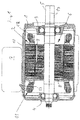
- the electric motor shown is a permanent magnet motor, with a motor housing 1, in which a stator 2 is arranged stationarily. In the end faces of the motor housing ball bearings 3, 4 are added, in which a shaft 5 of a rotor 6 is rotatably mounted.
- the motor housing 1 is essentially formed of three parts, namely a cylindrical, the stator 2 receiving housing part 15 with external and parallel to the axis of rotation cooling fins and two end caps 16 in which the ball bearings 3, 4, which support the rotor 6 , are recorded.
- a plane surface is provided on the upper side of the motor housing 1, where it is fastened.
- the rotor 6 has a rotor laminated core 8 in which magnets 9 are incorporated.
- the laminated core is divided in half, wherein the magnets 9 of the two halves have a certain angular offset.
- the laminated rotor core 8 with the magnets 9 is fixedly connected to the shaft 5 and rotatably mounted within the stator 2, which has a stator core 10 in the form of a Statorblechonges 10, are angeorndet in the motor windings 11.
- a shielding ring 13 is arranged in an axial continuation of the stator core 10 on both sides.
- the shields 13 in conjunction with the groove / winding training still described below represent a capacitive shielding and prevent the coupling of high-frequency currents, as typically generated in the frequency converter 7 as harmonics, which are induced by the stator windings 11 in the rotor 6 and there via the bearings 3, 4 drain into the motor housing 1 and short-circuited.
- appropriate shielding measures are taken in the described motor.
- shielding measures relate, on the one hand, to the arrangement of the motor windings 11 in the slots 14 of the stator core 10 and to the arrangement of the shielding rings 13.
- stator core 10 with the motor windings 11 arranged in the stator slots 14 is in Fig. 3 illustrated simplified with respect to the winding heads 12, which are simplified there illustrated as bead-like rings. It is understood that these are the usual winding heads, which connect the arranged in two grooves 14 of the stator core 10 winding parts together.
- each groove 14, which is formed in the stator core 10 extends over the entire length of the laminated stator core 10, which forms the stator core 10.
- the grooves 14 are arranged parallel to the motor axis 19 and are bounded by two substantially radially to the motor axis 19 extending lateral walls 20, the arcuate shape over the groove bottom 21st are merged.
- Radially inwardly, the lateral walls 20 pass into projections 22, which extend approximately tangentially and form a gap 23 which forms the part of the groove 14 which is open towards the rotor 6.
- the gap 23 is narrow, winding-free and extends over the entire length of the groove 14, through which the respective winding 11 is inserted into the groove 14.
- each groove 14 On the inside of each groove 14 is lined with a slot insulation 24 which completely surrounds the winding located in the groove 14 and electrically insulated from the metallic laminated core 10 and protects.
- the slot insulation 24 consists of two substantially U-shaped insulation pieces 25 and 26.
- the slot insulation part 25 extends over the groove bottom 21 to close to the projections 22 along the side walls 20.
- the other part 26 of the slot insulation 24 extends from the radially inner end the winding spaced apart from the projections 22 and the gap 23 formed therebetween over approximately one third of the length of the side walls 20.
- the Nutisolianssmaschine 26 and 25 overlap each other and interlock, as with reference to Fig. 5 is shown, in such a way that it is ensured even in telekopierter, ie exploded position that the groove 14 is completely lined with the slot insulation 24.
- the motor windings 11 are not groove filling arranged in the stator core 11, but, as described above, in the direction of the groove base 21 so shifted that a free space 27 is formed, which is winding-free.
- the motor windings 11 are arranged with a radial distance 28 to the column end or to the inside of the projections 22. This results in a free distance to the rotor 6, which is essential for the capacitive shielding in this area.
- Fig. 9 Based on Fig. 9 is shown, which shielding effect is given at which distance in millimeters. It is assumed at a distance of 1 mm from the 100% capacitive coupling, which 1 mm relate to the radial extent of the gap 23, ie the point where the distance 28 is zero, that is, where there is still no winding space available. Substituting the resulting capacitive coupling to 100%, it is apparent to what extent this decreases with increasing distance 28. If the distance 28, that is, the free space 27 in its radial extent to 1.5 mm extended (corresponds to 2.5 mm in Fig. 9 ), the capacitive coupling is only 40%, at 4 mm (corresponds to 5 mm in Fig. 9 ) is in the range of 5%.
- the motor windings 11 can be produced in a conventional manner, in which the winding wire is wound over gaps 23 in the respective slots until they have received an almost complete degree of filling. So then by a tool after heating the winding to a Verbacktemperatur in which the winding varnish is melted, this pushed together from the gap 23 from radially outward. The force is applied via a tool which does not act directly on the winding, but over the inner part 26 of the slot insulation 24, whereby the winding itself is protected from the tool. After the motor winding has been pushed together in the groove 14 to the desired level and so the desired clearance 27 has been generated with the distance 28, the winding is cooled so far that no Restoring forces occur more and the arrangement remains intrinsically stable. Already then, further manufacturing steps can be initiated before the winding is cooled back to ambient temperature.
- shielding rings 13 are provided. These shields 13 each consist of an outer ring 29 made of plastic, a plastic inner ring 30 and the actual shield in the form of a metallic ring 31.
- the inner ring 30 and outer ring 29 are klippbefestig each other by elastic tongues 32, wherein the metallic ring 31 between these rings 29 and 30 incorporated.
- the metallic ring 31 is formed of a stamped part in the form of a sheet metal strip 33, which is brought by bending in the annular shape.
- the sheet metal part 33 which in Fig. 8 is shown in unwound form, is 0.2 mm thick, its inherent stability is therefore obtained essentially by the inside and outside arranged plastic rings 29 and 30th
- the inner and outer rings 29, 30 have at their axial ends on projections 34 which are arranged circumferentially distributed in groups of three at the same distance over the ring.
- the arrangement is such that these triads of projections 34, when the outer and inner rings 29, 30 are clipped together, lie next to one another, ie radially in alignment with one another.
- the metallic ring 31 has projections 35, but for each group of three of the projections 34 only one projection 35. While the projections 34 on the plastic rings 29 and 30 have a rounded shape, as in particular Fig. 7 can be seen, the metallic projections 35 are also rounded, but more angular, in particular they project beyond the inside and outside adjacent projections 34 both laterally and axially.
- a metallic projection 35 a structure of a total of three projections, namely a middle Projection 34 of a Dreiervorsprung mich an inner ring 30, an abutting projection 35 of the metallic ring 31 and an outwardly adjacent projection 34 of a group of projections 34 of the outer ring 29.
- These structures consisting of abutting projections 34 and 35 and form a kind of plug contact the ensure that upon insertion of the projections 34, 35 in the ends of the grooves 14 of the stator core 10 on the one hand, a mechanical fixation on the other hand, however, an electrical contact takes place, which electrically connects the metallic ring 31 with the stator core 10.
- a total of 12 projections 35 and two times 36 projections 34 are provided on a shield ring 13, which engage in the corresponding front ends of the grooves 14.
- grooves 14 are provided, even if in Fig. 4 for reasons of clarity, a different number is shown.
- the shielding ring 13 can also be electrically connected to the stator core 10 in a different manner, however, at least four electrical connections distributed as uniformly as possible over the circumference must be created in order to ensure effective shielding from high-frequency currents.
- the shielding ring 13 need not necessarily extend over the entire axial length 36 of a winding head 12 for effective capacitive decoupling, but it is sufficient, an axial length 37 which is significantly lower.
- the relationship between these quantities is based on Fig. 10 shown. It is on the vertical axis analogous to Fig. 9 the capacitive coupling is shown and on the horizontal axis the ratio of the axial length 37 to the axial length 36 of the winding head. From this diagram it can be seen that already an axial length 37 of 40% of the axial length 36 of a Winding head 12 is sufficient to reduce the capacitive coupling to 40% of the original value. At 70% of the length, there is already a reduction to less than 20%. It should be noted that the capacitive coupling in the region of the winding heads on the order of magnitude significantly lower than in the area between the stator core 10 and rotor 6.
Landscapes
- Engineering & Computer Science (AREA)
- Power Engineering (AREA)
- Manufacturing & Machinery (AREA)
- Insulation, Fastening Of Motor, Generator Windings (AREA)
Priority Applications (1)
| Application Number | Priority Date | Filing Date | Title |
|---|---|---|---|
| EP15202549.0A EP3185405B1 (fr) | 2015-12-23 | 2015-12-23 | Moteur electrique |
Applications Claiming Priority (1)
| Application Number | Priority Date | Filing Date | Title |
|---|---|---|---|
| EP15202549.0A EP3185405B1 (fr) | 2015-12-23 | 2015-12-23 | Moteur electrique |
Publications (2)
| Publication Number | Publication Date |
|---|---|
| EP3185405A1 true EP3185405A1 (fr) | 2017-06-28 |
| EP3185405B1 EP3185405B1 (fr) | 2018-10-31 |
Family
ID=55024940
Family Applications (1)
| Application Number | Title | Priority Date | Filing Date |
|---|---|---|---|
| EP15202549.0A Active EP3185405B1 (fr) | 2015-12-23 | 2015-12-23 | Moteur electrique |
Country Status (1)
| Country | Link |
|---|---|
| EP (1) | EP3185405B1 (fr) |
Cited By (1)
| Publication number | Priority date | Publication date | Assignee | Title |
|---|---|---|---|---|
| DE102022003197A1 (de) | 2022-09-01 | 2022-10-27 | Mercedes-Benz Group AG | Elektrische Maschine, insbesondere für ein Kraftfahrzeug |
Citations (5)
| Publication number | Priority date | Publication date | Assignee | Title |
|---|---|---|---|---|
| US5821652A (en) * | 1996-08-28 | 1998-10-13 | Marathon Electric Manufacturing Corporation | Dynamoelectric machines with shaft voltage prevention method and structure |
| US5979087A (en) * | 1998-01-16 | 1999-11-09 | Reliance Electric Industrial Company | Electric motor having electrostatic shield arrangement |
| JP2003180044A (ja) * | 2001-12-07 | 2003-06-27 | Okuma Corp | ステータ及びその製造方法 |
| US20040056538A1 (en) * | 2001-01-09 | 2004-03-25 | Du Hung T. | Dynamoelectric machine having an encapsulated coil structure |
| WO2014002545A1 (fr) * | 2012-06-29 | 2014-01-03 | アイシン・エィ・ダブリュ株式会社 | Procédé permettant de fabriquer un conducteur linéaire et procédé permettant de fabriquer une machine électrique rotative |
-
2015
- 2015-12-23 EP EP15202549.0A patent/EP3185405B1/fr active Active
Patent Citations (5)
| Publication number | Priority date | Publication date | Assignee | Title |
|---|---|---|---|---|
| US5821652A (en) * | 1996-08-28 | 1998-10-13 | Marathon Electric Manufacturing Corporation | Dynamoelectric machines with shaft voltage prevention method and structure |
| US5979087A (en) * | 1998-01-16 | 1999-11-09 | Reliance Electric Industrial Company | Electric motor having electrostatic shield arrangement |
| US20040056538A1 (en) * | 2001-01-09 | 2004-03-25 | Du Hung T. | Dynamoelectric machine having an encapsulated coil structure |
| JP2003180044A (ja) * | 2001-12-07 | 2003-06-27 | Okuma Corp | ステータ及びその製造方法 |
| WO2014002545A1 (fr) * | 2012-06-29 | 2014-01-03 | アイシン・エィ・ダブリュ株式会社 | Procédé permettant de fabriquer un conducteur linéaire et procédé permettant de fabriquer une machine électrique rotative |
Non-Patent Citations (1)
| Title |
|---|
| MAGDUN O ET AL: "Prevention of harmful EDM currents in inverter-fed AC machines by use of electrostatic shields in the stator winding overhang", IECON 2010 - 36TH ANNUAL CONFERENCE ON IEEE INDUSTRIAL ELECTRONICS SOCIETY, IEEE, PISCATAWAY, NJ, USA, 7 November 2010 (2010-11-07), pages 962 - 967, XP031840554, ISBN: 978-1-4244-5225-5 * |
Cited By (1)
| Publication number | Priority date | Publication date | Assignee | Title |
|---|---|---|---|---|
| DE102022003197A1 (de) | 2022-09-01 | 2022-10-27 | Mercedes-Benz Group AG | Elektrische Maschine, insbesondere für ein Kraftfahrzeug |
Also Published As
| Publication number | Publication date |
|---|---|
| EP3185405B1 (fr) | 2018-10-31 |
Similar Documents
| Publication | Publication Date | Title |
|---|---|---|
| WO2020099048A1 (fr) | Dispositif de support conçu pour un rotor d'une machine synchrone à rotor interne à excitation séparée comprenant un anneau de support et un disque en étoile | |
| DE102015225088A1 (de) | Motor und Verfahren zum Herstellen desselben | |
| DE112014004639B4 (de) | Drehende elektrische Maschine und Herstellungsverfahren für diese | |
| WO1990009697A1 (fr) | Machine electrique excitee par des aimants permanents | |
| DE102011083128A1 (de) | Elektromotor | |
| DE112005000944T5 (de) | Bürstenloser Motor | |
| EP3127223B1 (fr) | Moteur électrique | |
| DE102013219186A1 (de) | Elektrische Maschine und Verbindungseinheit für elektrische Maschine. | |
| DE102012100332A1 (de) | Stator für eine rotierende elektrische Maschine und Verfahren zu seiner Herstellung | |
| EP2541740B1 (fr) | Stator | |
| EP3189582A2 (fr) | Rotor d'une machine électrique, machine électrique et procédé de fabrication du rotor d'une machine électrique | |
| WO2019002289A1 (fr) | Moteur électrique, en particulier pour véhicule | |
| WO2019110271A1 (fr) | Machine électrique, en particulier pour un véhicule | |
| WO2019110275A1 (fr) | Machine électrique, en particulier pour véhicule | |
| DE112017006320T5 (de) | Statorkern für eine elektrische rotationsmaschine und zugehöriges herstellungsverfahren | |
| WO2017012707A1 (fr) | Corps de noyau pour stators et/ou rotors de machines électriques et stator/rotor comportant un tel corps de noyau ainsi que machine électrique comportant un tel corps de noyau | |
| EP3185405B1 (fr) | Moteur electrique | |
| DE2913844C2 (de) | Nutisolierung für den Rotor einer elektrischen Maschine | |
| EP3012945B1 (fr) | Machine electrique dotee d'un carter | |
| EP0619638A2 (fr) | Machine électrique avec armature plat | |
| DE102017207663A1 (de) | Verfahren zur Herstellung einer Spulenanordnung | |
| EP3276797A1 (fr) | Rotor de machine rotative électrique | |
| DE102004008688B4 (de) | Linearmotor | |
| WO2018197133A1 (fr) | Stator segmenté pour moteur électrique du type à rotor interne | |
| DE102018222354A1 (de) | Statorgrundkörper für einen Elektromotor, Stator, Elektromotor und Verfahren zur Herstellung des Statorgrundkörpers |
Legal Events
| Date | Code | Title | Description |
|---|---|---|---|
| PUAI | Public reference made under article 153(3) epc to a published international application that has entered the european phase |
Free format text: ORIGINAL CODE: 0009012 |
|
| STAA | Information on the status of an ep patent application or granted ep patent |
Free format text: STATUS: THE APPLICATION HAS BEEN PUBLISHED |
|
| AK | Designated contracting states |
Kind code of ref document: A1 Designated state(s): AL AT BE BG CH CY CZ DE DK EE ES FI FR GB GR HR HU IE IS IT LI LT LU LV MC MK MT NL NO PL PT RO RS SE SI SK SM TR |
|
| AX | Request for extension of the european patent |
Extension state: BA ME |
|
| STAA | Information on the status of an ep patent application or granted ep patent |
Free format text: STATUS: REQUEST FOR EXAMINATION WAS MADE |
|
| 17P | Request for examination filed |
Effective date: 20171228 |
|
| RBV | Designated contracting states (corrected) |
Designated state(s): AL AT BE BG CH CY CZ DE DK EE ES FI FR GB GR HR HU IE IS IT LI LT LU LV MC MK MT NL NO PL PT RO RS SE SI SK SM TR |
|
| GRAP | Despatch of communication of intention to grant a patent |
Free format text: ORIGINAL CODE: EPIDOSNIGR1 |
|
| STAA | Information on the status of an ep patent application or granted ep patent |
Free format text: STATUS: GRANT OF PATENT IS INTENDED |
|
| RIC1 | Information provided on ipc code assigned before grant |
Ipc: H02K 3/42 20060101ALI20180302BHEP Ipc: H02K 15/00 20060101AFI20180302BHEP Ipc: H02K 3/38 20060101ALI20180302BHEP Ipc: H02K 3/34 20060101ALI20180302BHEP |
|
| INTG | Intention to grant announced |
Effective date: 20180319 |
|
| GRAS | Grant fee paid |
Free format text: ORIGINAL CODE: EPIDOSNIGR3 |
|
| GRAJ | Information related to disapproval of communication of intention to grant by the applicant or resumption of examination proceedings by the epo deleted |
Free format text: ORIGINAL CODE: EPIDOSDIGR1 |
|
| GRAL | Information related to payment of fee for publishing/printing deleted |
Free format text: ORIGINAL CODE: EPIDOSDIGR3 |
|
| STAA | Information on the status of an ep patent application or granted ep patent |
Free format text: STATUS: REQUEST FOR EXAMINATION WAS MADE |
|
| GRAR | Information related to intention to grant a patent recorded |
Free format text: ORIGINAL CODE: EPIDOSNIGR71 |
|
| STAA | Information on the status of an ep patent application or granted ep patent |
Free format text: STATUS: GRANT OF PATENT IS INTENDED |
|
| GRAA | (expected) grant |
Free format text: ORIGINAL CODE: 0009210 |
|
| STAA | Information on the status of an ep patent application or granted ep patent |
Free format text: STATUS: THE PATENT HAS BEEN GRANTED |
|
| INTC | Intention to grant announced (deleted) | ||
| INTG | Intention to grant announced |
Effective date: 20180920 |
|
| AK | Designated contracting states |
Kind code of ref document: B1 Designated state(s): AL AT BE BG CH CY CZ DE DK EE ES FI FR GB GR HR HU IE IS IT LI LT LU LV MC MK MT NL NO PL PT RO RS SE SI SK SM TR |
|
| REG | Reference to a national code |
Ref country code: CH Ref legal event code: EP Ref country code: GB Ref legal event code: FG4D Free format text: NOT ENGLISH |
|
| REG | Reference to a national code |
Ref country code: AT Ref legal event code: REF Ref document number: 1060577 Country of ref document: AT Kind code of ref document: T Effective date: 20181115 |
|
| REG | Reference to a national code |
Ref country code: DE Ref legal event code: R096 Ref document number: 502015006653 Country of ref document: DE |
|
| REG | Reference to a national code |
Ref country code: IE Ref legal event code: FG4D Free format text: LANGUAGE OF EP DOCUMENT: GERMAN |
|
| REG | Reference to a national code |
Ref country code: NL Ref legal event code: MP Effective date: 20181031 |
|
| REG | Reference to a national code |
Ref country code: LT Ref legal event code: MG4D |
|
| PG25 | Lapsed in a contracting state [announced via postgrant information from national office to epo] |
Ref country code: NO Free format text: LAPSE BECAUSE OF FAILURE TO SUBMIT A TRANSLATION OF THE DESCRIPTION OR TO PAY THE FEE WITHIN THE PRESCRIBED TIME-LIMIT Effective date: 20190131 Ref country code: BG Free format text: LAPSE BECAUSE OF FAILURE TO SUBMIT A TRANSLATION OF THE DESCRIPTION OR TO PAY THE FEE WITHIN THE PRESCRIBED TIME-LIMIT Effective date: 20190131 Ref country code: PL Free format text: LAPSE BECAUSE OF FAILURE TO SUBMIT A TRANSLATION OF THE DESCRIPTION OR TO PAY THE FEE WITHIN THE PRESCRIBED TIME-LIMIT Effective date: 20181031 Ref country code: LT Free format text: LAPSE BECAUSE OF FAILURE TO SUBMIT A TRANSLATION OF THE DESCRIPTION OR TO PAY THE FEE WITHIN THE PRESCRIBED TIME-LIMIT Effective date: 20181031 Ref country code: ES Free format text: LAPSE BECAUSE OF FAILURE TO SUBMIT A TRANSLATION OF THE DESCRIPTION OR TO PAY THE FEE WITHIN THE PRESCRIBED TIME-LIMIT Effective date: 20181031 Ref country code: LV Free format text: LAPSE BECAUSE OF FAILURE TO SUBMIT A TRANSLATION OF THE DESCRIPTION OR TO PAY THE FEE WITHIN THE PRESCRIBED TIME-LIMIT Effective date: 20181031 Ref country code: IS Free format text: LAPSE BECAUSE OF FAILURE TO SUBMIT A TRANSLATION OF THE DESCRIPTION OR TO PAY THE FEE WITHIN THE PRESCRIBED TIME-LIMIT Effective date: 20190228 Ref country code: HR Free format text: LAPSE BECAUSE OF FAILURE TO SUBMIT A TRANSLATION OF THE DESCRIPTION OR TO PAY THE FEE WITHIN THE PRESCRIBED TIME-LIMIT Effective date: 20181031 Ref country code: FI Free format text: LAPSE BECAUSE OF FAILURE TO SUBMIT A TRANSLATION OF THE DESCRIPTION OR TO PAY THE FEE WITHIN THE PRESCRIBED TIME-LIMIT Effective date: 20181031 |
|
| PG25 | Lapsed in a contracting state [announced via postgrant information from national office to epo] |
Ref country code: SE Free format text: LAPSE BECAUSE OF FAILURE TO SUBMIT A TRANSLATION OF THE DESCRIPTION OR TO PAY THE FEE WITHIN THE PRESCRIBED TIME-LIMIT Effective date: 20181031 Ref country code: GR Free format text: LAPSE BECAUSE OF FAILURE TO SUBMIT A TRANSLATION OF THE DESCRIPTION OR TO PAY THE FEE WITHIN THE PRESCRIBED TIME-LIMIT Effective date: 20190201 Ref country code: AL Free format text: LAPSE BECAUSE OF FAILURE TO SUBMIT A TRANSLATION OF THE DESCRIPTION OR TO PAY THE FEE WITHIN THE PRESCRIBED TIME-LIMIT Effective date: 20181031 Ref country code: RS Free format text: LAPSE BECAUSE OF FAILURE TO SUBMIT A TRANSLATION OF THE DESCRIPTION OR TO PAY THE FEE WITHIN THE PRESCRIBED TIME-LIMIT Effective date: 20181031 Ref country code: PT Free format text: LAPSE BECAUSE OF FAILURE TO SUBMIT A TRANSLATION OF THE DESCRIPTION OR TO PAY THE FEE WITHIN THE PRESCRIBED TIME-LIMIT Effective date: 20190301 Ref country code: NL Free format text: LAPSE BECAUSE OF FAILURE TO SUBMIT A TRANSLATION OF THE DESCRIPTION OR TO PAY THE FEE WITHIN THE PRESCRIBED TIME-LIMIT Effective date: 20181031 |
|
| PG25 | Lapsed in a contracting state [announced via postgrant information from national office to epo] |
Ref country code: DK Free format text: LAPSE BECAUSE OF FAILURE TO SUBMIT A TRANSLATION OF THE DESCRIPTION OR TO PAY THE FEE WITHIN THE PRESCRIBED TIME-LIMIT Effective date: 20181031 Ref country code: CZ Free format text: LAPSE BECAUSE OF FAILURE TO SUBMIT A TRANSLATION OF THE DESCRIPTION OR TO PAY THE FEE WITHIN THE PRESCRIBED TIME-LIMIT Effective date: 20181031 |
|
| REG | Reference to a national code |
Ref country code: CH Ref legal event code: PL |
|
| REG | Reference to a national code |
Ref country code: DE Ref legal event code: R097 Ref document number: 502015006653 Country of ref document: DE |
|
| PG25 | Lapsed in a contracting state [announced via postgrant information from national office to epo] |
Ref country code: EE Free format text: LAPSE BECAUSE OF FAILURE TO SUBMIT A TRANSLATION OF THE DESCRIPTION OR TO PAY THE FEE WITHIN THE PRESCRIBED TIME-LIMIT Effective date: 20181031 Ref country code: LU Free format text: LAPSE BECAUSE OF NON-PAYMENT OF DUE FEES Effective date: 20181223 Ref country code: RO Free format text: LAPSE BECAUSE OF FAILURE TO SUBMIT A TRANSLATION OF THE DESCRIPTION OR TO PAY THE FEE WITHIN THE PRESCRIBED TIME-LIMIT Effective date: 20181031 Ref country code: SK Free format text: LAPSE BECAUSE OF FAILURE TO SUBMIT A TRANSLATION OF THE DESCRIPTION OR TO PAY THE FEE WITHIN THE PRESCRIBED TIME-LIMIT Effective date: 20181031 Ref country code: MC Free format text: LAPSE BECAUSE OF FAILURE TO SUBMIT A TRANSLATION OF THE DESCRIPTION OR TO PAY THE FEE WITHIN THE PRESCRIBED TIME-LIMIT Effective date: 20181031 Ref country code: SM Free format text: LAPSE BECAUSE OF FAILURE TO SUBMIT A TRANSLATION OF THE DESCRIPTION OR TO PAY THE FEE WITHIN THE PRESCRIBED TIME-LIMIT Effective date: 20181031 |
|
| PLBE | No opposition filed within time limit |
Free format text: ORIGINAL CODE: 0009261 |
|
| STAA | Information on the status of an ep patent application or granted ep patent |
Free format text: STATUS: NO OPPOSITION FILED WITHIN TIME LIMIT |
|
| REG | Reference to a national code |
Ref country code: IE Ref legal event code: MM4A |
|
| REG | Reference to a national code |
Ref country code: BE Ref legal event code: MM Effective date: 20181231 |
|
| 26N | No opposition filed |
Effective date: 20190801 |
|
| PG25 | Lapsed in a contracting state [announced via postgrant information from national office to epo] |
Ref country code: IE Free format text: LAPSE BECAUSE OF NON-PAYMENT OF DUE FEES Effective date: 20181223 Ref country code: SI Free format text: LAPSE BECAUSE OF FAILURE TO SUBMIT A TRANSLATION OF THE DESCRIPTION OR TO PAY THE FEE WITHIN THE PRESCRIBED TIME-LIMIT Effective date: 20181031 |
|
| PG25 | Lapsed in a contracting state [announced via postgrant information from national office to epo] |
Ref country code: BE Free format text: LAPSE BECAUSE OF NON-PAYMENT OF DUE FEES Effective date: 20181231 |
|
| PG25 | Lapsed in a contracting state [announced via postgrant information from national office to epo] |
Ref country code: CH Free format text: LAPSE BECAUSE OF NON-PAYMENT OF DUE FEES Effective date: 20181231 Ref country code: LI Free format text: LAPSE BECAUSE OF NON-PAYMENT OF DUE FEES Effective date: 20181231 |
|
| PG25 | Lapsed in a contracting state [announced via postgrant information from national office to epo] |
Ref country code: MT Free format text: LAPSE BECAUSE OF FAILURE TO SUBMIT A TRANSLATION OF THE DESCRIPTION OR TO PAY THE FEE WITHIN THE PRESCRIBED TIME-LIMIT Effective date: 20181031 |
|
| PG25 | Lapsed in a contracting state [announced via postgrant information from national office to epo] |
Ref country code: TR Free format text: LAPSE BECAUSE OF FAILURE TO SUBMIT A TRANSLATION OF THE DESCRIPTION OR TO PAY THE FEE WITHIN THE PRESCRIBED TIME-LIMIT Effective date: 20181031 |
|
| PG25 | Lapsed in a contracting state [announced via postgrant information from national office to epo] |
Ref country code: MK Free format text: LAPSE BECAUSE OF NON-PAYMENT OF DUE FEES Effective date: 20181031 Ref country code: CY Free format text: LAPSE BECAUSE OF FAILURE TO SUBMIT A TRANSLATION OF THE DESCRIPTION OR TO PAY THE FEE WITHIN THE PRESCRIBED TIME-LIMIT Effective date: 20181031 Ref country code: HU Free format text: LAPSE BECAUSE OF FAILURE TO SUBMIT A TRANSLATION OF THE DESCRIPTION OR TO PAY THE FEE WITHIN THE PRESCRIBED TIME-LIMIT; INVALID AB INITIO Effective date: 20151223 |
|
| REG | Reference to a national code |
Ref country code: AT Ref legal event code: MM01 Ref document number: 1060577 Country of ref document: AT Kind code of ref document: T Effective date: 20201223 |
|
| PG25 | Lapsed in a contracting state [announced via postgrant information from national office to epo] |
Ref country code: AT Free format text: LAPSE BECAUSE OF NON-PAYMENT OF DUE FEES Effective date: 20201223 |
|
| REG | Reference to a national code |
Ref country code: DE Ref legal event code: R082 Ref document number: 502015006653 Country of ref document: DE |
|
| PGFP | Annual fee paid to national office [announced via postgrant information from national office to epo] |
Ref country code: GB Payment date: 20231220 Year of fee payment: 9 |
|
| PGFP | Annual fee paid to national office [announced via postgrant information from national office to epo] |
Ref country code: IT Payment date: 20231228 Year of fee payment: 9 Ref country code: FR Payment date: 20231221 Year of fee payment: 9 Ref country code: DE Payment date: 20231214 Year of fee payment: 9 |