EP3185405A1 - Electric motor - Google Patents
Electric motor Download PDFInfo
- Publication number
- EP3185405A1 EP3185405A1 EP15202549.0A EP15202549A EP3185405A1 EP 3185405 A1 EP3185405 A1 EP 3185405A1 EP 15202549 A EP15202549 A EP 15202549A EP 3185405 A1 EP3185405 A1 EP 3185405A1
- Authority
- EP
- European Patent Office
- Prior art keywords
- winding
- stator
- electric motor
- stator core
- motor according
- Prior art date
- Legal status (The legal status is an assumption and is not a legal conclusion. Google has not performed a legal analysis and makes no representation as to the accuracy of the status listed.)
- Granted
Links
- 238000004804 winding Methods 0.000 claims abstract description 121
- 230000008878 coupling Effects 0.000 claims abstract description 19
- 238000010168 coupling process Methods 0.000 claims abstract description 19
- 238000005859 coupling reaction Methods 0.000 claims abstract description 19
- 239000002184 metal Substances 0.000 claims description 21
- 238000009413 insulation Methods 0.000 claims description 20
- 238000000034 method Methods 0.000 claims description 13
- 238000004519 manufacturing process Methods 0.000 claims description 10
- 238000001816 cooling Methods 0.000 claims description 8
- 238000010438 heat treatment Methods 0.000 claims description 6
- 238000003780 insertion Methods 0.000 abstract description 3
- 230000037431 insertion Effects 0.000 abstract description 3
- 230000004323 axial length Effects 0.000 description 8
- 238000005516 engineering process Methods 0.000 description 4
- 238000011161 development Methods 0.000 description 3
- 230000018109 developmental process Effects 0.000 description 3
- 230000000694 effects Effects 0.000 description 3
- 239000002966 varnish Substances 0.000 description 3
- 238000006073 displacement reaction Methods 0.000 description 2
- 238000010292 electrical insulation Methods 0.000 description 2
- 230000001965 increasing effect Effects 0.000 description 2
- 239000000463 material Substances 0.000 description 2
- 230000003071 parasitic effect Effects 0.000 description 2
- 238000003825 pressing Methods 0.000 description 2
- 238000005096 rolling process Methods 0.000 description 2
- 210000002105 tongue Anatomy 0.000 description 2
- 238000012549 training Methods 0.000 description 2
- 238000005452 bending Methods 0.000 description 1
- 230000006835 compression Effects 0.000 description 1
- 238000007906 compression Methods 0.000 description 1
- 238000002788 crimping Methods 0.000 description 1
- 230000007423 decrease Effects 0.000 description 1
- 230000001419 dependent effect Effects 0.000 description 1
- 238000013461 design Methods 0.000 description 1
- 238000010586 diagram Methods 0.000 description 1
- 239000000945 filler Substances 0.000 description 1
- 238000010348 incorporation Methods 0.000 description 1
- 230000001939 inductive effect Effects 0.000 description 1
- 238000003475 lamination Methods 0.000 description 1
- 239000003973 paint Substances 0.000 description 1
- 230000002028 premature Effects 0.000 description 1
- 238000011144 upstream manufacturing Methods 0.000 description 1
Images


Classifications
-
- H—ELECTRICITY
- H02—GENERATION; CONVERSION OR DISTRIBUTION OF ELECTRIC POWER
- H02K—DYNAMO-ELECTRIC MACHINES
- H02K15/00—Methods or apparatus specially adapted for manufacturing, assembling, maintaining or repairing of dynamo-electric machines
- H02K15/0025—Shaping or compacting conductors or winding heads after the installation of the winding in the core or machine ; Applying fastening means on winding heads
- H02K15/0031—Shaping or compacting conductors in slots or around salient poles
-
- H—ELECTRICITY
- H02—GENERATION; CONVERSION OR DISTRIBUTION OF ELECTRIC POWER
- H02K—DYNAMO-ELECTRIC MACHINES
- H02K3/00—Details of windings
- H02K3/32—Windings characterised by the shape, form or construction of the insulation
- H02K3/34—Windings characterised by the shape, form or construction of the insulation between conductors or between conductor and core, e.g. slot insulation
- H02K3/345—Windings characterised by the shape, form or construction of the insulation between conductors or between conductor and core, e.g. slot insulation between conductor and core, e.g. slot insulation
-
- H—ELECTRICITY
- H02—GENERATION; CONVERSION OR DISTRIBUTION OF ELECTRIC POWER
- H02K—DYNAMO-ELECTRIC MACHINES
- H02K3/00—Details of windings
- H02K3/32—Windings characterised by the shape, form or construction of the insulation
- H02K3/38—Windings characterised by the shape, form or construction of the insulation around winding heads, equalising connectors, or connections thereto
-
- H—ELECTRICITY
- H02—GENERATION; CONVERSION OR DISTRIBUTION OF ELECTRIC POWER
- H02K—DYNAMO-ELECTRIC MACHINES
- H02K3/00—Details of windings
- H02K3/42—Means for preventing or reducing eddy-current losses in the winding heads, e.g. by shielding
-
- H—ELECTRICITY
- H02—GENERATION; CONVERSION OR DISTRIBUTION OF ELECTRIC POWER
- H02K—DYNAMO-ELECTRIC MACHINES
- H02K2213/00—Specific aspects, not otherwise provided for and not covered by codes H02K2201/00 - H02K2211/00
- H02K2213/03—Machines characterised by numerical values, ranges, mathematical expressions or similar information
Abstract
Der Elektromotor weist einen Stator (2) und einen darin rotierbar gelagerten Rotor (6) auf. Der Stator (2) weist einen Statorkern (10) in Statornuten angeordneten Motorwicklungen (11) auf, deren Wicklungsköpfe (12) sich endseitig und außerhalb der Nuten erstrecken, wobei zwischen den Wicklungsköpfen (12) und dem Rotor (6) Wicklungskopfabschirmungen (13) angeordnet sind. Die Statornuten sind jeweils zum Rotor hin offen und weisen neben dem wicklungsfreien Spalt, der zum Einliegen des Drahtes erforderlich ist, einen wicklungsfreien Raum auf, und zwar im Bereich zwischen in den Nuten befindlichen Wicklungsteilen und dem jeweiligen Spalt. Dieser wicklungsfreie Raum in Verbindung mit den Abschirmungen (13) dient zur Verringerung der kapazitiven Kopplung zwischen Rotor und Stator.The electric motor has a stator (2) and a rotatably mounted rotor (6). The stator (2) has a stator core (10) in stator slots arranged motor windings (11), the winding heads (12) extending end and outside of the grooves, wherein between the winding heads (12) and the rotor (6) winding head shields (13) are arranged. The stator slots are each open to the rotor and, in addition to the winding-free gap, which is required for the insertion of the wire, a winding-free space, in the region between located in the grooves winding parts and the respective gap. This winding-free space in conjunction with the shields (13) serves to reduce the capacitive coupling between the rotor and stator.
Description
Die Erfindung betrifft einen Elektromotor mit einem Stator und einem darin rotierbar gelagerten Rotor, der zum Betrieb mit einem Frequenzumformer geeignet ist.The invention relates to an electric motor with a stator and a rotor rotatably mounted therein, which is suitable for operation with a frequency converter.
Es zählt zum Stand der Technik, Elektromotoren, beispielsweise Asynchronmotoren oder Permanentmagnetmotoren mittels eines elektronischen Drehzahlstellers anzusteuern. So werden Frequenzumrichter eingesetzt, welche den Wechsel- oder Drehstrom zunächst in einen Gleichstrom umwandeln, um ihn dann mittels elektronischer Schalter in einen Strom gewünschter Amplitude und Frequenz zu wandeln. Die durch den Frequenzumrichter erzeugten Wechselströme entsprechen zwar hinsichtlich Amplitudenverlauf und Frequenz den gewünschten Vorgaben, weisen jedoch keine reine Sinusform auf, sondern sind aufgrund der schnellen Schaltvorgänge, durch die das jeweilige Signal erzeugt wird, mit hochfrequenten Oberwellen behaftet. Diese hochfrequenten Signalanteile gelangen durch kapazitive Kopplung zunächst vom Stator in den Rotor von dort in das Motorgehäuse. Insbesondere bei Elektromotoren, die einen kugelgelagerten Rotor aufweisen, ergibt sich das Problem, dass diese Ströme im Bereich der Lager vom Rotor auf den Stator übertreten, was dazu führt, dass die Oberfläche der Wälzkörper, insbesondere der Kugeln punktuell verändert wird, wodurch der Lagerverschleiß erhöht und letztlich die Standzeit des Motors verringert wird.It belongs to the state of the art to drive electric motors, for example asynchronous motors or permanent magnet motors by means of an electronic speed controller. Thus, frequency converters are used, which first convert the alternating or three-phase current into a direct current, in order then to convert it by means of electronic switches into a current of the desired amplitude and frequency. Although the alternating currents generated by the frequency converter correspond to the desired specifications in terms of amplitude and frequency, they are not pure sine-wave, but are subject to high-frequency harmonics due to the fast switching processes by which the respective signal is generated. These high-frequency signal components first pass through the capacitive coupling from the stator into the rotor from there into the motor housing. In particular, in electric motors having a ball-bearing rotor, there is the problem that these currents in the region of the bearings from the rotor to the stator, resulting in that the surface of the rolling elements, in particular the balls is selectively changed, whereby the bearing wear increases and ultimately the life of the engine is reduced.
Es zählt zum Stand der Technik, zwischen Wicklungskopf und Rotor Abschirmbleche vorzusehen, um die parasitären Ströme zu verringern, was jedoch in der Praxis nicht ausreicht, um vorzeitige Lagerschäden sicher zu vermeiden.It is state of the art to provide shielding plates between the winding head and the rotor in order to reduce the parasitic currents. However, this is not enough in practice to safely prevent premature bearing damage.
Vor diesem Hintergrund liegt der Erfindung die Aufgabe zugrunde, einen Elektromotor so auszubilden, dass auch bei Ansteuerung durch einen Frequenzumrichter oder anderen elektronischen Drehzahlsteller keine erhöhte Lagerbelastung durch solche hochfrequenten Ströme auftritt.Against this background, the invention has the object, an electric motor in such a way that even when controlled by a frequency converter or other electronic speed controller no increased bearing load occurs by such high-frequency currents.
Diese Aufgabe wird gemäß der Erfindung durch einen Elektromotor mit den in Anspruch 1 angegebenen Merkmalen gelöst. Vorteilhafte Ausgestaltungen der Erfindung sind in den Unteransprüchen, der nachfolgenden Beschreibung und der Zeichnung angegeben. Dabei können die in den Unteransprüchen und der Beschreibung angegebenen Merkmale jeweils für sich aber auch in geeigneter Kombination die erfindungsgemäße Lösung gemäß Anspruch 1 weiter ausgestalten.This object is achieved according to the invention by an electric motor having the features specified in
Der erfindungsgemäße Elektromotor weist einen Stator und einen darin rotierbar gelagerten Rotor auf. Der Stator weist einen Statorkern mit Statornuten auf, in denen Statorwicklungen aufgenommen sind, welche Wicklungsköpfe aufweisen, die sich endseitig und außerhalb der Nuten erstrecken. Zwischen den Wicklungsköpfen und dem Rotor sind Wicklungskopfabschirmungen angeordnet, wobei die Statornuten jeweils einen zum Rotor offen und wicklungsfreien Spalt aufweisen. Zwischen den in den Nuten befindlichen Wicklungsteilen und dem Spalt ist jeweils ein wicklungsfreier Raum in der Statornut gebildet ist. Dieser wicklungsfreie Raum ist vorzugsweise mit Luft gefüllt. Er besteht aus einem mit Luft oder einem anderen Füllstoff gebildeten Raum sowie dem Raum für die Nutisolierung, in dem ebenfalls keine Wicklung vorhanden ist.The electric motor according to the invention has a stator and a rotatably mounted rotor therein. The stator has a stator core with stator slots, in which stator windings are accommodated, which have winding heads which extend at the end and outside of the slots. Winding head shields are arranged between the winding heads and the rotor, wherein the stator slots each have a gap which is open to the rotor and has no winding. Between the located in the grooves winding parts and the gap a winding-free space in the stator is formed in each case. This winding-free space is preferably filled with air. It consists of a space formed with air or other filler and the space for the slot insulation, in which also no winding is present.
Die vorliegende Erfindung ist insbesondere für einen frequenzumrichtergesteuerten Elektromotor vorgesehen, es versteht sich, dass der erfindungsgemäße Elektromotor auch in Verbindung mit jeder anderen geeigneten Ansteuerung einsetzbar ist.The present invention is particularly intended for a frequency converter controlled electric motor, it is understood that the electric motor according to the invention can also be used in conjunction with any other suitable control.
Grundgedanke der vorliegenden Erfindung ist es, die in den Nuten befindlichen Wicklungsteile möglichst tief in die Nut, das heißt radial nach außen, einzugliedern, um den Abstand zwischen Wicklung und Rotor so weit zu vergrößern, dass nach Möglichkeit keine, zumindest aber eine wesentlich verminderte, insbesondere kapazitive Kopplung Erfindung für hochfrequente Ströme zwischen Rotor und Stator erfolgt. So ist gemäß der Erfindung ein wicklungsfreier Raum in jeder Statornut vorgesehen, der sich vom Spalt, das heißt vom radial äußeren Ende des Spaltes - dies ist das nutseitige Ende des Spaltes - bis zu dem in der Nut liegenden Teil der Wicklung erstreckt, der dafür sorgt, dass die kapazitive Kopplung in diesem Bereich zwischen Stator und Rotor ganz erheblich gemindert wird, typischerweise auf mindestens 40%, vorzugsweise auf 5 - 30% der maximalen kapazitiven Kopplung.The basic idea of the present invention is to integrate the winding parts located in the slots as deep as possible into the groove, ie radially outwards, in order to increase the distance between the winding and the rotor so far that, if possible, none, or at least a substantially reduced, In particular, capacitive coupling invention for high-frequency currents between the rotor and stator takes place. Thus, according to the invention, a winding-free space is provided in each stator slot extending from the gap, that is from the radially outer end of the gap - this is the groove-side end of the gap - to the in-slot portion of the winding which provides for it in that the capacitive coupling in this region between stator and rotor is considerably reduced, typically to at least 40%, preferably to 5 to 30%, of the maximum capacitive coupling.
Die Bezeichnungen Rotor und Stator im Sinne der vorliegenden Erfindung dienen in erster Linie zur Unterscheidung der Bauteile, sind jedoch nicht auf deren übliche Funktionalität dahingehend, dass der Rotor innerhalb des Stators drehbar gelagert ist beschränkt, sondern sie können im Sinne der Erfindung auch kinematisch umgekehrt sein, wenn es sich beispielsweise um einen Außenläufer handeltThe terms rotor and stator in the sense of the present invention serve primarily to distinguish the components, but are not limited to their usual functionality in that the rotor is rotatably mounted within the stator, but they can also be kinematically reversed in the sense of the invention if it is, for example, an external rotor
Die erfindungsgemäße Ausgestaltung kann grundsätzlich mit Elektromotoren unterschiedlicher Bauart eingesetzt werden, beispielsweise Asynchronmotoren oder Permanentmagnetmotoren.The embodiment according to the invention can in principle be used with electric motors of different types, for example asynchronous motors or permanent magnet motors.
Auch wenn durch diese erfindungsgemäße Maßnahme des wicklungsfreien Raumes die für den Lagerverschleiß wesentliche kapazitive Kopplung deutlich vermindert werden kann, so ist eine weitere Kopplung im Bereich zwischen den Wicklungsköpfen und Rotor gegeben. Diese wird gemäß der Erfindung durch Wicklungskopfabschirmungen deutlich reduziert, deren Ausbildung weiter unten noch im Einzelnen beschrieben istEven if by this inventive measure of the winding-free space essential for the bearing wear capacitive Coupling can be significantly reduced, so there is a further coupling in the area between the winding heads and rotor. This is significantly reduced according to the invention by Wicklungskopfabschirmungen whose training is described below in detail
Als besonders vorteilhaft hat es sich erwiesen, den radialen Abstand zwischen den in den Nuten befindlichen Wicklungsteilen und dem wicklungsfreien Spalt, also den Wicklungsteilen und den den Spalt begrenzenden seitlichen Vorsprüngen, welche die Nut zum Rotor hin begrenzen, mit mindestens zwei Millimetern zu dimensionieren. Dieser radiale Abstand, also die radiale Erstreckung des wicklungsfreien Raums in der Statornut sollte jedoch vorzugsweise zwischen drei und sieben Millimetern betragen, da dann eine nahezu vollständige kapazitive Abschirmung in diesem Bereich erreicht ist.It has proved to be particularly advantageous to dimension the radial distance between the winding parts located in the grooves and the winding-free gap, ie the winding parts and the lateral projections delimiting the gap, which delimit the groove towards the rotor, with at least two millimeters. However, this radial distance, that is to say the radial extension of the winding-free space in the stator slot, should preferably be between three and seven millimeters, since an almost complete capacitive shielding in this area is then achieved.
Um sicherzustellen, dass die Wicklung keinen Kurzschluss über den Statorkern erfährt - der Statorkern ist vorzugsweise als Statorblechpaket ausgestaltet - ist vorteilhaft eine Nutisolierung vorgesehen, welche den in der Nut befindlichen Wicklungsteil vorzugsweise vollständig umschließt. Gemäß einer vorteilhaften Ausgestaltung der Erfindung ist die Nutisolierung am Wicklungsteil anliegend angeordnet, das heißt so angeordnet, dass sie zwischen dem wicklungsfreien Raum und der Wicklung liegt. Der wicklungsfreie Raum wird somit radial nach innen durch den Spalt bzw. die beiden diesen Spalt begrenzender Vorsprünge des Statorkerns gebildet, seitlich durch die seitlichen Nutwandungen des Statorkerns und radial nach außen durch die Nutisolierung, die genau genommen auch noch Teil des wicklungsfreien Raumes ist. Eine solche Anordnung ist insbesondere fertigungstechnisch besonders vorteilhaft, da, wie weiter unten noch angegeben ist, das radiale Einpressen des in der Nut befindlichen Wicklungsteils dann unter Schutz der Nutisolierung erfolgen kann.In order to ensure that the winding does not undergo a short circuit via the stator core-the stator core is preferably designed as a stator lamination stack-a slot insulation is advantageously provided which preferably completely surrounds the winding part located in the groove. According to an advantageous embodiment of the invention, the slot insulation is arranged adjacent to the winding part, that is arranged so that it lies between the winding-free space and the winding. The winding-free space is thus formed radially inwardly through the gap or the two projections delimiting this gap of the stator core, laterally through the side groove walls of the stator core and radially outward through the slot insulation, which, strictly speaking, is also part of the winding-free space. Such an arrangement is especially particularly advantageous in terms of manufacturing technology since, as will be explained below, the radial pressing in of the winding part located in the groove can then take place while protecting the slot insulation.
Die Wicklungskopfabschirmungen werden gemäß einer vorteilhaften Weiterbildung der Erfindung durch mindestens einen Abschirmring zwischen den Wicklungsköpfen und dem Rotor gebildet, der axial an den Statorkern anschließt und der elektrisch leitend mit dem Statorkern verbunden ist. Ein solcher Abschirmring ist vorteilhaft zu beiden Seiten des Statorkerns vorgesehen.The winding head shields are formed according to an advantageous development of the invention by at least one shield between the winding heads and the rotor, which connects axially to the stator core and is electrically connected to the stator core. Such a shielding ring is advantageously provided on both sides of the stator core.
Dabei hat sich erstaunlicherweise gezeigt, dass für eine gute kapazitive Abschirmung die axiale Erstreckung des Abschirmrings durchaus kleiner als die axiale Erstreckung der davon abgeschirmten Wicklungsköpfe sein kann. Eine gute Abschirmung wird bereits erreicht, wenn die axiale Erstreckung des Abschirmrings, und zwar insbesondere die des für die Abschirmung wirksamen Metallteils des Rings, mindestens 40% der axialen Erstreckung der dadurch abgeschirmten Wicklungsköpfe beträgt. Da der größte Teil der parasitären Ströme bereits durch die Maßnahme des wicklungsfreien Raumes in jeder Statornut unterdrückt wird, kann es in der Praxis genügen, den von den Wicklungsköpfen ausgehenden Effekt lediglich deutlich zu vermindern. So kann bereits eine mehr als 50% reduzierte kapazitive Ankopplung im Bereich der Wicklungsköpfe erzielt werden, wenn die axiale Erstreckung des Abschirmrings etwa 40% der axialen Erstreckung der damit abgeschirmten Wicklungsköpfe beträgt. Die Kombination der kapazitiven Abschirmung durch ein Abschirmblech im Kopfbereich der Wicklungen und durch ein Tieferlegen der Wicklungen in den Statornuten ist besonders vorteilhaft, da sie soweit sie die Maßnahmen im Bereich der Statornuten angeht, praktisch keine Einflüsse auf die induktiven Vorgänge im Motor hat, anders als beim Einsatz von Abschirmblechen im Nutbereich. Darüber hinaus ist der Einsatz von Abschirmblechen im Nutbereich auch fertigungstechnisch problematisch, da die Bleche zum einen in die Nut eingebracht und zum anderen in der eingebrachten Stellung fixiert werden müssen. Bei dem erfindungsgemäßen Tieferlegen der Wicklung in der Nut hingegen ist lediglich das Einschieben der Wicklung in den Nutgrund, das heißt das Verpressen der Wicklung als weiterer Verfahrensschritt vorzusehen, wohingegen die übrigen Verfahrensschritte im Wesentlichen erhalten bleiben. Das ohnehin erforderliche Verbacken der Wicklung wird hier gleichzeitig zur Fixierung der Wicklung innerhalb der Nut genutzt, was von Vorteil ist.It has surprisingly been found that for a good capacitive shielding the axial extent of the shielding ring can be quite smaller than the axial extent of the shielded from this end winding heads. Good shielding is already achieved if the axial extent of the shielding ring, and in particular that of the shielding metal part of the ring, is at least 40% of the axial extent of the winding heads shielded thereby. Since the largest part of the parasitic currents is already suppressed by the measure of the winding-free space in each stator slot, in practice it may be sufficient only to significantly reduce the effect emanating from the winding heads. Thus, a more than 50% reduced capacitive coupling in the region of the winding heads can already be achieved if the axial extent of the shielding ring is about 40% of the axial extent of the winding heads shielded therefrom. The combination of the capacitive shielding through a shielding plate in the head region of the windings and by lowering the windings in the stator slots is particularly advantageous since, as far as the measures in the area of the stator slots are concerned, it has practically no influence on the inductive processes in the motor when using shielding plates in the groove area. In addition, the use of shielding in the groove area and manufacturing technology is problematic because the sheets must firstly be introduced into the groove and fixed to the other in the inserted position. By contrast, in the lowering of the winding in the groove according to the invention, only the insertion of the winding into the groove base is necessary, that is, to provide the crimping of the winding as a further method step, whereas the remaining method steps essentially remain intact. The already required baking of the winding is used here at the same time for fixing the winding within the groove, which is advantageous.
Vorteilhaft ist der Abschirmring nicht nur elektrisch mit dem Statorkern verbunden, sondern auch an diesem befestigt. Dabei besteht der Abschirmring aus einer metallischen Abschirmung, die vorteilhaft mindestens teilweise kunststoffummantelt ist. Diese Kunststoffummantelung hat zum einen den Effekt eine elektrische Isolierung zu bilden und zum anderen kann diese eine Tragfunktion haben.Advantageously, the shield is not only electrically connected to the stator core, but also attached to this. In this case, the shield consists of a metallic shield, which is advantageously at least partially plastic coated. This plastic casing has the effect on the one hand to form an electrical insulation and on the other hand, this can have a supporting function.
Da die Herstellung eines umschlossenen metallischen Rings aus Rundmaterial, z.B. einem Rohr vergleichsweise aufwendig ist, sieht eine erfindungsgemäße Weiterbildung vor, den metallischen Teil der Abschirmung aus einem metallischen Blechstreifen zu bilden, der in mindestens einen umgebenden Kunststoffring umlaufend eingegliedert ist. Ein solcher außen umlaufender Kunststoffring hält den Blechstreifen in seiner Ringform und bildet zugleich eine Isolierung zu den Wicklungsköpfen hin.Since the manufacture of an enclosed metallic ring of round material, e.g. a tube is relatively expensive, provides a further development according to the invention, to form the metallic part of the shield of a metallic sheet metal strip, which is incorporated circumferentially in at least one surrounding plastic ring. Such an outer circumferential plastic ring holds the metal strip in its ring shape and at the same time forms an insulation to the winding heads.
Besonders vorteilhaft allerdings ist eine erfindungsgemäße Ausgestaltung, bei welcher der metallische Blechstreifen ebenfalls zu einem Ring geformt ist, jedoch an der Innen- und an der Außenseite jeweils mit einem Kunststoffring versehen ist, wobei die beiden Kunststoffringe unter Eingliederung des zu einem Ring geformten Blechstreifens oder metallischen Rings miteinander klippbefestigt sind. Eine solche Ausgestaltung ist insbesondere unter Verwendung eines vergleichsweise dünnen Metallblechstreifens sinnvoll. Auf diese Weise kann der die metallische Abschirmung bildende Teil durch ein kostengünstiges und dünnes Stanzteil aus Metall gebildet sein, wohingegen die Tragfunktion im Wesentlichen durch die umgebenden Kunststoffringe gebildet ist, welche zudem die elektrische Isolierung bilden. Durch die Klippbefestigung kann eine sehr einfache und automatisierte Herstellung erfolgen, wobei nach Eingliederung des Metallteils in die Kunststoffringe quasi ein Bauteil gebildet ist, welches auch wie ein Bauteil handhabbar ist.Particularly advantageous, however, is an embodiment of the invention, in which the metallic sheet metal strip is also formed into a ring, but is provided on the inside and on the outside each with a plastic ring, the two plastic rings under inclusion of the formed into a ring metal strip or metallic Rings are clamped together. Such a configuration is particularly useful using a comparatively thin sheet metal strip. In this way, the metallic shield forming part may be formed by a low-cost and thin stamped metal part, whereas the supporting function is essentially formed by the surrounding plastic rings, which also form the electrical insulation. By the clip attachment can be made a very simple and automated production, wherein after incorporation of the metal part in the plastic rings quasi a component is formed, which is also handled as a component.
Zur Befestigung des Abschirmrings weist vorteilhaft mindestens der eine, vorzugsweise jedoch beide Kunststoffringe axiale Vorsprünge auf, die zum Statorkern gerichtet sind und zur mechanischen Befestigung und Festlegung des Abschirmrings zum Stator dienen. Diese Vorsprünge sind entweder in gesonderten Ausnehmungen des Statorkerns oder aber bevorzugt in den axialen Enden der Statornuten eingesetzt. Dabei weist vorteilhaft auch der die eigentliche Abschirmung bildende metallische Ring, der durch einen Blechstreifen gebildet sein kann, solche zum Statorkern gerichteten Vorsprünge auf, die in Ausnehmungen oder vorzugsweise ebenfalls in den Nuten des Statorkerns eingreifen und zur elektrischen Kontaktierung mit dem Statorkern aber auch zur mechanischen Befestigung dienen, wenn diese Vorsprünge in die Nutenden eingepresst sind.For attachment of the shielding ring advantageously has at least one, but preferably both plastic rings on axial projections, which are directed to the stator core and are used for mechanical attachment and fixing the shielding ring to the stator. These projections are inserted either in separate recesses of the stator core or preferably in the axial ends of the stator slots. Advantageously, the metal ring forming the actual shielding, which may be formed by a sheet metal strip, also has projections directed towards the stator core, which engage in recesses or preferably also in the slots of the stator core and also for mechanical contacting with the stator core Attachment serve when these projections are pressed into the Nutenden.
Dabei sind gemäß einer vorteilhaften Weiterbildung der Erfindung die Vorsprünge an dem Ring, insbesondere an den durch den Blechstreifen gebildeten Ring und den Kunststoffringen so angeordnet, dass ein metallischer Vorsprung von zwei Vorsprüngen der Kunststoffringe radial innen bzw. radial außen umgeben ist. Hierdurch wird erreicht, dass selbst bei dünnen Materialstärken der metallische Vorsprung eine ausreichende Stabilität erhält. Um eine elektrische Verbindung zwischen dem metallischen Vorsprung und dem Statorkern einerseits und eine ausreichende Eigenstabilität andererseits zu gewährleisten, ist ein metallischer Vorsprung zwar von stützenden Vorsprüngen aus Kunststoff an der Innen- und Außenseite umgeben, doch überragt dieser metallische Vorsprung zumindest seitlich, das heißt in Umfangsrichtung, vorzugsweise jedoch auch axial die Vorsprünge aus Kunststoff, so dass beim Einführen dieses aus drei aneinander anliegenden Vorsprüngen bestehende Gebildes in das Nutende eine Kontaktierung zwischen den überragenden Bereichen des metallischen Vorsprungs und dem Statorkern erfolgt.In this case, according to an advantageous development of the invention, the projections on the ring, in particular on the ring formed by the metal strip and the plastic rings are arranged so that a metallic projection of two projections of the plastic rings radially inside and radially outside is surrounded. This ensures that even with thin material thicknesses of the metallic projection receives sufficient stability. In order to ensure an electrical connection between the metallic projection and the stator core on the one hand and a sufficient intrinsic stability on the other hand, a metallic projection is indeed surrounded by supporting projections made of plastic on the inside and outside, but this metallic projection projects beyond at least laterally, that is in the circumferential direction , preferably but also axially the projections made of plastic, so that when inserting this from three abutting projections existing structure in the Nutende a contacting between the projecting portions of the metallic projection and the stator core takes place.
Grundsätzlich kann der wicklungsfreie Raum, wie er gemäß der Erfindung zur kapazitiven Entkopplung im Bereich der Nuten vorgesehen ist, durch entsprechende Wicklungsverfahren geschaffen werden. Um jedoch einerseits eine hohe Wicklungsdichte innerhalb der Nut zu erreichen und andererseits den für die kapazitive Entkopplung erforderlichen Freiraum zu schaffen, ist gemäß der Erfindung ein Fertigungsverfahren vorgesehen, welches das Einbringen der Wicklungen, das heißt das Wickeln der Statorwicklungen auf üblichen Wicklungsautomaten ermöglicht, welches lediglich nachträglich eine Komprimierung der Wicklung in radialer Richtung vorsieht.In principle, the winding-free space, as provided according to the invention for capacitive decoupling in the region of the slots, can be created by appropriate winding methods. However, on the one hand to achieve a high winding density within the groove and on the other hand to provide the space required for the capacitive decoupling, a manufacturing method is provided according to the invention, which allows the introduction of the windings, that is, the winding of the stator windings on conventional winding machines, which only subsequently provides a compression of the winding in the radial direction.
Bei dem erfindungsgemäßen Verfahren werden zunächst die Statorwicklungen in konventioneller Weise in die Statornuten eingebracht, indem der Draht beim Wickeln durch den Spalt in die Statornut eingefügt wird, und das Wicklung für Wicklung, bis die gewünschte Zahl von Wicklungen eingebracht ist. Dann werden die Wicklungen durch ein typischerweise über den Spalt eingebrachtes Werkzeug zum Nutgrund hin geschoben. Dabei können gemäß der Erfindung die Wicklungen vor dem Verschieben oder nach dem Verschieben erwärmt werden, gegebenenfalls können diese Vorgänge auch gleichzeitig oder zeitlich überlappend erfolgen. Sie werden dabei auf eine erste Temperatur erwärmt, bei welcher der Wicklungslack verbackt. Die Erwärmung kann entweder durch Erwärmung von außen oder vorzugsweise durch Bestromung der Wicklung erfolgen. Da die Wicklung gegenüber dem Werkzeug durch die Nutisolierung geschützt ist, kann das Verschieben der Wicklung zum Nutgrund hin auch erfolgen, wenn die Wicklung bereits auf diese erste Temperatur erwärmt ist.In the method according to the invention, first the stator windings are introduced into the stator slots in a conventional manner by inserting the wire through the gap into the stator slot during winding, and winding by winding until the desired number of windings are introduced. Then the windings are pushed through a typically introduced via the gap tool to the groove bottom. In this case, according to the invention, the windings can be heated prior to displacement or after displacement, if appropriate, these processes can also take place simultaneously or overlapping in time. They are heated to a first temperature at which the winding varnish bakes. The heating can be done either by heating from the outside or preferably by energizing the winding. Since the winding is protected against the tool by the slot insulation, the Move the winding to the bottom of the groove also done when the winding is already heated to this first temperature.
Allen Verfahrensvarianten gemeinsam ist jedoch, dass nach dem Verschieben der jeweiligen Wicklung zum Nutgrund hin, diese auf eine zweite Temperatur abgekühlt wird, die deutlich unter dieser ersten Temperatur liegt, jedoch typischerweise deutlich über der Umgebungstemperatur. Diese zweite Temperatur ist so gewählt, dass die Wicklung mit dem isolierenden umgebenden Lack erstarrt ist, also ihre Form ohne äußere Einflüsse nicht mehr ändert. Erst dann wird das Werkzeug, welches die Wicklung zum Nutgrund hin verschoben und dort gehalten hat, entfernt. Es wird also sichergestellt, dass der durch das Einpressen der Wicklung zum Nutgrund hin geschaffene Freiraum nicht durch elastische Rückstellkräfte der Wicklung wieder eingenommen wird. Wicklungsseitig wird dieser Freiraum radial nach außen durch die Nutisolierung begrenzt, nach innen hin durch das innere Ende des Spaltes bzw. die Seiten der den Spalt seitlich begrenzenden Vorsprünge.However, all variants of the method have in common that after moving the respective winding towards the bottom of the groove, it is cooled to a second temperature, which is significantly below this first temperature, but typically well above the ambient temperature. This second temperature is chosen so that the winding is solidified with the insulating surrounding paint, so its shape no longer changes without external influences. Only then is the tool that has moved the winding towards the bottom of the groove and held there away. It is thus ensured that the free space created by the press-fitting of the winding to the groove bottom is not resumed by elastic restoring forces of the winding. On the winding side, this free space is bounded radially outward by the slot insulation, inwardly through the inner end of the gap or the sides of the gap laterally delimiting projections.
Des erfindungsgemäße Verfahren erfolgt vorteilhaft der Gestalt, dass die Erwärmung auf eine erste Temperatur zwischen 180°C und 220°C, vorzugsweise etwa 200°C erfolgt, also eine Temperatur, mit der auch Wicklungen nach dem Stand der Technik verbacken werden, jedoch nachfolgend eine Abkühlung auf eine zweite Temperatur von 80°C bis 120°C, vorzugsweise auf etwa 100°C erfolgt. Bei letzterer Temperatur ist das aus Wicklungen und Wicklungslack geschaffene Gebilde soweit eigenstabil, dass es in der zum Nutgrund hin verschobenen Form und Anordnung verleibt. Fertigungstechnisch ist es also ein wesentlicher Vorteil, dass eine Abkühlung nicht bis zur oder nahe zur Umgebungstemperatur erfolgen muss, sondern dass die Presskraft, mit der das Werkzeug die Wicklung in den Nutgrund schiebt, bereits nach geraumer Zeit, wenn diese Zwischentemperatur (zweite Temperatur) erreicht ist, entfernt werden kann und somit der Fertigungsvorgang des Motors fortgesetzt werden kann.The inventive method advantageously takes the form that the heating to a first temperature between 180 ° C and 220 ° C, preferably about 200 ° C takes place, ie a temperature with which also windings are baked according to the prior art, but subsequently one Cooling to a second temperature of 80 ° C to 120 ° C, preferably carried out at about 100 ° C. At the latter temperature, the structure created from windings and winding varnish is intrinsically stable to such an extent that it is in the form and arrangement displaced towards the bottom of the groove. In terms of production technology, it is therefore a significant advantage that cooling does not have to take place up to or close to the ambient temperature, but that the pressing force with which the tool pushes the winding into the groove base already after some time when this intermediate temperature (second temperature) is, can be removed and thus the manufacturing process of the engine can be continued.
Die Erfindung ist nachfolgend anhand eines in der Zeichnung dargestellten Ausführungsbeispiels näher erläutert. Es zeigen:
- Fig. 1
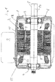
- einen frequenzumrichtergesteuerten Elektromotor gemäß der Erfindung in stark vereinfachter Längsschnittdarstellung,
- Fig. 2
- den Motor gemäß
Fig. 1 in Explosionsdarstellung, - Fig. 3
- die Einzelheit III in
Fig. 2 in vergrößerter Darstellung, - Fig. 4
- den Statorkern in axialer Ansicht,
- Fig. 5
- eine vergrößerte Darstellung der Einzelheit der
Fig. 4 , - Fig. 6
- einen Abschirmring in Explosionsdarstellung,
- Fig. 7
- eine Einzelheit des Abschirmrings in Ansicht,
- Fig. 8
- ein die eigentliche Abschirmung bildendes Metallteil des Abschirmrings gemäß
Fig. 6 in Abwicklung, - Fig. 9
- eine Kurve, welche die kapazitive Kopplung in Abhängigkeit der radialen Tiefe des nutfreien Raums zeigt und
- Fig. 10
- eine Kurve, welche die Abhängigkeit der kapazitiven Kopplung in Abhängigkeit der Höhe des Abschirmrings bezogen auf die Höhe des Wicklungskopfes darstellt.
- Fig. 1
- a frequency converter controlled electric motor according to the invention in a highly simplified longitudinal sectional view,
- Fig. 2
- the engine according to
Fig. 1 in exploded view, - Fig. 3
- the detail III in
Fig. 2 in an enlarged view, - Fig. 4
- the stator core in axial view,
- Fig. 5
- an enlarged view of the detail of
Fig. 4 . - Fig. 6
- a shielding ring in exploded view,
- Fig. 7
- a detail of the shielding ring in view,
- Fig. 8
- a the actual shield forming metal part of the shield according to
Fig. 6 in execution, - Fig. 9
- a curve showing the capacitive coupling as a function of the radial depth of the groove-free space and
- Fig. 10
- a curve showing the dependence of the capacitive coupling as a function of the height of the shielding ring relative to the height of the winding head.
Bei dem anhand von
Wie die Explosionszeichnung gemäß
Bei dem dargestellten Motor handelt es sich um einen Permanentmagnetmotor, der über einen dem Motor vorgeschalteten Frequenzumrichter 7, der am Motorgehäuse 1 angebracht ist, angesteuert wird. Der Rotor 6 weist ein Rotorblechpaket 8 auf, in dem Magnete 9 eingegliedert sind. In der dargestellten Ausführungsform ist das Blechpaket hälftig geteilt, wobei die Magnete 9 der beiden Hälften einen gewissen Winkelversatz aufweisen. Das Rotorblechpaket 8 mit den Magneten 9 ist fest mit der Welle 5 verbunden und drehbar innerhalb des Stators 2 angeordent, welcher einen Statorkern 10 in Form eines Statorblechpaketes 10 aufweist, in den Motorwicklungen 11 angeorndet sind. Zwischen den Wicklungsköpfen 12 der Motorwicklungen 11 und dem Rotor 6, ist in axialer Fortsetzung des Statorkerns 10 zu beiden Seiten ein Abschirmring 13 angeordnet. Die Abschirmringe 13 in Verbindung mit den im nachfolgenden noch beschriebenen Nut-/Wicklungsausbildungen stellen eine kapazitive Abschirmung dar und verhindern, die Einkoppelung hochfrequenter Ströme, wie sie im Frequenzumrichter 7 typischerweise als Oberwellen entstehen, die von den Statorwicklungen 11 in den Rotor 6 induziert werden und dort über die Lager 3, 4 in das Motorgehäuse 1 abfließen und kurzgeschlossen werden. Um diese insbesondere für Oberflächen der Wälzkörper in den Lagern 3, 4 schädlichen Ströme zu verhindern, sind bei dem beschriebenen Motor entsprechende Abschirmmaßnahmen getroffen.In the illustrated motor is a permanent magnet motor, which is controlled via a motor
Diese Abschirmmaßnahmen betreffen zum einen die Anordnung der Motorwicklungen 11 in den Nuten 14 des Statorkerns 10 sowie die Anordnung der Abschirmringe 13.These shielding measures relate, on the one hand, to the arrangement of the
Der Statorkern 10 mit den in den Statornuten 14 angeordneten Motorwicklungen 11 ist in
Die Anordnung der Motorwicklungen 11 im Bereich der Statornuten 14 ist anhand der
An der Innenseite ist jede Nut 14 mit einer Nutisolierung 24 ausgekleidet, welche die in der Nut 14 befindliche Wicklung vollständig umschließt und gegenüber dem metallischen Blechpaket 10 elektrisch isoliert und schützt. Die Nutisolierung 24 besteht aus zwei im Wesentlichen U-förmigen Isolierungsteilen 25 und 26. Der Nutisolierungsteil 25 erstreckt sich über den Nutgrund 21 bis nahe zu den Vorsprüngen 22 längs der seitlichen Wände 20. Der andere Teil 26 der Nutisolierung 24 erstreckt sich vom radial inneren Ende der Wicklung mit Abstand zu den Vorsprüngen 22 bzw. dem dazwischen gebildeten Spalt 23 über etwa ein Drittel der Länge der seitlichen Wände 20. Die Nutisolierungsteile 26 und 25 überlappen einander und greifen ineinander, wie dies anhand von
Bei der vorliegenden Motorkonstruktion sind die Motorwicklungen 11 nicht nutfüllend im Statorkern 11 angeordnet, sondern, wie weiter oben beschrieben, in Richtung zum Nutgrund 21 derart verschoben, dass ein Freiraum 27 gebildet ist, der wicklungsfrei ist. Durch diese Anordnung ist erreicht, dass die Motorwicklungen 11 mit einem radialen Abstand 28 zum Spaltende bzw. zur Innenseite der Vorsprünge 22 angeordnet sind. Dadurch ergibt sich ein freier Abstand zum Rotor 6, der wesentlich für die kapazitive Abschirmung in diesem Bereich ist.In the present motor design, the
Anhand von
Fertigungstechnisch einfach können die Motorwicklungen 11 in konventioneller Weise erzeugt werden, in dem der Wicklungsdraht über Spalten 23 in die jeweiligen Nuten gewickelt wird, bis diese einen nahezu vollständigen Füllgrad erhalten haben. So dann wird durch ein Werkzeug nach Aufheizen der Wicklung auf eine Verbacktemperatur, in welcher der Wicklungslack angeschmolzen wird, diese vom Spalt 23 aus radial nach außen zusammengeschoben. Die Kraftaufbringung erfolgt über ein Werkzeug, welches nicht unmittelbar an der Wicklung angreift, sondern über den inneren Teil 26 der Nutisolierung 24, wodurch die Wicklung selbst vor dem Werkzeug geschützt wird. Nachdem die Motorwicklung in der Nut 14 auf das gewünschte Maß zusammengeschoben worden ist und so der gewünschte Freiraum 27 mit dem Abstand 28 erzeugt worden ist, wird die Wicklung soweit abgekühlt, dass keinerlei Rückstellkräfte mehr auftreten und die Anordnung eigenstabil verbleibt. Bereits dann können weitere Fertigungsschritte eingeleitet werden, bevor die Wicklung auf Umgebungstemperatur zurückgekühlt ist.In terms of manufacturing technology, the
Um auch die Wicklungsköpfe 12 wirksam kapazitiv abzuschirmen, sind Abschirmringe 13 vorgesehen. Diese Abschirmringe 13 bestehen jeweils aus einem aus Kunststoff bestehenden Außenring 29, einem aus Kunststoff bestehenden Innenring 30 sowie der eigentlichen Abschirmung in Form eines metallischen Rings 31. Der Innenring 30 und Außenring 29 sind durch elastische Zungen 32 miteinander klippbefestigbar, wobei der metallische Ring 31 zwischen diesen Ringen 29 und 30 eingegliedert ist. Der metallische Ring 31 ist aus einem Stanzteil in Form eines Blechstreifens 33 gebildet, welches durch Biegen in die ringförmige Form gebracht ist. Das Blechteil 33, welches in
Die Innen- und Außenringe 29, 30 weisen an ihren axialen Enden Vorsprünge 34 auf, die jeweils in Dreiergruppen in gleichem Abstand über den Ring umfangsmäßig verteilt angeordnet sind. Die Anordnung ist derart, dass diese Dreiergruppen von Vorsprüngen 34 bei zusammengeklippten Außen- und Innenring 29, 30 nebeneinander, das heißt radial in Flucht zueinander liegen. Auch der metallische Ring 31 weist Vorsprünge 35 auf, jedoch zu jeder Dreiergruppe der Vorsprünge 34 jeweils nur einen Vorsprung 35. Während die Vorsprünge 34 an den Kunststoffringen 29 und 30 eine gerundete Form aufweisen, wie dies insbesondere aus
Grundsätzlich kann der Abschirmring 13 auch in anderer Weise elektrisch mit dem Statorkern 10 verbunden werden, es müssen jedoch zu einer wirksamen Abschirmung mindestens vier über den Umfang möglichst gleich verteilte elektrische Verbindungen geschaffen werden, um eine wirksame Abschirmung gegen hochfrequente Ströme sicherzustellen.In principle, the shielding
Der Abschirmring 13 muss sich zur wirksamen kapazitiven Entkopplung nicht notwendigerweise über die gesamte axiale Länge 36 eines Wicklungskopfes 12 erstrecken, es genügt vielmehr, eine axiale Länge 37 die deutlich geringer ist. Der Zusammenhang zwischen diesen Größen ist anhand von
- 11
- Motorgehäusemotor housing
- 22
- Statorstator
- 33
- Kugellagerball-bearing
- 44
- Kugellagerball-bearing
- 55
- Wellewave
- 66
- Rotorrotor
- 77
- Frequenzumrichterfrequency converter
- 88th
- RotorblechpaketLaminated core
- 99
- Magnetemagnets
- 1010
- Statorkern, StatorblechpaketStator core, laminated stator core
- 1111
- MotowicklungenMoto windings
- 1212
- Wicklungsköpfewinding heads
- 1313
- Abschirmringshielding
- 1414
- Statornutenstator
- 1515
- zylindrischer Gehäuseteilcylindrical housing part
- 1616
- Deckelcover
- 1717
- Lüfterradfan
- 1818
- Lüfterhaubefan cover
- 1919
- Motorachsemotor axis
- 2020
- seitliche Nutwandungenlateral groove walls
- 2121
- Nutgrundgroove base
- 2222
- Vorsprünge der NutProjections of the groove
- 2323
-
Spalt zwischen den Vorsprüngen 22Gap between the
projections 22 - 2424
- Nutisolierungslot insulation
- 2525
- radial äußerer Teil der Nutisolierungradially outer part of the slot insulation
- 2626
- radial innerer Teil der Nutisolierungradially inner part of the slot insulation
- 2727
- Freiraumfree space
- 2828
-
radialer Abstand zwischen Wicklung und dem Spalt 23/ den Vorsprüngen 22radial distance between the winding and the
gap 23 / the projections 22nd - 2929
- Außenringouter ring
- 3030
- Innenringinner ring
- 3131
- metallischer Ringmetallic ring
- 3232
- elastische Zungenelastic tongues
- 3333
- Blechstreifenmetal strip
- 3434
- Vorsprünge am Außen- und InnenringProjections on the outer and inner ring
- 3535
- Vorsprünge am metallischen RingProjections on the metallic ring
- 3636
- axiale Länge von 12axial length of 12
- 3737
- axiale Länge von 13axial length of 13
Claims (17)
Priority Applications (1)
| Application Number | Priority Date | Filing Date | Title |
|---|---|---|---|
| EP15202549.0A EP3185405B1 (en) | 2015-12-23 | 2015-12-23 | Electric motor |
Applications Claiming Priority (1)
| Application Number | Priority Date | Filing Date | Title |
|---|---|---|---|
| EP15202549.0A EP3185405B1 (en) | 2015-12-23 | 2015-12-23 | Electric motor |
Publications (2)
| Publication Number | Publication Date |
|---|---|
| EP3185405A1 true EP3185405A1 (en) | 2017-06-28 |
| EP3185405B1 EP3185405B1 (en) | 2018-10-31 |
Family
ID=55024940
Family Applications (1)
| Application Number | Title | Priority Date | Filing Date |
|---|---|---|---|
| EP15202549.0A Active EP3185405B1 (en) | 2015-12-23 | 2015-12-23 | Electric motor |
Country Status (1)
| Country | Link |
|---|---|
| EP (1) | EP3185405B1 (en) |
Cited By (1)
| Publication number | Priority date | Publication date | Assignee | Title |
|---|---|---|---|---|
| DE102022003197A1 (en) | 2022-09-01 | 2022-10-27 | Mercedes-Benz Group AG | Electrical machine, in particular for a motor vehicle |
Citations (5)
| Publication number | Priority date | Publication date | Assignee | Title |
|---|---|---|---|---|
| US5821652A (en) * | 1996-08-28 | 1998-10-13 | Marathon Electric Manufacturing Corporation | Dynamoelectric machines with shaft voltage prevention method and structure |
| US5979087A (en) * | 1998-01-16 | 1999-11-09 | Reliance Electric Industrial Company | Electric motor having electrostatic shield arrangement |
| JP2003180044A (en) * | 2001-12-07 | 2003-06-27 | Okuma Corp | Stator and its manufacturing method |
| US20040056538A1 (en) * | 2001-01-09 | 2004-03-25 | Du Hung T. | Dynamoelectric machine having an encapsulated coil structure |
| WO2014002545A1 (en) * | 2012-06-29 | 2014-01-03 | アイシン・エィ・ダブリュ株式会社 | Method for manufacturing linear conductor, and method for manufacturing rotating electrical machine |
-
2015
- 2015-12-23 EP EP15202549.0A patent/EP3185405B1/en active Active
Patent Citations (5)
| Publication number | Priority date | Publication date | Assignee | Title |
|---|---|---|---|---|
| US5821652A (en) * | 1996-08-28 | 1998-10-13 | Marathon Electric Manufacturing Corporation | Dynamoelectric machines with shaft voltage prevention method and structure |
| US5979087A (en) * | 1998-01-16 | 1999-11-09 | Reliance Electric Industrial Company | Electric motor having electrostatic shield arrangement |
| US20040056538A1 (en) * | 2001-01-09 | 2004-03-25 | Du Hung T. | Dynamoelectric machine having an encapsulated coil structure |
| JP2003180044A (en) * | 2001-12-07 | 2003-06-27 | Okuma Corp | Stator and its manufacturing method |
| WO2014002545A1 (en) * | 2012-06-29 | 2014-01-03 | アイシン・エィ・ダブリュ株式会社 | Method for manufacturing linear conductor, and method for manufacturing rotating electrical machine |
Non-Patent Citations (1)
| Title |
|---|
| MAGDUN O ET AL: "Prevention of harmful EDM currents in inverter-fed AC machines by use of electrostatic shields in the stator winding overhang", IECON 2010 - 36TH ANNUAL CONFERENCE ON IEEE INDUSTRIAL ELECTRONICS SOCIETY, IEEE, PISCATAWAY, NJ, USA, 7 November 2010 (2010-11-07), pages 962 - 967, XP031840554, ISBN: 978-1-4244-5225-5 * |
Cited By (1)
| Publication number | Priority date | Publication date | Assignee | Title |
|---|---|---|---|---|
| DE102022003197A1 (en) | 2022-09-01 | 2022-10-27 | Mercedes-Benz Group AG | Electrical machine, in particular for a motor vehicle |
Also Published As
| Publication number | Publication date |
|---|---|
| EP3185405B1 (en) | 2018-10-31 |
Similar Documents
| Publication | Publication Date | Title |
|---|---|---|
| WO2020099048A1 (en) | Support device for a rotor of a separately excited internal-rotor synchronous machine consisting of a support ring and a star disc | |
| DE102015225088A1 (en) | Engine and method of making same | |
| DE112014004639B4 (en) | Rotating electrical machine and manufacturing process therefor | |
| WO1990009697A1 (en) | A permanent-magnet-excited electric motor | |
| DE102011083128A1 (en) | electric motor | |
| DE112005000944T5 (en) | Brushless motor | |
| EP3127223B1 (en) | Electric machine | |
| DE102013219186A1 (en) | Electric machine and connection unit for electric machine. | |
| DE102012100332A1 (en) | Stator for a rotating electrical machine and method for its manufacture | |
| EP2541740B1 (en) | Stator | |
| WO2016066389A2 (en) | Rotor of an electric machine, electric machine, and method for producing a rotor of an electric machine | |
| WO2019110275A1 (en) | Electrical machine, in particular for a vehicle | |
| WO2019002289A1 (en) | Electrical machine, in particular for a vehicle | |
| WO2019110271A1 (en) | Electric machine, in particular for a vehicle | |
| DE112017006320T5 (en) | STATOR CORE FOR AN ELECTRICAL ROTATION MACHINE AND RELATED MANUFACTURING METHOD | |
| WO2017012707A1 (en) | Core body for stators and/or rotors of electric machines, stator/rotor having a core body of said type, and electric machine having a core body of said type | |
| EP3185405B1 (en) | Electric motor | |
| DE2913844C2 (en) | Slot insulation for the rotor of an electrical machine | |
| EP3012945B1 (en) | Electric machine with a housing | |
| EP0619638A2 (en) | An electrical machine with a disk armature | |
| DE102017207663A1 (en) | Method for producing a coil arrangement | |
| EP3276797A1 (en) | Rotor for an electric rotating machine | |
| DE102004008688B4 (en) | linear motor | |
| WO2018197133A1 (en) | Segmented stator for an electric motor of the internal rotor type | |
| DE102018222354A1 (en) | Basic stator body for an electric motor, stator, electric motor and method for producing the basic stator body |
Legal Events
| Date | Code | Title | Description |
|---|---|---|---|
| PUAI | Public reference made under article 153(3) epc to a published international application that has entered the european phase |
Free format text: ORIGINAL CODE: 0009012 |
|
| STAA | Information on the status of an ep patent application or granted ep patent |
Free format text: STATUS: THE APPLICATION HAS BEEN PUBLISHED |
|
| AK | Designated contracting states |
Kind code of ref document: A1 Designated state(s): AL AT BE BG CH CY CZ DE DK EE ES FI FR GB GR HR HU IE IS IT LI LT LU LV MC MK MT NL NO PL PT RO RS SE SI SK SM TR |
|
| AX | Request for extension of the european patent |
Extension state: BA ME |
|
| STAA | Information on the status of an ep patent application or granted ep patent |
Free format text: STATUS: REQUEST FOR EXAMINATION WAS MADE |
|
| 17P | Request for examination filed |
Effective date: 20171228 |
|
| RBV | Designated contracting states (corrected) |
Designated state(s): AL AT BE BG CH CY CZ DE DK EE ES FI FR GB GR HR HU IE IS IT LI LT LU LV MC MK MT NL NO PL PT RO RS SE SI SK SM TR |
|
| GRAP | Despatch of communication of intention to grant a patent |
Free format text: ORIGINAL CODE: EPIDOSNIGR1 |
|
| STAA | Information on the status of an ep patent application or granted ep patent |
Free format text: STATUS: GRANT OF PATENT IS INTENDED |
|
| RIC1 | Information provided on ipc code assigned before grant |
Ipc: H02K 3/42 20060101ALI20180302BHEP Ipc: H02K 15/00 20060101AFI20180302BHEP Ipc: H02K 3/38 20060101ALI20180302BHEP Ipc: H02K 3/34 20060101ALI20180302BHEP |
|
| INTG | Intention to grant announced |
Effective date: 20180319 |
|
| GRAS | Grant fee paid |
Free format text: ORIGINAL CODE: EPIDOSNIGR3 |
|
| GRAJ | Information related to disapproval of communication of intention to grant by the applicant or resumption of examination proceedings by the epo deleted |
Free format text: ORIGINAL CODE: EPIDOSDIGR1 |
|
| GRAL | Information related to payment of fee for publishing/printing deleted |
Free format text: ORIGINAL CODE: EPIDOSDIGR3 |
|
| STAA | Information on the status of an ep patent application or granted ep patent |
Free format text: STATUS: REQUEST FOR EXAMINATION WAS MADE |
|
| GRAR | Information related to intention to grant a patent recorded |
Free format text: ORIGINAL CODE: EPIDOSNIGR71 |
|
| STAA | Information on the status of an ep patent application or granted ep patent |
Free format text: STATUS: GRANT OF PATENT IS INTENDED |
|
| GRAA | (expected) grant |
Free format text: ORIGINAL CODE: 0009210 |
|
| STAA | Information on the status of an ep patent application or granted ep patent |
Free format text: STATUS: THE PATENT HAS BEEN GRANTED |
|
| INTC | Intention to grant announced (deleted) | ||
| INTG | Intention to grant announced |
Effective date: 20180920 |
|
| AK | Designated contracting states |
Kind code of ref document: B1 Designated state(s): AL AT BE BG CH CY CZ DE DK EE ES FI FR GB GR HR HU IE IS IT LI LT LU LV MC MK MT NL NO PL PT RO RS SE SI SK SM TR |
|
| REG | Reference to a national code |
Ref country code: CH Ref legal event code: EP Ref country code: GB Ref legal event code: FG4D Free format text: NOT ENGLISH |
|
| REG | Reference to a national code |
Ref country code: AT Ref legal event code: REF Ref document number: 1060577 Country of ref document: AT Kind code of ref document: T Effective date: 20181115 |
|
| REG | Reference to a national code |
Ref country code: DE Ref legal event code: R096 Ref document number: 502015006653 Country of ref document: DE |
|
| REG | Reference to a national code |
Ref country code: IE Ref legal event code: FG4D Free format text: LANGUAGE OF EP DOCUMENT: GERMAN |
|
| REG | Reference to a national code |
Ref country code: NL Ref legal event code: MP Effective date: 20181031 |
|
| REG | Reference to a national code |
Ref country code: LT Ref legal event code: MG4D |
|
| PG25 | Lapsed in a contracting state [announced via postgrant information from national office to epo] |
Ref country code: NO Free format text: LAPSE BECAUSE OF FAILURE TO SUBMIT A TRANSLATION OF THE DESCRIPTION OR TO PAY THE FEE WITHIN THE PRESCRIBED TIME-LIMIT Effective date: 20190131 Ref country code: BG Free format text: LAPSE BECAUSE OF FAILURE TO SUBMIT A TRANSLATION OF THE DESCRIPTION OR TO PAY THE FEE WITHIN THE PRESCRIBED TIME-LIMIT Effective date: 20190131 Ref country code: PL Free format text: LAPSE BECAUSE OF FAILURE TO SUBMIT A TRANSLATION OF THE DESCRIPTION OR TO PAY THE FEE WITHIN THE PRESCRIBED TIME-LIMIT Effective date: 20181031 Ref country code: LT Free format text: LAPSE BECAUSE OF FAILURE TO SUBMIT A TRANSLATION OF THE DESCRIPTION OR TO PAY THE FEE WITHIN THE PRESCRIBED TIME-LIMIT Effective date: 20181031 Ref country code: ES Free format text: LAPSE BECAUSE OF FAILURE TO SUBMIT A TRANSLATION OF THE DESCRIPTION OR TO PAY THE FEE WITHIN THE PRESCRIBED TIME-LIMIT Effective date: 20181031 Ref country code: LV Free format text: LAPSE BECAUSE OF FAILURE TO SUBMIT A TRANSLATION OF THE DESCRIPTION OR TO PAY THE FEE WITHIN THE PRESCRIBED TIME-LIMIT Effective date: 20181031 Ref country code: IS Free format text: LAPSE BECAUSE OF FAILURE TO SUBMIT A TRANSLATION OF THE DESCRIPTION OR TO PAY THE FEE WITHIN THE PRESCRIBED TIME-LIMIT Effective date: 20190228 Ref country code: HR Free format text: LAPSE BECAUSE OF FAILURE TO SUBMIT A TRANSLATION OF THE DESCRIPTION OR TO PAY THE FEE WITHIN THE PRESCRIBED TIME-LIMIT Effective date: 20181031 Ref country code: FI Free format text: LAPSE BECAUSE OF FAILURE TO SUBMIT A TRANSLATION OF THE DESCRIPTION OR TO PAY THE FEE WITHIN THE PRESCRIBED TIME-LIMIT Effective date: 20181031 |
|
| PG25 | Lapsed in a contracting state [announced via postgrant information from national office to epo] |
Ref country code: SE Free format text: LAPSE BECAUSE OF FAILURE TO SUBMIT A TRANSLATION OF THE DESCRIPTION OR TO PAY THE FEE WITHIN THE PRESCRIBED TIME-LIMIT Effective date: 20181031 Ref country code: GR Free format text: LAPSE BECAUSE OF FAILURE TO SUBMIT A TRANSLATION OF THE DESCRIPTION OR TO PAY THE FEE WITHIN THE PRESCRIBED TIME-LIMIT Effective date: 20190201 Ref country code: AL Free format text: LAPSE BECAUSE OF FAILURE TO SUBMIT A TRANSLATION OF THE DESCRIPTION OR TO PAY THE FEE WITHIN THE PRESCRIBED TIME-LIMIT Effective date: 20181031 Ref country code: RS Free format text: LAPSE BECAUSE OF FAILURE TO SUBMIT A TRANSLATION OF THE DESCRIPTION OR TO PAY THE FEE WITHIN THE PRESCRIBED TIME-LIMIT Effective date: 20181031 Ref country code: PT Free format text: LAPSE BECAUSE OF FAILURE TO SUBMIT A TRANSLATION OF THE DESCRIPTION OR TO PAY THE FEE WITHIN THE PRESCRIBED TIME-LIMIT Effective date: 20190301 Ref country code: NL Free format text: LAPSE BECAUSE OF FAILURE TO SUBMIT A TRANSLATION OF THE DESCRIPTION OR TO PAY THE FEE WITHIN THE PRESCRIBED TIME-LIMIT Effective date: 20181031 |
|
| PG25 | Lapsed in a contracting state [announced via postgrant information from national office to epo] |
Ref country code: DK Free format text: LAPSE BECAUSE OF FAILURE TO SUBMIT A TRANSLATION OF THE DESCRIPTION OR TO PAY THE FEE WITHIN THE PRESCRIBED TIME-LIMIT Effective date: 20181031 Ref country code: CZ Free format text: LAPSE BECAUSE OF FAILURE TO SUBMIT A TRANSLATION OF THE DESCRIPTION OR TO PAY THE FEE WITHIN THE PRESCRIBED TIME-LIMIT Effective date: 20181031 |
|
| REG | Reference to a national code |
Ref country code: CH Ref legal event code: PL |
|
| REG | Reference to a national code |
Ref country code: DE Ref legal event code: R097 Ref document number: 502015006653 Country of ref document: DE |
|
| PG25 | Lapsed in a contracting state [announced via postgrant information from national office to epo] |
Ref country code: EE Free format text: LAPSE BECAUSE OF FAILURE TO SUBMIT A TRANSLATION OF THE DESCRIPTION OR TO PAY THE FEE WITHIN THE PRESCRIBED TIME-LIMIT Effective date: 20181031 Ref country code: LU Free format text: LAPSE BECAUSE OF NON-PAYMENT OF DUE FEES Effective date: 20181223 Ref country code: RO Free format text: LAPSE BECAUSE OF FAILURE TO SUBMIT A TRANSLATION OF THE DESCRIPTION OR TO PAY THE FEE WITHIN THE PRESCRIBED TIME-LIMIT Effective date: 20181031 Ref country code: SK Free format text: LAPSE BECAUSE OF FAILURE TO SUBMIT A TRANSLATION OF THE DESCRIPTION OR TO PAY THE FEE WITHIN THE PRESCRIBED TIME-LIMIT Effective date: 20181031 Ref country code: MC Free format text: LAPSE BECAUSE OF FAILURE TO SUBMIT A TRANSLATION OF THE DESCRIPTION OR TO PAY THE FEE WITHIN THE PRESCRIBED TIME-LIMIT Effective date: 20181031 Ref country code: SM Free format text: LAPSE BECAUSE OF FAILURE TO SUBMIT A TRANSLATION OF THE DESCRIPTION OR TO PAY THE FEE WITHIN THE PRESCRIBED TIME-LIMIT Effective date: 20181031 |
|
| PLBE | No opposition filed within time limit |
Free format text: ORIGINAL CODE: 0009261 |
|
| STAA | Information on the status of an ep patent application or granted ep patent |
Free format text: STATUS: NO OPPOSITION FILED WITHIN TIME LIMIT |
|
| REG | Reference to a national code |
Ref country code: IE Ref legal event code: MM4A |
|
| REG | Reference to a national code |
Ref country code: BE Ref legal event code: MM Effective date: 20181231 |
|
| 26N | No opposition filed |
Effective date: 20190801 |
|
| PG25 | Lapsed in a contracting state [announced via postgrant information from national office to epo] |
Ref country code: IE Free format text: LAPSE BECAUSE OF NON-PAYMENT OF DUE FEES Effective date: 20181223 Ref country code: SI Free format text: LAPSE BECAUSE OF FAILURE TO SUBMIT A TRANSLATION OF THE DESCRIPTION OR TO PAY THE FEE WITHIN THE PRESCRIBED TIME-LIMIT Effective date: 20181031 |
|
| PG25 | Lapsed in a contracting state [announced via postgrant information from national office to epo] |
Ref country code: BE Free format text: LAPSE BECAUSE OF NON-PAYMENT OF DUE FEES Effective date: 20181231 |
|
| PG25 | Lapsed in a contracting state [announced via postgrant information from national office to epo] |
Ref country code: CH Free format text: LAPSE BECAUSE OF NON-PAYMENT OF DUE FEES Effective date: 20181231 Ref country code: LI Free format text: LAPSE BECAUSE OF NON-PAYMENT OF DUE FEES Effective date: 20181231 |
|
| PG25 | Lapsed in a contracting state [announced via postgrant information from national office to epo] |
Ref country code: MT Free format text: LAPSE BECAUSE OF FAILURE TO SUBMIT A TRANSLATION OF THE DESCRIPTION OR TO PAY THE FEE WITHIN THE PRESCRIBED TIME-LIMIT Effective date: 20181031 |
|
| PG25 | Lapsed in a contracting state [announced via postgrant information from national office to epo] |
Ref country code: TR Free format text: LAPSE BECAUSE OF FAILURE TO SUBMIT A TRANSLATION OF THE DESCRIPTION OR TO PAY THE FEE WITHIN THE PRESCRIBED TIME-LIMIT Effective date: 20181031 |
|
| PG25 | Lapsed in a contracting state [announced via postgrant information from national office to epo] |
Ref country code: MK Free format text: LAPSE BECAUSE OF NON-PAYMENT OF DUE FEES Effective date: 20181031 Ref country code: CY Free format text: LAPSE BECAUSE OF FAILURE TO SUBMIT A TRANSLATION OF THE DESCRIPTION OR TO PAY THE FEE WITHIN THE PRESCRIBED TIME-LIMIT Effective date: 20181031 Ref country code: HU Free format text: LAPSE BECAUSE OF FAILURE TO SUBMIT A TRANSLATION OF THE DESCRIPTION OR TO PAY THE FEE WITHIN THE PRESCRIBED TIME-LIMIT; INVALID AB INITIO Effective date: 20151223 |
|
| REG | Reference to a national code |
Ref country code: AT Ref legal event code: MM01 Ref document number: 1060577 Country of ref document: AT Kind code of ref document: T Effective date: 20201223 |
|
| PG25 | Lapsed in a contracting state [announced via postgrant information from national office to epo] |
Ref country code: AT Free format text: LAPSE BECAUSE OF NON-PAYMENT OF DUE FEES Effective date: 20201223 |
|
| REG | Reference to a national code |
Ref country code: DE Ref legal event code: R082 Ref document number: 502015006653 Country of ref document: DE |
|
| PGFP | Annual fee paid to national office [announced via postgrant information from national office to epo] |
Ref country code: GB Payment date: 20231220 Year of fee payment: 9 |
|
| PGFP | Annual fee paid to national office [announced via postgrant information from national office to epo] |
Ref country code: IT Payment date: 20231228 Year of fee payment: 9 Ref country code: FR Payment date: 20231221 Year of fee payment: 9 Ref country code: DE Payment date: 20231214 Year of fee payment: 9 |