EP3185342A1 - Electrode catalyst for fuel cells - Google Patents
Electrode catalyst for fuel cells Download PDFInfo
- Publication number
- EP3185342A1 EP3185342A1 EP16206628.6A EP16206628A EP3185342A1 EP 3185342 A1 EP3185342 A1 EP 3185342A1 EP 16206628 A EP16206628 A EP 16206628A EP 3185342 A1 EP3185342 A1 EP 3185342A1
- Authority
- EP
- European Patent Office
- Prior art keywords
- catalyst
- fuel cells
- pore
- electrode catalyst
- anode
- Prior art date
- Legal status (The legal status is an assumption and is not a legal conclusion. Google has not performed a legal analysis and makes no representation as to the accuracy of the status listed.)
- Pending
Links
- 239000003054 catalyst Substances 0.000 title claims abstract description 241
- 239000000446 fuel Substances 0.000 title claims abstract description 111
- 239000011148 porous material Substances 0.000 claims abstract description 135
- 239000002245 particle Substances 0.000 claims abstract description 123
- OKTJSMMVPCPJKN-UHFFFAOYSA-N Carbon Chemical compound [C] OKTJSMMVPCPJKN-UHFFFAOYSA-N 0.000 claims abstract description 108
- 229910052799 carbon Inorganic materials 0.000 claims abstract description 107
- BASFCYQUMIYNBI-UHFFFAOYSA-N platinum Chemical compound [Pt] BASFCYQUMIYNBI-UHFFFAOYSA-N 0.000 claims description 51
- 229910052697 platinum Inorganic materials 0.000 claims description 18
- 230000002401 inhibitory effect Effects 0.000 abstract description 2
- 230000000052 comparative effect Effects 0.000 description 31
- 229910052751 metal Inorganic materials 0.000 description 29
- 239000002184 metal Substances 0.000 description 29
- 238000009792 diffusion process Methods 0.000 description 27
- 239000000843 powder Substances 0.000 description 26
- 238000001354 calcination Methods 0.000 description 21
- 238000006722 reduction reaction Methods 0.000 description 17
- 238000000034 method Methods 0.000 description 16
- IJGRMHOSHXDMSA-UHFFFAOYSA-N Atomic nitrogen Chemical compound N#N IJGRMHOSHXDMSA-UHFFFAOYSA-N 0.000 description 13
- NWAHZABTSDUXMJ-UHFFFAOYSA-N platinum(2+);dinitrate Chemical compound [Pt+2].[O-][N+]([O-])=O.[O-][N+]([O-])=O NWAHZABTSDUXMJ-UHFFFAOYSA-N 0.000 description 13
- LFQSCWFLJHTTHZ-UHFFFAOYSA-N Ethanol Chemical compound CCO LFQSCWFLJHTTHZ-UHFFFAOYSA-N 0.000 description 10
- 239000000463 material Substances 0.000 description 10
- 150000003839 salts Chemical class 0.000 description 10
- 238000009826 distribution Methods 0.000 description 9
- 239000007787 solid Substances 0.000 description 8
- 239000006185 dispersion Substances 0.000 description 7
- 238000010438 heat treatment Methods 0.000 description 7
- 239000007769 metal material Substances 0.000 description 7
- 238000002360 preparation method Methods 0.000 description 7
- 229910001260 Pt alloy Inorganic materials 0.000 description 6
- 238000002441 X-ray diffraction Methods 0.000 description 6
- 239000007788 liquid Substances 0.000 description 6
- XLYOFNOQVPJJNP-UHFFFAOYSA-N water Substances O XLYOFNOQVPJJNP-UHFFFAOYSA-N 0.000 description 6
- 229910001873 dinitrogen Inorganic materials 0.000 description 5
- 230000000694 effects Effects 0.000 description 5
- 230000014509 gene expression Effects 0.000 description 5
- 229920000554 ionomer Polymers 0.000 description 5
- 230000037361 pathway Effects 0.000 description 5
- PXHVJJICTQNCMI-UHFFFAOYSA-N Nickel Chemical compound [Ni] PXHVJJICTQNCMI-UHFFFAOYSA-N 0.000 description 4
- KDLHZDBZIXYQEI-UHFFFAOYSA-N Palladium Chemical compound [Pd] KDLHZDBZIXYQEI-UHFFFAOYSA-N 0.000 description 4
- 238000006243 chemical reaction Methods 0.000 description 4
- 239000010949 copper Substances 0.000 description 4
- 230000007423 decrease Effects 0.000 description 4
- 239000010419 fine particle Substances 0.000 description 4
- 229910052757 nitrogen Inorganic materials 0.000 description 4
- QTBSBXVTEAMEQO-UHFFFAOYSA-N Acetic acid Chemical compound CC(O)=O QTBSBXVTEAMEQO-UHFFFAOYSA-N 0.000 description 3
- KFZMGEQAYNKOFK-UHFFFAOYSA-N Isopropanol Chemical compound CC(C)O KFZMGEQAYNKOFK-UHFFFAOYSA-N 0.000 description 3
- OKKJLVBELUTLKV-UHFFFAOYSA-N Methanol Chemical compound OC OKKJLVBELUTLKV-UHFFFAOYSA-N 0.000 description 3
- 230000015572 biosynthetic process Effects 0.000 description 3
- 239000006229 carbon black Substances 0.000 description 3
- 239000010432 diamond Substances 0.000 description 3
- 239000010931 gold Substances 0.000 description 3
- 239000001257 hydrogen Substances 0.000 description 3
- 229910052739 hydrogen Inorganic materials 0.000 description 3
- 239000011572 manganese Substances 0.000 description 3
- 238000004519 manufacturing process Methods 0.000 description 3
- 239000010955 niobium Substances 0.000 description 3
- 239000010936 titanium Substances 0.000 description 3
- VHUUQVKOLVNVRT-UHFFFAOYSA-N Ammonium hydroxide Chemical compound [NH4+].[OH-] VHUUQVKOLVNVRT-UHFFFAOYSA-N 0.000 description 2
- OAKJQQAXSVQMHS-UHFFFAOYSA-N Hydrazine Chemical compound NN OAKJQQAXSVQMHS-UHFFFAOYSA-N 0.000 description 2
- UFHFLCQGNIYNRP-UHFFFAOYSA-N Hydrogen Chemical compound [H][H] UFHFLCQGNIYNRP-UHFFFAOYSA-N 0.000 description 2
- 229920000557 Nafion® Polymers 0.000 description 2
- NBIIXXVUZAFLBC-UHFFFAOYSA-N Phosphoric acid Chemical compound OP(O)(O)=O NBIIXXVUZAFLBC-UHFFFAOYSA-N 0.000 description 2
- 235000011114 ammonium hydroxide Nutrition 0.000 description 2
- QZPSXPBJTPJTSZ-UHFFFAOYSA-N aqua regia Chemical compound Cl.O[N+]([O-])=O QZPSXPBJTPJTSZ-UHFFFAOYSA-N 0.000 description 2
- QVGXLLKOCUKJST-UHFFFAOYSA-N atomic oxygen Chemical compound [O] QVGXLLKOCUKJST-UHFFFAOYSA-N 0.000 description 2
- 239000011248 coating agent Substances 0.000 description 2
- 238000000576 coating method Methods 0.000 description 2
- 229910052802 copper Inorganic materials 0.000 description 2
- 238000011156 evaluation Methods 0.000 description 2
- 229910052737 gold Inorganic materials 0.000 description 2
- XLYOFNOQVPJJNP-UHFFFAOYSA-M hydroxide Chemical compound [OH-] XLYOFNOQVPJJNP-UHFFFAOYSA-M 0.000 description 2
- 238000009616 inductively coupled plasma Methods 0.000 description 2
- 229910052748 manganese Inorganic materials 0.000 description 2
- 229910052759 nickel Inorganic materials 0.000 description 2
- 238000007254 oxidation reaction Methods 0.000 description 2
- 239000001301 oxygen Substances 0.000 description 2
- 229910052760 oxygen Inorganic materials 0.000 description 2
- 229910052763 palladium Inorganic materials 0.000 description 2
- 238000010248 power generation Methods 0.000 description 2
- 238000001179 sorption measurement Methods 0.000 description 2
- 239000000725 suspension Substances 0.000 description 2
- 229910052715 tantalum Inorganic materials 0.000 description 2
- 229910052719 titanium Inorganic materials 0.000 description 2
- 239000011800 void material Substances 0.000 description 2
- BVKZGUZCCUSVTD-UHFFFAOYSA-L Carbonate Chemical compound [O-]C([O-])=O BVKZGUZCCUSVTD-UHFFFAOYSA-L 0.000 description 1
- 229910052684 Cerium Inorganic materials 0.000 description 1
- RYGMFSIKBFXOCR-UHFFFAOYSA-N Copper Chemical compound [Cu] RYGMFSIKBFXOCR-UHFFFAOYSA-N 0.000 description 1
- 229910052688 Gadolinium Inorganic materials 0.000 description 1
- XEEYBQQBJWHFJM-UHFFFAOYSA-N Iron Chemical compound [Fe] XEEYBQQBJWHFJM-UHFFFAOYSA-N 0.000 description 1
- PWHULOQIROXLJO-UHFFFAOYSA-N Manganese Chemical compound [Mn] PWHULOQIROXLJO-UHFFFAOYSA-N 0.000 description 1
- 229910002651 NO3 Inorganic materials 0.000 description 1
- GRYLNZFGIOXLOG-UHFFFAOYSA-N Nitric acid Chemical compound O[N+]([O-])=O GRYLNZFGIOXLOG-UHFFFAOYSA-N 0.000 description 1
- 238000003917 TEM image Methods 0.000 description 1
- 239000004809 Teflon Substances 0.000 description 1
- 229920006362 Teflon® Polymers 0.000 description 1
- RTAQQCXQSZGOHL-UHFFFAOYSA-N Titanium Chemical compound [Ti] RTAQQCXQSZGOHL-UHFFFAOYSA-N 0.000 description 1
- MQRWBMAEBQOWAF-UHFFFAOYSA-N acetic acid;nickel Chemical compound [Ni].CC(O)=O.CC(O)=O MQRWBMAEBQOWAF-UHFFFAOYSA-N 0.000 description 1
- 239000006230 acetylene black Substances 0.000 description 1
- 230000002378 acidificating effect Effects 0.000 description 1
- 229910000147 aluminium phosphate Inorganic materials 0.000 description 1
- FEVAROJZEMZJGB-UHFFFAOYSA-L azane;palladium(2+);dinitrite Chemical compound N.N.[Pd+2].[O-]N=O.[O-]N=O FEVAROJZEMZJGB-UHFFFAOYSA-L 0.000 description 1
- 230000005540 biological transmission Effects 0.000 description 1
- 238000009835 boiling Methods 0.000 description 1
- GWXLDORMOJMVQZ-UHFFFAOYSA-N cerium Chemical compound [Ce] GWXLDORMOJMVQZ-UHFFFAOYSA-N 0.000 description 1
- 239000003638 chemical reducing agent Substances 0.000 description 1
- 229910017052 cobalt Inorganic materials 0.000 description 1
- 239000010941 cobalt Substances 0.000 description 1
- 229940011182 cobalt acetate Drugs 0.000 description 1
- GUTLYIVDDKVIGB-UHFFFAOYSA-N cobalt atom Chemical compound [Co] GUTLYIVDDKVIGB-UHFFFAOYSA-N 0.000 description 1
- UFMZWBIQTDUYBN-UHFFFAOYSA-N cobalt dinitrate Chemical compound [Co+2].[O-][N+]([O-])=O.[O-][N+]([O-])=O UFMZWBIQTDUYBN-UHFFFAOYSA-N 0.000 description 1
- 229910001981 cobalt nitrate Inorganic materials 0.000 description 1
- QAHREYKOYSIQPH-UHFFFAOYSA-L cobalt(II) acetate Chemical compound [Co+2].CC([O-])=O.CC([O-])=O QAHREYKOYSIQPH-UHFFFAOYSA-L 0.000 description 1
- 238000000366 colloid method Methods 0.000 description 1
- 239000013078 crystal Substances 0.000 description 1
- 230000003247 decreasing effect Effects 0.000 description 1
- 230000005611 electricity Effects 0.000 description 1
- 238000003487 electrochemical reaction Methods 0.000 description 1
- 239000003792 electrolyte Substances 0.000 description 1
- 238000005516 engineering process Methods 0.000 description 1
- 238000002474 experimental method Methods 0.000 description 1
- 239000012530 fluid Substances 0.000 description 1
- 239000002737 fuel gas Substances 0.000 description 1
- 125000000524 functional group Chemical group 0.000 description 1
- UIWYJDYFSGRHKR-UHFFFAOYSA-N gadolinium atom Chemical compound [Gd] UIWYJDYFSGRHKR-UHFFFAOYSA-N 0.000 description 1
- 239000007789 gas Substances 0.000 description 1
- PCHJSUWPFVWCPO-UHFFFAOYSA-N gold Chemical compound [Au] PCHJSUWPFVWCPO-UHFFFAOYSA-N 0.000 description 1
- 238000007731 hot pressing Methods 0.000 description 1
- 150000002431 hydrogen Chemical class 0.000 description 1
- 238000005470 impregnation Methods 0.000 description 1
- 238000002354 inductively-coupled plasma atomic emission spectroscopy Methods 0.000 description 1
- 150000002500 ions Chemical class 0.000 description 1
- 229910052741 iridium Inorganic materials 0.000 description 1
- GKOZUEZYRPOHIO-UHFFFAOYSA-N iridium atom Chemical compound [Ir] GKOZUEZYRPOHIO-UHFFFAOYSA-N 0.000 description 1
- 229910052747 lanthanoid Inorganic materials 0.000 description 1
- 150000002602 lanthanoids Chemical class 0.000 description 1
- 229910052746 lanthanum Inorganic materials 0.000 description 1
- FZLIPJUXYLNCLC-UHFFFAOYSA-N lanthanum atom Chemical compound [La] FZLIPJUXYLNCLC-UHFFFAOYSA-N 0.000 description 1
- 230000007774 longterm Effects 0.000 description 1
- 229940071125 manganese acetate Drugs 0.000 description 1
- UOGMEBQRZBEZQT-UHFFFAOYSA-L manganese(2+);diacetate Chemical compound [Mn+2].CC([O-])=O.CC([O-])=O UOGMEBQRZBEZQT-UHFFFAOYSA-L 0.000 description 1
- MIVBAHRSNUNMPP-UHFFFAOYSA-N manganese(2+);dinitrate Chemical compound [Mn+2].[O-][N+]([O-])=O.[O-][N+]([O-])=O MIVBAHRSNUNMPP-UHFFFAOYSA-N 0.000 description 1
- 239000012528 membrane Substances 0.000 description 1
- 229910021645 metal ion Inorganic materials 0.000 description 1
- 239000000203 mixture Substances 0.000 description 1
- 229940078494 nickel acetate Drugs 0.000 description 1
- KBJMLQFLOWQJNF-UHFFFAOYSA-N nickel(ii) nitrate Chemical compound [Ni+2].[O-][N+]([O-])=O.[O-][N+]([O-])=O KBJMLQFLOWQJNF-UHFFFAOYSA-N 0.000 description 1
- 229910052758 niobium Inorganic materials 0.000 description 1
- GUCVJGMIXFAOAE-UHFFFAOYSA-N niobium atom Chemical compound [Nb] GUCVJGMIXFAOAE-UHFFFAOYSA-N 0.000 description 1
- 229910017604 nitric acid Inorganic materials 0.000 description 1
- 230000003287 optical effect Effects 0.000 description 1
- 239000007800 oxidant agent Substances 0.000 description 1
- 230000003647 oxidation Effects 0.000 description 1
- 230000001590 oxidative effect Effects 0.000 description 1
- 230000000704 physical effect Effects 0.000 description 1
- 239000005518 polymer electrolyte Substances 0.000 description 1
- 238000001556 precipitation Methods 0.000 description 1
- BDERNNFJNOPAEC-UHFFFAOYSA-N propan-1-ol Chemical compound CCCO BDERNNFJNOPAEC-UHFFFAOYSA-N 0.000 description 1
- 229920006395 saturated elastomer Polymers 0.000 description 1
- 238000004062 sedimentation Methods 0.000 description 1
- 239000012279 sodium borohydride Substances 0.000 description 1
- 229910000033 sodium borohydride Inorganic materials 0.000 description 1
- 239000007858 starting material Substances 0.000 description 1
- GUVRBAGPIYLISA-UHFFFAOYSA-N tantalum atom Chemical compound [Ta] GUVRBAGPIYLISA-UHFFFAOYSA-N 0.000 description 1
- 238000002604 ultrasonography Methods 0.000 description 1
- 229910052727 yttrium Inorganic materials 0.000 description 1
- VWQVUPCCIRVNHF-UHFFFAOYSA-N yttrium atom Chemical compound [Y] VWQVUPCCIRVNHF-UHFFFAOYSA-N 0.000 description 1
Images

Classifications
-
- H—ELECTRICITY
- H01—ELECTRIC ELEMENTS
- H01M—PROCESSES OR MEANS, e.g. BATTERIES, FOR THE DIRECT CONVERSION OF CHEMICAL ENERGY INTO ELECTRICAL ENERGY
- H01M4/00—Electrodes
- H01M4/86—Inert electrodes with catalytic activity, e.g. for fuel cells
-
- H—ELECTRICITY
- H01—ELECTRIC ELEMENTS
- H01M—PROCESSES OR MEANS, e.g. BATTERIES, FOR THE DIRECT CONVERSION OF CHEMICAL ENERGY INTO ELECTRICAL ENERGY
- H01M4/00—Electrodes
- H01M4/86—Inert electrodes with catalytic activity, e.g. for fuel cells
- H01M4/90—Selection of catalytic material
- H01M4/92—Metals of platinum group
- H01M4/925—Metals of platinum group supported on carriers, e.g. powder carriers
- H01M4/926—Metals of platinum group supported on carriers, e.g. powder carriers on carbon or graphite
-
- H—ELECTRICITY
- H01—ELECTRIC ELEMENTS
- H01M—PROCESSES OR MEANS, e.g. BATTERIES, FOR THE DIRECT CONVERSION OF CHEMICAL ENERGY INTO ELECTRICAL ENERGY
- H01M4/00—Electrodes
- H01M4/86—Inert electrodes with catalytic activity, e.g. for fuel cells
- H01M4/90—Selection of catalytic material
- H01M4/9075—Catalytic material supported on carriers, e.g. powder carriers
- H01M4/9083—Catalytic material supported on carriers, e.g. powder carriers on carbon or graphite
-
- H—ELECTRICITY
- H01—ELECTRIC ELEMENTS
- H01M—PROCESSES OR MEANS, e.g. BATTERIES, FOR THE DIRECT CONVERSION OF CHEMICAL ENERGY INTO ELECTRICAL ENERGY
- H01M4/00—Electrodes
- H01M4/86—Inert electrodes with catalytic activity, e.g. for fuel cells
- H01M4/96—Carbon-based electrodes
-
- H—ELECTRICITY
- H01—ELECTRIC ELEMENTS
- H01M—PROCESSES OR MEANS, e.g. BATTERIES, FOR THE DIRECT CONVERSION OF CHEMICAL ENERGY INTO ELECTRICAL ENERGY
- H01M4/00—Electrodes
- H01M4/02—Electrodes composed of, or comprising, active material
- H01M2004/021—Physical characteristics, e.g. porosity, surface area
-
- H—ELECTRICITY
- H01—ELECTRIC ELEMENTS
- H01M—PROCESSES OR MEANS, e.g. BATTERIES, FOR THE DIRECT CONVERSION OF CHEMICAL ENERGY INTO ELECTRICAL ENERGY
- H01M4/00—Electrodes
- H01M4/86—Inert electrodes with catalytic activity, e.g. for fuel cells
- H01M2004/8678—Inert electrodes with catalytic activity, e.g. for fuel cells characterised by the polarity
- H01M2004/8684—Negative electrodes
-
- H—ELECTRICITY
- H01—ELECTRIC ELEMENTS
- H01M—PROCESSES OR MEANS, e.g. BATTERIES, FOR THE DIRECT CONVERSION OF CHEMICAL ENERGY INTO ELECTRICAL ENERGY
- H01M8/00—Fuel cells; Manufacture thereof
- H01M8/10—Fuel cells with solid electrolytes
- H01M2008/1095—Fuel cells with polymeric electrolytes
-
- Y—GENERAL TAGGING OF NEW TECHNOLOGICAL DEVELOPMENTS; GENERAL TAGGING OF CROSS-SECTIONAL TECHNOLOGIES SPANNING OVER SEVERAL SECTIONS OF THE IPC; TECHNICAL SUBJECTS COVERED BY FORMER USPC CROSS-REFERENCE ART COLLECTIONS [XRACs] AND DIGESTS
- Y02—TECHNOLOGIES OR APPLICATIONS FOR MITIGATION OR ADAPTATION AGAINST CLIMATE CHANGE
- Y02E—REDUCTION OF GREENHOUSE GAS [GHG] EMISSIONS, RELATED TO ENERGY GENERATION, TRANSMISSION OR DISTRIBUTION
- Y02E60/00—Enabling technologies; Technologies with a potential or indirect contribution to GHG emissions mitigation
- Y02E60/10—Energy storage using batteries
-
- Y—GENERAL TAGGING OF NEW TECHNOLOGICAL DEVELOPMENTS; GENERAL TAGGING OF CROSS-SECTIONAL TECHNOLOGIES SPANNING OVER SEVERAL SECTIONS OF THE IPC; TECHNICAL SUBJECTS COVERED BY FORMER USPC CROSS-REFERENCE ART COLLECTIONS [XRACs] AND DIGESTS
- Y02—TECHNOLOGIES OR APPLICATIONS FOR MITIGATION OR ADAPTATION AGAINST CLIMATE CHANGE
- Y02E—REDUCTION OF GREENHOUSE GAS [GHG] EMISSIONS, RELATED TO ENERGY GENERATION, TRANSMISSION OR DISTRIBUTION
- Y02E60/00—Enabling technologies; Technologies with a potential or indirect contribution to GHG emissions mitigation
- Y02E60/30—Hydrogen technology
- Y02E60/50—Fuel cells
Definitions
- Exemplary embodiments relate to an electrode catalyst for fuel cells and especially an electrode catalyst for fuel cells that is particularly appropriate for use for an anode.
- Fuel cells generate electricity through an electrochemical reaction between hydrogen and oxygen.
- water is the only product generated as a result of fuel cell power generation.
- fuel cells have been gaining attention as clean power generation systems that cause substantially no geoenvironmental burdens.
- a fuel gas containing hydrogen is supplied to an anode (fuel electrode) and an oxidation gas containing oxygen is supplied to a cathode (air electrode), thereby generating electromotive force.
- the oxidation reaction expressed by formula (1) below proceeds on the anode side while the reduction reaction expressed by formula (2) below proceeds on the cathode side.
- the entire reaction expressed by formula (3) below proceeds to supply electromotive force to an external circuit.
- Fuel cells are classified as follows based on electrolyte type: polymer electrolyte fuel cells (PEFCs), phosphoric acid fuel cells (PAFCs), molten carbonate fuel cells (MCFCs), and solid oxide fuel cells (SOFCs), for example.
- PEFCs polymer electrolyte fuel cells
- PAFCs phosphoric acid fuel cells
- MCFCs molten carbonate fuel cells
- SOFCs solid oxide fuel cells
- a carbon support used for an electrode catalyst usually has a large specific surface area, so that the density of supported catalyst particles can be increased.
- a carbon support having a large specific surface area is a carbon support having multiple void parts like pores.
- JP Patent Publication (Kokai) No. 2012-129059 A discloses a supported catalyst for fuel cells comprising a carbon support in which the volume of pores having diameters of 10 nm or less is 0.03 to 0.15 cm 3 /g and catalyst particles supported by the above carbon support, wherein the quantity of acidic functional groups per specific surface area is 0.4 ⁇ mol/m 2 or greater.
- the publication teaches that the average particle size of catalyst particles is preferably 3.0 to 7.0 nm.
- WO2014/175101 discloses a method for producing a catalyst in which a catalyst metal is supported by a support having holes, wherein the mode radius for the distribution of such holes is from 1 nm to less than 5 nm and the hole volume of the holes is 0.3 cc/g (cc per gram of the support) or greater.
- the method comprises a step of impregnating the holes inside the support with components of the catalyst metal and a step of carrying out heat treatment after the impregnation step.
- JP Patent Publication (Kokai) No. 2015-71784 A discloses a method for increasing the surface area of carbon black.
- the method comprises bringing starting material of carbon black having a first BET nitrogen specific surface area into contact with an oxidant in a fluid bed under conditions effective for producing a carbon black product having a second BET nitrogen specific surface area greater than the first BET nitrogen specific surface area.
- a carbon support having a large specific surface area is effective for obtaining an electrode catalyst for fuel cells in which catalyst particles are supported at high density.
- conventional electrode catalysts for fuel cells still need to be improved in terms of performance.
- the average particle size of catalyst particles is preferably 3.0 to 7.0 nm.
- an electrode catalyst containing catalyst particles having such average particle size has a small specific surface area of catalyst particles. Therefore, if the electrode catalyst is applied to an anode for fuel cells, it might cause an increase in H 2 diffusion resistance. In such a case, an overvoltage occurs in the anode, which might cause reduction of fuel cell performance.
- exemplary embodiments relate to providing a means of inhibiting the occurrence of overvoltage in an electrode catalyst for fuel cells so as to substantially prevent reduction of fuel cell performance, particularly when the electrode catalyst is applied to an anode.
- an electrode catalyst for fuel cells is obtained by allowing a carbon support having pores having pore sizes within a specific range at a pore volume within a specific range to support catalyst particles having particle sizes within a specific range; and when the electrode catalyst for fuel cells is applied to an anode, it results in reduction of H 2 diffusion resistance and anode overvoltage, thereby making it possible to substantially prevent reduction of fuel cell performance.
- exemplary embodiments are as follows.
- an electrode catalyst for fuel cells it becomes possible to inhibit the occurrence of overvoltage in an electrode catalyst for fuel cells so as to substantially prevent reduction of fuel cell performance, particularly when the electrode catalyst is applied to an anode.
- Electrode catalyst for fuel cells >
- Exemplary embodiments relate to an electrode catalyst for fuel cells.
- the electrode catalyst for fuel cells described herein contains a carbon support and a catalyst metal supported by the carbon support.
- Conventional carbon supports used for electrode catalysts for fuel cells have large specific surface areas in order to support catalyst particles with high dispersivity and high density, which is intended to improve activity.
- a carbon support having a large specific surface area is a carbon support having multiple pores.
- catalyst particles having fine particle sizes that result in a large specific surface area would be supported inside the pores. If such electrode catalyst is applied to an anode of a fuel cell, the H 2 diffusion pathway is extended, which might cause an increase in H 2 diffusion resistance. In such a case, an overvoltage occurs in the anode, which might cause reduction of fuel cell performance.
- catalyst particles having an average particle size of a certain level or higher have been used for conventional electrode catalysts for fuel cells.
- catalyst particles preferably have an average particle size of 3.0 to 7.0 nm.
- ECSA electrochemical surface area
- an electrode catalyst for fuel cells is obtained by allowing a carbon support having pores having pore sizes within a specific range at a pore volume within a specific range to support catalyst particles having particle sizes within a specific range; and when the electrode catalyst for fuel cells is applied to an anode of a fuel cell, it results in reduction of H 2 diffusion resistance and anode overvoltage.
- a carbon support having pores having pore sizes within a specific range at a pore volume within a specific range to support catalyst particles having particle sizes within a specific range
- the anode electrode catalyst for fuel cells described herein can be evaluated in terms of H 2 diffusion resistance and anode overvoltage.
- a membrane electrode assembly (MEA) of a fuel cell in which the anode electrode catalyst for fuel cells is used for an anode is produced so as to conduct a test for evaluating H 2 diffusion resistance and anode overvoltage, which is usually performed in the art, with the use of the MEA.
- the carbon support contained in the anode electrode catalyst for fuel cells according to the exemplary embodiments has at least one pore having a pore size of 10 nm or less and a pore volume of 1.1 to 8.4 cm 3 /g.
- the expression "pore size" when used in reference to the pore(s) in the carbon support means an average pore size of such pore(s).
- the expression "pore volume” when used in reference to the pore(s) in the carbon support means a sum of the pore volume(s) of such pore(s).
- the pore size is preferably 1 to 10 nm and more preferably 1 to 3 nm.
- the pore volume is preferably 2.2 to 8.4 cm 3 /g, more preferably 2.2 to 6.9 cm 3 /g, and further preferably 2.2 to 3.2 cm 3 /g.
- catalyst particles contained in the anode electrode catalyst for fuel cells described herein have particle sizes of 3.1 nm or less.
- the pore volume of at least one pore in the carbon support of the anode electrode catalyst for fuel cells of the exemplary embodiments exceed the above limit, catalyst particles are highly likely to be supported inside the pore. If such anode electrode catalyst for fuel cells is used for an anode of a fuel cell, the H 2 diffusion pathway is extended, and thus H 2 diffusion resistance increases, which might result in increased anode overvoltage.
- the pore volume of the pore(s) in the carbon support is within the above range, it is possible to prevent an increase in H 2 diffusion resistance so as to inhibit anode overvoltage by applying the anode electrode catalyst for fuel cells according to the exemplary embodiments to an anode of a fuel cell, thereby substantially preventing reduction of fuel cell performance.
- the pore size and pore volume of the pore(s) in the carbon support can be determined based on, for example, a pore distribution curve that can be obtained by the Barrett-Joyner-Halenda (BJH) method or the like.
- the pore size distribution curve can be obtained in accordance with the following procedures or the like.
- the amount of nitrogen gas (ml/g) adsorbed to a carbon support is determined at pressure P (mmHg) of nitrogen gas while pressure P is gradually increased in a nitrogen gas atmosphere at 77.4 K (nitrogen boiling point).
- relative pressure P/P 0 is a value obtained by dividing pressure P (mmHg) by saturated vapor pressure P 0 (mmHg) of nitrogen gas
- the amount of adsorbed nitrogen gas at relative pressure P/P 0 is plotted, thereby obtaining an adsorption isotherm.
- the pore distribution of the carbon support is obtained based on the adsorption isotherm according to the BJH method.
- a known document such as J. Am. Chem. Soc., 1951, vol. 73, pp. 373-380 can be referred to for the BJH method.
- a carbon support having the pore size and pore volume described above usually has a solid structure having a very small number of pores.
- the expressions "carbon support having a solid structure” and “solid carbon support” both mean a carbon support having a small number of void parts like pores.
- anode electrode catalyst for fuel cells according to the exemplary embodiments are applied to an anode of a fuel cell, it is possible to prevent an increase in H 2 diffusion resistance so as to inhibit anode overvoltage, thereby substantially preventing reduction of fuel cell performance.
- a carbon support has a solid structure in the following manner. For example, transmission electron microscope (TEM) images of the anode electrode catalyst for fuel cells of described herein are continuously obtained from different angles. Based on the obtained TEM images, the proportion of catalyst particles supported on the periphery of the carbon support relative to the sum of catalyst particles supported on the periphery of the carbon support and catalyst particles supported inside the carbon support is calculated. According to the above method, it is possible to determine that the carbon support has a solid structure if, for example, the calculated proportion is 0.85 or higher.
- TEM transmission electron microscope
- Catalyst particles contained in the anode electrode catalyst for fuel cells according to the exemplary embodiments have particle sizes of 3.1 nm or less.
- the expression "particle size" used with reference to catalyst particles means an average particle size of such catalyst particles.
- the particle size of catalyst particles is preferably 1.5 to 3.1 nm and more preferably 1.5 to 2.5 nm. If catalyst particles have particle sizes exceeding the above upper limit, the ECSA of the catalyst particles decreases in a fuel cell comprising an anode electrode catalyst for fuel cells containing such catalyst particles, and thus H 2 diffusion resistance increases, which might result in increased anode overvoltage.
- catalyst particles have particle sizes that do not exceed the upper limit, it is possible to apply the anode electrode catalyst for fuel cells according to the exemplary embodiments to an anode of a fuel cell so as to prevent an increase in H 2 diffusion resistance and inhibit anode overvoltage, thereby substantially preventing reduction of fuel cell performance.
- catalyst particles have particle sizes that are not below the above lower limit, it is possible to obtain an anode electrode catalyst for fuel cells containing catalyst particles having high durability.
- the particle size of catalyst particles contained in an electrode catalyst for fuel cells increases as the temperature for calcining supported catalyst particles is increased during production of an electrode catalyst for fuel cells.
- Specific conditions for obtaining catalyst particles having particle sizes within the above range can be determined using the correlationship between the particle size of catalyst particles and conditions for calcination treatment, which is obtained by conducting a preliminary experiment in advance in consideration of the above factors. It is possible to obtain catalyst particles having particle sizes within the above range in such manner.
- the particle size of catalyst particles can be determined by, for example, the following method.
- X-ray diffraction (XRD) of catalyst particles contained in the anode electrode catalyst for fuel cells of the exemplary embodiments is determined using an XRD device.
- the obtained XRD is used for the fitting of a normal distribution curve to a peak pattern corresponding to a (220) plane of a catalyst metal crystal contained in catalyst particles. After such fitting, the half-value width of the normal distribution curve is calculated.
- the particle size of catalyst particles containing a catalyst metal is calculated by a known method e.g., JIS H7805 based on the obtained half-value width.
- the particle size of catalyst particles obtained by the above method corresponds to the crystallite diameter on a (220) plane for the catalyst particles.
- the particle size of catalyst particles may also be calculated based on a crystallite diameter of a different lattice plane such as a (111) plane.
- Catalyst particles contained in the anode electrode catalyst for fuel cells according to the exemplary embodiments is supported at a density of 15% to 40% by mass.
- the expression "density of supported catalyst particles” means a percentage of the mass of catalyst particles to the total mass of an electrode catalyst.
- the density of supported catalyst particles is preferably 15% to 30% by mass and more preferably 15% to 20% by mass.
- Catalyst particles contained in the anode electrode catalyst for fuel cells described herein contain, as a catalyst metal, preferably either platinum (Pt) or a platinum alloy and more preferably Pt.
- the platinum alloy usually consists of Pt and at least one further metal.
- examples of the at least one further metal that constitutes a platinum alloy include cobalt (Co), gold (Au), palladium (Pd), nickel (Ni), manganese (Mn), iridium (Ir), iron (Fe), copper (Cu), titanium (Ti), tantalum (Ta), niobium (Nb), yttrium (Y), and lanthanoid elements such as gadolinium (Gd), lanthanum (La), and cerium (Ce).
- the at least one further metal is preferably Co, Au, Pd, Ni, Mn, Cu, Ti, Ta, or Nb and more preferably Co.
- the catalyst metal is Pt or Pt 3 Co.
- composition and amount of catalyst particles supported in the anode electrode catalyst for fuel cells can be determined by, for example, dissolving a catalyst metal contained in catalyst particles of an electrode catalyst using aqua regia, followed by quantitative determination of catalyst metal ions in the solution using an inductively coupled plasma (ICP) emission spectrometer.
- ICP inductively coupled plasma
- the anode electrode catalyst for fuel cells of the exemplary embodiments can be applied to a fuel cell anode. Therefore, the exemplary embodiments also relate to a fuel cell comprising the anode electrode catalyst for fuel cells according to the exemplary embodiments.
- the fuel cell of the exemplary embodiments comprise, as an anode, the anode electrode catalyst for fuel cells described herein, and it further comprises a cathode and an ionomer.
- a cathode and an ionomer used for the fuel cell according to the exemplary embodiments can be appropriately selected from materials that are generally used in the art.
- anode electrode catalyst for fuel cells according to the exemplary embodiments to a fuel cell anode so as to prevent an increase in H 2 diffusion resistance and inhibit anode overvoltage, thereby substantially preventing reduction of fuel cell performance. Therefore, it is possible to apply the fuel cell described herein to an automobile or the like so as to substantially prevent performance reduction even over long-term use, thereby stably achieving high performance.
- the anode electrode catalyst for fuel cells can be produced by, for example, a method comprising: a carbon support preparation step of preparing a carbon support having at least one pore having a pore size of 10 nm or less and a pore volume of 1.1 to 8.4 cm 3 /g; a catalyst metal salt supporting step of allowing the carbon support prepared in the carbon support preparation step to react with a catalyst metal material containing a catalyst metal salt so as to allow the carbon support to support the catalyst metal material; and a catalyst particle formation step of forming catalyst particles by heat-treating the carbon support supporting the catalyst metal material obtained in the catalyst metal salt supporting step.
- Materials for a carbon support used in the carbon support preparation step are not particularly limited as long as they are generally used in the art.
- a preferable material for a carbon support is acetylene black.
- a carbon support having the above features can be obtained using a variety of carbon support materials.
- a material for a carbon support used in this step has at least one pore having a pore size of 10 nm or less and a pore volume of 1.1 to 8.4 cm 3 /g
- the material is directly used in the steps described below.
- heat-treat the material can be appropriately determined based on the initial pore size and pore volume of the material to be used for the carbon support.
- the heat treatment temperature is preferably 200°C to 2500°C and more preferably 400°C to 2000°C.
- a carbon support having the above features can be obtained by treating a material for a carbon support under the above conditions.
- a catalyst metal salt contained in a catalyst metal material used in the catalyst metal salt supporting step is preferably hexahydroxo platinum nitrate, diammine dinitro platinum (II) nitrate, or a hexahydroxo platinammine complex, if the catalyst metal is platinum.
- a further metal salt that constitutes a platinum alloy contained in a catalyst metal material used in this step is preferably a salt comprising the further metal and nitric acid or acetic acid, and more preferably cobalt nitrate, nickel nitrate, manganese nitrate, cobalt acetate, nickel acetate, or manganese acetate.
- This step can be carried out via a reaction involving the colloid method, the precipitation/sedimentation method, or a similar method, all of which are generally used in the art.
- the catalyst particle formation step is employed to heat-treat a carbon support supporting a catalyst metal material so as to reduce the catalyst metal salt, thereby forming catalyst particles supported by the carbon support.
- the heat treatment temperature is preferably 40°C to 90°C.
- the heat treatment time is preferably 1 hour to 5 hours. It is preferable to carry out the above heat treatment under the presence of a reducing agent such as ethanol, hydrazine, methanol, propanol, sodium borohydride, or isopropyl alcohol. It is possible to form catalyst particles containing a catalyst metal by heat-treating a carbon support supporting a catalyst metal material under the above conditions so as to reduce a catalyst metal salt.
- This step may further include a calcination step of calcining an electrode catalyst containing catalyst particles formed by heat treatment according to need.
- the temperature for calcining the electrode catalyst containing catalyst particles is preferably 80°C to 900°C.
- the calcination treatment time is preferably 1 hour to 5 hours. It is possible to bring the particle size of catalyst particles within the aforementioned range by carrying out the calcination step.
- Carbon having at least one pore having a pore size of 10 nm or less and a pore volume of 10.1 cm 3 /g (5.0 g) was added to 1.2 L of water in a manner such that it was dispersed therein.
- a hexahydroxo platinum nitrate solution containing 1.3 g of platinum was added dropwise to this dispersion liquid and sufficiently mixed with carbon.
- approximately 100 mL of 0.1 N ammonia water was added to the dispersion liquid to adjust the pH to approximately 10 so that a hydroxide was formed and deposited on the carbon.
- the deposit was reduced using ethanol at 50°C.
- the dispersion liquid was filtered.
- the obtained powder was vacuum-dried at 100°C for 10 hours.
- the dried powder was subjected to calcination treatment at 500°C for 1 hour so that the particle size of platinum became 2.0 nm in an inert atmosphere.
- an electrode catalyst powder was obtained.
- An electrode catalyst powder was obtained in the manner of Comparative Example 1, except that the carbon used was replaced by carbon having at least one pore having a pore size of 10 nm or less and a pore volume of 14.8 cm 3 /g.
- An electrode catalyst powder was obtained in the manner of Comparative Example 1, except that the carbon used in Comparative Example 1 was replaced by carbon having at least one pore having a pore size of 10 nm or less and a pore volume of 2.5 cm 3 /g, the conditions for calcination treatment were changed to 800°C for 5 hours, and the particle size of platinum after calcination treatment was changed to 4.2 nm.
- An electrode catalyst powder was obtained in the manner of Comparative Example 1, except that the carbon used in Comparative Example 1 was replaced by carbon having at least one pore having a pore size of 10 nm or less and a pore volume of 2.5 cm 3 /g, and the hexahydroxo platinum nitrate solution used was changed to a hexahydroxo platinum nitrate solution containing 0.6 g of platinum.
- An electrode catalyst powder was obtained in the manner of Comparative Example 1, except that the carbon used in Comparative Example 1 was replaced by carbon having at least one pore having a pore size of 10 nm or less and a pore volume of 2.5 cm 3 /g, the hexahydroxo platinum nitrate solution used was changed to a hexahydroxo platinum nitrate solution containing 5.0 g of platinum, and calcination treatment of the dried powder was omitted.
- Carbon having at least one pore having a pore size of 10 nm or less and a pore volume of 8.4 cm 3 /g (5.0 g) was added to 1.2 L of water in a manner such that it was dispersed therein.
- a hexahydroxo platinum nitrate solution containing 1.3 g of platinum was added dropwise to this dispersion liquid and sufficiently mixed with carbon.
- approximately 100 mL of 0.1 N ammonia water was added to the dispersion liquid to adjust the pH to approximately 10 so that a hydroxide was formed and deposited on the carbon.
- the deposit was reduced using ethanol at 90°C.
- the dispersion liquid was filtered.
- the obtained powder was vacuum-dried at 100°C for 10 hours.
- the dried powder was subjected to calcination treatment at 300°C for 1 hour so that the particle size of platinum became 2.0 nm in an inert atmosphere.
- an electrode catalyst powder was obtained.
- An electrode catalyst powder was obtained in the manner of Example 1, except that the carbon used in Example 1 was replaced by carbon having at least one pore having a pore size of 10 nm or less and a pore volume of 6.9 cm 3 /g.
- An electrode catalyst powder was obtained in the manner of Example 1, except that the carbon used in Example 1 was replaced by carbon having at least one pore having a pore size of 10 nm or less and a pore volume of 2.5 cm 3 /g, and calcination treatment of the dried powder was omitted.
- An electrode catalyst powder was obtained in the manner of Example 1, except that the carbon used in Example 1 was replaced by carbon having at least one pore having a pore size of 10 nm or less and a pore volume of 2.5 cm 3 /g.
- An electrode catalyst powder was obtained in the manner of Example 1, except that the carbon used in Example 1 was replaced by carbon having at least one pore having a pore size of 10 nm or less and a pore volume of 2.5 cm 3 /g, the conditions for calcination treatment were changed to 500 °C for 1 hour, and the particle size of platinum after calcination treatment was changed to 2.5 nm.
- An electrode catalyst powder was obtained in the manner of Example 1, except that the carbon used in Example 1 was replaced by carbon having at least one pore having a pore size of 10 nm or less and a pore volume of 2.5 cm 3 /g, the conditions for calcination treatment were changed to 700 °C for 1 hour, and the particle size of platinum after calcination treatment was changed to 3.1 nm.
- An electrode catalyst powder was obtained in the manner of Example 1, except that the carbon used in Example 1 was replaced by carbon having at least one pore having a pore size of 10 nm or less and a pore volume of 2.5 cm 3 /g, and the hexahydroxo platinum nitrate solution used was changed to a hexahydroxo platinum nitrate solution containing 0.9 g of platinum.
- An electrode catalyst powder was obtained in the manner of Example 1, except that the carbon used in Example 1 was replaced by carbon having at least one pore having a pore size of 10 nm or less and a pore volume of 2.5 cm 3 /g, and the hexahydroxo platinum nitrate solution used was changed to a hexahydroxo platinum nitrate solution containing 2.2 g of platinum.
- An electrode catalyst powder was obtained in the manner of Example 1, except that the carbon used in Example 1 was replaced by carbon having at least one pore having a pore size of 10 nm or less and a pore volume of 2.5 cm 3 /g, the hexahydroxo platinum nitrate solution used was changed to a hexahydroxo platinum nitrate solution containing 3.4 g of platinum, and calcination treatment of the dried powder was omitted.
- An electrode catalyst powder was obtained in the manner of Example 1, except that the carbon used in Example 1 was replaced by carbon having at least one pore having a pore size of 10 nm or less and a pore volume of 3.5 cm 3 /g
- An electrode catalyst powder was obtained in the manner of Example 1, except that the carbon used in Example 1 was replaced by carbon having at least one pore having a pore size of 10 nm or less and a pore volume of 2.2 cm 3 /g, and calcination treatment of the dried powder was omitted.
- An electrode catalyst powder was obtained in the manner of Example 1, except that the carbon used in Example 1 was replaced by carbon having at least one pore having a pore size of 10 nm or less and a pore volume of 1.1 cm 3 /g, and calcination treatment of the dried powder was omitted.
- Aqua regia was used for obtaining solutions in which Pt used as a catalyst metal was dissolved from predetermined amounts of the electrode catalysts of the Examples and the Comparative Examples.
- An ICP optical emission spectrometer (5100 ICP-OES; Agilent Technologies) was used for quantitative determination of Pt ions in the obtained solutions.
- the density of Pt supported by each electrode catalyst expressed in terms of "% by mass,” meaning a percentage of the mass to the total mass of the electrode catalyst, was determined based on the volume of the solution obtained above and the quantitatively determined amount of Pt in the solution, and the amount of Pt supplied and the amount of carbon supplied.
- An XRD apparatus (RINT2500; RIGAKU) was used for determining XRD of catalyst particles contained in the electrode catalysts of the Examples and the Comparative Examples.
- the determination conditions are as follows: target: Cu; output: 40 kV, 40 mA.
- Each electrode catalyst (1 g) was suspended in water.
- Nafion (registered trademark) (274704; Du Pont) serving as an ionomer and ethanol were added to the suspension.
- the obtained suspension was stirred overnight and subjected to dispersion treatment using an ultrasound homogenizer.
- an ink solution was prepared.
- the ink solution was applied to the surface of a Teflon sheet to prepare an anode.
- a cathode was joined to the anode by hot pressing to prepare an MEA.
- the cathode used herein was a support of DENKA BLACK (Denka Company Limited) supporting Pt as an electrode catalyst, and the ionomer used herein was Nafion (registered trademark) (274704; Du Pont).
- the amount of Pt coating for the anode was set to 0.1 mg/cm 2
- the amount of Pt coating for the cathode was set to 0.1 mg/cm 2 .
- the cell temperature of the obtained MEA was set to 60°C.
- Hydrogen (H 2 ) moistened at a dew point of 55°C was introduced at a concentration of 1% into cathode and anode electrodes of the MEA. H 2 diffusion resistance was determined based on the limit current value on the anode side upon voltage sweep.
- the value of the anode overvoltage was calculated by subtracting the value of the overvoltage for H 2 generation on the cathode side and the value of the DC resistance overvoltage from the value of the overvoltage detected at a current value of 2.0 A/cm 2 .
- Table 1 shows the summary of conditions for preparation of the electrode catalysts of the Examples and the Comparative Examples and the performance values for the electrode catalysts.
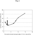
- Fig. 2 shows the relationship between the pore volume of pores having pore sizes of 10 nm or less on the carbon support for the electrode catalysts of the Examples and the Comparative Examples and H 2 diffusion resistance in MEAs having anodes for which the electrode catalysts were used.
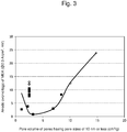
- Fig. 3 shows the relationship between the pore volume of pores having pore sizes of 10 nm or less on the carbon support for the electrode catalysts of the Examples and the Comparative Examples and anode overvoltage in MEAs having anodes for which the electrode catalysts were used.
- the pore volume of pores having pore sizes of 10 nm or less in a carbon support is large for the electrode catalysts of the Comparative Example 1 and 2. Therefore, catalyst particles having fine particle sizes, which are important for anode electrode catalyst activity, are highly likely to be supported inside a carbon support ( Fig. 1 ). This probably causes the H 2 diffusion pathway to be extended and H 2 diffusion resistance to increase, resulting in increased anode overvoltage ( Figs. 2 and 3 ). Meanwhile, the pore volume of pores having pore sizes of 10 nm or less in a carbon support is small for the electrode catalysts of Examples 1 to 12, and especially for Examples 3 to 12. Such carbon support has a solid structure with a small number of pores.
- catalyst particles having fine particle sizes which are important for anode electrode catalyst activity, are highly likely to be supported on the surface of a carbon support ( Fig. 1 ). This probably causes the H 2 diffusion pathway to be shortened and H 2 diffusion resistance to decrease, resulting in decreased anode overvoltage ( Figs. 2 and 3 ).
Landscapes
- Chemical & Material Sciences (AREA)
- Chemical Kinetics & Catalysis (AREA)
- Electrochemistry (AREA)
- General Chemical & Material Sciences (AREA)
- Engineering & Computer Science (AREA)
- Materials Engineering (AREA)
- Inert Electrodes (AREA)
- Catalysts (AREA)
- Fuel Cell (AREA)
Applications Claiming Priority (1)
| Application Number | Priority Date | Filing Date | Title |
|---|---|---|---|
| JP2015252162A JP6460975B2 (ja) | 2015-12-24 | 2015-12-24 | 燃料電池用電極触媒 |
Publications (1)
| Publication Number | Publication Date |
|---|---|
| EP3185342A1 true EP3185342A1 (en) | 2017-06-28 |
Family
ID=57609758
Family Applications (1)
| Application Number | Title | Priority Date | Filing Date |
|---|---|---|---|
| EP16206628.6A Pending EP3185342A1 (en) | 2015-12-24 | 2016-12-23 | Electrode catalyst for fuel cells |
Country Status (4)
| Country | Link |
|---|---|
| US (1) | US20170187047A1 (zh) |
| EP (1) | EP3185342A1 (zh) |
| JP (1) | JP6460975B2 (zh) |
| CN (1) | CN106920970B (zh) |
Families Citing this family (4)
| Publication number | Priority date | Publication date | Assignee | Title |
|---|---|---|---|---|
| JP6927870B2 (ja) | 2016-12-09 | 2021-09-01 | トヨタ自動車株式会社 | 燃料電池用電極触媒 |
| CN114902453A (zh) * | 2019-12-24 | 2022-08-12 | Agc株式会社 | 催化剂层、固体高分子型燃料电池用膜电极接合体、及固体高分子型燃料电池 |
| JP7175945B2 (ja) * | 2020-09-10 | 2022-11-21 | 日清紡ホールディングス株式会社 | 金属担持触媒、電池電極及び電池 |
| JP7175946B2 (ja) * | 2020-09-10 | 2022-11-21 | 日清紡ホールディングス株式会社 | 金属担持触媒、電池電極及び電池 |
Citations (7)
| Publication number | Priority date | Publication date | Assignee | Title |
|---|---|---|---|---|
| WO2003057367A2 (en) * | 2001-12-27 | 2003-07-17 | Aerogel Composite, Llc | Aerogel and metallic compositions |
| WO2006110822A2 (en) * | 2005-04-11 | 2006-10-19 | Aerogel Composite, Llc | Carbon aerogel supported metal catalyst and solid electrolyte composite |
| WO2007108497A1 (en) * | 2006-03-14 | 2007-09-27 | Cataler Corporation | Fuel cell electrode catalyst with improved noble metal utilization efficiency, method for manufacturing the same, and solid polymer fuel cell comprising the same |
| EP1953854A1 (en) * | 2005-11-14 | 2008-08-06 | Cataler Corporation | Fuel cell catalyst, fuel cell electrode and polymer electrolyte fuel cell provided with such fuel cell electrode |
| JP2012129059A (ja) | 2010-12-15 | 2012-07-05 | Cataler Corp | 燃料電池用担持触媒及び燃料電池 |
| WO2014175101A1 (ja) | 2013-04-25 | 2014-10-30 | 日産自動車株式会社 | 触媒の製造方法ならびに当該触媒を用いる電極触媒層、膜電極接合体および燃料電池 |
| JP2015071784A (ja) | 2008-02-19 | 2015-04-16 | キャボット コーポレイションCabot Corporation | メソポーラスカーボンブラック及びその製造方法 |
Family Cites Families (4)
| Publication number | Priority date | Publication date | Assignee | Title |
|---|---|---|---|---|
| US3501387A (en) * | 1967-07-11 | 1970-03-17 | Nat Lead Co | Continuous process for the electrolytic production of aluminum |
| JP2008041498A (ja) * | 2006-08-08 | 2008-02-21 | Sharp Corp | 固体高分子形燃料電池用触媒担持体の製造方法および固体高分子形燃料電池 |
| WO2011112992A1 (en) * | 2010-03-12 | 2011-09-15 | Energ2, Inc. | Mesoporous carbon materials comprising bifunctional catalysts |
| US20160064744A1 (en) * | 2013-04-25 | 2016-03-03 | Nissan Motor Co., Ltd. | Catalyst and electrode catalyst layer for fuel cell having the catalyst |
-
2015
- 2015-12-24 JP JP2015252162A patent/JP6460975B2/ja active Active
-
2016
- 2016-10-27 CN CN201610968794.XA patent/CN106920970B/zh active Active
- 2016-12-20 US US15/384,551 patent/US20170187047A1/en not_active Abandoned
- 2016-12-23 EP EP16206628.6A patent/EP3185342A1/en active Pending
Patent Citations (7)
| Publication number | Priority date | Publication date | Assignee | Title |
|---|---|---|---|---|
| WO2003057367A2 (en) * | 2001-12-27 | 2003-07-17 | Aerogel Composite, Llc | Aerogel and metallic compositions |
| WO2006110822A2 (en) * | 2005-04-11 | 2006-10-19 | Aerogel Composite, Llc | Carbon aerogel supported metal catalyst and solid electrolyte composite |
| EP1953854A1 (en) * | 2005-11-14 | 2008-08-06 | Cataler Corporation | Fuel cell catalyst, fuel cell electrode and polymer electrolyte fuel cell provided with such fuel cell electrode |
| WO2007108497A1 (en) * | 2006-03-14 | 2007-09-27 | Cataler Corporation | Fuel cell electrode catalyst with improved noble metal utilization efficiency, method for manufacturing the same, and solid polymer fuel cell comprising the same |
| JP2015071784A (ja) | 2008-02-19 | 2015-04-16 | キャボット コーポレイションCabot Corporation | メソポーラスカーボンブラック及びその製造方法 |
| JP2012129059A (ja) | 2010-12-15 | 2012-07-05 | Cataler Corp | 燃料電池用担持触媒及び燃料電池 |
| WO2014175101A1 (ja) | 2013-04-25 | 2014-10-30 | 日産自動車株式会社 | 触媒の製造方法ならびに当該触媒を用いる電極触媒層、膜電極接合体および燃料電池 |
Non-Patent Citations (1)
| Title |
|---|
| J. AM. CHEM. SOC., vol. 73, 1951, pages 373 - 380 |
Also Published As
| Publication number | Publication date |
|---|---|
| CN106920970A (zh) | 2017-07-04 |
| CN106920970B (zh) | 2020-04-03 |
| US20170187047A1 (en) | 2017-06-29 |
| JP2017117665A (ja) | 2017-06-29 |
| JP6460975B2 (ja) | 2019-01-30 |
Similar Documents
| Publication | Publication Date | Title |
|---|---|---|
| US10403906B2 (en) | Fuel cell electrode catalyst, method of producing the same, and fuel cell | |
| Liang et al. | Preparation and characterization of carbon-supported PtRuIr catalyst with excellent CO-tolerant performance for proton-exchange membrane fuel cells | |
| EP3552261B1 (en) | Electrode catalyst for fuel cell, method of producing the same, and fuel cell | |
| KR100868756B1 (ko) | 백금/루테늄 합금 담지 촉매, 그 제조방법 및 이를 이용한연료전지 | |
| US20170200956A1 (en) | Electrode catalyst for fuel cell and method of producing electrode catalyst for fuel cell | |
| EP3211696A1 (en) | Fuel cell electrode catalyst and manufacturing method thereof | |
| EP2634850B1 (en) | Composite, catalyst including the same, fuel cell and lithium air battery including the same | |
| US20180151888A1 (en) | Fuel-cell electrode catalyst, and production method therefor | |
| EP3185342A1 (en) | Electrode catalyst for fuel cells | |
| EP2575202A2 (en) | Electrode catalyst for fuel cell and method of preparation, membrane electrode assembly (mea) including the catalyst, and fuel cell including the mea | |
| EP3855543A1 (en) | Anode catalyst layer for fuel cell and fuel cell using same | |
| KR20140070246A (ko) | 연료전지용 전극 촉매, 그 제조방법, 이를 포함한 연료전지용 전극 및 연료전지 | |
| EP3855542A1 (en) | Anode catalyst layer for fuel cell and fuel cell using same | |
| WO2018104775A2 (en) | Electrode catalyst for fuel cell, method of producing the same, and fuel cell | |
| EP3855544A1 (en) | Anode catalyst layer for fuel cell and fuel cell using same | |
| US9147886B2 (en) | Electrode catalyst for fuel cell, method of preparing the same, membrane electrode assembly, and fuel cell including the same | |
| EP3855545A1 (en) | Anode catalyst layer for fuel cell and fuel cell using same | |
| JP2023115809A (ja) | 燃料電池用電極触媒 | |
| Huang et al. | A Pt/C Catalysts Using Chelating Agent Assisted Microwave Synthesis and Its Preparation | |
| JP5235280B2 (ja) | 固体高分子型燃料電池用アノード触媒 |
Legal Events
| Date | Code | Title | Description |
|---|---|---|---|
| PUAI | Public reference made under article 153(3) epc to a published international application that has entered the european phase |
Free format text: ORIGINAL CODE: 0009012 |
|
| STAA | Information on the status of an ep patent application or granted ep patent |
Free format text: STATUS: REQUEST FOR EXAMINATION WAS MADE |
|
| 17P | Request for examination filed |
Effective date: 20170123 |
|
| AK | Designated contracting states |
Kind code of ref document: A1 Designated state(s): AL AT BE BG CH CY CZ DE DK EE ES FI FR GB GR HR HU IE IS IT LI LT LU LV MC MK MT NL NO PL PT RO RS SE SI SK SM TR |
|
| AX | Request for extension of the european patent |
Extension state: BA ME |
|
| STAA | Information on the status of an ep patent application or granted ep patent |
Free format text: STATUS: EXAMINATION IS IN PROGRESS |
|
| 17Q | First examination report despatched |
Effective date: 20200624 |
|
| STAA | Information on the status of an ep patent application or granted ep patent |
Free format text: STATUS: EXAMINATION IS IN PROGRESS |