EP3185318A1 - Light-emitting device and power supply connector for light-emitting device - Google Patents
Light-emitting device and power supply connector for light-emitting device Download PDFInfo
- Publication number
- EP3185318A1 EP3185318A1 EP16205475.3A EP16205475A EP3185318A1 EP 3185318 A1 EP3185318 A1 EP 3185318A1 EP 16205475 A EP16205475 A EP 16205475A EP 3185318 A1 EP3185318 A1 EP 3185318A1
- Authority
- EP
- European Patent Office
- Prior art keywords
- light
- power supply
- emitting device
- support
- supply connector
- Prior art date
- Legal status (The legal status is an assumption and is not a legal conclusion. Google has not performed a legal analysis and makes no representation as to the accuracy of the status listed.)
- Granted
Links
- 230000000994 depressogenic effect Effects 0.000 claims description 29
- 239000000463 material Substances 0.000 description 58
- 239000004065 semiconductor Substances 0.000 description 29
- 229920005989 resin Polymers 0.000 description 19
- 239000011347 resin Substances 0.000 description 19
- 238000004519 manufacturing process Methods 0.000 description 12
- 238000000034 method Methods 0.000 description 12
- 229910052751 metal Inorganic materials 0.000 description 10
- 239000002184 metal Substances 0.000 description 10
- -1 polyethylene terephthalate Polymers 0.000 description 10
- OAICVXFJPJFONN-UHFFFAOYSA-N Phosphorus Chemical compound [P] OAICVXFJPJFONN-UHFFFAOYSA-N 0.000 description 9
- 239000000758 substrate Substances 0.000 description 6
- VYPSYNLAJGMNEJ-UHFFFAOYSA-N Silicium dioxide Chemical compound O=[Si]=O VYPSYNLAJGMNEJ-UHFFFAOYSA-N 0.000 description 5
- 239000000853 adhesive Substances 0.000 description 5
- 230000001070 adhesive effect Effects 0.000 description 5
- 229910052782 aluminium Inorganic materials 0.000 description 5
- XAGFODPZIPBFFR-UHFFFAOYSA-N aluminium Chemical compound [Al] XAGFODPZIPBFFR-UHFFFAOYSA-N 0.000 description 5
- 238000006243 chemical reaction Methods 0.000 description 5
- 238000009826 distribution Methods 0.000 description 5
- 150000004767 nitrides Chemical class 0.000 description 4
- KXGFMDJXCMQABM-UHFFFAOYSA-N 2-methoxy-6-methylphenol Chemical compound [CH]OC1=CC=CC([CH])=C1O KXGFMDJXCMQABM-UHFFFAOYSA-N 0.000 description 3
- PNEYBMLMFCGWSK-UHFFFAOYSA-N aluminium oxide Inorganic materials [O-2].[O-2].[O-2].[Al+3].[Al+3] PNEYBMLMFCGWSK-UHFFFAOYSA-N 0.000 description 3
- 239000000919 ceramic Substances 0.000 description 3
- 239000003822 epoxy resin Substances 0.000 description 3
- 239000000203 mixture Substances 0.000 description 3
- 229920001568 phenolic resin Polymers 0.000 description 3
- 239000005011 phenolic resin Substances 0.000 description 3
- 229920000647 polyepoxide Polymers 0.000 description 3
- 238000003825 pressing Methods 0.000 description 3
- 229920002050 silicone resin Polymers 0.000 description 3
- 239000004925 Acrylic resin Substances 0.000 description 2
- 229920000178 Acrylic resin Polymers 0.000 description 2
- 229910052684 Cerium Inorganic materials 0.000 description 2
- RYGMFSIKBFXOCR-UHFFFAOYSA-N Copper Chemical compound [Cu] RYGMFSIKBFXOCR-UHFFFAOYSA-N 0.000 description 2
- 229910052693 Europium Inorganic materials 0.000 description 2
- CPLXHLVBOLITMK-UHFFFAOYSA-N Magnesium oxide Chemical compound [Mg]=O CPLXHLVBOLITMK-UHFFFAOYSA-N 0.000 description 2
- 239000004954 Polyphthalamide Substances 0.000 description 2
- 229910052581 Si3N4 Inorganic materials 0.000 description 2
- GWEVSGVZZGPLCZ-UHFFFAOYSA-N Titan oxide Chemical compound O=[Ti]=O GWEVSGVZZGPLCZ-UHFFFAOYSA-N 0.000 description 2
- XLOMVQKBTHCTTD-UHFFFAOYSA-N Zinc monoxide Chemical compound [Zn]=O XLOMVQKBTHCTTD-UHFFFAOYSA-N 0.000 description 2
- MCMNRKCIXSYSNV-UHFFFAOYSA-N Zirconium dioxide Chemical compound O=[Zr]=O MCMNRKCIXSYSNV-UHFFFAOYSA-N 0.000 description 2
- 238000000231 atomic layer deposition Methods 0.000 description 2
- 229910052681 coesite Inorganic materials 0.000 description 2
- 239000003086 colorant Substances 0.000 description 2
- 229910052802 copper Inorganic materials 0.000 description 2
- 239000010949 copper Substances 0.000 description 2
- PMHQVHHXPFUNSP-UHFFFAOYSA-M copper(1+);methylsulfanylmethane;bromide Chemical compound Br[Cu].CSC PMHQVHHXPFUNSP-UHFFFAOYSA-M 0.000 description 2
- 229910052906 cristobalite Inorganic materials 0.000 description 2
- ZKATWMILCYLAPD-UHFFFAOYSA-N niobium pentoxide Chemical compound O=[Nb](=O)O[Nb](=O)=O ZKATWMILCYLAPD-UHFFFAOYSA-N 0.000 description 2
- TWNQGVIAIRXVLR-UHFFFAOYSA-N oxo(oxoalumanyloxy)alumane Chemical compound O=[Al]O[Al]=O TWNQGVIAIRXVLR-UHFFFAOYSA-N 0.000 description 2
- 239000002245 particle Substances 0.000 description 2
- BASFCYQUMIYNBI-UHFFFAOYSA-N platinum Chemical compound [Pt] BASFCYQUMIYNBI-UHFFFAOYSA-N 0.000 description 2
- 229920005668 polycarbonate resin Polymers 0.000 description 2
- 239000004431 polycarbonate resin Substances 0.000 description 2
- 229920000139 polyethylene terephthalate Polymers 0.000 description 2
- 239000005020 polyethylene terephthalate Substances 0.000 description 2
- 229920001721 polyimide Polymers 0.000 description 2
- 239000009719 polyimide resin Substances 0.000 description 2
- 229920006375 polyphtalamide Polymers 0.000 description 2
- 230000000630 rising effect Effects 0.000 description 2
- 238000007493 shaping process Methods 0.000 description 2
- 239000000377 silicon dioxide Substances 0.000 description 2
- HQVNEWCFYHHQES-UHFFFAOYSA-N silicon nitride Chemical compound N12[Si]34N5[Si]62N3[Si]51N64 HQVNEWCFYHHQES-UHFFFAOYSA-N 0.000 description 2
- 229910052814 silicon oxide Inorganic materials 0.000 description 2
- 238000003892 spreading Methods 0.000 description 2
- 238000004544 sputter deposition Methods 0.000 description 2
- 229910052682 stishovite Inorganic materials 0.000 description 2
- 229910052905 tridymite Inorganic materials 0.000 description 2
- DHKHKXVYLBGOIT-UHFFFAOYSA-N 1,1-Diethoxyethane Chemical compound CCOC(C)OCC DHKHKXVYLBGOIT-UHFFFAOYSA-N 0.000 description 1
- JMMZCWZIJXAGKW-UHFFFAOYSA-N 2-methylpent-2-ene Chemical compound CCC=C(C)C JMMZCWZIJXAGKW-UHFFFAOYSA-N 0.000 description 1
- 229910017109 AlON Inorganic materials 0.000 description 1
- 229910011255 B2O3 Inorganic materials 0.000 description 1
- VYZAMTAEIAYCRO-UHFFFAOYSA-N Chromium Chemical compound [Cr] VYZAMTAEIAYCRO-UHFFFAOYSA-N 0.000 description 1
- 229910001200 Ferrotitanium Inorganic materials 0.000 description 1
- KRHYYFGTRYWZRS-UHFFFAOYSA-M Fluoride anion Chemical compound [F-] KRHYYFGTRYWZRS-UHFFFAOYSA-M 0.000 description 1
- 229910004140 HfO Inorganic materials 0.000 description 1
- 229910020440 K2SiF6 Inorganic materials 0.000 description 1
- KKCBUQHMOMHUOY-UHFFFAOYSA-N Na2O Inorganic materials [O-2].[Na+].[Na+] KKCBUQHMOMHUOY-UHFFFAOYSA-N 0.000 description 1
- 239000004695 Polyether sulfone Substances 0.000 description 1
- 239000004743 Polypropylene Substances 0.000 description 1
- BQCADISMDOOEFD-UHFFFAOYSA-N Silver Chemical compound [Ag] BQCADISMDOOEFD-UHFFFAOYSA-N 0.000 description 1
- UCKMPCXJQFINFW-UHFFFAOYSA-N Sulphide Chemical compound [S-2] UCKMPCXJQFINFW-UHFFFAOYSA-N 0.000 description 1
- 229910004160 TaO2 Inorganic materials 0.000 description 1
- RTAQQCXQSZGOHL-UHFFFAOYSA-N Titanium Chemical compound [Ti] RTAQQCXQSZGOHL-UHFFFAOYSA-N 0.000 description 1
- 239000011354 acetal resin Substances 0.000 description 1
- 229910045601 alloy Inorganic materials 0.000 description 1
- 239000000956 alloy Substances 0.000 description 1
- 229910021502 aluminium hydroxide Inorganic materials 0.000 description 1
- WNROFYMDJYEPJX-UHFFFAOYSA-K aluminium hydroxide Chemical compound [OH-].[OH-].[OH-].[Al+3] WNROFYMDJYEPJX-UHFFFAOYSA-K 0.000 description 1
- JNDMLEXHDPKVFC-UHFFFAOYSA-N aluminum;oxygen(2-);yttrium(3+) Chemical compound [O-2].[O-2].[O-2].[Al+3].[Y+3] JNDMLEXHDPKVFC-UHFFFAOYSA-N 0.000 description 1
- 230000015572 biosynthetic process Effects 0.000 description 1
- UHYPYGJEEGLRJD-UHFFFAOYSA-N cadmium(2+);selenium(2-) Chemical compound [Se-2].[Cd+2] UHYPYGJEEGLRJD-UHFFFAOYSA-N 0.000 description 1
- 239000000404 calcium aluminium silicate Substances 0.000 description 1
- 235000012215 calcium aluminium silicate Nutrition 0.000 description 1
- WNCYAPRTYDMSFP-UHFFFAOYSA-N calcium aluminosilicate Chemical compound [Al+3].[Al+3].[Ca+2].[O-][Si]([O-])=O.[O-][Si]([O-])=O.[O-][Si]([O-])=O.[O-][Si]([O-])=O WNCYAPRTYDMSFP-UHFFFAOYSA-N 0.000 description 1
- 229940078583 calcium aluminosilicate Drugs 0.000 description 1
- ODINCKMPIJJUCX-UHFFFAOYSA-N calcium oxide Inorganic materials [Ca]=O ODINCKMPIJJUCX-UHFFFAOYSA-N 0.000 description 1
- 229910052804 chromium Inorganic materials 0.000 description 1
- 239000011651 chromium Substances 0.000 description 1
- 238000000748 compression moulding Methods 0.000 description 1
- 229910052593 corundum Inorganic materials 0.000 description 1
- 239000013078 crystal Substances 0.000 description 1
- XLJMAIOERFSOGZ-UHFFFAOYSA-M cyanate Chemical compound [O-]C#N XLJMAIOERFSOGZ-UHFFFAOYSA-M 0.000 description 1
- NQKXFODBPINZFK-UHFFFAOYSA-N dioxotantalum Chemical compound O=[Ta]=O NQKXFODBPINZFK-UHFFFAOYSA-N 0.000 description 1
- 230000000694 effects Effects 0.000 description 1
- 238000005265 energy consumption Methods 0.000 description 1
- 238000005516 engineering process Methods 0.000 description 1
- OGPBJKLSAFTDLK-UHFFFAOYSA-N europium atom Chemical compound [Eu] OGPBJKLSAFTDLK-UHFFFAOYSA-N 0.000 description 1
- 239000002223 garnet Substances 0.000 description 1
- 229910001679 gibbsite Inorganic materials 0.000 description 1
- 239000011521 glass Substances 0.000 description 1
- PCHJSUWPFVWCPO-UHFFFAOYSA-N gold Chemical compound [Au] PCHJSUWPFVWCPO-UHFFFAOYSA-N 0.000 description 1
- 229910052737 gold Inorganic materials 0.000 description 1
- 239000010931 gold Substances 0.000 description 1
- PJXISJQVUVHSOJ-UHFFFAOYSA-N indium(III) oxide Inorganic materials [O-2].[O-2].[O-2].[In+3].[In+3] PJXISJQVUVHSOJ-UHFFFAOYSA-N 0.000 description 1
- 238000001746 injection moulding Methods 0.000 description 1
- 229910010272 inorganic material Inorganic materials 0.000 description 1
- 239000011147 inorganic material Substances 0.000 description 1
- 229910052909 inorganic silicate Inorganic materials 0.000 description 1
- 238000009413 insulation Methods 0.000 description 1
- 239000012212 insulator Substances 0.000 description 1
- 239000001095 magnesium carbonate Substances 0.000 description 1
- 229910000021 magnesium carbonate Inorganic materials 0.000 description 1
- ZLNQQNXFFQJAID-UHFFFAOYSA-L magnesium carbonate Chemical compound [Mg+2].[O-]C([O-])=O ZLNQQNXFFQJAID-UHFFFAOYSA-L 0.000 description 1
- VTHJTEIRLNZDEV-UHFFFAOYSA-L magnesium dihydroxide Chemical compound [OH-].[OH-].[Mg+2] VTHJTEIRLNZDEV-UHFFFAOYSA-L 0.000 description 1
- 229910001635 magnesium fluoride Inorganic materials 0.000 description 1
- 239000000347 magnesium hydroxide Substances 0.000 description 1
- 229910001862 magnesium hydroxide Inorganic materials 0.000 description 1
- 238000012986 modification Methods 0.000 description 1
- 230000004048 modification Effects 0.000 description 1
- 239000002159 nanocrystal Substances 0.000 description 1
- 239000002105 nanoparticle Substances 0.000 description 1
- QJGQUHMNIGDVPM-UHFFFAOYSA-N nitrogen group Chemical group [N] QJGQUHMNIGDVPM-UHFFFAOYSA-N 0.000 description 1
- 239000012766 organic filler Substances 0.000 description 1
- 229910052697 platinum Inorganic materials 0.000 description 1
- 229920003229 poly(methyl methacrylate) Polymers 0.000 description 1
- 229920000636 poly(norbornene) polymer Polymers 0.000 description 1
- 229920001230 polyarylate Polymers 0.000 description 1
- 229920001225 polyester resin Polymers 0.000 description 1
- 239000004645 polyester resin Substances 0.000 description 1
- 229920006393 polyether sulfone Polymers 0.000 description 1
- 239000004926 polymethyl methacrylate Substances 0.000 description 1
- 229920006324 polyoxymethylene Polymers 0.000 description 1
- 229920001155 polypropylene Polymers 0.000 description 1
- 229920005990 polystyrene resin Polymers 0.000 description 1
- 229920001343 polytetrafluoroethylene Polymers 0.000 description 1
- 239000004810 polytetrafluoroethylene Substances 0.000 description 1
- 230000001681 protective effect Effects 0.000 description 1
- 239000002096 quantum dot Substances 0.000 description 1
- 229910052709 silver Inorganic materials 0.000 description 1
- 239000004332 silver Substances 0.000 description 1
- 229910000679 solder Inorganic materials 0.000 description 1
- 239000010935 stainless steel Substances 0.000 description 1
- 229910001220 stainless steel Inorganic materials 0.000 description 1
- IATRAKWUXMZMIY-UHFFFAOYSA-N strontium oxide Inorganic materials [O-2].[Sr+2] IATRAKWUXMZMIY-UHFFFAOYSA-N 0.000 description 1
- 239000000126 substance Substances 0.000 description 1
- 229920002803 thermoplastic polyurethane Polymers 0.000 description 1
- 229920005992 thermoplastic resin Polymers 0.000 description 1
- 229920001187 thermosetting polymer Polymers 0.000 description 1
- 239000010936 titanium Substances 0.000 description 1
- 238000001721 transfer moulding Methods 0.000 description 1
- 229920002554 vinyl polymer Polymers 0.000 description 1
- 238000003466 welding Methods 0.000 description 1
- 229910001845 yogo sapphire Inorganic materials 0.000 description 1
- 229910019901 yttrium aluminum garnet Inorganic materials 0.000 description 1
- RUDFQVOCFDJEEF-UHFFFAOYSA-N yttrium(III) oxide Inorganic materials [O-2].[O-2].[O-2].[Y+3].[Y+3] RUDFQVOCFDJEEF-UHFFFAOYSA-N 0.000 description 1
Images


Classifications
-
- H—ELECTRICITY
- H01—ELECTRIC ELEMENTS
- H01L—SEMICONDUCTOR DEVICES NOT COVERED BY CLASS H10
- H01L33/00—Semiconductor devices with at least one potential-jump barrier or surface barrier specially adapted for light emission; Processes or apparatus specially adapted for the manufacture or treatment thereof or of parts thereof; Details thereof
- H01L33/48—Semiconductor devices with at least one potential-jump barrier or surface barrier specially adapted for light emission; Processes or apparatus specially adapted for the manufacture or treatment thereof or of parts thereof; Details thereof characterised by the semiconductor body packages
- H01L33/62—Arrangements for conducting electric current to or from the semiconductor body, e.g. lead-frames, wire-bonds or solder balls
-
- H—ELECTRICITY
- H01—ELECTRIC ELEMENTS
- H01L—SEMICONDUCTOR DEVICES NOT COVERED BY CLASS H10
- H01L33/00—Semiconductor devices with at least one potential-jump barrier or surface barrier specially adapted for light emission; Processes or apparatus specially adapted for the manufacture or treatment thereof or of parts thereof; Details thereof
- H01L33/48—Semiconductor devices with at least one potential-jump barrier or surface barrier specially adapted for light emission; Processes or apparatus specially adapted for the manufacture or treatment thereof or of parts thereof; Details thereof characterised by the semiconductor body packages
- H01L33/483—Containers
- H01L33/486—Containers adapted for surface mounting
-
- H—ELECTRICITY
- H01—ELECTRIC ELEMENTS
- H01R—ELECTRICALLY-CONDUCTIVE CONNECTIONS; STRUCTURAL ASSOCIATIONS OF A PLURALITY OF MUTUALLY-INSULATED ELECTRICAL CONNECTING ELEMENTS; COUPLING DEVICES; CURRENT COLLECTORS
- H01R24/00—Two-part coupling devices, or either of their cooperating parts, characterised by their overall structure
- H01R24/66—Two-part coupling devices, or either of their cooperating parts, characterised by their overall structure with pins, blades or analogous contacts and secured to apparatus or structure, e.g. to a wall
-
- H—ELECTRICITY
- H01—ELECTRIC ELEMENTS
- H01L—SEMICONDUCTOR DEVICES NOT COVERED BY CLASS H10
- H01L2224/00—Indexing scheme for arrangements for connecting or disconnecting semiconductor or solid-state bodies and methods related thereto as covered by H01L24/00
- H01L2224/01—Means for bonding being attached to, or being formed on, the surface to be connected, e.g. chip-to-package, die-attach, "first-level" interconnects; Manufacturing methods related thereto
- H01L2224/42—Wire connectors; Manufacturing methods related thereto
- H01L2224/47—Structure, shape, material or disposition of the wire connectors after the connecting process
- H01L2224/48—Structure, shape, material or disposition of the wire connectors after the connecting process of an individual wire connector
- H01L2224/4805—Shape
- H01L2224/4809—Loop shape
- H01L2224/48091—Arched
-
- H—ELECTRICITY
- H01—ELECTRIC ELEMENTS
- H01L—SEMICONDUCTOR DEVICES NOT COVERED BY CLASS H10
- H01L2224/00—Indexing scheme for arrangements for connecting or disconnecting semiconductor or solid-state bodies and methods related thereto as covered by H01L24/00
- H01L2224/01—Means for bonding being attached to, or being formed on, the surface to be connected, e.g. chip-to-package, die-attach, "first-level" interconnects; Manufacturing methods related thereto
- H01L2224/42—Wire connectors; Manufacturing methods related thereto
- H01L2224/47—Structure, shape, material or disposition of the wire connectors after the connecting process
- H01L2224/48—Structure, shape, material or disposition of the wire connectors after the connecting process of an individual wire connector
- H01L2224/481—Disposition
- H01L2224/48135—Connecting between different semiconductor or solid-state bodies, i.e. chip-to-chip
- H01L2224/48137—Connecting between different semiconductor or solid-state bodies, i.e. chip-to-chip the bodies being arranged next to each other, e.g. on a common substrate
-
- H—ELECTRICITY
- H01—ELECTRIC ELEMENTS
- H01R—ELECTRICALLY-CONDUCTIVE CONNECTIONS; STRUCTURAL ASSOCIATIONS OF A PLURALITY OF MUTUALLY-INSULATED ELECTRICAL CONNECTING ELEMENTS; COUPLING DEVICES; CURRENT COLLECTORS
- H01R2103/00—Two poles
Definitions
- the present disclosure relates to a light-emitting device and a power supply connector for a light-emitting device.
- semiconductor light-emitting elements have been used, replacing incandescent lamps and fluorescent lamps.
- a typical example of a semiconductor light-emitting element is a light emitting diode (i.e., LED).
- LED light emitting diode
- a lighting device using a semiconductor light-emitting element is typically configured to include: a light-emitting device having a light-emitting element mounted therein and having a connector; and a power supply including a power supply circuit for converting AC power into DC power and a terminal or a connector that can be connected to the connector of the light-emitting device.
- a light-emitting module including a heat spreader, a connector provided on the heat spreader, and a wiring board having an LED element mounted thereon.
- An example embodiment of the present application provides a light-emitting device that is made up of fewer parts and of which the manufacturing cost can be reduced.
- a light-emitting device of the present disclosure includes: a support having a primary surface; a power supply connector located on the primary surface of the support and including one or more wire pads; a light-emitting element located on the primary surface of the support; and one or more wires connecting the light-emitting element and the one or more wire pads; and a cover member located on the primary surface of the support and covering the light-emitting element and the wire pads.
- Certain embodiments of the present application provide a light-emitting device that is made up of fewer parts and of which the manufacturing cost can be reduced.
- Example embodiments of a light-emitting device will now be described in detail.
- the following embodiments are illustrative, and the present invention is not limited to the embodiments.
- similar descriptions may be omitted or elements not referred to in the description may not be assigned reference signs for ease of understanding or for avoiding unnecessary redundancy.
- FIG. 1A is a perspective view showing an example of a light-emitting device 101 of the present embodiment.
- the light-emitting device 101 includes a support 11, a power supply connector 21, a light-emitting element 31 and wires 41.
- the light-emitting device 101 preferably further includes a cover member 51 located on the support 11, covering the light-emitting element 31.
- cover member 51 located on the support 11, covering the light-emitting element 31.
- FIG. 1A and the subsequent figures only the outer shape of the cover member 51 is shown, and the inside structure covered by the cover member 51 is shown, for ease of understanding.
- the support 11 has a primary surface 11a , and supports thereon the power supply connector 21 and the light-emitting element 31.
- the support 11 preferably has a high thermal conductivity so that heat generated from the light-emitting element 31 is efficiently conducted and dissipated.
- the support 11 may or may not be insulative.
- a non-insulative, i.e., conductive, support 11 may be a plate-shaped member of a metal such as aluminum, copper, titanium or stainless steel.
- An insulative support 11 may be a plate-shaped member formed from an insulative material such as aluminum nitride, silicon nitride, aluminum oxide (alumina) or silicon oxide, for example.
- the support 11 may also be a plate-shaped member formed of a resin such as a phenolic resin, an epoxy resin, a polyimide resin, a BT resin, polyphthalamide (PPA) or polyethylene terephthalate (PET).
- a resin-made plate-shaped member When a resin-made plate-shaped member is used, a ceramic or metal mounting board may further be provided, which has a better thermal conductivity than a resin.
- the support 11 may be a plate-shaped member including primary surfaces, one or both of which may be conductive and have one or more insulating layers located thereon.
- a layer of an insulator or a resin described above may be provided on one primary surface or on each of primary surfaces of the conductive plate-shaped member described above.
- an aluminum layer is formed by sputtering on the surface of a conductive plate-shaped member and oxidized in the atmospheric air to provide a transparent alumina layer, or an inorganic material (specifically, aluminum oxide, silicon oxide, aluminum nitride or silicon nitride) may be formed by sputtering, an atomic layer deposition method (ALD), or the like.
- ALD atomic layer deposition method
- the primary surface 11a of the support 11 may be highly reflective.
- a metal layer having a high reflectance may be formed on the primary surface 11a of the support 11.
- a layer or a member having a high reflectance may be provided only in a portion of the primary surface 11a of the support 11 where the light-emitting element 31 is mounted.
- the support 11 may be a plate-shaped member formed of aluminum, and a plate-shaped member of aluminum having high-reflectance may be provided, by means of welding, or the like, in a region where the light-emitting element 31 is mounted.
- the thickness of the support 11 is about 0.1 mm or more and about 10 mm or less, for example. It suffices for the support 11 to have a sufficient mechanical strength to function as a support, depending on the material used in the support 11, i.e., a strength less likely to be deformed during the manufacture of the light-emitting device 101 or during the manufacture of a lighting device or other applications using the light-emitting device 101.
- the support 11 may have any size depending on its application.
- the support 11 has a circular shape having a diameter of about 1 cm or more and about 10 cm or less, or a rectangular shape of a similar size, for example.
- the support 11 formed of a plate-shaped metal member with an electrically insulating layer provided on the surface thereof.
- FIG. 1B is a schematic view showing a cross section of the power supply connector 21 supported on the support 11.
- the power supply connector 21 includes a body 22, wire pads 23a , and external terminals 23b and 24b.
- the power supply connector 21 is capable of engaging with pins or connectors through which power is supplied, and functions as an interconnect for transmitting power supplied from outside to the wire pads 23a .
- the body 22 has an upper surface 22a and a lower surface 22b, and the lower surface 22b is secured on the support 11.
- the body 22 is connected to the support 11 by placing an adhesive between the lower surface 22b and the primary surface 11a of the support 11.
- the body 22 has a first portion 22c and a second portion 22d.
- the first portion 22c includes the wire pads 23a
- the second portion 22d includes a portion to be engaged with external pins or connectors through which power is supplied.
- a set of wire pads 23a are provided on the upper surface 22a in the first portion 22c.
- Holes 22g are provided in the second portion 22d.
- two holes 22g are provided.
- the external terminals 23b and 24b are located inside each of the holes 22g.
- the external terminals 23b in the holes 22g are electrically connected to the wire pads 23a via a connecting portion 23c buried inside the body 22.
- the external terminals 24b is connected to a buried portion 24c buried inside the body 22.
- the wire pads 23a , the connecting portion 23c and the external terminals 23b may be an integrally-formed metal member, and the external terminals 24b and the buried portion 24c may be an integrally-formed metal member.
- the wire pads 23a and the external terminals 23b may be members independent of each other, which are electrically connected to each other by the conductive connecting portion 23c.
- the support 11 has holes 11g located so as to correspond to each holes 22g provided in the body 22 of the power supply connector 21.
- the sizes of the holes 22g of the power supply connector 21 may be equal to or different from the sizes of the holes 11g of the support 11.
- the holes 22g of the power supply connector 21 may be larger or smaller than the holes 11g of the support 11 as long as a set of pins, through which power is supplied from outside, are in contact at least with the external terminals 23b in the holes 22g of the power supply connector 21.
- the contact areas between the pins and the external terminals 23b are preferably large. It is therefore preferred that the external terminals 23b have certain lengths in the direction in which the holes 22g extends and that the height h2 of the second portion 22d of the body 22 is large.
- wire pads 23a which are located on the first portion 21 c of the power supply connector 21, are connected to ends of the wires 41.
- the wires 41 include rising portions which rise from the surfaces of the wire pads 23a and it is preferable that the rising portions of the wires 41 do not shade the light emitted from the light-emitting element.
- the wire pads 23a are positioned at lower heights from the primary surface 11a of the support 11 and that the height h1 of the first portion 22c of the power supply connector 21 is lower.
- the relationship h1 ⁇ h2 is satisfied.
- the light-emitting element 31 is preferably a semiconductor light-emitting element. It may be a known light-emitting element made from any of various semiconductor materials, such as a light-emitting diode (LED) or a laser diode (LD). A wavelength range of light emitted from the light-emitting element 31 may be appropriately selected.
- the light-emitting element 31 may include a semiconductor layer formed from a nitride-based semiconductor (In x AlyGa) 1-x-y N, 0 ⁇ X, 0 ⁇ Y, X + Y ⁇ 1). In order to emit red light, it may include a semiconductor layer formed from GaAlAs or AlInGaP.
- a light-emitting element formed from any other semiconductor material may also be used.
- the semiconductor used for the light-emitting element a composition, a color of light emission, a size and the number thereof may be appropriately selected depending on the purpose.
- Various light-emitting wavelengths may be selected depending on the material of the semiconductor layer and the degree of crystal mix thereof.
- the wavelength range of light emitted from the light-emitting element 31 is not limited to visible light, but may also be ultraviolet light and infrared light.
- FIG. 1C is a schematic cross-sectional view showing an example of the light-emitting element 31.
- the light-emitting element 31 includes a substrate 32 and a semiconductor layered structure 33 formed on the substrate 32.
- the semiconductor layered structure 33 includes an active layer 35, and an n-side semiconductor layer 34 and a p-side semiconductor layer 36 with the active layer 35 disposed therebetween.
- the light-emitting element 31 further includes an n electrode 37 and a p electrode 38 electrically connected to the n-side semiconductor layer 34 and the p-side semiconductor layer 36, respectively.
- the semiconductor layer structure 33 may include various other semiconductor layers, such as a buffer layer for improving the crystalline quality of the semiconductor layer to be layered thereon, a semiconductor layer for improving the efficiency of injecting electrons or holes into the active layer, and a semiconductor layer for reducing the contact resistance with the n electrode 37 or the p electrode 38.
- the light-emitting element 31 has a face-up structure, and emits light from the side on which the n electrode 37 and the p electrode 38 are provided.
- a reflective layer may be included between the active layer 35 and the substrate 32 or on the back surface of the substrate 32.
- the light-emitting element 31 may be resin-encapsulated or may be a bare chip.
- the light-emitting element 31 is preferably a bare chip in order to reduce the manufacturing cost.
- "bare chip” means the chip is not packaged.
- a protective film, such as an oxide film or a nitride film, may be formed on the surface of the chip.
- the light-emitting element 31 is located on the support 11 so that the back surface of the substrate 32 is in contact with the primary surface 11a of the support 11.
- the wires 41 electrically connect the n electrode 37 and the p electrode 38 of the light-emitting element 31 with the two wire pads 23a of the power supply connector 21. Specifically, one end of each wire 41 is electrically connected to the n electrode 37 or the p electrode 38, with the other end thereof connected to one of the two wire pads 23a .
- the wires 41 are made from a wire material of gold, silver, copper, platinum, aluminum, etc., or an alloy thereof, and are connected by using any wire bonding technique commonly used in the field of semiconductor manufacturing technology.
- the cover member 51 is located on the support 11 and covers the light-emitting element 31.
- the cover member 51 covers the light-emitting element 31, thereby protecting the light-emitting element 31 from the ambient environment. More preferably, the cover member 51 covers the wires 41 and the wire pads 23a . That is, the cover member 51 may cover a portion of the power supply connector 21 where the wire pads 23a are located, and expose the other portion of the power supply connector 21. This makes it possible to also protect the wires 41 and the wire pads 23a from the ambient environment and increases the reliability of the light-emitting device 101.
- the cover member 51 can also control the light distribution characteristics of light emitted from the light-emitting element 31. Also since the the external terminals 23b and 24b are not covered with the cover member 51, the power supply connector 21 can secure electricaly commenction to an outer circuit.
- the material of the cover member 51 may be a thermosetting resin such as a silicone resin, a silicone-modified resin, an epoxy resin and a phenolic resin, a thermoplastic resin such as a polycarbonate resin, an acrylic resin, a methylpentene resin and a polynorbornene resin, or a translucent material such as a glass.
- a silicone resin is preferably selected, among materials above, in view of its light resistance and ease of shaping.
- the cover member 51 may contain a wavelength conversion material such as a phosphor, a colorant, etc., for absorbing light emitted from the light-emitting element 31 to emit light of a different wavelength. In order to increase the uniformity of light emitted from the light-emitting element 31, the cover member 51 may further contain a light-diffusing material.
- the wavelength conversion material may be selected from materials capable of absorbing light emitted from the light-emitting element 31 and converting the wavelength thereof into light of a different wavelength.
- it may be a cerium-activated yttrium aluminum garnet (YAG)-based phosphor, a cerium-activated lutetium aluminum garnet (LAG), an europium and/or chromium-activated nitrogen-containing calcium aluminosilicate (CaO-Al 2 O 3 -SiO 2 )-based phosphor, an europium-activated silicate ((Sr,Ba) 2 SiO 4 )-based phosphor, a ⁇ -sialon phosphor, a nitride-based phosphor such as a CASN-based or SCASN-based phosphor, a KSF-based phosphor (K 2 SiF 6 :Mn), a sulfide-based phosphor, etc.
- the wavelength conversion material may be a light-emitting substance such as those called “nanocrystal” and "quantum dot", for example.
- a material may be a semiconductor material including, for example, a group II-VI, group III-V or group IV-VI semiconductor, specifically, nano-sized highly-dispersed particles such as CdSe, core-shell-type CdS x Se 1-x /ZnS and GaP.
- the light-diffusing material may be an oxide such as SiO 2 , Al 2 O 3 , Al(OH) 3 , MgCO 3 , TiO 2 , ZrO 2 , ZnO, Nb 2 O 5 , MgO, Mg(OH) 2 , SrO, In 2 O 3 , TaO 2 , HfO, SeO, Y 2 O 3 , CaO, Na 2 O or B 2 O 3 , a nitride such as SiN, AlN or AlON, and a fluoride such as MgF 2 . They may be used alone or as a mixture.
- a plurality of separately-formed layers each having a light-diffusing material dispersed in a resin as described above may be layered together.
- the light-diffusing material may be an organic filler.
- various resins having a particle shape may be used.
- the various resins may include, for example, a silicone resin, a polycarbonate resin, a polyether sulfone resin, a polyarylate resin, a polytetrafluoroethylene resin, an epoxy resin, a cyanate resin, a phenolic resin, an acrylic resin, a polyimide resin, a polystyrene resin, a polypropylene resin, a polyvinyl acetal resin, a polymethyl methacrylate resin, a urethane resin, a polyester resin, etc.
- the light-diffusing material is preferably a material that does not substantially convert the wavelength of light emitted from the light-emitting element 31.
- the content of the light-diffusing material can be appropriately determined within the range that light is diffused, and is, for example, in a range of about 0.01 wt% to about 30 wt%, and preferably in a range of about 2 wt% to about 20 wt%.
- the size of the light-diffusing material can also be appropriately determined within the range light is diffused, and is, for example, in a range of about 0.01 ⁇ m to about 30 ⁇ m, and preferably in a range of about 0.5 ⁇ m to about 10 ⁇ m.
- the shape may be a spherical shape or a scale shape, but is preferably a spherical shape so that light is diffused uniformly.
- the shape of the cover member 51 influences the light distribution characteristics for light emitted from the light-emitting device 101. As will be described below, one may adjust the viscosity of the material of the cover member 51, or press a cast of an intended shape onto the formed cover member 51, thereby shaping the cover member 51.
- the light-emitting device 101 can be manufactured by the following method, for example. First, the support 11, the power supply connector 21 and the light-emitting element 31 are provided. The support 11 includes the holes 11g therein.
- the light-emitting element 31 and the power supply connector 21 are attached to the support 11.
- Various adhesives may be used for the attachment.
- a heat-resistant adhesive is preferably used for the attachment because heat is generated as the light-emitting element 31 emits light.
- the power supply connector 21 is located on the primary surface 11a of the support 11 so that the holes 22g of the power supply connector 21 correspond to the holes 11g of the support 11.
- the light-emitting element 31 is located, in a face-up position, on the primary surface 11a of the support 11 so that the substrate 32 side thereof is attached to the support 11 and so that the n electrode 37 and the p electrode 38 of the light-emitting element 31 are facing up.
- the wires 41 may be formed by utilizing a wire bonding technique using heat, pressure, ultrasonic waves, etc., used in the manufacture of semiconductor devices as described above.
- a cover member material having a wavelength conversion material, a light-diffusing material, or the like, dispersed in an uncured resin material is prepared.
- the material is extruded so as to cover the light-emitting element 31, the wires 41 and the wire pads 23a , and the material is cured and molded by compression molding, injection molding, transfer molding, or the like.
- the viscosity of the material of the cover member 51 may be adjusted, and the material may be dripped or drawn in a pattern so as to cover the light-emitting element 31, the wires 41 and the wire pads 23a .
- the cover member 51 Since a curved surface is formed by the surface tension of the material itself depending on the adjusted viscosity, it is possible to form the cover member 51 by curing the material by using a curing condition such as heat or ultraviolet light. With this method, the cover member 51 can be formed on the support 11 more easily with no need for a die.
- the viscosity adjustment of the material of the cover member in this formation method can be done based on the shape and the amount of addition of the light-diffusing material, the wavelength conversion material and the colorant, as well as the viscosity of the resin as described above. Thus, the light-emitting device 101 is completed.
- the wire pads 23a are provided on the power supply connector 21, and the power supply connector 21 and the light-emitting element 31 can be directly electrically connected to each other, without using a mounting board for mounting the light-emitting element 31 thereon. It possible to electrically connect the power supply connector 21 and the light-emitting element 31 to each other by placing the power supply connector 21 and the light-emitting element 31 on the support 11 and connecting the power supply connector 21 and the light-emitting element 31 by the wires 41. This makes it possible to reduce the number of parts and reduce the manufacturing cost.
- the power supply connector 21 it is possible to provide pins or connectors on the power-supplying circuit, which can then be electrically connected to the light-emitting device 101 easily and reliably. Therefore, it is possible to simplify the assembly of a lighting device, or the like, incorporating the light-emitting device 101, and it is possible to shorten the tact time and to reduce the failure rate in the manufacture.
- the light-emitting element 31, the wires 41 and the wire pads 23a are covered by the cover member 51, thereby protecting the light-emitting element 31, and the wires between the light-emitting element 31 and the power supply connector. Therefore, it is possible to increase the reliability of the light-emitting device 101. Moreover, because a bare chip can be used as the light-emitting element 31, it is possible to further reduce the manufacturing cost as compared with cases where packaged light-emitting element is used.
- FIG. 2A and FIG. 2B are a perspective view and a cross-sectional view, respectively, showing an example of a light-emitting device 102 of the present embodiment.
- the light-emitting device 102 is different from the light-emitting device 101 of the first embodiment in that the light-emitting device 102 includes a power supply connector 121 whose shape is different from that of the power supply connector 21.
- FIG. 2C is a plan view showing the power supply connector 121.
- the power supply connector 121 includes a body 122 located on the primary surface 11a of the support 11, and the body 122 includes a wall portion 22h and a base portion 22i.
- the wall portion 22h has a ring shape defining a through hole therein. Therefore, when the power supply connector 121 is located on the primary surface 11a of the support 11, the wall portion 22h surrounds the light-emitting element 31 on the primary surface 11a .
- the space defined by the wall portion 22h has a circular shape, as seen from above (as seen from a direction vertical to the primary surface 11a ), but the inside space defined by the wall portion 22h may be an elliptical shape other than a circular shape, or may be a polygonal shape such as a triangular shape or a quadrangular shape.
- the base portion 22i includes the first portion 22c and the second portion 22d as described above in the first embodiment.
- the wall portion 22h is connected to the base portion 22i generally at the boundary between the first portion 22c and the second portion 22d.
- the first portion 22c is located inside the region surrounded by the wall portion 22h.
- the height of the base portion 22i is preferably equal to or lower than the height h3 of the wall portion 22h.
- the base portion 22i will not shade the light emitted from the light-emitting device 102, realizing uniform light distribution characteristics.
- the cover member 51 is located inside the region surrounded by the wall portion 22h.
- the wall portion 22h defines the region where the cover member 51 is located.
- the wall portion 22h prevents the material from excessively spreading on the primary surface 11a of the support 11 and limits the movement of the material so that the material remains inside an intended region. Therefore, when the material is cured to form the cover member 51, the shape and the size of the bottom surface of the cover member 51 in contact with the support 11 can be controlled by the wall portion 22h. More specifically, it is possible to control the surface shape and the size of the cover member 51 by adjusting the amount of the material, the viscosity thereof, and the size and the shape defined by the wall portion 22h.
- the light-emitting device 102 it is easier to form the cover member 51 having an intended shape even when the material of the cover member 51 is dripped or drawn in a pattern and the outer shape of the cover member 51 is controlled by the surface tension thereof. That is, it is possible to realize the cover member 51 having a good formability even with a simple process.
- FIG. 3A and FIG. 3B are a perspective view and a cross-sectional view, respectively, showing an example of a light-emitting device 103 of the present embodiment.
- the wall portion 22h defining the region where the cover member 51 is located is included in the power supply connector 121.
- a support 111 has a depressed portion 111r , and the depressed portion 111r defines the region where the cover member 51 is located.
- the depressed portion 111r is provided on a primary surface 111a of the support 111. As the support 111 is seen from above, the depressed portion 111r has a circular shape. The depressed portion 111r has a side surface 111s and a bottom surface 111t , and the bottom surface 111t is the region where the cover member 51 is located.
- a power supply connector 221 has a lower surface 221b, which has a step 221s.
- the step 221s has a height corresponding to the side surface 111s of the depressed portion 111r , and the power supply connector 221 is divided into a first portion 222c and a second portion 222d by the step 221s.
- the first portion 222c is in contact with the bottom surface 111t of the depressed portion 111r
- the second portion 222d is located on the primary surface 111a around the depressed portion 111r . That is, the first portion 222c is located inside the depressed portion 111r .
- the support 111 having the depressed portion 111r can be formed by pressing the primary surface 111a of the support 111 by a press-working process, or the like, to compress a portion of the support 111.
- a ceramic plate is provided, and a region thereof corresponding to the depressed portion 111r may be ground off, or green sheets with a hole therein corresponding to the depressed portion 111r maybe layer and sintered together.
- the cover member 51 is located inside the depressed portion 111r , and the depressed portion 111r defines the region where the cover member 51 is located.
- the uncured material of the cover member 51 is dripped or drawn in a pattern so as to cover the light-emitting element 31, the wires 41 and the wire pads 23a , the material is kept inside the depressed portion 111r . Therefore, when the material is cured to form the cover member 51, it is possible to control the shape and the size of the bottom surface of the cover member 51, which is the region to be in contact with the support 11. As in the second embodiment, it is possible to control the surface shape and the size of the cover member 51 by adjusting the amount of the material, the viscosity thereof, and the size and the shape of the bottom surface 111t of the depressed portion 111r .
- the light-emitting device 103 as in the second embodiment, it is easier to form the cover member 51 having an intended shape even when the material of the cover member 51 is dripped or drawn in a pattern and the outer shape of the cover member 51 is controlled by the surface tension thereof. That is, it is possible to realize the cover member 51 having a good formability even with a simple process.
- the configuration provided in the support 11 for defining the region where the cover member 51 is located can be a depressed portion and can be other configurations as well. For example, it may be a ridge portion protruding from the primary surface of the support.
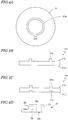
- FIG. 4A and FIG. 4B are a top view and a cross-sectional view, respectively, showing a support 211 having a ridge portion 211e .
- the ridge portion 211e of the support 211 has a ring shape and protrudes from a primary surface 211a .
- the ridge portion 211e is absent in a region 211f , thereby breaking the ring in the region 211f .
- the power supply connector 21 of the first embodiment can be located in the region 211f .
- the provision of the region 211f allows the power supply connector 21 to be located on the primary surface 211a of the support 211 even when the lower surface 22b of the power supply connector 21 is flat.
- a back surface 211b of the support 211 having the ridge portion 211e may be flat as shown in FIG. 4B , or may have a ring-shaped depressed portion 211g located so as to correspond to the ridge portion 211e of the primary surface 211a as shown in FIG. 4C .
- the support 211 having such a shape as shown in FIG. 4B can be formed by, for example, providing a flat metal plate, and removing a region thereof excluding the ridge portion 211e by grinding, etc.
- 4C may be formed by providing a pair of dies having a protruding portion and a depressed portion corresponding to the ridge portion 211e, and pressing a metal plate by the pair of dies disposing the metal plate therebetween using a press working process.
- the ridge portion 211e is absent in the region where the power supply connector is located.
- the support may have a ring-shaped ridge portion 211e with no region 211f where the ring is broken.
- a power supply connector 21' may be provided with the lower surface 22b having a groove 22j for straddling the ridge portion 211e, as shown in FIG. 4D , and the power supply connector 21' may be located on the primary surface of the support so that the groove 22j engages with the ridge portion 211e .
- the groove 22j is preferably located in the vicinity of the boundary between the first portion 22c and the second portion 22d. Then, when a light-emitting device is produced by using the power supply connector 21' , the first portion 22c can be located inside the region surrounded by the ring-shaped ridge portion 211e.
- FIG. 5 is a top view showing an example of a light-emitting device 104 of the present embodiment.
- the light-emitting device 104 of the fourth embodiment is different from the light-emitting device 102 of the second embodiment in that it includes a plurality of light-emitting elements 31.
- the light-emitting device 104 includes a plurality of light-emitting elements 31 located inside the region surrounded by the wall portion 22h on the primary surface 11a of the support 11. While FIG. 5 shows sixteen light-emitting elements 31, the number of light-emitting elements 31 is not limited thereto, and it may be any number of two or more. Each of the light-emitting elements 31 is electrically connected to the two wire pads 23a .
- FIG. 5 shows sixteen light-emitting elements 31, the number of light-emitting elements 31 is not limited thereto, and it may be any number of two or more.
- Each of the light-emitting elements 31 is electrically connected to the two wire pads 23a .
- FIG. 5 shows an example in which sixteen light-emitting elements 31 are connected together in series by wires 42, and those light-emitting elements 31 at the opposite ends are connected to the wire pads 23a by the wires 41.
- the light-emitting elements 31 may all be connected together in a parallel connection, or groups of a predetermined number of serially-connected elements may be connected together in a parallel connection.
- the light-emitting device 104 includes a plurality of light-emitting elements 31, all of the light-emitting elements 31 are located in the region surrounded by the wall portion 22h of the power supply connector 121.
- the wall portion 22h defines the region where the cover member 51 is located, and the cover member 51 is located inside the region surrounded by the wall portion 22h. Therefore, the cover member 51 inside the wall portion 22h covers all of the light-emitting elements 31.
- the cover member 51 is shaded in FIG. 5 for ease of understanding. Also in the subsequent figures, the cover member 51 shown in a top view is shaded.
- the wires 42 connecting between the light-emitting elements 31, the wires 41 connecting between the light-emitting elements 31 and the wire pads 23a , and the wire pads 23a are covered by the cover member 51, thereby protecting the light-emitting elements 31 and the wires connecting between the light-emitting elements 31 and the power supply connector. Therefore, it is possible to realize the light-emitting device 104 having a high luminance and a high reliability.
- FIG. 6 is a top view showing an example of a light-emitting device 105 of the present embodiment.
- the light-emitting devices of the preceding embodiments each include a power supply connector having wire pads on the upper surface.
- the light-emitting device 105 of the present embodiment includes a power supply connector including electrodes that can be surface-mounted.
- the light-emitting device 105 includes a support 311, a power supply connector 121', a plurality of light-emitting elements 31', and the cover member 51.
- the support 311 has conductive patterns 312a to 312h on a primary surface 311a .
- the power supply connector 121' includes the wall portion 22h, and two holes 22g located in the second portion 22d of the base portion.
- the external terminals 23b and 24b are located in each hole 22g.
- the power supply connector 121' includes electrodes 23f and 24f provided on the lower surface, and the electrodes 23f and 24f are electrically connected to the external terminals 23b and 24b, respectively, located in the hole 22g.
- the electrodes 23f and 24f connected to the external terminals 23b and 24b of one hole 22g are electrically connected to a conductive pattern 312a .
- the electrodes 23f and 24f connected to the external terminals 23b and 24b of the other hole 22g are electrically connected to a conductive pattern 312h.
- Each of the light-emitting element 31' includes a pair of electrodes that can be surface-mounted or flip chip bonded, and two of the conductive patterns 312a to 312h are electrically connected to the pair of electrodes.
- Each of the light-emitting elements 31' may be a resin-encapsulated light-emitting element or may be a bare chip.
- the electrodes 23f and 24f located on the lower surface of the power supply connector 121' and the electrodes of the light-emitting elements 31' are electrically connected to the conductive patterns 312a to 312h by using flip chip bonding, conductive adhesive, solder reflow, etc.
- the wall portion 22h has a ring shape, surrounding the light-emitting elements 31' on the primary surface 311a of the support 311.
- the cover member 51 is located inside the region surrounded by the wall portion 22h on the primary surface 311a of the support 311.
- the light-emitting device 105 includes the electrodes 23f and 24f provided on the lower surface of the power supply connector 121', and the power supply connector 121' can be surface-mounted. Therefore, with the provision of conductive patterns on the surface of the support 311, it is possible to electrically connect the light-emitting elements 31' to the electrodes 23f and 24f of the power supply connector.
- the power supply connector 121' includes the wall portion 22h, and the cover member 51 is located inside the region surrounded by the wall portion 22h.
- the wall portion 22h defines the region where the cover member 51 is located, as described above in the second embodiment.
- the wall portion 22h prevents the material from excessively spreading on the primary surface 311a of the support 311 and limits the movement of the material so that the material remains inside an intended region. Therefore, when the material is cured to form the cover member 51, the shape and the size of the bottom surface of the cover member 51 in contact with the support 311 can be controlled by the wall portion 22h. More specifically, it is possible to control the surface shape and the size of the cover member 51 by adjusting the amount of the material, the viscosity thereof, and the size and the shape defined by the wall portion 22h.
- the light-emitting device 105 it is easier to form the cover member 51 having an intended shape even when the material of the cover member 51 is dripped or drawn in a pattern and the outer shape of the cover member 51 is controlled by the surface tension thereof. That is, it is possible to realize the cover member 51 having good formability even with a simple process.
- the power supply connector 121' includes the wall portion 22h in the present embodiment. However, the power supply connector 121' may include no wall portion 22h if the cover member 51 is molded by using a mold, or the like, or if it is not needed to mold the cover member 51. In a light-emitting device 105' shown in FIG. 7 , the power supply connector 121' does not include the wall portion 22h.
- the cover member 51 is provided on the support 311, while covering the light-emitting elements 31'.
- the power supply connector 121' and light-emitting elements are electrically connected together via conductive patterns provided on the support 311, thereby eliminating the need to separately provide a mounting board. Since the light-emitting elements 31' are covered by the cover member 51, it is possible to increase the reliability of the light-emitting device.
- the power supply connector may be electrically connected to the light-emitting elements via wires.
- a light-emitting device 105" is different from the light-emitting device 105' in that the power supply connector 21 does not include electrodes that can be surface-mounted but includes the wire pads 23a as in the first embodiment.
- the power supply connector 21 includes the wire pads 23a electrically connected to the external terminal 23b as in the first embodiment, and is located on the primary surface 311a of the support 311 using an adhesive, or the like.
- a set of wire pads 23a are electrically connected to the conductive patterns 312a and 312h via the wires 41.
- the cover member 51 is provided on the primary surface 311a of the support 311, while covering the plurality of light-emitting elements 31', the wire pads 23a and the wires 41.
- the plurality of light-emitting elements 31' are electrically connected via the conductive patterns provided on the support 311, thereby eliminating the need to connect them via wires or to separately provide a mounting board. Since the light-emitting elements 31' are covered by the cover member 51, it is possible to increase the reliability of the light-emitting device.
- FIG. 9A and FIG. 9B are a top view and a cross-sectional view, respectively, showing a light-emitting device 106 of the present embodiment.
- the light-emitting device 106 includes a support 411, a power supply connector 421, the light-emitting elements 31 and the cover member 51.
- the support 411 has a disc shape, and includes a ridge portion 411e protruding from a primary surface 411a thereof.
- the ridge portion 411e has a ring shape, and uninterruptedly surrounds the light-emitting elements 31 located on the primary surface 411a .
- a set of holes 411g are provided in the vicinity of the center of the support 411.
- the power supply connector 421 is located at the center of the primary surface 411a of the support 411.
- the power supply connector 421 has a circular shape as seen from above, and includes a second portion 422d located at the center, and a ring-shaped first portion 422c surrounding the second portion 422d.
- a set of holes 422g are provided in the vicinity of the center of the second portion 422d, and the holes 422g are aligned with the holes 411g of the support 411.
- External terminals 423b and 424b are located in each of the holes 422g.
- the height h2 of the second portion 422d is greater than the height h1 of the first portion 422c.
- a set of wire pads 423a are located on an upper surface 422a of the first portion 422c of the power supply connector 421.
- the wire pads 423a are electrically connected to the external terminal 423b via a connecting portion, as described above in the first embodiment.
- the light-emitting elements 31 are located on the primary surface 411a between the power supply connector 421 and the ridge portion 411e, within the region surrounded by the ridge portion 411e.
- twelve light-emitting elements 31 are arranged in a circular pattern with approximately equal intervals. Electrodes of the twelve light-emitting elements 31 are connected in series by the wires 42. Those of the serially-connected twelve light-emitting elements 31 at the opposite ends are connected to the pair of wire pads 423a via the wires 41.
- the cover member 51 is located between the ridge portion 411e and the power supply connector 421. More specifically, the cover member 51 is located, in a ring pattern, inside the region surrounded by the ridge portion 411e on the primary surface 411a so that the inner edge of the ring pattern is located on the first portion 422c of the power supply connector 421. As shown in FIG. 9A , the cover member 51 covers the light-emitting elements 31, the wires 41, the wires 42 and the wire pads 423a .
- the ridge portion 411e has a ring shape, thereby closing the region inside the ridge portion 411e .
- An uncured material of the cover member 51 located inside the ridge portion 411e is prevented from flowing over and remains inside the predetermined region, thus forming the cover member 51.
- the power supply connector 421 is located at the center of the primary surface 411a , and a plurality of light-emitting elements 31 are located along a circular pattern outside the power supply connector 421. Therefore, light from the plurality of light-emitting elements 31 overlap with each other above the power supply connector 421 so that the emitted light is unlikely shaded by the power supply connector 421.
- the second portion 422d has a large height in order to ensure stable connection with the pins to be inserted from outside, the second portion 422d is located closer to the center of the primary surface 411a than the first portion 422c (i.e., the taller portion is located further away from the light-emitting elements 31 than the shorter portion), making it unlikely that the emitted light is shaded.
- the shape and the arrangement of the power supply connector 421 are in rotational symmetry with respect to the axis ax vertical to the center of the primary surface 411a , the intensity and the distribution of the light emitted from the light-emitting device 106 are approximately equal at any azimuthal angle about the axis ax . Therefore, it is possible to provide a lighting device having uniform light distribution characteristics.
- the power supply connector includes two holes each having an opening on the upper surface and on the lower surface, with external terminals located inside each hole.
- a power supply connector of this configuration engages with pin-shaped terminals and is capable of easily and reliably establishing electrical connection with other circuits, etc.
- the light-emitting device of the present disclosure may employ different structures and different configurations from those power supply connectors disclosed in the embodiments described above.
- a power supply connector 321 shown in FIG. 10A includes a depressed portion 322g having an opening on the side surface, and includes a set of pins 322 inside the depressed portion 322g for external connection.
- the power supply connector 321 can engage with a connector that has a protruding portion to be inserted into the depressed portion 322g, and that includes holes corresponding to the pins 322 and terminals provided inside the holes.
- the end portion of another connector to be attached to the power supply connector 321 may be of a type that is inserted from the side surface.
- a power supply connector 321' shown in FIG. 10B includes a depressed portion 22m having an opening on the side surface and on the upper surface, and includes a set of pins 322, inside the depressed portion 22m, extending toward the opening on the side surface.
- Another connector to engage with the power supply connector 321' may have a protruding portion to engage with the depressed portion 22m, and may have grooves at positions of the protruding portion corresponding to the pins 322 with terminals provided inside the grooves.
- any structural feature described above in any of the first to sixth embodiments may be combined with a light-emitting device of any other embodiment.
- the light-emitting device can be used in various applications such as lighting devices, displays and LCD backlights.
Abstract


Description
- This application claims priority to Japanese Patent Application No.
2015-248546, filed on December 21, 2015 - The present disclosure relates to a light-emitting device and a power supply connector for a light-emitting device.
- In recent years, in the field of lighting devices, semiconductor light-emitting elements have been used, replacing incandescent lamps and fluorescent lamps. A typical example of a semiconductor light-emitting element is a light emitting diode (i.e., LED). Using semiconductor light-emitting elements, it is possible to realize lighting devices that last longer and consume less power as compared with incandescent lamps and fluorescent lamps.
- Typically, semiconductor light-emitting elements emit light by receiving DC power supply. In contrast, conventional incandescent lamps and fluorescent lamps emit light by receiving AC power. Therefore, a lighting device using a semiconductor light-emitting element is typically configured to include: a light-emitting device having a light-emitting element mounted therein and having a connector; and a power supply including a power supply circuit for converting AC power into DC power and a terminal or a connector that can be connected to the connector of the light-emitting device. For example, Japanese Laid-Open Patent Publication No.
2013-201256 - In view of lowering the energy consumption, it is important that low-power-consumption lighting devices that are capable of replacing incandescent lamps and fluorescent lamps become prevalent. For this, there is a demand for realizing a light-emitting device made up of fewer parts and having a lower manufacturing cost.
- An example embodiment of the present application provides a light-emitting device that is made up of fewer parts and of which the manufacturing cost can be reduced.
- A light-emitting device of the present disclosure includes: a support having a primary surface; a power supply connector located on the primary surface of the support and including one or more wire pads; a light-emitting element located on the primary surface of the support; and one or more wires connecting the light-emitting element and the one or more wire pads; and a cover member located on the primary surface of the support and covering the light-emitting element and the wire pads.
- Certain embodiments of the present application provide a light-emitting device that is made up of fewer parts and of which the manufacturing cost can be reduced.
-
-
FIG. 1A is a perspective view showing an example of a light-emitting device of a first embodiment. -
FIG. 1B is a cross-sectional view taken alongline 1B-1B ofFIG. 1A . -
FIG. 1C is a schematic cross-sectional view of a light-emitting element. -
FIG. 2A is a perspective view showing an example of a light-emitting device of a second embodiment. -
FIG. 2B is a cross-sectional view taken alongline 2B-2B ofFIG. 2A . -
FIG. 2C is a top view of a power supply connector. -
FIG. 3A is a perspective view showing an example of a light-emitting device of a third embodiment. -
FIG. 3B is a cross-sectional view taken alongline 3B-3B ofFIG. 3A . -
FIG. 4A is a top view showing another example of a support used in a light-emitting device of the third. -
FIG. 4B and FIG. 4C each show a cross-sectional shape thereof. -
FIG. 4D is a lateral side view showing an example of a power supply connector. -
FIG. 5 is a top view showing an example of a light-emitting device of a fourth embodiment. -
FIG. 6 is a top view showing an example of a light-emitting device of a fifth embodiment. -
FIG. 7 is a top view showing another example of a light-emitting device of the fifth embodiment. -
FIG. 8 is a top view showing another example of a light-emitting device of the fifth embodiment. -
FIG. 9A and FIG. 9B are a top view and a cross-sectional view, respectively, showing an example of a light-emitting device of a sixth embodiment. -
FIG. 10A and FIG. 10B are perspective views each showing an example of a power supply connector. - Example embodiments of a light-emitting device will now be described in detail. The following embodiments are illustrative, and the present invention is not limited to the embodiments. In the following description of the embodiments, where reference signs are used in the figures, similar descriptions may be omitted or elements not referred to in the description may not be assigned reference signs for ease of understanding or for avoiding unnecessary redundancy.
-
FIG. 1A is a perspective view showing an example of a light-emittingdevice 101 of the present embodiment. The light-emitting device 101 includes asupport 11, apower supply connector 21, a light-emittingelement 31 andwires 41. The light-emitting device 101 preferably further includes acover member 51 located on thesupport 11, covering the light-emittingelement 31. InFIG. 1A and the subsequent figures, only the outer shape of thecover member 51 is shown, and the inside structure covered by thecover member 51 is shown, for ease of understanding. - The
support 11 has aprimary surface 11a, and supports thereon thepower supply connector 21 and the light-emittingelement 31. Thesupport 11 preferably has a high thermal conductivity so that heat generated from the light-emittingelement 31 is efficiently conducted and dissipated. Thesupport 11 may or may not be insulative. A non-insulative, i.e., conductive,support 11 may be a plate-shaped member of a metal such as aluminum, copper, titanium or stainless steel. Aninsulative support 11 may be a plate-shaped member formed from an insulative material such as aluminum nitride, silicon nitride, aluminum oxide (alumina) or silicon oxide, for example. Thesupport 11 may also be a plate-shaped member formed of a resin such as a phenolic resin, an epoxy resin, a polyimide resin, a BT resin, polyphthalamide (PPA) or polyethylene terephthalate (PET). When a resin-made plate-shaped member is used, a ceramic or metal mounting board may further be provided, which has a better thermal conductivity than a resin. - The
support 11 may be a plate-shaped member including primary surfaces, one or both of which may be conductive and have one or more insulating layers located thereon. In other words, a layer of an insulator or a resin described above may be provided on one primary surface or on each of primary surfaces of the conductive plate-shaped member described above. More specifically, for example, an aluminum layer is formed by sputtering on the surface of a conductive plate-shaped member and oxidized in the atmospheric air to provide a transparent alumina layer, or an inorganic material (specifically, aluminum oxide, silicon oxide, aluminum nitride or silicon nitride) may be formed by sputtering, an atomic layer deposition method (ALD), or the like. When theprimary surface 11a of thesupport 11 is insulative, it is possible, for example, to improve the insulation between thewires 41 and thesupport 11, increasing the reliability of the light-emittingdevice 101. - In order to increase the emission efficiency for light to be emitted from the light-emitting
device 101, theprimary surface 11a of thesupport 11 may be highly reflective. For example, a metal layer having a high reflectance may be formed on theprimary surface 11a of thesupport 11. Alternatively, a layer or a member having a high reflectance may be provided only in a portion of theprimary surface 11a of thesupport 11 where the light-emittingelement 31 is mounted. For example, thesupport 11 may be a plate-shaped member formed of aluminum, and a plate-shaped member of aluminum having high-reflectance may be provided, by means of welding, or the like, in a region where the light-emittingelement 31 is mounted. - The thickness of the
support 11 is about 0.1 mm or more and about 10 mm or less, for example. It suffices for thesupport 11 to have a sufficient mechanical strength to function as a support, depending on the material used in thesupport 11, i.e., a strength less likely to be deformed during the manufacture of the light-emittingdevice 101 or during the manufacture of a lighting device or other applications using the light-emittingdevice 101. - The
support 11 may have any size depending on its application. For example, when the outer shape needs to be similar to those of ordinary household light bulbs, thesupport 11 has a circular shape having a diameter of about 1 cm or more and about 10 cm or less, or a rectangular shape of a similar size, for example. - In view of the ease of processing of the
support 11 and the cost of thesupport 11 as a component, it is preferred to employ thesupport 11 formed of a plate-shaped metal member with an electrically insulating layer provided on the surface thereof. -
FIG. 1B is a schematic view showing a cross section of thepower supply connector 21 supported on thesupport 11. Thepower supply connector 21 includes abody 22,wire pads 23a, andexternal terminals power supply connector 21 is capable of engaging with pins or connectors through which power is supplied, and functions as an interconnect for transmitting power supplied from outside to thewire pads 23a. - The
body 22 has anupper surface 22a and alower surface 22b, and thelower surface 22b is secured on thesupport 11. For example, thebody 22 is connected to thesupport 11 by placing an adhesive between thelower surface 22b and theprimary surface 11a of thesupport 11. - In the present embodiment, the
body 22 has afirst portion 22c and asecond portion 22d. Thefirst portion 22c includes thewire pads 23a, and thesecond portion 22d includes a portion to be engaged with external pins or connectors through which power is supplied. Specifically, a set ofwire pads 23a are provided on theupper surface 22a in thefirst portion 22c.Holes 22g are provided in thesecond portion 22d. In the present embodiment, twoholes 22g are provided. Theexternal terminals holes 22g. - The
external terminals 23b in theholes 22g are electrically connected to thewire pads 23a via a connectingportion 23c buried inside thebody 22. Similarly, theexternal terminals 24b is connected to a buriedportion 24c buried inside thebody 22. Thewire pads 23a, the connectingportion 23c and theexternal terminals 23b may be an integrally-formed metal member, and theexternal terminals 24b and the buriedportion 24c may be an integrally-formed metal member. Alternatively, thewire pads 23a and theexternal terminals 23b may be members independent of each other, which are electrically connected to each other by the conductive connectingportion 23c. - As shown in
FIG. 1B , thesupport 11 hasholes 11g located so as to correspond to eachholes 22g provided in thebody 22 of thepower supply connector 21. The sizes of theholes 22g of thepower supply connector 21 may be equal to or different from the sizes of theholes 11g of thesupport 11. Theholes 22g of thepower supply connector 21 may be larger or smaller than theholes 11g of thesupport 11 as long as a set of pins, through which power is supplied from outside, are in contact at least with theexternal terminals 23b in theholes 22g of thepower supply connector 21. - In order for the
external terminals 23b to contact the pins with a low resistance, the contact areas between the pins and theexternal terminals 23b are preferably large. It is therefore preferred that theexternal terminals 23b have certain lengths in the direction in which theholes 22g extends and that the height h2 of thesecond portion 22d of thebody 22 is large. On the other hand,wire pads 23a, which are located on the first portion 21 c of thepower supply connector 21, are connected to ends of thewires 41. Thewires 41 include rising portions which rise from the surfaces of thewire pads 23a and it is preferable that the rising portions of thewires 41 do not shade the light emitted from the light-emitting element. Therefore, it is preferable that thewire pads 23a are positioned at lower heights from theprimary surface 11a of thesupport 11 and that the height h1 of thefirst portion 22c of thepower supply connector 21 is lower. For example, it is preferred that the relationship h1 < h2 is satisfied. - The light-emitting
element 31 is preferably a semiconductor light-emitting element. It may be a known light-emitting element made from any of various semiconductor materials, such as a light-emitting diode (LED) or a laser diode (LD). A wavelength range of light emitted from the light-emittingelement 31 may be appropriately selected. For example, in order to emit blue or green light, the light-emittingelement 31 may include a semiconductor layer formed from a nitride-based semiconductor (InxAlyGa)1-x-yN, 0 ≤ X, 0 ≤ Y, X + Y ≤ 1). In order to emit red light, it may include a semiconductor layer formed from GaAlAs or AlInGaP. A light-emitting element formed from any other semiconductor material may also be used. For the semiconductor used for the light-emitting element, a composition, a color of light emission, a size and the number thereof may be appropriately selected depending on the purpose. Various light-emitting wavelengths may be selected depending on the material of the semiconductor layer and the degree of crystal mix thereof. The wavelength range of light emitted from the light-emittingelement 31 is not limited to visible light, but may also be ultraviolet light and infrared light. -
FIG. 1C is a schematic cross-sectional view showing an example of the light-emittingelement 31. The light-emittingelement 31 includes asubstrate 32 and a semiconductor layeredstructure 33 formed on thesubstrate 32. The semiconductor layeredstructure 33 includes an active layer 35, and an n-side semiconductor layer 34 and a p-side semiconductor layer 36 with the active layer 35 disposed therebetween. The light-emittingelement 31 further includes ann electrode 37 anda p electrode 38 electrically connected to the n-side semiconductor layer 34 and the p-side semiconductor layer 36, respectively. - Other than the semiconductor layer described above, the
semiconductor layer structure 33 may include various other semiconductor layers, such as a buffer layer for improving the crystalline quality of the semiconductor layer to be layered thereon, a semiconductor layer for improving the efficiency of injecting electrons or holes into the active layer, and a semiconductor layer for reducing the contact resistance with then electrode 37 or thep electrode 38. - In the present embodiment, the light-emitting
element 31 has a face-up structure, and emits light from the side on which then electrode 37 and thep electrode 38 are provided. In order to increase the emission efficiency, a reflective layer may be included between the active layer 35 and thesubstrate 32 or on the back surface of thesubstrate 32. - The light-emitting
element 31 may be resin-encapsulated or may be a bare chip. The light-emittingelement 31 is preferably a bare chip in order to reduce the manufacturing cost. Herein, "bare chip" means the chip is not packaged. A protective film, such as an oxide film or a nitride film, may be formed on the surface of the chip. The light-emittingelement 31 is located on thesupport 11 so that the back surface of thesubstrate 32 is in contact with theprimary surface 11a of thesupport 11. - The
wires 41 electrically connect then electrode 37 and thep electrode 38 of the light-emittingelement 31 with the twowire pads 23a of thepower supply connector 21. Specifically, one end of eachwire 41 is electrically connected to then electrode 37 or thep electrode 38, with the other end thereof connected to one of the twowire pads 23a. Thewires 41 are made from a wire material of gold, silver, copper, platinum, aluminum, etc., or an alloy thereof, and are connected by using any wire bonding technique commonly used in the field of semiconductor manufacturing technology. - The
cover member 51 is located on thesupport 11 and covers the light-emittingelement 31. Thecover member 51 covers the light-emittingelement 31, thereby protecting the light-emittingelement 31 from the ambient environment. More preferably, thecover member 51 covers thewires 41 and thewire pads 23a. That is, thecover member 51 may cover a portion of thepower supply connector 21 where thewire pads 23a are located, and expose the other portion of thepower supply connector 21. This makes it possible to also protect thewires 41 and thewire pads 23a from the ambient environment and increases the reliability of the light-emittingdevice 101. Thecover member 51 can also control the light distribution characteristics of light emitted from the light-emittingelement 31. Also since the theexternal terminals cover member 51, thepower supply connector 21 can secure electricaly commenction to an outer circuit. - The material of the
cover member 51 may be a thermosetting resin such as a silicone resin, a silicone-modified resin, an epoxy resin and a phenolic resin, a thermoplastic resin such as a polycarbonate resin, an acrylic resin, a methylpentene resin and a polynorbornene resin, or a translucent material such as a glass. A silicone resin is preferably selected, among materials above, in view of its light resistance and ease of shaping. Thecover member 51 may contain a wavelength conversion material such as a phosphor, a colorant, etc., for absorbing light emitted from the light-emittingelement 31 to emit light of a different wavelength. In order to increase the uniformity of light emitted from the light-emittingelement 31, thecover member 51 may further contain a light-diffusing material. - As described above, the wavelength conversion material may be selected from materials capable of absorbing light emitted from the light-emitting
element 31 and converting the wavelength thereof into light of a different wavelength. For example, it may be a cerium-activated yttrium aluminum garnet (YAG)-based phosphor, a cerium-activated lutetium aluminum garnet (LAG), an europium and/or chromium-activated nitrogen-containing calcium aluminosilicate (CaO-Al2O3-SiO2)-based phosphor, an europium-activated silicate ((Sr,Ba)2SiO4)-based phosphor, a β-sialon phosphor, a nitride-based phosphor such as a CASN-based or SCASN-based phosphor, a KSF-based phosphor (K2SiF6:Mn), a sulfide-based phosphor, etc. Moreover, phosphors, other than those described above, may be used that provides a similar performance, function and effect. - The wavelength conversion material may be a light-emitting substance such as those called "nanocrystal" and "quantum dot", for example. Such a material may be a semiconductor material including, for example, a group II-VI, group III-V or group IV-VI semiconductor, specifically, nano-sized highly-dispersed particles such as CdSe, core-shell-type CdSxSe1-x/ZnS and GaP.
- Specifically, the light-diffusing material may be an oxide such as SiO2, Al2O3, Al(OH)3, MgCO3, TiO2, ZrO2, ZnO, Nb2O5, MgO, Mg(OH)2, SrO, In2O3, TaO2, HfO, SeO, Y2O3, CaO, Na2O or B2O3, a nitride such as SiN, AlN or AlON, and a fluoride such as MgF2. They may be used alone or as a mixture. In the
cover member 51, a plurality of separately-formed layers each having a light-diffusing material dispersed in a resin as described above may be layered together. - The light-diffusing material may be an organic filler. For example, various resins having a particle shape may be used. Then, the various resins may include, for example, a silicone resin, a polycarbonate resin, a polyether sulfone resin, a polyarylate resin, a polytetrafluoroethylene resin, an epoxy resin, a cyanate resin, a phenolic resin, an acrylic resin, a polyimide resin, a polystyrene resin, a polypropylene resin, a polyvinyl acetal resin, a polymethyl methacrylate resin, a urethane resin, a polyester resin, etc. The light-diffusing material is preferably a material that does not substantially convert the wavelength of light emitted from the light-emitting
element 31. - The content of the light-diffusing material can be appropriately determined within the range that light is diffused, and is, for example, in a range of about 0.01 wt% to about 30 wt%, and preferably in a range of about 2 wt% to about 20 wt%. The size of the light-diffusing material can also be appropriately determined within the range light is diffused, and is, for example, in a range of about 0.01 µm to about 30 µm, and preferably in a range of about 0.5 µm to about 10 µm. The shape may be a spherical shape or a scale shape, but is preferably a spherical shape so that light is diffused uniformly.
- The shape of the
cover member 51 influences the light distribution characteristics for light emitted from the light-emittingdevice 101. As will be described below, one may adjust the viscosity of the material of thecover member 51, or press a cast of an intended shape onto the formedcover member 51, thereby shaping thecover member 51. - The light-emitting
device 101 can be manufactured by the following method, for example. First, thesupport 11, thepower supply connector 21 and the light-emittingelement 31 are provided. Thesupport 11 includes theholes 11g therein. - The light-emitting
element 31 and thepower supply connector 21 are attached to thesupport 11. Various adhesives may be used for the attachment. A heat-resistant adhesive is preferably used for the attachment because heat is generated as the light-emittingelement 31 emits light. Thepower supply connector 21 is located on theprimary surface 11a of thesupport 11 so that theholes 22g of thepower supply connector 21 correspond to theholes 11g of thesupport 11. The light-emittingelement 31 is located, in a face-up position, on theprimary surface 11a of thesupport 11 so that thesubstrate 32 side thereof is attached to thesupport 11 and so that then electrode 37 and thep electrode 38 of the light-emittingelement 31 are facing up. - Subsequently, the
n electrode 37 and thep electrode 38 of the light-emittingelement 31 and the twowire pads 23a are connected together by thewires 41. Thewires 41 may be formed by utilizing a wire bonding technique using heat, pressure, ultrasonic waves, etc., used in the manufacture of semiconductor devices as described above. - Then, a cover member material having a wavelength conversion material, a light-diffusing material, or the like, dispersed in an uncured resin material, is prepared. The material is extruded so as to cover the light-emitting
element 31, thewires 41 and thewire pads 23a, and the material is cured and molded by compression molding, injection molding, transfer molding, or the like. Alternatively, the viscosity of the material of thecover member 51 may be adjusted, and the material may be dripped or drawn in a pattern so as to cover the light-emittingelement 31, thewires 41 and thewire pads 23a. Since a curved surface is formed by the surface tension of the material itself depending on the adjusted viscosity, it is possible to form thecover member 51 by curing the material by using a curing condition such as heat or ultraviolet light. With this method, thecover member 51 can be formed on thesupport 11 more easily with no need for a die. The viscosity adjustment of the material of the cover member in this formation method can be done based on the shape and the amount of addition of the light-diffusing material, the wavelength conversion material and the colorant, as well as the viscosity of the resin as described above. Thus, the light-emittingdevice 101 is completed. - In the light-emitting
device 101, thewire pads 23a are provided on thepower supply connector 21, and thepower supply connector 21 and the light-emittingelement 31 can be directly electrically connected to each other, without using a mounting board for mounting the light-emittingelement 31 thereon. It possible to electrically connect thepower supply connector 21 and the light-emittingelement 31 to each other by placing thepower supply connector 21 and the light-emittingelement 31 on thesupport 11 and connecting thepower supply connector 21 and the light-emittingelement 31 by thewires 41. This makes it possible to reduce the number of parts and reduce the manufacturing cost. Moreover, with the provision of thepower supply connector 21, it is possible to provide pins or connectors on the power-supplying circuit, which can then be electrically connected to the light-emittingdevice 101 easily and reliably. Therefore, it is possible to simplify the assembly of a lighting device, or the like, incorporating the light-emittingdevice 101, and it is possible to shorten the tact time and to reduce the failure rate in the manufacture. - The light-emitting
element 31, thewires 41 and thewire pads 23a are covered by thecover member 51, thereby protecting the light-emittingelement 31, and the wires between the light-emittingelement 31 and the power supply connector. Therefore, it is possible to increase the reliability of the light-emittingdevice 101. Moreover, because a bare chip can be used as the light-emittingelement 31, it is possible to further reduce the manufacturing cost as compared with cases where packaged light-emitting element is used. -
FIG. 2A and FIG. 2B are a perspective view and a cross-sectional view, respectively, showing an example of a light-emittingdevice 102 of the present embodiment. The light-emittingdevice 102 is different from the light-emittingdevice 101 of the first embodiment in that the light-emittingdevice 102 includes apower supply connector 121 whose shape is different from that of thepower supply connector 21.FIG. 2C is a plan view showing thepower supply connector 121. - The
power supply connector 121 includes abody 122 located on theprimary surface 11a of thesupport 11, and thebody 122 includes awall portion 22h and abase portion 22i. - As shown in
FIG. 2C , thewall portion 22h has a ring shape defining a through hole therein. Therefore, when thepower supply connector 121 is located on theprimary surface 11a of thesupport 11, thewall portion 22h surrounds the light-emittingelement 31 on theprimary surface 11a. In the present embodiment, the space defined by thewall portion 22h has a circular shape, as seen from above (as seen from a direction vertical to theprimary surface 11a), but the inside space defined by thewall portion 22h may be an elliptical shape other than a circular shape, or may be a polygonal shape such as a triangular shape or a quadrangular shape. - The
base portion 22i includes thefirst portion 22c and thesecond portion 22d as described above in the first embodiment. Thewall portion 22h is connected to thebase portion 22i generally at the boundary between thefirst portion 22c and thesecond portion 22d. Thus, thefirst portion 22c is located inside the region surrounded by thewall portion 22h. - The height of the
base portion 22i, particularly, the height h2 of thesecond portion 22d, is preferably equal to or lower than the height h3 of thewall portion 22h. By setting the height of thebase portion 22i to be less than or equal to that of thewall portion 22h, thebase portion 22i will not shade the light emitted from the light-emittingdevice 102, realizing uniform light distribution characteristics. - As shown in
FIG. 2A and FIG. 2B , thecover member 51 is located inside the region surrounded by thewall portion 22h. Thewall portion 22h defines the region where thecover member 51 is located. Particularly, when the uncured material of thecover member 51 is dripped or drawn in a pattern so as to cover the light-emittingelement 31, thewires 41 and thewire pads 23a, as described above in the first embodiment, thewall portion 22h prevents the material from excessively spreading on theprimary surface 11a of thesupport 11 and limits the movement of the material so that the material remains inside an intended region. Therefore, when the material is cured to form thecover member 51, the shape and the size of the bottom surface of thecover member 51 in contact with thesupport 11 can be controlled by thewall portion 22h. More specifically, it is possible to control the surface shape and the size of thecover member 51 by adjusting the amount of the material, the viscosity thereof, and the size and the shape defined by thewall portion 22h. - Thus, with the light-emitting
device 102, it is easier to form thecover member 51 having an intended shape even when the material of thecover member 51 is dripped or drawn in a pattern and the outer shape of thecover member 51 is controlled by the surface tension thereof. That is, it is possible to realize thecover member 51 having a good formability even with a simple process. -
FIG. 3A and FIG. 3B are a perspective view and a cross-sectional view, respectively, showing an example of a light-emittingdevice 103 of the present embodiment. In the light-emittingdevice 102 of the second embodiment, thewall portion 22h defining the region where thecover member 51 is located is included in thepower supply connector 121. In contrast, with the light-emittingdevice 103 of the present embodiment, asupport 111 has adepressed portion 111r, and thedepressed portion 111r defines the region where thecover member 51 is located. - As shown in
FIG. 3A and FIG. 3B , thedepressed portion 111r is provided on aprimary surface 111a of thesupport 111. As thesupport 111 is seen from above, thedepressed portion 111r has a circular shape. Thedepressed portion 111r has aside surface 111s and abottom surface 111t, and thebottom surface 111t is the region where thecover member 51 is located. - A
power supply connector 221 has alower surface 221b, which has astep 221s. Thestep 221s has a height corresponding to theside surface 111s of thedepressed portion 111r, and thepower supply connector 221 is divided into a first portion 222c and asecond portion 222d by thestep 221s. The first portion 222c is in contact with thebottom surface 111t of thedepressed portion 111r, and thesecond portion 222d is located on theprimary surface 111a around thedepressed portion 111r. That is, the first portion 222c is located inside thedepressed portion 111r. - When the
support 111 is formed from a metal plate, for example, thesupport 111 having thedepressed portion 111r can be formed by pressing theprimary surface 111a of thesupport 111 by a press-working process, or the like, to compress a portion of thesupport 111. When thesupport 111 is formed from a ceramic, a ceramic plate is provided, and a region thereof corresponding to thedepressed portion 111r may be ground off, or green sheets with a hole therein corresponding to thedepressed portion 111r maybe layer and sintered together. - As in the second embodiment, the
cover member 51 is located inside thedepressed portion 111r, and thedepressed portion 111r defines the region where thecover member 51 is located. When the uncured material of thecover member 51 is dripped or drawn in a pattern so as to cover the light-emittingelement 31, thewires 41 and thewire pads 23a, the material is kept inside thedepressed portion 111r. Therefore, when the material is cured to form thecover member 51, it is possible to control the shape and the size of the bottom surface of thecover member 51, which is the region to be in contact with thesupport 11. As in the second embodiment, it is possible to control the surface shape and the size of thecover member 51 by adjusting the amount of the material, the viscosity thereof, and the size and the shape of thebottom surface 111t of thedepressed portion 111r. - Thus, with the light-emitting
device 103, as in the second embodiment, it is easier to form thecover member 51 having an intended shape even when the material of thecover member 51 is dripped or drawn in a pattern and the outer shape of thecover member 51 is controlled by the surface tension thereof. That is, it is possible to realize thecover member 51 having a good formability even with a simple process. - The configuration provided in the
support 11 for defining the region where thecover member 51 is located can be a depressed portion and can be other configurations as well. For example, it may be a ridge portion protruding from the primary surface of the support.FIG. 4A and FIG. 4B are a top view and a cross-sectional view, respectively, showing asupport 211 having aridge portion 211e. Theridge portion 211e of thesupport 211 has a ring shape and protrudes from aprimary surface 211a. As shown inFIG. 4A , theridge portion 211e is absent in aregion 211f, thereby breaking the ring in theregion 211f. For example, thepower supply connector 21 of the first embodiment can be located in theregion 211f. This closes the region inside theridge portion 211e, and an uncured material of thecover member 51, located inside theridge portion 211e, is prevented from flowing out of theridge portion 211e. Moreover, the provision of theregion 211f allows thepower supply connector 21 to be located on theprimary surface 211a of thesupport 211 even when thelower surface 22b of thepower supply connector 21 is flat. - A
back surface 211b of thesupport 211 having theridge portion 211e may be flat as shown inFIG. 4B , or may have a ring-shapeddepressed portion 211g located so as to correspond to theridge portion 211e of theprimary surface 211a as shown inFIG. 4C . Thesupport 211 having such a shape as shown inFIG. 4B can be formed by, for example, providing a flat metal plate, and removing a region thereof excluding theridge portion 211e by grinding, etc. Thesupport 211 having a shape as shown inFIG. 4C may be formed by providing a pair of dies having a protruding portion and a depressed portion corresponding to theridge portion 211e, and pressing a metal plate by the pair of dies disposing the metal plate therebetween using a press working process. - With the
support 211 shown inFIG. 4A , theridge portion 211e is absent in the region where the power supply connector is located. However, the support may have a ring-shapedridge portion 211e with noregion 211f where the ring is broken. In this case, a power supply connector 21' may be provided with thelower surface 22b having agroove 22j for straddling theridge portion 211e, as shown inFIG. 4D , and the power supply connector 21' may be located on the primary surface of the support so that thegroove 22j engages with theridge portion 211e. Thegroove 22j is preferably located in the vicinity of the boundary between thefirst portion 22c and thesecond portion 22d. Then, when a light-emitting device is produced by using the power supply connector 21', thefirst portion 22c can be located inside the region surrounded by the ring-shapedridge portion 211e. -
FIG. 5 is a top view showing an example of a light-emittingdevice 104 of the present embodiment. The light-emittingdevice 104 of the fourth embodiment is different from the light-emittingdevice 102 of the second embodiment in that it includes a plurality of light-emittingelements 31. As shown inFIG. 5 , the light-emittingdevice 104 includes a plurality of light-emittingelements 31 located inside the region surrounded by thewall portion 22h on theprimary surface 11a of thesupport 11. WhileFIG. 5 shows sixteen light-emittingelements 31, the number of light-emittingelements 31 is not limited thereto, and it may be any number of two or more. Each of the light-emittingelements 31 is electrically connected to the twowire pads 23a.FIG. 5 shows an example in which sixteen light-emittingelements 31 are connected together in series bywires 42, and those light-emittingelements 31 at the opposite ends are connected to thewire pads 23a by thewires 41. However, as well as the series connection, the light-emittingelements 31 may all be connected together in a parallel connection, or groups of a predetermined number of serially-connected elements may be connected together in a parallel connection. - Even when the light-emitting
device 104 includes a plurality of light-emittingelements 31, all of the light-emittingelements 31 are located in the region surrounded by thewall portion 22h of thepower supply connector 121. Thewall portion 22h defines the region where thecover member 51 is located, and thecover member 51 is located inside the region surrounded by thewall portion 22h. Therefore, thecover member 51 inside thewall portion 22h covers all of the light-emittingelements 31. Thecover member 51 is shaded inFIG. 5 for ease of understanding. Also in the subsequent figures, thecover member 51 shown in a top view is shaded. - In the light-emitting
device 104, thewires 42 connecting between the light-emittingelements 31, thewires 41 connecting between the light-emittingelements 31 and thewire pads 23a, and thewire pads 23a are covered by thecover member 51, thereby protecting the light-emittingelements 31 and the wires connecting between the light-emittingelements 31 and the power supply connector. Therefore, it is possible to realize the light-emittingdevice 104 having a high luminance and a high reliability. -
FIG. 6 is a top view showing an example of a light-emittingdevice 105 of the present embodiment. The light-emitting devices of the preceding embodiments each include a power supply connector having wire pads on the upper surface. In contrast, the light-emittingdevice 105 of the present embodiment includes a power supply connector including electrodes that can be surface-mounted. - Specifically, the light-emitting
device 105 includes asupport 311, a power supply connector 121', a plurality of light-emitting elements 31', and thecover member 51. Thesupport 311 hasconductive patterns 312a to 312h on aprimary surface 311a. - As in the second embodiment, the power supply connector 121' includes the
wall portion 22h, and twoholes 22g located in thesecond portion 22d of the base portion. Theexternal terminals hole 22g. The power supply connector 121' includeselectrodes electrodes external terminals hole 22g. Theelectrodes external terminals hole 22g are electrically connected to aconductive pattern 312a. Theelectrodes external terminals other hole 22g are electrically connected to aconductive pattern 312h. - Each of the light-emitting element 31' includes a pair of electrodes that can be surface-mounted or flip chip bonded, and two of the
conductive patterns 312a to 312h are electrically connected to the pair of electrodes. Each of the light-emitting elements 31' may be a resin-encapsulated light-emitting element or may be a bare chip. - The
electrodes conductive patterns 312a to 312h by using flip chip bonding, conductive adhesive, solder reflow, etc. - As in the second embodiment, the
wall portion 22h has a ring shape, surrounding the light-emitting elements 31' on theprimary surface 311a of thesupport 311. Thecover member 51 is located inside the region surrounded by thewall portion 22h on theprimary surface 311a of thesupport 311. - The light-emitting
device 105 includes theelectrodes support 311, it is possible to electrically connect the light-emitting elements 31' to theelectrodes wall portion 22h, and thecover member 51 is located inside the region surrounded by thewall portion 22h. Thus, thewall portion 22h defines the region where thecover member 51 is located, as described above in the second embodiment. Specifically, when the uncured material of thecover member 51 is dripped or drawn in a pattern so as to cover the light-emitting elements 31', thewall portion 22h prevents the material from excessively spreading on theprimary surface 311a of thesupport 311 and limits the movement of the material so that the material remains inside an intended region. Therefore, when the material is cured to form thecover member 51, the shape and the size of the bottom surface of thecover member 51 in contact with thesupport 311 can be controlled by thewall portion 22h. More specifically, it is possible to control the surface shape and the size of thecover member 51 by adjusting the amount of the material, the viscosity thereof, and the size and the shape defined by thewall portion 22h. - Thus, with the light-emitting
device 105, it is easier to form thecover member 51 having an intended shape even when the material of thecover member 51 is dripped or drawn in a pattern and the outer shape of thecover member 51 is controlled by the surface tension thereof. That is, it is possible to realize thecover member 51 having good formability even with a simple process. - The power supply connector 121' includes the
wall portion 22h in the present embodiment. However, the power supply connector 121' may include nowall portion 22h if thecover member 51 is molded by using a mold, or the like, or if it is not needed to mold thecover member 51. In a light-emitting device 105' shown inFIG. 7 , the power supply connector 121' does not include thewall portion 22h. Thecover member 51 is provided on thesupport 311, while covering the light-emitting elements 31'. - In the light-emitting device 105', the power supply connector 121' and light-emitting elements are electrically connected together via conductive patterns provided on the
support 311, thereby eliminating the need to separately provide a mounting board. Since the light-emitting elements 31' are covered by thecover member 51, it is possible to increase the reliability of the light-emitting device. - While the light-emitting elements are surface-mounted, the power supply connector may be electrically connected to the light-emitting elements via wires. As shown in
FIG. 8 , a light-emittingdevice 105" is different from the light-emitting device 105' in that thepower supply connector 21 does not include electrodes that can be surface-mounted but includes thewire pads 23a as in the first embodiment. Thepower supply connector 21 includes thewire pads 23a electrically connected to theexternal terminal 23b as in the first embodiment, and is located on theprimary surface 311a of thesupport 311 using an adhesive, or the like. A set ofwire pads 23a are electrically connected to theconductive patterns wires 41. Thecover member 51 is provided on theprimary surface 311a of thesupport 311, while covering the plurality of light-emitting elements 31', thewire pads 23a and thewires 41. - In the light-emitting
device 105", the plurality of light-emitting elements 31' are electrically connected via the conductive patterns provided on thesupport 311, thereby eliminating the need to connect them via wires or to separately provide a mounting board. Since the light-emitting elements 31' are covered by thecover member 51, it is possible to increase the reliability of the light-emitting device. -
FIG. 9A and FIG. 9B are a top view and a cross-sectional view, respectively, showing a light-emittingdevice 106 of the present embodiment. The light-emittingdevice 106 includes asupport 411, apower supply connector 421, the light-emittingelements 31 and thecover member 51. Thesupport 411 has a disc shape, and includes aridge portion 411e protruding from aprimary surface 411a thereof. Theridge portion 411e has a ring shape, and uninterruptedly surrounds the light-emittingelements 31 located on theprimary surface 411a. A set ofholes 411g are provided in the vicinity of the center of thesupport 411. - The
power supply connector 421 is located at the center of theprimary surface 411a of thesupport 411. Thepower supply connector 421 has a circular shape as seen from above, and includes asecond portion 422d located at the center, and a ring-shapedfirst portion 422c surrounding thesecond portion 422d. A set ofholes 422g are provided in the vicinity of the center of thesecond portion 422d, and theholes 422g are aligned with theholes 411g of thesupport 411.External terminals holes 422g. As in the first embodiment, the height h2 of thesecond portion 422d is greater than the height h1 of thefirst portion 422c. - A set of
wire pads 423a are located on anupper surface 422a of thefirst portion 422c of thepower supply connector 421. Thewire pads 423a are electrically connected to theexternal terminal 423b via a connecting portion, as described above in the first embodiment. - The light-emitting
elements 31 are located on theprimary surface 411a between thepower supply connector 421 and theridge portion 411e, within the region surrounded by theridge portion 411e. In the present embodiment, twelve light-emittingelements 31 are arranged in a circular pattern with approximately equal intervals. Electrodes of the twelve light-emittingelements 31 are connected in series by thewires 42. Those of the serially-connected twelve light-emittingelements 31 at the opposite ends are connected to the pair ofwire pads 423a via thewires 41. - The
cover member 51 is located between theridge portion 411e and thepower supply connector 421. More specifically, thecover member 51 is located, in a ring pattern, inside the region surrounded by theridge portion 411e on theprimary surface 411a so that the inner edge of the ring pattern is located on thefirst portion 422c of thepower supply connector 421. As shown inFIG. 9A , thecover member 51 covers the light-emittingelements 31, thewires 41, thewires 42 and thewire pads 423a. - In the light-emitting
device 106, theridge portion 411e has a ring shape, thereby closing the region inside theridge portion 411e. An uncured material of thecover member 51 located inside theridge portion 411e is prevented from flowing over and remains inside the predetermined region, thus forming thecover member 51. - Moreover, the
power supply connector 421 is located at the center of theprimary surface 411a, and a plurality of light-emittingelements 31 are located along a circular pattern outside thepower supply connector 421. Therefore, light from the plurality of light-emittingelements 31 overlap with each other above thepower supply connector 421 so that the emitted light is unlikely shaded by thepower supply connector 421. Particularly, although thesecond portion 422d has a large height in order to ensure stable connection with the pins to be inserted from outside, thesecond portion 422d is located closer to the center of theprimary surface 411a than thefirst portion 422c (i.e., the taller portion is located further away from the light-emittingelements 31 than the shorter portion), making it unlikely that the emitted light is shaded. - Moreover, since the shape and the arrangement of the
power supply connector 421 are in rotational symmetry with respect to the axis ax vertical to the center of theprimary surface 411a, the intensity and the distribution of the light emitted from the light-emittingdevice 106 are approximately equal at any azimuthal angle about the axis ax. Therefore, it is possible to provide a lighting device having uniform light distribution characteristics. - In the embodiments described above, the power supply connector includes two holes each having an opening on the upper surface and on the lower surface, with external terminals located inside each hole. A power supply connector of this configuration engages with pin-shaped terminals and is capable of easily and reliably establishing electrical connection with other circuits, etc. The light-emitting device of the present disclosure may employ different structures and different configurations from those power supply connectors disclosed in the embodiments described above.
- For example, a
power supply connector 321 shown inFIG. 10A includes adepressed portion 322g having an opening on the side surface, and includes a set ofpins 322 inside thedepressed portion 322g for external connection. Thepower supply connector 321 can engage with a connector that has a protruding portion to be inserted into thedepressed portion 322g, and that includes holes corresponding to thepins 322 and terminals provided inside the holes. Thus, the end portion of another connector to be attached to thepower supply connector 321 may be of a type that is inserted from the side surface. - A power supply connector 321' shown in
FIG. 10B includes adepressed portion 22m having an opening on the side surface and on the upper surface, and includes a set ofpins 322, inside thedepressed portion 22m, extending toward the opening on the side surface. Another connector to engage with the power supply connector 321' may have a protruding portion to engage with thedepressed portion 22m, and may have grooves at positions of the protruding portion corresponding to thepins 322 with terminals provided inside the grooves. With this configuration, the protruding portion can be engaged inside thedepressed portion 22m by pressing the connector from above onto the power supply connector 321'. Particularly, with this configuration, it is easy to insert a connector, realizing a high workability. - Any structural feature described above in any of the first to sixth embodiments may be combined with a light-emitting device of any other embodiment.
- The light-emitting device according to an embodiment of the present disclosure can be used in various applications such as lighting devices, displays and LCD backlights.
- While the present invention has been described with respect to exemplary embodiments thereof, it will be apparent to those skilled in the art that the disclosed invention may be modified in numerous ways and may assume many embodiments other than those specifically described above. Accordingly, it is intended by the appended claims to cover all modifications of the invention that fall within the true spirit and scope of the invention.
Claims (8)
- A light-emitting device comprising:a support having a primary surface;a power supply connector located on the primary surface of the support and including one or more wire pads;a light-emitting element located on the primary surface of the support;
one or more wires connecting the light-emitting element and the one or more wire pads; anda cover member located on the primary surface of the support and covering the light-emitting element and the wire pads. - The light-emitting device according to claim 1,
wherein a first portion of the power supply connector, at which the wire pads are located, is covered by the cover member; and
wherein a second portion of the power supply connector is uncovered by the cover member. - The light-emitting device according to claim 1 or 2, wherein the power supply connector includes:a body located on the primary surface and including:external terminals that are located on the base portion and electrically connected to the wire pads; anda base portion, anda wall portion having a ring shape that surrounds the light-emitting element, and
wherein the cover member is located inside the wall portion. - The light-emitting device according to claim 3,
wherein the base portion includes a first portion located inside the wall portion and a second portion located outside the wall portion; and
wherein the wire pads are located on the first portion and the external terminals are located on the second portion. - The light-emitting device according to claim 3 or 4,
wherein a height of the base portion is equal to or lower than a height of the wall portion. - The light-emitting device according to any of claims 1 to 5,
wherein the support includes a depressed portion located on the primary surface;
wherein the light-emitting element is located inside the depressed portion; and
wherein the cover member is located inside the depressed portion. - The light-emitting device according to any of claims 1 to 5,
wherein the support includes a ring-shaped ridge portion protruding from the primary surface and surrounding the light-emitting element; and
wherein the cover member is located inside the ridge portion. - The light-emitting device according to claim 6,
wherein the power supply connector is located inside a region surrounded by the ridge portion on the primary surface; and
wherein the cover member is located between the ridge portion and the power supply connector.
Applications Claiming Priority (1)
| Application Number | Priority Date | Filing Date | Title |
|---|---|---|---|
| JP2015248546A JP6459949B2 (en) | 2015-12-21 | 2015-12-21 | Light emitting device |
Publications (2)
| Publication Number | Publication Date |
|---|---|
| EP3185318A1 true EP3185318A1 (en) | 2017-06-28 |
| EP3185318B1 EP3185318B1 (en) | 2020-06-03 |
Family
ID=57570851
Family Applications (1)
| Application Number | Title | Priority Date | Filing Date |
|---|---|---|---|
| EP16205475.3A Active EP3185318B1 (en) | 2015-12-21 | 2016-12-20 | Light-emitting device and power supply connector for light-emitting device |
Country Status (4)
| Country | Link |
|---|---|
| US (1) | US10038126B2 (en) |
| EP (1) | EP3185318B1 (en) |
| JP (1) | JP6459949B2 (en) |
| CN (1) | CN107017328A (en) |
Families Citing this family (2)
| Publication number | Priority date | Publication date | Assignee | Title |
|---|---|---|---|---|
| CN107527989A (en) * | 2017-09-12 | 2017-12-29 | 深圳市毅宁亮照明有限公司 | A kind of side-emitting LED lamp bead connector |
| JP6839427B1 (en) * | 2020-07-02 | 2021-03-10 | エレファンテック株式会社 | Display device and its manufacturing method |
Citations (6)
| Publication number | Priority date | Publication date | Assignee | Title |
|---|---|---|---|---|
| US20070102722A1 (en) * | 2005-11-02 | 2007-05-10 | Citizen Electronics Co., Ltd. | Light emitting diode unit |
| US20100270580A1 (en) * | 2009-04-22 | 2010-10-28 | Jason Loomis Posselt | Substrate based light source package with electrical leads |
| JP2013201256A (en) | 2012-03-23 | 2013-10-03 | Toshiba Lighting & Technology Corp | Wiring board device, light-emitting module, lighting device, and method for manufacturing wiring board device |
| DE102013200990A1 (en) * | 2013-01-22 | 2014-07-24 | Osram Gmbh | Illumination arrangement with optoelectronic component |
| EP2937628A1 (en) * | 2012-12-21 | 2015-10-28 | Leeleds Lighting (Xiamen) Co., Ltd. | Electric connecting piece and led lamp using same |
| US20150308632A1 (en) * | 2012-12-13 | 2015-10-29 | Panasonic Intellectual Property Management Co., Ltd. | Light-emitting device, illumination light source, and illumination device |
Family Cites Families (23)
| Publication number | Priority date | Publication date | Assignee | Title |
|---|---|---|---|---|
| US7224000B2 (en) | 2002-08-30 | 2007-05-29 | Lumination, Llc | Light emitting diode component |
| JP5145895B2 (en) * | 2007-07-04 | 2013-02-20 | 東芝ライテック株式会社 | Lighting device |
| DE102008045925A1 (en) * | 2008-09-04 | 2010-03-11 | Osram Opto Semiconductors Gmbh | Optoelectronic component and method for producing an optoelectronic component |
| WO2012011460A1 (en) * | 2010-07-22 | 2012-01-26 | 京セラ株式会社 | Light-emitting device |
| US9300062B2 (en) * | 2010-11-22 | 2016-03-29 | Cree, Inc. | Attachment devices and methods for light emitting devices |
| JP2013131732A (en) * | 2011-11-24 | 2013-07-04 | Asahi Denshi Kenkyusho:Kk | Led light-emitting device |
| US9170002B2 (en) * | 2012-01-05 | 2015-10-27 | Molex, Llc | Holder and LED module using same |
| JP2013258180A (en) | 2012-06-11 | 2013-12-26 | Toshiba Lighting & Technology Corp | Led module and lighting system |
| CN102738137B (en) | 2012-06-29 | 2015-02-04 | 苏州东山精密制造股份有限公司 | Light emitting diode (LED) lamp panel packaging structure and method thereof |
| US8851903B2 (en) * | 2012-07-17 | 2014-10-07 | Tyco Electronics Corporation | Connector assemblies for connector systems |
| JP2014041794A (en) | 2012-08-23 | 2014-03-06 | Toshiba Lighting & Technology Corp | Lighting device |
| JP2014071991A (en) | 2012-09-28 | 2014-04-21 | Toshiba Lighting & Technology Corp | Lamp device and lighting fixture |
| JP2014071992A (en) | 2012-09-28 | 2014-04-21 | Toshiba Lighting & Technology Corp | Lamp device and lighting fixture |
| WO2014050655A1 (en) | 2012-09-28 | 2014-04-03 | 日亜化学工業株式会社 | Linking body for multiple light-emitting devices |
| JP6056335B2 (en) | 2012-09-28 | 2017-01-11 | 日亜化学工業株式会社 | Light emitting device with protective member |
| JP2014093170A (en) | 2012-11-02 | 2014-05-19 | Toshiba Lighting & Technology Corp | Light source module, lamp, and luminaire |
| JP5927568B2 (en) * | 2012-11-28 | 2016-06-01 | パナソニックIpマネジメント株式会社 | Lighting device and holder |
| TWI592611B (en) * | 2013-01-10 | 2017-07-21 | Molex Inc | LED components |
| TWI627371B (en) * | 2013-03-15 | 2018-06-21 | 英特曼帝克司公司 | Photoluminescence wavelength conversion components |
| JP2014192252A (en) | 2013-03-26 | 2014-10-06 | Toyoda Gosei Co Ltd | LED light-emitting device |
| KR102133889B1 (en) * | 2013-06-28 | 2020-07-14 | 엘지이노텍 주식회사 | Circuit board and lighting device having the circuit board |
| JP2015070158A (en) | 2013-09-30 | 2015-04-13 | ウシオ電機株式会社 | Led light emitting device |
| JP2015103786A (en) * | 2013-11-28 | 2015-06-04 | 東芝ライテック株式会社 | Luminous body and lighting device |
-
2015
- 2015-12-21 JP JP2015248546A patent/JP6459949B2/en active Active
-
2016
- 2016-12-20 EP EP16205475.3A patent/EP3185318B1/en active Active
- 2016-12-20 US US15/385,581 patent/US10038126B2/en active Active
- 2016-12-21 CN CN201611191046.1A patent/CN107017328A/en active Pending
Patent Citations (6)
| Publication number | Priority date | Publication date | Assignee | Title |
|---|---|---|---|---|
| US20070102722A1 (en) * | 2005-11-02 | 2007-05-10 | Citizen Electronics Co., Ltd. | Light emitting diode unit |
| US20100270580A1 (en) * | 2009-04-22 | 2010-10-28 | Jason Loomis Posselt | Substrate based light source package with electrical leads |
| JP2013201256A (en) | 2012-03-23 | 2013-10-03 | Toshiba Lighting & Technology Corp | Wiring board device, light-emitting module, lighting device, and method for manufacturing wiring board device |
| US20150308632A1 (en) * | 2012-12-13 | 2015-10-29 | Panasonic Intellectual Property Management Co., Ltd. | Light-emitting device, illumination light source, and illumination device |
| EP2937628A1 (en) * | 2012-12-21 | 2015-10-28 | Leeleds Lighting (Xiamen) Co., Ltd. | Electric connecting piece and led lamp using same |
| DE102013200990A1 (en) * | 2013-01-22 | 2014-07-24 | Osram Gmbh | Illumination arrangement with optoelectronic component |
Also Published As
| Publication number | Publication date |
|---|---|
| US10038126B2 (en) | 2018-07-31 |
| US20170179355A1 (en) | 2017-06-22 |
| CN107017328A (en) | 2017-08-04 |
| JP2017117831A (en) | 2017-06-29 |
| JP6459949B2 (en) | 2019-01-30 |
| EP3185318B1 (en) | 2020-06-03 |
Similar Documents
| Publication | Publication Date | Title |
|---|---|---|
| US11313534B2 (en) | Light-emitting device and integrated light-emitting device | |
| US11978725B2 (en) | Light-emitting device, integrated light-emitting device, and light-emitting module | |
| US8106584B2 (en) | Light emitting device and illumination apparatus | |
| JP4747726B2 (en) | Light emitting device | |
| JP3978451B2 (en) | Light emitting device | |
| US9231166B2 (en) | Light emitting device and lighting apparatus having the same | |
| US8519427B2 (en) | Light emitting device and lighting system | |
| US10032754B2 (en) | Light-emitting apparatus and illumination apparatus | |
| EP2083454A2 (en) | Light emitting diode package | |
| JP5036222B2 (en) | Light emitting device | |
| TW202112181A (en) | Integrated light-emitting device, and light-emitting module | |
| JP2007194675A (en) | Light emitting device | |
| JP4847793B2 (en) | Light emitting device | |
| JP2017084727A (en) | Illumination module and luminaire | |
| JP2007214592A (en) | Light emitting apparatus | |
| CN107980182B (en) | Light emitting device and method for manufacturing the same | |
| EP3185318B1 (en) | Light-emitting device and power supply connector for light-emitting device | |
| JP2015092622A (en) | Light-emitting device | |
| JP6597135B2 (en) | Light emitting device | |
| KR102142718B1 (en) | Light emitting device and light apparatus having thereof | |
| JP6985622B2 (en) | Light emitting device and integrated light emitting device | |
| KR20110131429A (en) | Light emitting device and method of manufacturing the same | |
| US20200295242A1 (en) | Light-emitting device and production method therefor |
Legal Events
| Date | Code | Title | Description |
|---|---|---|---|
| PUAI | Public reference made under article 153(3) epc to a published international application that has entered the european phase |
Free format text: ORIGINAL CODE: 0009012 |
|
| STAA | Information on the status of an ep patent application or granted ep patent |
Free format text: STATUS: THE APPLICATION HAS BEEN PUBLISHED |
|
| AK | Designated contracting states |
Kind code of ref document: A1 Designated state(s): AL AT BE BG CH CY CZ DE DK EE ES FI FR GB GR HR HU IE IS IT LI LT LU LV MC MK MT NL NO PL PT RO RS SE SI SK SM TR |
|
| AX | Request for extension of the european patent |
Extension state: BA ME |
|
| STAA | Information on the status of an ep patent application or granted ep patent |
Free format text: STATUS: REQUEST FOR EXAMINATION WAS MADE |
|
| 17P | Request for examination filed |
Effective date: 20171228 |
|
| RBV | Designated contracting states (corrected) |
Designated state(s): AL AT BE BG CH CY CZ DE DK EE ES FI FR GB GR HR HU IE IS IT LI LT LU LV MC MK MT NL NO PL PT RO RS SE SI SK SM TR |
|
| STAA | Information on the status of an ep patent application or granted ep patent |
Free format text: STATUS: EXAMINATION IS IN PROGRESS |
|
| 17Q | First examination report despatched |
Effective date: 20190308 |
|
| GRAP | Despatch of communication of intention to grant a patent |
Free format text: ORIGINAL CODE: EPIDOSNIGR1 |
|
| STAA | Information on the status of an ep patent application or granted ep patent |
Free format text: STATUS: GRANT OF PATENT IS INTENDED |
|
| INTG | Intention to grant announced |
Effective date: 20191212 |
|
| GRAJ | Information related to disapproval of communication of intention to grant by the applicant or resumption of examination proceedings by the epo deleted |
Free format text: ORIGINAL CODE: EPIDOSDIGR1 |
|
| STAA | Information on the status of an ep patent application or granted ep patent |
Free format text: STATUS: EXAMINATION IS IN PROGRESS |
|
| GRAJ | Information related to disapproval of communication of intention to grant by the applicant or resumption of examination proceedings by the epo deleted |
Free format text: ORIGINAL CODE: EPIDOSDIGR1 |
|
| GRAP | Despatch of communication of intention to grant a patent |
Free format text: ORIGINAL CODE: EPIDOSNIGR1 |
|
| GRAP | Despatch of communication of intention to grant a patent |
Free format text: ORIGINAL CODE: EPIDOSNIGR1 |
|
| STAA | Information on the status of an ep patent application or granted ep patent |
Free format text: STATUS: GRANT OF PATENT IS INTENDED |
|
| GRAS | Grant fee paid |
Free format text: ORIGINAL CODE: EPIDOSNIGR3 |
|
| GRAA | (expected) grant |
Free format text: ORIGINAL CODE: 0009210 |
|
| STAA | Information on the status of an ep patent application or granted ep patent |
Free format text: STATUS: THE PATENT HAS BEEN GRANTED |
|
| INTC | Intention to grant announced (deleted) | ||
| INTG | Intention to grant announced |
Effective date: 20200417 |
|
| AK | Designated contracting states |
Kind code of ref document: B1 Designated state(s): AL AT BE BG CH CY CZ DE DK EE ES FI FR GB GR HR HU IE IS IT LI LT LU LV MC MK MT NL NO PL PT RO RS SE SI SK SM TR |
|
| REG | Reference to a national code |
Ref country code: GB Ref legal event code: FG4D |
|
| REG | Reference to a national code |
Ref country code: AT Ref legal event code: REF Ref document number: 1277939 Country of ref document: AT Kind code of ref document: T Effective date: 20200615 Ref country code: CH Ref legal event code: EP |
|
| REG | Reference to a national code |
Ref country code: DE Ref legal event code: R096 Ref document number: 602016037412 Country of ref document: DE |
|
| REG | Reference to a national code |
Ref country code: LT Ref legal event code: MG4D |
|
| PG25 | Lapsed in a contracting state [announced via postgrant information from national office to epo] |
Ref country code: SE Free format text: LAPSE BECAUSE OF FAILURE TO SUBMIT A TRANSLATION OF THE DESCRIPTION OR TO PAY THE FEE WITHIN THE PRESCRIBED TIME-LIMIT Effective date: 20200603 Ref country code: NO Free format text: LAPSE BECAUSE OF FAILURE TO SUBMIT A TRANSLATION OF THE DESCRIPTION OR TO PAY THE FEE WITHIN THE PRESCRIBED TIME-LIMIT Effective date: 20200903 Ref country code: FI Free format text: LAPSE BECAUSE OF FAILURE TO SUBMIT A TRANSLATION OF THE DESCRIPTION OR TO PAY THE FEE WITHIN THE PRESCRIBED TIME-LIMIT Effective date: 20200603 Ref country code: GR Free format text: LAPSE BECAUSE OF FAILURE TO SUBMIT A TRANSLATION OF THE DESCRIPTION OR TO PAY THE FEE WITHIN THE PRESCRIBED TIME-LIMIT Effective date: 20200904 Ref country code: LT Free format text: LAPSE BECAUSE OF FAILURE TO SUBMIT A TRANSLATION OF THE DESCRIPTION OR TO PAY THE FEE WITHIN THE PRESCRIBED TIME-LIMIT Effective date: 20200603 |
|
| REG | Reference to a national code |
Ref country code: NL Ref legal event code: MP Effective date: 20200603 |
|
| PG25 | Lapsed in a contracting state [announced via postgrant information from national office to epo] |
Ref country code: LV Free format text: LAPSE BECAUSE OF FAILURE TO SUBMIT A TRANSLATION OF THE DESCRIPTION OR TO PAY THE FEE WITHIN THE PRESCRIBED TIME-LIMIT Effective date: 20200603 Ref country code: BG Free format text: LAPSE BECAUSE OF FAILURE TO SUBMIT A TRANSLATION OF THE DESCRIPTION OR TO PAY THE FEE WITHIN THE PRESCRIBED TIME-LIMIT Effective date: 20200903 Ref country code: HR Free format text: LAPSE BECAUSE OF FAILURE TO SUBMIT A TRANSLATION OF THE DESCRIPTION OR TO PAY THE FEE WITHIN THE PRESCRIBED TIME-LIMIT Effective date: 20200603 Ref country code: RS Free format text: LAPSE BECAUSE OF FAILURE TO SUBMIT A TRANSLATION OF THE DESCRIPTION OR TO PAY THE FEE WITHIN THE PRESCRIBED TIME-LIMIT Effective date: 20200603 |
|
| REG | Reference to a national code |
Ref country code: AT Ref legal event code: MK05 Ref document number: 1277939 Country of ref document: AT Kind code of ref document: T Effective date: 20200603 |
|
| PG25 | Lapsed in a contracting state [announced via postgrant information from national office to epo] |
Ref country code: NL Free format text: LAPSE BECAUSE OF FAILURE TO SUBMIT A TRANSLATION OF THE DESCRIPTION OR TO PAY THE FEE WITHIN THE PRESCRIBED TIME-LIMIT Effective date: 20200603 Ref country code: AL Free format text: LAPSE BECAUSE OF FAILURE TO SUBMIT A TRANSLATION OF THE DESCRIPTION OR TO PAY THE FEE WITHIN THE PRESCRIBED TIME-LIMIT Effective date: 20200603 |
|
| PG25 | Lapsed in a contracting state [announced via postgrant information from national office to epo] |
Ref country code: IT Free format text: LAPSE BECAUSE OF FAILURE TO SUBMIT A TRANSLATION OF THE DESCRIPTION OR TO PAY THE FEE WITHIN THE PRESCRIBED TIME-LIMIT Effective date: 20200603 Ref country code: PT Free format text: LAPSE BECAUSE OF FAILURE TO SUBMIT A TRANSLATION OF THE DESCRIPTION OR TO PAY THE FEE WITHIN THE PRESCRIBED TIME-LIMIT Effective date: 20201006 Ref country code: EE Free format text: LAPSE BECAUSE OF FAILURE TO SUBMIT A TRANSLATION OF THE DESCRIPTION OR TO PAY THE FEE WITHIN THE PRESCRIBED TIME-LIMIT Effective date: 20200603 Ref country code: AT Free format text: LAPSE BECAUSE OF FAILURE TO SUBMIT A TRANSLATION OF THE DESCRIPTION OR TO PAY THE FEE WITHIN THE PRESCRIBED TIME-LIMIT Effective date: 20200603 Ref country code: SM Free format text: LAPSE BECAUSE OF FAILURE TO SUBMIT A TRANSLATION OF THE DESCRIPTION OR TO PAY THE FEE WITHIN THE PRESCRIBED TIME-LIMIT Effective date: 20200603 Ref country code: ES Free format text: LAPSE BECAUSE OF FAILURE TO SUBMIT A TRANSLATION OF THE DESCRIPTION OR TO PAY THE FEE WITHIN THE PRESCRIBED TIME-LIMIT Effective date: 20200603 Ref country code: CZ Free format text: LAPSE BECAUSE OF FAILURE TO SUBMIT A TRANSLATION OF THE DESCRIPTION OR TO PAY THE FEE WITHIN THE PRESCRIBED TIME-LIMIT Effective date: 20200603 Ref country code: RO Free format text: LAPSE BECAUSE OF FAILURE TO SUBMIT A TRANSLATION OF THE DESCRIPTION OR TO PAY THE FEE WITHIN THE PRESCRIBED TIME-LIMIT Effective date: 20200603 |
|
| PG25 | Lapsed in a contracting state [announced via postgrant information from national office to epo] |
Ref country code: IS Free format text: LAPSE BECAUSE OF FAILURE TO SUBMIT A TRANSLATION OF THE DESCRIPTION OR TO PAY THE FEE WITHIN THE PRESCRIBED TIME-LIMIT Effective date: 20201003 Ref country code: PL Free format text: LAPSE BECAUSE OF FAILURE TO SUBMIT A TRANSLATION OF THE DESCRIPTION OR TO PAY THE FEE WITHIN THE PRESCRIBED TIME-LIMIT Effective date: 20200603 Ref country code: SK Free format text: LAPSE BECAUSE OF FAILURE TO SUBMIT A TRANSLATION OF THE DESCRIPTION OR TO PAY THE FEE WITHIN THE PRESCRIBED TIME-LIMIT Effective date: 20200603 |
|
| REG | Reference to a national code |
Ref country code: DE Ref legal event code: R097 Ref document number: 602016037412 Country of ref document: DE |
|
| PLBE | No opposition filed within time limit |
Free format text: ORIGINAL CODE: 0009261 |
|
| STAA | Information on the status of an ep patent application or granted ep patent |
Free format text: STATUS: NO OPPOSITION FILED WITHIN TIME LIMIT |
|
| PG25 | Lapsed in a contracting state [announced via postgrant information from national office to epo] |
Ref country code: DK Free format text: LAPSE BECAUSE OF FAILURE TO SUBMIT A TRANSLATION OF THE DESCRIPTION OR TO PAY THE FEE WITHIN THE PRESCRIBED TIME-LIMIT Effective date: 20200603 |
|
| 26N | No opposition filed |
Effective date: 20210304 |
|
| PG25 | Lapsed in a contracting state [announced via postgrant information from national office to epo] |
Ref country code: SI Free format text: LAPSE BECAUSE OF FAILURE TO SUBMIT A TRANSLATION OF THE DESCRIPTION OR TO PAY THE FEE WITHIN THE PRESCRIBED TIME-LIMIT Effective date: 20200603 |
|
| REG | Reference to a national code |
Ref country code: CH Ref legal event code: PL |
|
| PG25 | Lapsed in a contracting state [announced via postgrant information from national office to epo] |
Ref country code: MC Free format text: LAPSE BECAUSE OF FAILURE TO SUBMIT A TRANSLATION OF THE DESCRIPTION OR TO PAY THE FEE WITHIN THE PRESCRIBED TIME-LIMIT Effective date: 20200603 |
|
| REG | Reference to a national code |
Ref country code: BE Ref legal event code: MM Effective date: 20201231 |
|
| PG25 | Lapsed in a contracting state [announced via postgrant information from national office to epo] |
Ref country code: LU Free format text: LAPSE BECAUSE OF NON-PAYMENT OF DUE FEES Effective date: 20201220 Ref country code: IE Free format text: LAPSE BECAUSE OF NON-PAYMENT OF DUE FEES Effective date: 20201220 |
|
| PG25 | Lapsed in a contracting state [announced via postgrant information from national office to epo] |
Ref country code: CH Free format text: LAPSE BECAUSE OF NON-PAYMENT OF DUE FEES Effective date: 20201231 Ref country code: LI Free format text: LAPSE BECAUSE OF NON-PAYMENT OF DUE FEES Effective date: 20201231 |
|
| PG25 | Lapsed in a contracting state [announced via postgrant information from national office to epo] |
Ref country code: TR Free format text: LAPSE BECAUSE OF FAILURE TO SUBMIT A TRANSLATION OF THE DESCRIPTION OR TO PAY THE FEE WITHIN THE PRESCRIBED TIME-LIMIT Effective date: 20200603 Ref country code: MT Free format text: LAPSE BECAUSE OF FAILURE TO SUBMIT A TRANSLATION OF THE DESCRIPTION OR TO PAY THE FEE WITHIN THE PRESCRIBED TIME-LIMIT Effective date: 20200603 Ref country code: CY Free format text: LAPSE BECAUSE OF FAILURE TO SUBMIT A TRANSLATION OF THE DESCRIPTION OR TO PAY THE FEE WITHIN THE PRESCRIBED TIME-LIMIT Effective date: 20200603 |
|
| PG25 | Lapsed in a contracting state [announced via postgrant information from national office to epo] |
Ref country code: MK Free format text: LAPSE BECAUSE OF FAILURE TO SUBMIT A TRANSLATION OF THE DESCRIPTION OR TO PAY THE FEE WITHIN THE PRESCRIBED TIME-LIMIT Effective date: 20200603 |
|
| PG25 | Lapsed in a contracting state [announced via postgrant information from national office to epo] |
Ref country code: BE Free format text: LAPSE BECAUSE OF NON-PAYMENT OF DUE FEES Effective date: 20201231 |
|
| P01 | Opt-out of the competence of the unified patent court (upc) registered |
Effective date: 20230522 |
|
| PGFP | Annual fee paid to national office [announced via postgrant information from national office to epo] |
Ref country code: GB Payment date: 20231102 Year of fee payment: 8 |
|
| PGFP | Annual fee paid to national office [announced via postgrant information from national office to epo] |
Ref country code: FR Payment date: 20231108 Year of fee payment: 8 Ref country code: DE Payment date: 20231031 Year of fee payment: 8 |