EP3185038A1 - Optoelectronic sensor and method for measuring a distance - Google Patents
Optoelectronic sensor and method for measuring a distance Download PDFInfo
- Publication number
- EP3185038A1 EP3185038A1 EP15202272.9A EP15202272A EP3185038A1 EP 3185038 A1 EP3185038 A1 EP 3185038A1 EP 15202272 A EP15202272 A EP 15202272A EP 3185038 A1 EP3185038 A1 EP 3185038A1
- Authority
- EP
- European Patent Office
- Prior art keywords
- light
- individual light
- individual
- time
- sensor according
- Prior art date
- Legal status (The legal status is an assumption and is not a legal conclusion. Google has not performed a legal analysis and makes no representation as to the accuracy of the status listed.)
- Granted
Links
- 230000005693 optoelectronics Effects 0.000 title claims abstract description 7
- 238000000034 method Methods 0.000 title claims description 10
- 238000011156 evaluation Methods 0.000 claims abstract description 36
- 230000005540 biological transmission Effects 0.000 claims abstract description 8
- 230000001934 delay Effects 0.000 claims description 21
- 238000012544 monitoring process Methods 0.000 claims description 4
- 238000005259 measurement Methods 0.000 abstract description 41
- 238000012935 Averaging Methods 0.000 description 7
- 238000010586 diagram Methods 0.000 description 6
- 238000001514 detection method Methods 0.000 description 4
- 238000009825 accumulation Methods 0.000 description 3
- 239000002800 charge carrier Substances 0.000 description 3
- 230000006870 function Effects 0.000 description 3
- 230000006978 adaptation Effects 0.000 description 2
- 230000015556 catabolic process Effects 0.000 description 2
- 230000000694 effects Effects 0.000 description 2
- 239000011159 matrix material Substances 0.000 description 2
- 230000035945 sensitivity Effects 0.000 description 2
- 230000002123 temporal effect Effects 0.000 description 2
- 238000013459 approach Methods 0.000 description 1
- 238000007796 conventional method Methods 0.000 description 1
- 238000013461 design Methods 0.000 description 1
- 238000011161 development Methods 0.000 description 1
- 230000010354 integration Effects 0.000 description 1
- 238000001208 nuclear magnetic resonance pulse sequence Methods 0.000 description 1
- 238000012545 processing Methods 0.000 description 1
- 238000012546 transfer Methods 0.000 description 1
- 230000001960 triggered effect Effects 0.000 description 1
Images

Classifications
-
- G—PHYSICS
- G01—MEASURING; TESTING
- G01S—RADIO DIRECTION-FINDING; RADIO NAVIGATION; DETERMINING DISTANCE OR VELOCITY BY USE OF RADIO WAVES; LOCATING OR PRESENCE-DETECTING BY USE OF THE REFLECTION OR RERADIATION OF RADIO WAVES; ANALOGOUS ARRANGEMENTS USING OTHER WAVES
- G01S7/00—Details of systems according to groups G01S13/00, G01S15/00, G01S17/00
- G01S7/48—Details of systems according to groups G01S13/00, G01S15/00, G01S17/00 of systems according to group G01S17/00
- G01S7/483—Details of pulse systems
- G01S7/486—Receivers
- G01S7/4865—Time delay measurement, e.g. time-of-flight measurement, time of arrival measurement or determining the exact position of a peak
-
- G—PHYSICS
- G01—MEASURING; TESTING
- G01S—RADIO DIRECTION-FINDING; RADIO NAVIGATION; DETERMINING DISTANCE OR VELOCITY BY USE OF RADIO WAVES; LOCATING OR PRESENCE-DETECTING BY USE OF THE REFLECTION OR RERADIATION OF RADIO WAVES; ANALOGOUS ARRANGEMENTS USING OTHER WAVES
- G01S17/00—Systems using the reflection or reradiation of electromagnetic waves other than radio waves, e.g. lidar systems
- G01S17/02—Systems using the reflection of electromagnetic waves other than radio waves
- G01S17/06—Systems determining position data of a target
- G01S17/08—Systems determining position data of a target for measuring distance only
- G01S17/10—Systems determining position data of a target for measuring distance only using transmission of interrupted, pulse-modulated waves
-
- G—PHYSICS
- G01—MEASURING; TESTING
- G01S—RADIO DIRECTION-FINDING; RADIO NAVIGATION; DETERMINING DISTANCE OR VELOCITY BY USE OF RADIO WAVES; LOCATING OR PRESENCE-DETECTING BY USE OF THE REFLECTION OR RERADIATION OF RADIO WAVES; ANALOGOUS ARRANGEMENTS USING OTHER WAVES
- G01S7/00—Details of systems according to groups G01S13/00, G01S15/00, G01S17/00
- G01S7/48—Details of systems according to groups G01S13/00, G01S15/00, G01S17/00 of systems according to group G01S17/00
- G01S7/483—Details of pulse systems
- G01S7/486—Receivers
- G01S7/487—Extracting wanted echo signals, e.g. pulse detection
-
- G—PHYSICS
- G01—MEASURING; TESTING
- G01S—RADIO DIRECTION-FINDING; RADIO NAVIGATION; DETERMINING DISTANCE OR VELOCITY BY USE OF RADIO WAVES; LOCATING OR PRESENCE-DETECTING BY USE OF THE REFLECTION OR RERADIATION OF RADIO WAVES; ANALOGOUS ARRANGEMENTS USING OTHER WAVES
- G01S17/00—Systems using the reflection or reradiation of electromagnetic waves other than radio waves, e.g. lidar systems
- G01S17/02—Systems using the reflection of electromagnetic waves other than radio waves
- G01S17/06—Systems determining position data of a target
- G01S17/08—Systems determining position data of a target for measuring distance only
- G01S17/10—Systems determining position data of a target for measuring distance only using transmission of interrupted, pulse-modulated waves
- G01S17/18—Systems determining position data of a target for measuring distance only using transmission of interrupted, pulse-modulated waves wherein range gates are used
Definitions
- the invention relates to an optoelectronic sensor and a method for measuring the distance to an object in a surveillance area according to the preamble of claims 1 and 13, respectively.
- a distance to the object is determined in addition to the pure object detection.
- the distance information and three-dimensional images or so-called depth maps are detected when the sensor is spatially resolving.
- a scanner scans the surveillance area with a light beam, while a 3D camera also determines distance information for each of its pixels instead of or in addition to the brightness information.
- a conventional method for distance measurement is the time of flight measurement.
- a short light pulse is emitted and the time to receive a remission or reflection of the light pulse measured.
- To gain a higher robustness against interference events and noise effects for example DE 10 2007 013 714 A1 It is known to send a plurality of individual light pulses one after the other, to collect the received signals subsequently generated in a histogram and then to evaluate them together, for example via a search for a maximum in the histogram, from which the time of reception is derived. This is also called pulse averaging process.
- avalanche photodiode Avalanche Photo Diode
- the incident light triggers a controlled avalanche effect.
- the charge carriers generated by incident photons are multiplied, and a photocurrent is produced which is proportional to the light reception intensity but much larger than that of a simple PIN diode.
- Geiger mode the avalanche photodiode is biased above the breakdown voltage, so that even a single, released by a single photon charge carrier can trigger an avalanche, which then recruits all available charge carriers due to the high field strength.
- the avalanche photodiode thus counts as the eponymous Geiger counter individual events.
- Geiger mode avalanche photodiodes are also referred to as SPAD (Single-Photon Avalanche Diode).
- the high sensitivity of the SPADs also brings disadvantages, since in the limiting case even a single disturbing photon or internal noise event delivers the same signal as a pronounced useful signal. A multiple measurement repetition and joint evaluation is therefore useful, especially when using SPADs.
- a sequence of individual light pulses is transmitted, received again and the respective individual light-time is determined so that a corresponding sequence of measured values of the individual measurements is produced.
- the individual measurements are then evaluated accumulated in order to achieve a higher accuracy over a common measured value for the total distance.
- the basic idea of the invention is then to recognize and filter out individual light transit times generated by noise events directly during accumulation. For this purpose, when accumulating only approximately with each other same individual running times taken into account. This is based on the assumption that there are a relatively large number of individual light delays at least approximately equal to the actual distance, while noise events tend to be singular.
- a single light transit time is taken into account only if it coincides with at least one earlier single light running time up to a tolerance predetermined by a time window.
- the previous single runtime is the direct predecessor in the sequence, but it can also be a previous predecessor or it can be considered several predecessors.
- the match may also refer to derived quantities such as distance values.
- the invention has the advantage that after a similar thought as in a histogram evaluation, a high accuracy of measurement is achieved, but without actually forming the memory-intensive histogram.
- the disadvantage of the high storage requirements is therefore eliminated.
- the evaluation unit preferably has an accumulator, in particular an adder, for summing up individual light durations and a counter for the number of summed individual light durations.
- an accumulator in particular an adder
- a counter for the number of summed individual light durations.
- the numerous individual time delays are stored as a sum and thereby fed directly to a common evaluation.
- a simple adder with two registers for sum and count suffices.
- the quotient of the accumulated individual run times and the counter reading form the common measured value. This applies to each meter reading in the form of an intermediate value, wherein the meter can also be used for a threshold consideration to end the measurement. For example, the total is accumulated until a thousand or any other predetermined number of individual run times have been added up.
- the filter criterion changes in this embodiment. It is no longer just the coincidence of individual delays but the previously achieved measurement result additionally flows in or replaces this criterion. It is conceivable that the higher the meter reading is, the greater the weighting of the previous measurement result. If agreement with the measurement result within the time window is to be the only criterion, the switchover can be performed with a multiplexer.
- the filter preferably has at least one subtracting stage to form an amount difference of individual light delays and to compare it with the time window.
- the filter preferably forms the difference of the single light run time currently to be evaluated with an earlier detected single light run time or a reference value generated therefrom, and only if the amount of that difference is small enough in a threshold comparison is the current single light run time accumulated. This implements the filter with very simple components.
- the evaluation unit preferably has an intermediate memory for at least one preceding individual time delay.
- the filter can thus fall back to an earlier single-light runtime in order to recognize the individual light transit times that match the tolerance given by the time window.
- only an earlier single runtime or a longer history is buffered and taken into account.
- the buffer is preferably designed as a shift memory for a plurality of preceding individual light delays, and the filter can accumulate a single light transit time only if it coincides with at least one of the stored previous individual light delays within the time window.
- the individual memory run times that gradually pass through the sliding memory form a history stored in a very simple manner.
- the filter has a plurality of branches, preferably in parallel and as many as memory locations in the shift memory, in order to compare an individual light transit time to be evaluated with the buffered individual light transit times. It is then required for consideration in accumulating a match with one or more of the cached individual time delays.
- the evaluation unit is preferably designed to vary the time window in the course of the accumulation of individual light durations.
- the time window becomes narrower.
- the variable time window embodiment is particularly advantageous in connection with a changeover of the filter to the previously determined common Reading.
- the time window then converges to an accumulation of similar single light durations, and after this is roughly localized relatively quickly, the accuracy is increased over the further single light durations.
- the individual running times which were still taken into account by a coarse time window, would only disturb the measurement result achieved.
- the evaluation unit preferably adjusts the time window to the count and / or the variance of the common measured value.
- An adaptation to the counter reading corresponds to the just-explained expectation that a rough measured value is determined quickly.
- the variance is a measure of the correspondence of the contributing individual delays. If it is comparatively small, it may be assumed that further individual light propagation delays are interference events which are then ignored with increasing sharpness in the course of the further measurement. Since preferably the individual light delays are not stored according to the invention, a sum of the squared individual light durations should be accumulated in addition to the sum of the individual light durations for a determination of the respective variance.
- the appropriate time window for a count and / or a variance can be specified in a function or table.
- the single light transit time measuring unit preferably has a TDC (time-to-digital converter). This is a well-known and relatively simple component, which can determine with a high temporal resolution individual light transit times.
- the TDC is preferably started at the time of transmission and stopped at the time of reception by the received individual light pulse.
- the light receiver preferably has a plurality of light receiving elements and a plurality of individual light transit time measuring units individually or in groups assigned to the light receiving elements.
- the light-receiving elements are preferably arranged in a line or matrix. There are then different variants of the interconnection. In the simplest case, it is only averaged over all light-receiving elements. By temporal averaging over the individual light pulses and local averaging over the light receiving elements, a more reliable measured value for the distance of the object is then determined. Alternatively, each light-receiving element is evaluated individually and a measured value for the distance of the object is determined. This results in a 3D image sensor. In a kind of hybrid form, several light receiving elements are combined in one averaging. That too is a 3D image sensor, but its resolution is opposite the total number of light-receiving elements is reduced and that provides a more reliable measurement of the distance of the object in its effective pixels.
- the light receiving elements are preferably avalanche photodiodes operated in a Geiger mode. These light receiving elements, also referred to as SPADs, have already been briefly described in the introduction.
- the APDs Alignment Photo Diode
- SPADs are therefore extremely sensitive, but at the same time susceptible to erroneous measurements, because the single light transit time can go back to the registration of an extraneous light photon incorrectly and then be completely uncorrelated with the distance of the object. For this reason, a statistical approach with foreign event detection as the inventive evaluation of single light transit times for SPADs is particularly suitable.
- the evaluation unit is preferably at least partially integrated on the light receiver.
- the light receiver is an ASIC with both the light receiving elements and at least parts of the evaluation.
- the circuits for the evaluation according to the invention can be designed very simply. Hardly any memory cells are needed, which means there is little need for space. This facilitates the integration considerably.
- an associated evaluation circuit can be integrated. This evaluation circuit may include only the single light transit time measuring unit, but also in addition the accumulator, counter and filter. Because of the simple circuits, a fill factor, i. Ratio of photosensitive area to total area of the pixel, reachable by more than 20%.
- FIG. 1 shows a simplified block diagram of a measuring core 10 for determining the distance to an object in a monitoring area 12 by measuring light transit times.
- the measuring core 10 is in FIG. 1 divided into an upper transmission path 14 and a lower reception path 16. This division is not intended to imply technical characteristics.
- the invention relates primarily to the receive path 16, so that for the transmit path 14 any known implementation is conceivable.
- the elements of the transmission path 14 may be individual components, but may also be integrated with the elements of the reception path 16 on a common component.
- a sequence of short individual pulses is generated with a pulse generator 18.
- the pulse pauses and lengths can be varied, for example for coding or adaptation to ambient conditions. However, for the purposes of the invention, the simpler idea of a uniform sequence of individual pulses which are sufficiently spaced apart from each other is sufficient to not influence the respective measurements.
- a light transmitter 20 for example an LED or laser diode, generates a corresponding sequence of individual light pulses 22, which are emitted into the monitoring area 12. If the individual light pulses 22 encounter an object there, a corresponding reflected or remitted individual light pulse 24 returns to the sensor with the measuring core 10 and strikes the light receiver 26, which generates an electronic reception signal therefrom.
- the light receiver 26 may be a simple photodiode or APD, but is preferably SPAD-based.
- the light receiver 26 has at least one light-receiving element, in particular a large number of light-receiving elements in lines or Matrix arrangement. In this case, the spatial resolution can be maintained and thus create a 3D image sensor, or there is a local averaging over several or all light receiving elements.
- the evaluation according to the invention of a sequence of received signals from individual light pulses is independent of how these events were registered.
- an individual light transit time measurement unit 28 determines the respective individual light transit time between emission of a single light pulse 22 and receipt of the associated remitted individual light pulse 24.
- the single light transit time measurement unit 28 is, for example, a TDC or a block of TDCs.
- the individual light transit times are accumulated in an accumulator 30.
- an accumulator 30 With the help of a filter, only certain individual running times are taken into account, as described below on the basis of FIGS. 3 and 4 explained in more detail.
- the distance to the object is then determined from the accumulated individual light propagation times in a measured value block 32 for determining a common measured value.
- a measured value block 32 for determining a common measured value.
- the mean value is formed.
- the receive path 16 is integrated on an ASIC.
- own blocks for the light receiving elements 26 on the one hand and the evaluation circuits 28, 30, 32 may be provided on the other hand.
- at least respective individual light transit time measuring units 28 are arranged directly at the light receiving elements 26 and form intelligent pixels with individual light receiving elements 26 or groups thereof.
- the accumulator 30 and the measured value block 32 can also be integrated into these pixels.
- a higher-level controller decides whether and how the measurement results of the pixels are used with spatial resolution or averaged again.
- an FPGA Field Programmable Gate Array
- FIG. 1 shows only the measuring core 10 of an optoelectronic sensor. Elements such as a transmitting or receiving optics were omitted.
- the sensor can be simple button that measures the object distance on an axis. This axis can be rotated by appropriate rotating mirror or as a measuring head in total and then forms a scanner.
- Another exemplary embodiment of the sensor is a 3D camera.
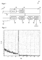
- an exemplary histogram shows a plurality of, for example, a thousand individual light durations.
- the bins on the X-axis are time intervals of possible light propagation times, here in arbitrary units, while the Y-axis represents the associated number of recorded individual run times.
- the histogram is a distribution of the measured individual run times.
- the histogram shows a clear maximum, which is detected with the naked eye approximately in the 175th bin and is clearly different from annoying, caused by ambient light and other disruptive single-time delays.
- the maximum could be located with an algorithm and from this the distance of the object can be determined.
- this requires significant memory space for the histogram, especially if one imagines that such a histogram would have to be stored in a 3D image sensor for each pixel.
- a histogram as in FIG. 2 shown just not built and saved. Rather, the evaluation is based on the fact that the individual light propagation times accumulate near the maximum and measurement events of disturbance events with the aid of a filter criterion derived from this knowledge can already be distinguished during the detection of individual light durations.
- FIG. 3 shows a block diagram of the evaluation in the receive path 16 in a first embodiment.
- a single light transit time measuring unit 28 here is a TDC.
- digital single run times are made available sequentially from the individual measurements.
- the TDC is started by emitting the single light pulse 22 and stopped upon receipt of the remitted individual light pulse 24 and determines the elapsed time, for example, with a kind of counter, based on a very high frequency clock of, for example, 20 GHz.
- Corresponding TDC architectures are known per se in the literature.
- a measured single light transit time is transferred from the single light transit time measuring unit 28 to a buffer 34 and to a filter 36.
- the buffer 34 remembers at least one previous single time running time as a reference value, for example, the most recently passed individual time delay or a history of several previous individual time delays.
- the buffer 34 is also connected to the filter 36 via a multiplexer 38.
- the filter 36 decides on the basis of a comparison of the currently measured individual light running time with one or more reference values from the buffer 34, if the measured single light running time within a time window coincides with at least one previously measured single light running time and is passed to an accumulator connected to the filter 40 or if they singular disturbance event is discarded.
- those individual light delays that have successfully passed through the filter 36 are summed up and counted. From this, the distance to the object is calculated as the result, for example by averaging. This result can also be passed as a further reference value via the multiplexer 38 to the filter 36.
- the measuring method in the reception path 16 according to FIG. 3 then, for example, runs as follows. At the beginning of the measurement, the accumulator and counter are reset to zero. At least the first single light running time is stored only in the buffer 34, depending on the filter criteria for its initialization and a larger number of initial individual light delays is needed.
- the next individual light running time is compared with its reference values. For example, the amount difference is formed and compared with a threshold. Only if the single light run time to be evaluated is close enough to the single light run time stored as a reference value is it passed on. Alternatively, one compares with n stored individual light transit times and requires a sufficient match in m, m ⁇ n , of these comparisons.
- the multiplexer 38 connects the buffer 34 with the filter 36 in this first measurement phase.
- the first measuring phase ends at a certain counter reading, for example after one hundred individual run times have been accumulated.
- the multiplexer 38 then switches over and now transfers the intermediate result of the measured value for the distance to the object as a reference value to the filter 36.
- This intermediate result can be the only reference value in the following second measurement phase or taken into account in addition to the history from the buffer 34.
- the filter 36 otherwise operates as before and compares whether a single light run time to be evaluated is close enough to the reference values.
- the measurement is completed and the result is available at the output of the accumulator 40. It may still be converted to a more familiar unit by the speed of light.
- a further variant consists of not selecting the threshold in the filter 36 statically, but dynamically adapting it, in particular narrowing as a fixed function or table as a function of the count in the accumulator 40 or depending on the standard deviation of the already filtered or accumulated individual run delays.
- the filter 36 may be implemented as a subtractor to form difference and magnitude, the accumulator 40 as a two-register adder for sum and count, the single-register latch 34, and the multiplexer 38 as gate logic.
- the filter 36 may be implemented as a subtractor to form difference and magnitude, the accumulator 40 as a two-register adder for sum and count, the single-register latch 34, and the multiplexer 38 as gate logic.
- 2 (b + ln (n) / ln (2)) 40 satisfy 1-bit registers.
- FIG. 4 shows a block diagram of another embodiment of the evaluation in the receive path 16.
- the in FIG. 3 elements still present and denoted by like reference numerals, but configured in more detail for a solution considering a history of, by way of example, the four most recent past events.
- the input quantity are furthermore the events x (z) coming from the single light transit time measurement unit 28. They are stored in the designed as a sliding memory with shift registers 42 intermediate memory 34.
- the shift registers accordingly contain a history of the four most recently transmitted individual run times.
- the filter 36 has a total of five subtraction stages 44.
- the upper four of these subtracting stages 44 receive as inputs in each case a reference value from the buffer 34 and the current individual light transit time from the individual light transit time measuring unit 28.
- the lowest subtraction stage 44a differs in that the intermediate result of the accumulator 40 is supplied as the reference value.
- the magnitude difference is compared with a threshold ⁇ to determine whether the single light run time and the reference value are in the predetermined time window.
- the threshold ⁇ need not be fixed, but can be taken from the table 46 and vary, for example, with increasing count n in the accumulator 40 or the variance of the previously determined there common measured value.
- the outputs of the subtracting stages 44, 44a are respectively applied to one input of an AND gate 46.
- the other input is ONE via the multiplexer 38 in the first measurement phase and becomes NULL in the second measurement phase.
- the change between the measuring phases is determined in a measuring phase comparator 48 in that the counter reading n has reached or exceeded a predetermined threshold b. Note the inversion at the second input of the lowermost AND gate 46a. It is thereby achieved that in the first measuring phase the individual light running times from the intermediate memory 34 and later the intermediate result of the accumulator 40 as a reference value are taken into account.
- the outputs of the AND gates 46 are applied to the inputs of a filter comparator 50, which checks whether at least one input is ONE and thus indicates that the single light transit time agrees sufficiently well with at least one reference value.
- a sharper criterion ⁇ m can also be selected.
- the output of the filter comparator 50 is connected to an input of a further AND gate 52 whose other input receives a clock corresponding to the sequence of individual light pulses.
- the clock is therefore forwarded as the result of the filter 36 from the further AND gate 52 to an enable input of an adder 42 and to a counter 44 of the accumulator 40, if the single light transit time coincides with the reference value within the time window specified by ⁇ . Therefore, only individual light delays are summed up and counted, which the filter 36 selects.
- the measured value block 32 finally determines the respective mean value as the quotient of the accumulated individual light running times of the adder 42 and the counter reading of the counter 44. A comparison of the count with a termination criterion for the end of the measurement after, for example, a thousand individual measurements is not shown. A reset 54, the accumulator 40 can be reset for a new measurement.
Abstract
Es wird ein optoelektronischer Sensor zur Messung der Entfernung zu einem Objekt in einem Überwachungsbereich (12) angegeben, der einen Lichtsender (20) zum Aussenden einer Folge von Einzellichtpulsen (22) in den Überwachungsbereich (12), einen Lichtempfänger (26) mit mindestens einem Lichtempfangselement zum Empfang der von dem Objekt reflektierten oder remittierten Einzellichtpulse (24), eine Einzellichtlaufzeitmesseinheit (28) zur Bestimmung einer Folge von Einzellichtlaufzeiten der Einzellichtpulse (22, 24) als Dauer zwischen einem Sendezeitpunkt des jeweiligen Einzellichtpulses (22) und dessen von dem Lichtempfangselement (26) erfassten Empfangszeitpunkt sowie eine Auswertungseinheit (30, 32) aufweist, die dafür ausgebildet ist, Einzellichtlaufzeiten zu akkumulieren und daraus einen gemeinsamen Messwert für den Abstand zu bestimmen. Dabei weist die Auswertungseinheit (30) ein Filter (36) auf, um eine Einzellichtlaufzeit nur dann zu akkumulieren, wenn sie innerhalb eines Zeitfensters mit einer vorhergehenden Einzellichtlaufzeit übereinstimmt.An optoelectronic sensor for measuring the distance to an object in a surveillance area (12) is provided, which has a light transmitter (20) for emitting a sequence of individual light pulses (22) into the surveillance area (12), a light receiver (26) having at least one A light receiving element for receiving the individual light pulses (24) reflected or remitted by the object, a single light transit time measuring unit (28) for determining a sequence of individual light propagation times of the individual light pulses (22, 24) as duration between a transmission time of the respective individual light pulse (22) and that of the light receiving element ( 26) detected receiving time and an evaluation unit (30, 32) which is adapted to accumulate individual light durations and to determine therefrom a common measurement value for the distance. In this case, the evaluation unit (30) on a filter (36) to accumulate a single light runtime only if it coincides within a time window with a previous single light running time.
Description
Die Erfindung betrifft einen optoelektronischen Sensor und ein Verfahren zur Messung der Entfernung zu einem Objekt in einem Überwachungsbereich nach dem Oberbegriff von Anspruch 1 beziehungsweise 13.The invention relates to an optoelectronic sensor and a method for measuring the distance to an object in a surveillance area according to the preamble of
In einem entfernungsmessenden optoelektronischen Sensor wird über die reine Objekterfassung hinaus auch eine Distanz zu dem Objekt bestimmt. Mit Hilfe der Distanzinformation werden auch dreidimensionale Bilder oder sogenannte Tiefenkarten erfasst, wenn der Sensor ortsauflösend ist. Ein Scanner tastet dazu mit einem Lichtstrahl den Überwachungsbereich ab, während eine 3D-Kamera für jedes ihrer Pixel statt oder neben der Helligkeitsinformation auch eine Distanzinformation bestimmt.In a distance-measuring optoelectronic sensor, a distance to the object is determined in addition to the pure object detection. With the help of the distance information and three-dimensional images or so-called depth maps are detected when the sensor is spatially resolving. For this purpose, a scanner scans the surveillance area with a light beam, while a 3D camera also determines distance information for each of its pixels instead of or in addition to the brightness information.
Ein herkömmliches Verfahren zur Distanzmessung ist die Lichtlaufzeitmessung. Dabei wird ein kurzer Lichtpuls ausgesandt und die Zeit bis zum Empfang einer Remission oder Reflexion des Lichtpulses gemessen. Um eine höhere Robustheit gegenüber Störereignissen und Rauscheffekten zu gewinnen, ist beispielsweise aus
Derartige Histogrammauswertungen lösen zwar das Messproblem, benötigen aber viel Speicher, denn die gesamte im Messbereich zu erwartende Lichtlaufzeit wird in Bins unterteilt, deren Breite zumindest in der Nähe der angestrebten Messauflösung liegt. Soll die Entfernungsmessung ortsauflösend sein, wie in einer 3D-Kamera, so skaliert dieser Speicherbedarf noch mit der Anzahl Pixel, oder die Erfassungszeit steigt zur Vermeidung des erhöhten Speicherbedarfs durch sequentielle Verarbeitung der Pixel ganz erheblich an. Besonders hinderlich ist das für die Entwicklung kostengünstiger integrierter Auswertungsbausteine etwa in Form eines ASICs (Application Specific Integrated Circuit). Die zahlreichen Speicherzellen sind bei dem erläuterten Zählvorgang über Histogramme flächenbestimmend und zudem geschwindigkeitslimitierend.Although such histogram evaluations solve the measurement problem, but require a lot of memory, because the total expected in the measurement range of light transit time is divided into bins whose width is at least close to the desired measurement resolution. If the distance measurement is to be spatially resolving, as in a 3D camera, then this storage requirement still scales with the number of pixels, or the acquisition time increases to avoid the increased memory requirement by sequential processing of the pixels quite considerably. Particularly hindering for the development of cost-effective integrated evaluation modules such as in the form of an ASIC (Application Specific Integrated Circuit). The numerous memory cells are area determining in the explained counting over histograms and also speed limiting.
Die Nachweisempfindlichkeit einfacher Photodioden genügt in vielen Anwendungsfällen nicht. In einer Lawinenphotodiode (APD, Avalanche Photo Diode) löst das einfallende Licht einen kontrollierten Lawinendurchbruch (Avalanche Effect) aus. So werden die von einfallenden Photonen erzeugten Ladungsträger vervielfacht, und es entsteht ein Photostrom, der zu der Lichtempfangsintensität proportional, dabei aber wesentlich größer ist als bei einer einfachen PIN-Diode. Im sogenannten Geiger-Modus ist die Lawinenphotodiode oberhalb der Durchbruchspannung vorgespannt, so dass bereits ein einziger, durch ein einzelnes Photon freigesetzter Ladungsträger eine Lawine auslösen kann, die dann aufgrund der hohen Feldstärke sämtliche verfügbaren Ladungsträger rekrutiert. Die Lawinenphotodiode zählt somit wie der namensgebende Geigerzähler Einzelereignisse. Lawinenphotodioden im Geiger-Modus werden auch als SPAD (Single-Photon Avalanche Diode) bezeichnet.The detection sensitivity of simple photodiodes is not sufficient in many applications. In an avalanche photodiode (APD, Avalanche Photo Diode) the incident light triggers a controlled avalanche effect. Thus, the charge carriers generated by incident photons are multiplied, and a photocurrent is produced which is proportional to the light reception intensity but much larger than that of a simple PIN diode. In the so-called Geiger mode, the avalanche photodiode is biased above the breakdown voltage, so that even a single, released by a single photon charge carrier can trigger an avalanche, which then recruits all available charge carriers due to the high field strength. The avalanche photodiode thus counts as the eponymous Geiger counter individual events. Geiger mode avalanche photodiodes are also referred to as SPAD (Single-Photon Avalanche Diode).
Die hohe Empfindlichkeit der SPADs bringt auch Nachteile mit sich, da im Grenzfall schon ein einziges störendes Photon oder internes Rauschereignis das gleiche Signal liefert wie ein ausgeprägtes Nutzsignal. Eine vielfache Messwiederholung und gemeinsame Auswertung ist deshalb gerade bei Verwendung von SPADs sinnvoll.The high sensitivity of the SPADs also brings disadvantages, since in the limiting case even a single disturbing photon or internal noise event delivers the same signal as a pronounced useful signal. A multiple measurement repetition and joint evaluation is therefore useful, especially when using SPADs.
Es ist deshalb Aufgabe der Erfindung, eine einfachere Auswertung für ein Pulsmittelungsverfahren anzugeben.It is therefore an object of the invention to provide a simpler evaluation for a pulse averaging process.
Diese Aufgabe wird durch einen optoelektronischen Sensor und ein Verfahren zur Messung der Entfernung zu einem Objekt in einem Überwachungsbereich nach Anspruch 1 beziehungsweise 13 gelöst. Es wird für eine wiederholte Einzelmessung eine Folge von Einzellichtpulsen ausgesandt, wieder empfangen und die jeweilige Einzellichtlautzeit bestimmt, so dass eine entsprechende Folge von Messwerten der Einzelmessungen entsteht. Die Einzelmessungen werden daraufhin akkumuliert ausgewertet, um über einen gemeinsamen Messwert für den Abstand insgesamt eine höhere Genauigkeit zu erzielen. Der Grundgedanke der Erfindung ist dann, durch Rauschereignisse erzeugte Einzellichtlaufzeiten direkt während des Akkumulierens zu erkennen und auszufiltern. Dazu werden beim Akkumulieren nur näherungsweise untereinander gleiche Einzellichtlaufzeiten berücksichtigt. Das fußt auf der Annahme, dass es eine relativ große Anzahl Einzellichtlaufzeiten gibt, die zumindest annähernd dem tatsächlichen Abstand entsprechen, während Rauschereignisse eher singulär auftreten. Insbesondere wird eine Einzellichtlaufzeit nur berücksichtigt, wenn sie mit zumindest einer früheren Einzellichtlaufzeit bis auf eine durch ein Zeitfenster vorgegebene Toleranz übereinstimmt. Die frühere Einzellichtlaufzeit ist beispielsweise der direkte Vorgänger in der Folge, es kann aber auch ein früherer Vorgänger sein beziehungsweise es können mehrere Vorgänger berücksichtigt werden. Die Übereinstimmung kann sich auch auf abgeleitete Größen wie beispielsweise Entfernungswerte beziehen.This object is achieved by an optoelectronic sensor and a method for measuring the distance to an object in a surveillance area according to
Die Erfindung hat den Vorteil, dass nach einem ähnlichen Gedanken wie bei einer Histogrammauswertung eine hohe Messgenauigkeit erreicht wird, ohne jedoch das speicherintensive Histogramm tatsächlich zu bilden. Der Nachteil des hohen Speicherbedarfs entfällt deshalb. Es ist nur ein minimaler Hardwareaufwand erforderlich, mit dem eine schnelle und ohne Weiteres echtzeitfähige Auswertung möglich ist, da die Einzellichtlaufzeiten direkt verarbeitet werden und deshalb nicht mehr im Nachgang ein gesammeltes Histogramm untersucht werden muss.The invention has the advantage that after a similar thought as in a histogram evaluation, a high accuracy of measurement is achieved, but without actually forming the memory-intensive histogram. The disadvantage of the high storage requirements is therefore eliminated. There is only a minimal amount of hardware required, with a fast and readily real-time capable evaluation is possible, since the individual light durations are processed directly and therefore no longer a collected histogram must be examined.
Die Auswertungseinheit weist bevorzugt einen Akkumulator, insbesondere einen Addierer, zum Aufsummieren von Einzellichtlaufzeiten und einen Zähler für die Anzahl aufsummierter Einzellichtlaufzeiten auf. So werden die zahlreichen Einzellichtlaufzeiten als eine Summe gespeichert und dabei direkt einer gemeinsamen Auswertung zugeführt. Für die Implementierung genügt ein einfacher Addierer mit zwei Registern für Summe und Zählerstand. Der Quotient aus den aufsummierten Einzellichtlaufzeiten und dem Zählerstand bildet den gemeinsamen Messwert. Das gilt für jeden Zählerstand in Form eines Zwischenwerts, wobei der Zähler auch für eine Schwellenbetrachtung genutzt werden kann, um die Messung zu beenden. So wird beispielsweise so lange aufsummiert, bis tausend oder eine beliebige andere vorgegebene Anzahl Einzellichtlaufzeiten aufsummiert wurden.The evaluation unit preferably has an accumulator, in particular an adder, for summing up individual light durations and a counter for the number of summed individual light durations. Thus, the numerous individual time delays are stored as a sum and thereby fed directly to a common evaluation. For the implementation, a simple adder with two registers for sum and count suffices. The quotient of the accumulated individual run times and the counter reading form the common measured value. This applies to each meter reading in the form of an intermediate value, wherein the meter can also be used for a threshold consideration to end the measurement. For example, the total is accumulated until a thousand or any other predetermined number of individual run times have been added up.
In der Auswertungseinheit ist bevorzugt ein Zählerstand vorgebbar, ab dem das Filter zusätzlich oder alternativ eine Einzellichtlaufzeit nur dann akkumulieren lässt, wenn sie innerhalb des Zeitfensters mit dem bisherigen gemeinsamen Messwert übereinstimmt. Ab einem Zwischenstand, beispielsweise bei 10% oder irgendeiner anderen Grenze der insgesamt aufzusummierenden Einzellichtlaufzeiten, ändert sich in dieser Ausführungsform das Filterkriterium. Es wird nicht mehr allein die Koinzidenz von Einzellichtlaufzeiten betrachtet, sondern das bisher erreichte Messergebnis fließt zusätzlich ein oder ersetzt dieses Kriterium. Denkbar ist dabei, das bisherige Messergebnis umso stärker zu gewichten, je höher der Zählerstand ist. Wenn Übereinstimmung mit dem Messergebnis innerhalb des Zeitfensters das einzige Kriterium werden soll, kann die Umschaltung mit einem Multiplexer erfolgen.In the evaluation unit is preferably a count can be specified, from which the filter additionally or alternatively accumulate a single light running time only if it coincides within the time window with the previous common measured value. From an intermediate state, for example at 10% or any other limit of the individual light durations to be summed up overall, the filter criterion changes in this embodiment. It is no longer just the coincidence of individual delays but the previously achieved measurement result additionally flows in or replaces this criterion. It is conceivable that the higher the meter reading is, the greater the weighting of the previous measurement result. If agreement with the measurement result within the time window is to be the only criterion, the switchover can be performed with a multiplexer.
Das Filter weist bevorzugt mindestens eine Subtrahier-Stufe auf, um eine Betragsdifferenz von Einzellichtlaufzeiten zu bilden und mit dem Zeitfenster zu vergleichen. In dieser Implementierung bildet das Filter vorzugsweise die Differenz der aktuell zu bewertenden Einzellichtlaufzeit mit einer früher erfassten Einzellichtlaufzeit oder einem daraus generierten Referenzwert, und nur wenn der Betrag dieser Differenz in einem Schwellenvergleich klein genug ist, wird die aktuelle Einzellichtlaufzeit akkumuliert. Damit wird das Filter mit sehr einfachen Bauteilen umgesetzt.The filter preferably has at least one subtracting stage to form an amount difference of individual light delays and to compare it with the time window. In this implementation, the filter preferably forms the difference of the single light run time currently to be evaluated with an earlier detected single light run time or a reference value generated therefrom, and only if the amount of that difference is small enough in a threshold comparison is the current single light run time accumulated. This implements the filter with very simple components.
Die Auswertungseinheit weist bevorzugt einen Zwischenspeicher für mindestens eine vorhergehende Einzellichtlaufzeit auf. Das Filter kann so auf eine frühere Einzellichtlaufzeit zurückgreifen, um mit der durch das Zeitfenster gegebenen Toleranz übereinstimmende Einzellichtlaufzeiten zu erkennen. Je nach Auslegung von Zwischenspeicher und Filter wird dabei nur eine frühere Einzellichtlaufzeit oder eine längere Historie zwischengespeichert und berücksichtigt.The evaluation unit preferably has an intermediate memory for at least one preceding individual time delay. The filter can thus fall back to an earlier single-light runtime in order to recognize the individual light transit times that match the tolerance given by the time window. Depending on the design of the buffer and the filter, only an earlier single runtime or a longer history is buffered and taken into account.
Der Zwischenspeicher ist bevorzugt als Schiebespeicher für mehrere vorhergehende Einzellichtlaufzeiten ausgebildet, und das Filter lässt eine Einzellichtlaufzeit nur dann akkumulieren, wenn sie mit zumindest einer der gespeicherten vorhergehenden Einzellichtlaufzeiten innerhalb des Zeitfensters übereinstimmt. Die den Schiebespeicher nach und nach durchlaufenden Einzellichtlaufzeiten bilden eine auf sehr einfache Weise gespeicherte Historie. Das Filter weist mehrere Zweige auf, vorzugsweise parallel und so viele wie Speicherplätze im Schiebespeicher, um eine zu bewertende Einzellichtlaufzeit mit den zwischengespeicherten Einzellichtlaufzeiten zu vergleichen. Es wird dann zur Berücksichtigung beim Akkumulieren eine Übereinstimmung mit einer oder mehreren der zwischengespeicherten Einzellichtlaufzeiten gefordert.The buffer is preferably designed as a shift memory for a plurality of preceding individual light delays, and the filter can accumulate a single light transit time only if it coincides with at least one of the stored previous individual light delays within the time window. The individual memory run times that gradually pass through the sliding memory form a history stored in a very simple manner. The filter has a plurality of branches, preferably in parallel and as many as memory locations in the shift memory, in order to compare an individual light transit time to be evaluated with the buffered individual light transit times. It is then required for consideration in accumulating a match with one or more of the cached individual time delays.
Die Auswertungseinheit ist bevorzugt dafür ausgebildet, das Zeitfenster im Verlauf des Akkumulierens von Einzellichtlaufzeiten zu variieren. Vorzugsweise wird das Zeitfenster enger. Die Ausführungsform mit variablem Zeitfenster ist besonders vorteilhaft im Zusammenhang mit einer Umschaltung des Filters auf den bisher bestimmten gemeinsamen Messwert. Das Zeitfenster konvergiert dann auf eine Häufung ähnlicher Einzellichtlaufzeiten, und nachdem dies relativ schnell grob lokalisiert ist, wird über die weiteren Einzellichtlaufzeiten die Genauigkeit erhöht. Dabei würden die durch ein zu grobes Zeitfenster noch berücksichtigten Einzellichtlaufzeiten das erreichte Messergebnis nur noch stören.The evaluation unit is preferably designed to vary the time window in the course of the accumulation of individual light durations. Preferably, the time window becomes narrower. The variable time window embodiment is particularly advantageous in connection with a changeover of the filter to the previously determined common Reading. The time window then converges to an accumulation of similar single light durations, and after this is roughly localized relatively quickly, the accuracy is increased over the further single light durations. At the same time, the individual running times, which were still taken into account by a coarse time window, would only disturb the measurement result achieved.
Die Auswertungseinheit passt das Zeitfenster bevorzugt an den Zählerstand und/oder die Varianz des gemeinsamen Messwerts an. Eine Anpassung an den Zählerstand entspricht der soeben erläuterten Erwartung, dass ein grober Messwert schnell bestimmt ist. Die Varianz ist ein Maß für die Übereinstimmung der beitragenden Einzellichtlaufzeiten. Ist sie vergleichsweise klein, so darf angenommen werden, dass weiter abliegende Einzellichtlaufzeiten Störereignisse sind, die dann mit zunehmender Schärfe im Verlauf der weiteren Messung ignoriert werden. Da vorzugsweise die Einzellichtlaufzeiten erfindungsgemäß gerade nicht gespeichert werden, sollte für eine Bestimmung der jeweiligen Varianz außer der Summe der Einzellichtlaufzeiten auch eine Summe der quadrierten Einzellichtlaufzeiten akkumuliert werden. Das passende Zeitfenster für einen Zählerstand und/oder eine Varianz kann in einer Funktion oder Tabelle vorgegeben werden.The evaluation unit preferably adjusts the time window to the count and / or the variance of the common measured value. An adaptation to the counter reading corresponds to the just-explained expectation that a rough measured value is determined quickly. The variance is a measure of the correspondence of the contributing individual delays. If it is comparatively small, it may be assumed that further individual light propagation delays are interference events which are then ignored with increasing sharpness in the course of the further measurement. Since preferably the individual light delays are not stored according to the invention, a sum of the squared individual light durations should be accumulated in addition to the sum of the individual light durations for a determination of the respective variance. The appropriate time window for a count and / or a variance can be specified in a function or table.
Die Einzellichtlaufzeitmesseinheit weist bevorzugt einen TDC (Time-to-Digital-Converter) auf. Das ist ein bekanntes und relativ einfaches Bauteil, das mit hoher zeitlicher Auflösung Einzellichtlaufzeiten bestimmen kann. Der TDC wird vorzugsweise zum Sendezeitpunkt gestartet und zum Empfangszeitpunkt durch den empfangenen Einzellichtpuls gestoppt.The single light transit time measuring unit preferably has a TDC (time-to-digital converter). This is a well-known and relatively simple component, which can determine with a high temporal resolution individual light transit times. The TDC is preferably started at the time of transmission and stopped at the time of reception by the received individual light pulse.
Der Lichtempfänger weist bevorzugt eine Vielzahl von Lichtempfangselementen und mehrere den Lichtempfangselementen einzeln oder gruppenweise zugeordnete Einzellichtlaufzeitmesseinheiten auf. Die Lichtempfangselemente sind dabei vorzugsweise linien- oder matrixartig angeordnet. Es gibt dann verschiedene Varianten der Verschaltung. Im einfachsten Fall wird lediglich über alle Lichtempfangselemente gemittelt. Durch zeitliche Mittelung über die Einzellichtpulse und örtliche Mittelung über die Lichtempfangselemente wird dann ein zuverlässigerer Messwert für den Abstand des Objekts bestimmt. Alternativ wird jedes Lichtempfangselement einzeln ausgewertet und ein Messwert für den Abstand des Objekts bestimmt. Das ergibt einen 3D-Bildsensor. In einer Art Mischform werden mehrere Lichtempfangselemente in einer Mittelung zusammengefasst. Auch das ist ein 3D-Bildsensor, dessen Auflösung jedoch gegenüber der Gesamtzahl Lichtempfangselemente vermindert ist und der dafür in seinen effektiven Bildpunkten einen zuverlässigeren Messwert für den Abstand des Objekts liefert.The light receiver preferably has a plurality of light receiving elements and a plurality of individual light transit time measuring units individually or in groups assigned to the light receiving elements. The light-receiving elements are preferably arranged in a line or matrix. There are then different variants of the interconnection. In the simplest case, it is only averaged over all light-receiving elements. By temporal averaging over the individual light pulses and local averaging over the light receiving elements, a more reliable measured value for the distance of the object is then determined. Alternatively, each light-receiving element is evaluated individually and a measured value for the distance of the object is determined. This results in a 3D image sensor. In a kind of hybrid form, several light receiving elements are combined in one averaging. That too is a 3D image sensor, but its resolution is opposite the total number of light-receiving elements is reduced and that provides a more reliable measurement of the distance of the object in its effective pixels.
Die Lichtempfangselemente sind bevorzugt in einem Geiger-Modus betriebene Lawinenphotodioden. Diese auch als SPADs bezeichneten Lichtempfangselemente wurden in der Einleitung schon kurz beschrieben. Die APDs (Avalanche Photo Diode) sind oberhalb ihrer Durchbruchsspannung vorgespannt, und der Lawinenstrom kann schon durch ein einziges Photon ausgelöst werden. SPADs sind daher extrem sensitiv, zugleich aber auch anfällig für Fehlmessungen, denn die Einzellichtlaufzeit kann fehlerhaft auf die Registrierung eines Fremdlichtphotons zurückgehen und dann gänzlich unkorreliert mit dem Abstand des Objekts sein. Aus diesem Grund ist ein statistischer Ansatz mit Fremdereigniserkennung wie die erfindungsgemäße Auswertung von Einzellichtlaufzeiten für SPADs besonders geeignet.The light receiving elements are preferably avalanche photodiodes operated in a Geiger mode. These light receiving elements, also referred to as SPADs, have already been briefly described in the introduction. The APDs (Avalanche Photo Diode) are biased above their breakdown voltage, and the avalanche current can be triggered by a single photon. SPADs are therefore extremely sensitive, but at the same time susceptible to erroneous measurements, because the single light transit time can go back to the registration of an extraneous light photon incorrectly and then be completely uncorrelated with the distance of the object. For this reason, a statistical approach with foreign event detection as the inventive evaluation of single light transit times for SPADs is particularly suitable.
Die Auswertungseinheit ist bevorzugt zumindest teilweise auf dem Lichtempfänger integriert. Beispielsweise ist der Lichtempfänger ein ASIC mit sowohl den Lichtempfangselementen als auch zumindest Teilen der Auswertung. Die Schaltungen für die erfindungsgemäße Auswertung können ausgesprochen einfach ausgelegt werden. Es werden kaum Speicherzellen gebraucht, und deshalb entsteht wenig Flächenbedarf. Das erleichtert die Integration erheblich. Vorzugsweise kann sogar in den Pixeln, also lokal zu jedem Lichtempfangselement oder zu Gruppen von Lichtempfangselementen, eine zugehörige Auswertungsschaltung integriert werden. Diese Auswertungsschaltung kann nur die Einzellichtlaufzeitmesseinheit, aber auch zusätzlich den Akkumulator, Zähler und Filter umfassen. Wegen der einfachen Schaltungen ist dabei ein Füllfaktor, d.h. Verhältnis lichtempfindliche Fläche zu Gesamtfläche des Pixels, von mehr als 20% erreichbar.The evaluation unit is preferably at least partially integrated on the light receiver. For example, the light receiver is an ASIC with both the light receiving elements and at least parts of the evaluation. The circuits for the evaluation according to the invention can be designed very simply. Hardly any memory cells are needed, which means there is little need for space. This facilitates the integration considerably. Preferably, even in the pixels, that is local to each light receiving element or to groups of light receiving elements, an associated evaluation circuit can be integrated. This evaluation circuit may include only the single light transit time measuring unit, but also in addition the accumulator, counter and filter. Because of the simple circuits, a fill factor, i. Ratio of photosensitive area to total area of the pixel, reachable by more than 20%.
Das erfindungsgemäße Verfahren kann auf ähnliche Weise weitergebildet werden und zeigt dabei ähnliche Vorteile. Derartige vorteilhafte Merkmale sind beispielhaft, aber nicht abschließend in den sich an die unabhängigen Ansprüche anschließenden Unteransprüchen beschrieben.The method according to the invention can be developed in a similar manner and shows similar advantages. Such advantageous features are described by way of example but not exhaustively in the subclaims following the independent claims.
Die Erfindung wird nachstehend auch hinsichtlich weiterer Merkmale und Vorteile beispielhaft anhand von Ausführungsformen und unter Bezug auf die beigefügte Zeichnung näher erläutert. Die Abbildungen der Zeichnung zeigen in:
- Fig. 1
- ein Blockdiagramm eines Messkerns zum Bestimmen der Lichtlaufzeit aus einer Folge von Einzellichtpulsen;
- Fig. 2
- ein beispielhaftes Histogramm einer Vielzahl mit Einzelpulsen gemessener Lichtlaufzeiten;
- Fig. 3
- ein Blockschaltbild einer ersten Ausführungsform einer Auswertungseinheit zur Bestimmung der Lichtlaufzeit aus zumindest annähernd übereinstimmenden Einzelmessungen; und
- Fig. 4
- ein Blockschaltbild einer weiteren Ausführungsform zur Bestimmung der Lichtlaufzeit aus zumindest annähernd übereinstimmenden Einzelmessungen mit Betrachtung einer längeren Historie.
- Fig. 1
- a block diagram of a measuring core for determining the light transit time from a sequence of individual light pulses;
- Fig. 2
- an exemplary histogram of a plurality of measured with individual pulses light transit times;
- Fig. 3
- a block diagram of a first embodiment of an evaluation unit for determining the light transit time from at least approximately matching individual measurements; and
- Fig. 4
- a block diagram of another embodiment for determining the light transit time from at least approximately matching individual measurements with a view of a longer history.
In dem Sendepfad 14 wird mit einem Pulsgenerator 18 eine Folge von kurzen Einzelpulsen erzeugt. Die Pulspausen und -längen können dabei variiert werden, beispielsweise für eine Codierung oder Anpassung an Umgebungsverhältnisse. Für die Belange der Erfindung genügt jedoch die einfachere Vorstellung einer gleichmäßigen Sequenz von Einzelpulsen, die untereinander genügend zeitlichen Abstand haben, um die jeweiligen Messungen nicht zu beeinflussen.In the
Aus dem elektronischen Sendesignal mit der Pulsfolge erzeugt ein Lichtsender 20, beispielsweise eine LED oder Laserdiode, eine entsprechende Folge von Einzellichtpulsen 22, die in den Überwachungsbereich 12 ausgesandt werden. Treffen die Einzellichtpulse 22 dort auf ein Objekt, so kehrt ein entsprechender reflektierter oder remittierter Einzellichtpuls 24 zu dem Sensor mit dem Messkern 10 zurück und trifft auf den Lichtempfänger 26, der daraus ein elektronisches Empfangssignal erzeugt.From the electronic transmission signal with the pulse sequence, a
Der Lichtempfänger 26 kann eine einfache Photodiode oder APD sein, ist jedoch bevorzugt SPAD-basiert. Der Lichtempfänger 26 weist mindestens ein Lichtempfangselement auf, insbesondere eine große Anzahl Lichtempfangselemente in Linienoder Matrixanordnung. Dabei kann die Ortsauflösung erhalten bleiben und so ein 3D-Bildsensor entstehen, oder es erfolgt eine örtliche Mittelung über mehrere oder alle Lichtempfangselemente. Die erfindungsgemäße Auswertung einer Folge von Empfangssignalen aus Einzellichtpulsen ist unabhängig davon, wie diese Ereignisse registriert wurden.The
Als ersten Auswertungsschritt bestimmt eine Einzellichtlaufzeitmesseinheit 28 die jeweilige Einzellichtlaufzeit zwischen Aussenden eines Einzellichtpulses 22 und Empfangen des zugehörigen remittierten Einzellichtpulses 24. Die Einzellichtlaufzeitmesseinheit 28 ist beispielsweise ein TDC oder ein Block von TDCs.As a first evaluation step, an individual light transit
In weiteren Auswertungsschritten werden die Einzellichtlaufzeiten in einem Akkumulator 30 gesammelt. Dabei werden mit Hilfe eines Filters nur bestimmte Einzellichtlaufzeiten berücksichtigt, wie weiter unten anhand der
Aus den akkumulierten Einzellichtlaufzeiten wird dann in einem Messwertblock 32 zur Bestimmung eines gemeinsamen Messwerts der Abstand zu dem Objekt bestimmt. Dazu wird beispielsweise der Mittelwert gebildet. Übrigens wird in dieser Beschreibung zwischen der Lichtlaufzeit und dem Abstand oft nicht unterschieden, da sie sich über die konstante Lichtgeschwindigkeit nur in der Einheit voneinander unterscheiden.The distance to the object is then determined from the accumulated individual light propagation times in a measured
In einer bevorzugten Ausführungsform ist der Empfangspfad 16 auf einem ASIC integriert. Dabei können eigene Blocks für die Lichtempfangselemente 26 einerseits und die Auswertungsschaltungen 28, 30, 32 andererseits vorgesehen sein. Vorzugsweise sind jedoch zumindest jeweilige Einzellichtlaufzeitmesseinheit 28 direkt bei den Lichtempfangselementen 26 angeordnet und bilden mit einzelnen Lichtempfangselementen 26 oder Gruppen davon intelligente Pixel. Auch der Akkumulator 30 und der Messwertblock 32 können in diese Pixel integriert werden. Eine übergeordnete Steuerung entscheidet dann, ob und wie die Messergebnisse der Pixel ortsaufgelöst genutzt oder nochmals gemittelt werden. In einer weiteren Ausführungsform wird ein FPGA (Field Programmable Gate Array) eingesetzt, auf dem der Akkumulator 30 und/oder der Messwertblock 32 und gegebenenfalls auch die Einzellichtlaufzeitmesseinheit 28 implementiert ist.In a preferred embodiment, the receive
Das Histogramm zeigt ein eindeutiges Maximum, das mit bloßem Auge ungefähr im 175. Bin erkannt wird und sich klar von störenden, von Umgebungslicht und anderen Störeffekten verursachten Einzellichtlaufzeiten abhebt. Das Maximum könnte mit einem Algorithmus lokalisiert und daraus der Abstand des Objekts ermittelt werden. Allerdings erfordert das erheblichen Speicherbedarf für das Histogramm, besonders wenn man sich vorstellt, dass ein derartiges Histogramm in einem 3D-Bildsensor für jedes Pixel gespeichert werden müsste.The histogram shows a clear maximum, which is detected with the naked eye approximately in the 175th bin and is clearly different from annoying, caused by ambient light and other disruptive single-time delays. The maximum could be located with an algorithm and from this the distance of the object can be determined. However, this requires significant memory space for the histogram, especially if one imagines that such a histogram would have to be stored in a 3D image sensor for each pixel.
Erfindungsgemäß wird deshalb ein Histogramm wie in
Eine gemessene Einzellichtlaufzeit wird von der Einzellichtlaufzeitmesseinheit 28 an einen Zwischenspeicher 34 und an ein Filter 36 übergeben. Der Zwischenspeicher 34 merkt sich mindestens eine frühere Einzellichtlaufzeit als Referenzwert, beispielsweise die jeweils zuletzt übergebene Einzellichtlaufzeit oder eine Historie von mehreren früheren Einzellichtlaufzeiten. Der Zwischenspeicher 34 ist über einen Multiplexer 38 ebenfalls an das Filter 36 angeschlossen.A measured single light transit time is transferred from the single light transit
Das Filter 36 entscheidet anhand eines Vergleichs der aktuell gemessenen Einzellichtlaufzeit mit einem oder mehreren Referenzwerten aus dem Zwischenspeicher 34, ob die gemessene Einzellichtlaufzeit innerhalb eines Zeitfensters mit mindestens einer früher gemessenen Einzellichtlaufzeit übereinstimmt und an einen an das Filter angeschlossenen Akkumulator 40 weitergegeben wird oder ob sie als singuläres Störereignis verworfen wird.The
In dem Akkumulator 40 werden diejenigen Einzellichtlaufzeiten, die das Filter 36 erfolgreich passiert haben, aufsummiert und gezählt. Daraus wird dann der Abstand zu dem Objekt als Ergebnis berechnet, etwa durch Mittelwertbildung. Dieses Ergebnis kann außerdem als weiterer Referenzwert über den Multiplexer 38 dem Filter 36 übergeben werden.In the
Das Messverfahren in dem Empfangspfad 16 gemäß
Sobald der Zwischenspeicher 34 ausreichend gefüllt ist, wird die nächste Einzellichtlaufzeit mit dessen Referenzwerten verglichen. Beispielsweise wird dazu die Betragsdifferenz gebildet und mit einer Schwelle verglichen. Nur wenn die zu bewertende Einzellichtlaufzeit nahe genug an der als Referenzwert gespeicherten Einzellichtlaufzeit liegt, wird sie weitergegeben. Alternativ wird mit n gespeicherten Einzellichtlaufzeiten verglichen und eine ausreichende Übereinstimmung in m, m ≤ n, dieser Vergleiche gefordert. Der Multiplexer 38 verbindet in dieser ersten Messphase den Zwischenspeicher 34 mit dem Filter 36.As soon as the
Eine Einzellichtlaufzeit, die das Filter 36 nicht als singuläres Störereignis verwirft und demnach an den Akkumulator 40 weitergibt, wird dort aufsummiert und zugleich der Zähler erhöht. Als Zwischenergebnis wird am Ausgang des Akkumulators der bisher bestimmte Mittelwert bereitgestellt.An individual light transit time, which does not discard the
Die erste Messphase endet bei einem bestimmten Zählerstand, beispielsweise nachdem hundert Einzellichtlaufzeiten akkumuliert wurden. Dann schaltet der Multiplexer 38 um und übergibt nun das Zwischenergebnis des Messwerts für den Abstand zu dem Objekt als Referenzwert an das Filter 36. Dieses Zwischenergebnis kann in der folgenden zweiten Messphase der einzige Referenzwert sein oder zusätzlich zu der Historie aus dem Zwischenspeicher 34 berücksichtigt werden. Das Filter 36 arbeitet ansonsten wie zuvor und vergleicht, ob eine zu bewertende Einzellichtlaufzeit nahe genug an den Referenzwerten liegt.The first measuring phase ends at a certain counter reading, for example after one hundred individual run times have been accumulated. The
Bei einem weiteren bestimmten Zählerstand, beispielsweise nachdem tausend Einzellichtlaufzeiten akkumuliert wurden, ist die Messung beendet, und das Ergebnis steht am Ausgang des Akkumulators 40 bereit. Es wird möglicherweise noch über die Lichtgeschwindigkeit in eine für den Abstand geläufigere Einheit umgerechnet.At a further specific count, for example, after a thousand individual light durations have been accumulated, the measurement is completed and the result is available at the output of the
Es ist denkbar, auf den Multiplexer 38 zu verzichten und während der gesamten Messung wie in der ersten Messphase nur die Einzellichtlaufzeiten untereinander zu vergleichen. Eine weitere Variante besteht darin, die Schwelle in dem Filter 36 nicht statisch zu wählen, sondern dynamisch anzupassen, insbesondere enger werdend als feste Funktion oder Tabelle in Abhängigkeit von dem Zählerstand in dem Akkumulator 40 oder abhängig von der Standardabweichung der bereits gefilterten beziehungsweise akkumulierten Einzellichtlaufzeiten.It is conceivable to dispense with the
Für die Implementierung dieses Verfahrens genügt ein minimaler Hardwareaufwand. Das Filter 36 kann als Subtrahier-Stufe zur Bildung von Differenz und Betrag, der Akkumulator 40 als Addierer mit zwei Registern für Summe und Zählerstand, der Zwischenspeicher 34 aus nur einem Register und der Multiplexer 38 als Gatterlogik implementiert werden. Weist beispielsweise der TDC der Einzellichtlaufzeitmesseinheit 28 eine Bitbreite von b=10 auf und werden n=1024 Einzellichtlaufzeiten verarbeitet, dann würde ein Histogrammverfahren 2b ln(n)/(2) = 10240 1-Bit-Register verbrauchen. Erfindungsgemäß genügen 2 (b+ln(n)/ln(2)) = 40 1-Bit-Register.For the implementation of this method, a minimal amount of hardware is sufficient. The
Die Eingangsgröße sind weiterhin die von der Einzellichtlaufzeitmesseinheit 28 kommenden Ereignisse x(z). Sie werden in dem als Schiebespeicher mit Schieberegistern 42 ausgebildeten Zwischenspeicher 34 abgelegt. Die Schieberegister enthalten demnach eine Historie der vier zuletzt übergebenen Einzellichtlaufzeiten.The input quantity are furthermore the events x (z) coming from the single light transit
Das Filter 36 weist insgesamt fünf Subtrahier-Stufen 44 auf. Die oberen vier dieser Subtrahier-Stufen 44 erhalten als Eingänge jeweils einen Referenzwert aus dem Zwischenspeicher 34 sowie die aktuelle Einzellichtlaufzeit von der Einzellichtlaufzeitmesseinheit 28. Die unterste Subtrahier-Stufe 44a unterscheidet sich dadurch, dass ihr als Referenzwert das Zwischenergebnis des Akkumulators 40 zugeführt wird. Die Betragsdifferenz wird mit einer Schwelle ε verglichen, um festzustellen, ob Einzellichtlaufzeit und Referenzwert in dem vorgegebenen Zeitfenster liegen. Dabei muss die Schwelle ε nicht fix sein, sondern kann aus der Tabelle 46 entnommen und beispielsweise mit zunehmendem Zählerstand n in dem Akkumulator 40 oder der Varianz des dort bisher ermittelten gemeinsamen Messwerts variieren.The
Die Ausgänge der Subtrahier-Stufen 44, 44a werden jeweils auf einen Eingang eines UND-Gatters 46 gelegt. Der andere Eingang ist über den Multiplexer 38 in der ersten Messphase EINS und wird in der zweiten Messphase NULL. Der Wechsel zwischen den Messphasen wird in einem Messphasenvergleicher 48 dadurch bestimmt, dass der Zählerstand n eine vorgegebene Schwelle b erreicht oder übertroffen hat. Zu beachten ist die Invertierung am zweiten Eingang des untersten UND-Gatters 46a. Dadurch wird erreicht, dass in der ersten Messphase die Einzellichtlaufzeiten aus dem Zwischenspeicher 34 und später das Zwischenergebnis des Akkumulators 40 als Referenzwert berücksichtigt werden.The outputs of the subtracting stages 44, 44a are respectively applied to one input of an AND
Die Ausgänge der UND-Gatter 46 sind auf die Eingänge eines Filtervergleichers 50 gelegt, der prüft, ob mindestens ein Eingang EINS ist und damit anzeigt, dass die Einzellichtlaufzeit mit zumindest einem Referenzwert ausreichend gut übereinstimmt. Hier kann zumindest in der ersten Messphase auch ein schärferes Kriterium ≥ m gewählt werden.The outputs of the AND
Der Ausgang des Filtervergleichers 50 wird mit einem Eingang eines weiteren UND-Gatters 52 verbunden, dessen anderer Eingang einen der Folge der Einzellichtpulse entsprechenden Takt erhält. Der Takt wird deshalb als Ergebnis des Filters 36 von dem weiteren UND-Gatter 52 genau dann an einen Enable-Eingang eines Addierers 42 und an einen Zähler 44 des Akkumulators 40 weitergegeben, wenn die Einzellichtlaufzeit innerhalb des durch ε vorgegebenen Zeitfensters mit dem Referenzwert übereinstimmt. Es werden deshalb nur Einzellichtlaufzeiten aufsummiert und gezählt, die das Filter 36 selektiert.The output of the
Der Messwertblock 32 bestimmt abschließend den jeweiligen Mittelwert als Quotient der aufsummierten Einzellichtlaufzeiten des Addierers 42 und des Zählerstandes des Zählers 44. Ein Vergleich des Zählerstandes mit einem Abbruchkriterium für das Ende der Messung nach beispielsweise tausend Einzelmessungen ist nicht darstellt. Über einen Reset 54 kann der Akkumulator 40 für eine neue Messung zurückgesetzt werden.The measured
Claims (13)
dass die Auswertungseinheit (30) ein Filter (36) aufweist, um eine Einzellichtlaufzeit nur dann zu akkumulieren, wenn sie innerhalb eines Zeitfensters mit einer vorhergehenden Einzellichtlaufzeit übereinstimmt.An optoelectronic sensor for measuring the distance to an object in a surveillance area (12) comprising a light emitter (20) for emitting a train of single light pulses (22) into the surveillance area (12), a light receiver (26) having at least one light receiving element for receiving the from the object reflected or remitted individual light pulses (24), a Einzellichtlaufzeitmessung unit (28) for determining a sequence of individual light transit times of the individual light pulses (22, 24) as the duration between a transmission time of the respective individual light pulse (22) and its from the light receiving element (26) detected time of reception and an evaluation unit (30, 32), which is designed to accumulate individual light durations and to use them to determine a common measured value for the distance, characterized in that
in that the evaluation unit (30) has a filter (36) in order to accumulate a single light transit time only if it coincides within a time window with a preceding individual light transit time.
wobei die Auswertungseinheit (30) einen Akkumulator (40), insbesondere einen Addierer (42), zum Aufsummieren von Einzellichtlaufzeiten und einen Zähler (44) für die Anzahl aufsummierter Einzellichtlaufzeiten aufweist.Sensor according to claim 1,
wherein the evaluation unit (30) comprises an accumulator (40), in particular an adder (42), for summing up individual light delays and a counter (44) for the number of accumulated individual light delays.
wobei in der Auswertungseinheit (30) ein Zählerstand vorgebbar ist, ab dem das Filter (36) zusätzlich oder alternativ eine Einzellichtlaufzeit nur dann akkumulieren lässt, wenn sie innerhalb des Zeitfensters mit dem bisherigen gemeinsamen Messwert übereinstimmt.Sensor according to claim 2,
wherein in the evaluation unit (30) a counter reading can be specified, from which the filter (36) additionally or alternatively accumulates a single light runtime only if it coincides within the time window with the previous common measured value.
wobei das Filter (36) mindestens eine Subtrahier-Stufe (44) aufweist, um eine Betragsdifferenz von Einzellichtlaufzeiten zu bilden und mit dem Zeitfenster zu vergleichen.Sensor according to one of the preceding claims,
wherein the filter (36) comprises at least one subtracting stage (44) for forming an amount difference of single-time delays and comparing them with the time window.
wobei die Auswertungseinheit (30) einen Zwischenspeicher (34) für mindestens eine vorhergehende Einzellichtlaufzeit aufweist.Sensor according to one of the preceding claims,
wherein the evaluation unit (30) has a buffer (34) for at least has a previous single light running time.
wobei der Zwischenspeicher (34) als Schiebespeicher (42) für mehrere vorhergehende Einzellichtlaufzeiten ausgebildet ist und das Filter (36) eine Einzellichtlaufzeit nur dann akkumulieren lässt, wenn sie mit zumindest einer der gespeicherten vorhergehenden Einzellichtlaufzeiten innerhalb des Zeitfensters übereinstimmt.Sensor according to claim 5,
wherein the buffer memory (34) is designed as a shift memory (42) for a plurality of preceding individual light delays and the filter (36) accumulates a single light transit time only if it coincides with at least one of the stored preceding individual light delays within the time window.
wobei die Auswertungseinheit (30, 46) dafür ausgebildet ist, das Zeitfenster im Verlauf des Akkumulierens von Einzellichtlaufzeiten zu variieren.Sensor according to one of the preceding claims,
wherein the evaluation unit (30, 46) is adapted to vary the time window in the course of accumulating individual light durations.
wobei die Auswertungseinheit (30, 46) das Zeitfenster an den Zählerstand und/oder die Varianz des gemeinsamen Messwerts anpasst.Sensor according to claim 7,
wherein the evaluation unit (30, 46) adjusts the time window to the count and / or the variance of the common measured value.
wobei die Einzellichtlaufzeitmesseinheit (28) einen TDC aufweist.Sensor according to one of the preceding claims,
wherein the single light transit time measuring unit (28) has a TDC.
wobei der Lichtempfänger (26) eine Vielzahl von Lichtempfangselementen und mehrere den Lichtempfangselementen einzeln oder gruppenweise zugeordnete Einzellichtlaufzeitmesseinheiten (28) aufweist.Sensor according to one of the preceding claims,
wherein the light receiver (26) comprises a plurality of light receiving elements and a plurality of individual light transit time measuring units (28) assigned to the light receiving elements individually or in groups.
wobei die Lichtempfangselemente in einem Geiger-Modus betriebene Lawinenphotodioden sind.Sensor according to one of the preceding claims,
wherein the light receiving elements are avalanche photodiodes operated in a Geiger mode.
wobei die Auswertungseinheit (30) zumindest teilweise auf dem Lichtempfänger (26), insbesondere zu jedem Lichtempfangselement oder Gruppen von Lichtempfangselementen, integriert ist.Sensor according to one of the preceding claims,
wherein the evaluation unit (30) is at least partially integrated on the light receiver (26), in particular to each light-receiving element or groups of light-receiving elements.
dadurch gekennzeichnet,
dass mit Hilfe eines Filters (36) eine Einzellichtlaufzeit nur dann akkumuliert wird, wenn sie innerhalb eines Zeitfensters mit einer vorhergehenden Einzellichtlaufzeit übereinstimmt.Method for measuring the distance to an object in a monitoring area (12), in which a sequence of individual light pulses (22) in the Monitoring range (12) is emitted, the reflected or remitted from the object individual light pulses (24) are received again, a sequence of individual light transit times of the individual light pulses (22, 24) determined as the duration between a transmission time of the respective individual light pulse (22) and its reception time, the individual run times are accumulated and from this a common measured value for the distance is determined,
characterized,
that with the aid of a filter (36) an individual light transit time is only accumulated if it coincides within a time window with a preceding individual light transit time.
Priority Applications (3)
| Application Number | Priority Date | Filing Date | Title |
|---|---|---|---|
| EP15202272.9A EP3185038B1 (en) | 2015-12-23 | 2015-12-23 | Optoelectronic sensor and method for measuring a distance |
| US15/343,851 US10401482B2 (en) | 2015-12-23 | 2016-11-04 | Optoelectronic sensor and method for measuring a distance |
| JP2016241889A JP6556688B2 (en) | 2015-12-23 | 2016-12-14 | Photoelectric sensor and distance measuring method |
Applications Claiming Priority (1)
| Application Number | Priority Date | Filing Date | Title |
|---|---|---|---|
| EP15202272.9A EP3185038B1 (en) | 2015-12-23 | 2015-12-23 | Optoelectronic sensor and method for measuring a distance |
Publications (2)
| Publication Number | Publication Date |
|---|---|
| EP3185038A1 true EP3185038A1 (en) | 2017-06-28 |
| EP3185038B1 EP3185038B1 (en) | 2018-02-14 |
Family
ID=55024000
Family Applications (1)
| Application Number | Title | Priority Date | Filing Date |
|---|---|---|---|
| EP15202272.9A Active EP3185038B1 (en) | 2015-12-23 | 2015-12-23 | Optoelectronic sensor and method for measuring a distance |
Country Status (3)
| Country | Link |
|---|---|
| US (1) | US10401482B2 (en) |
| EP (1) | EP3185038B1 (en) |
| JP (1) | JP6556688B2 (en) |
Cited By (8)
| Publication number | Priority date | Publication date | Assignee | Title |
|---|---|---|---|---|
| EP3457177A1 (en) * | 2017-09-19 | 2019-03-20 | Kabushiki Kaisha Toshiba | Distance measurement apparatus |
| DE102018109014A1 (en) | 2018-04-17 | 2019-10-17 | Sick Ag | Opto-electronic sensor and method for detecting and determining the distance of an object |
| EP3698172A4 (en) * | 2017-12-08 | 2021-07-28 | Velodyne Lidar USA, Inc. | Systems and methods for improving detection of a return signal in a light ranging and detection system |
| US11550036B2 (en) | 2016-01-31 | 2023-01-10 | Velodyne Lidar Usa, Inc. | Multiple pulse, LIDAR based 3-D imaging |
| US11550056B2 (en) | 2016-06-01 | 2023-01-10 | Velodyne Lidar Usa, Inc. | Multiple pixel scanning lidar |
| US11703569B2 (en) | 2017-05-08 | 2023-07-18 | Velodyne Lidar Usa, Inc. | LIDAR data acquisition and control |
| US11796648B2 (en) | 2018-09-18 | 2023-10-24 | Velodyne Lidar Usa, Inc. | Multi-channel lidar illumination driver |
| US11885958B2 (en) | 2019-01-07 | 2024-01-30 | Velodyne Lidar Usa, Inc. | Systems and methods for a dual axis resonant scanning mirror |
Families Citing this family (24)
| Publication number | Priority date | Publication date | Assignee | Title |
|---|---|---|---|---|
| US10620300B2 (en) | 2015-08-20 | 2020-04-14 | Apple Inc. | SPAD array with gated histogram construction |
| US20180341009A1 (en) | 2016-06-23 | 2018-11-29 | Apple Inc. | Multi-range time of flight sensing |
| US10132921B2 (en) * | 2016-11-02 | 2018-11-20 | Stmicroelectronics (Research & Development) Ltd | Light communications receiver and decoder with time to digital converters |
| US10942257B2 (en) | 2016-12-31 | 2021-03-09 | Innovusion Ireland Limited | 2D scanning high precision LiDAR using combination of rotating concave mirror and beam steering devices |
| DE102017113675B4 (en) * | 2017-06-21 | 2021-11-18 | Sick Ag | Photoelectric sensor and method for measuring the distance to an object |
| DE102017114565A1 (en) * | 2017-06-29 | 2019-01-03 | Osram Opto Semiconductors Gmbh | An optical distance measuring device and method for operating an optical distance measuring device |
| WO2019005260A1 (en) | 2017-06-29 | 2019-01-03 | Apple Inc. | Time-of-flight depth mapping with parallax compensation |
| US10955552B2 (en) * | 2017-09-27 | 2021-03-23 | Apple Inc. | Waveform design for a LiDAR system with closely-spaced pulses |
| KR102403544B1 (en) | 2017-12-18 | 2022-05-30 | 애플 인크. | Time-of-flight sensing using an addressable array of emitters |
| US11808888B2 (en) | 2018-02-23 | 2023-11-07 | Innovusion, Inc. | Multi-wavelength pulse steering in LiDAR systems |
| DE102018203534A1 (en) * | 2018-03-08 | 2019-09-12 | Ibeo Automotive Systems GmbH | Receiver arrangement for receiving light pulses, LiDAR module and method for receiving light pulses |
| US11029397B2 (en) * | 2018-04-20 | 2021-06-08 | Omnivision Technologies, Inc. | Correlated time-of-flight sensor |
| JP6970648B2 (en) * | 2018-08-27 | 2021-11-24 | 株式会社東芝 | Electronic device and distance measurement method |
| EP3683599B1 (en) * | 2019-01-16 | 2022-06-22 | Ibeo Automotive Systems GmbH | Method and device for optically measuring distances |
| KR102604902B1 (en) | 2019-02-11 | 2023-11-21 | 애플 인크. | Depth sensing using sparse arrays of pulsed beams |
| JP7317530B2 (en) | 2019-03-14 | 2023-07-31 | 株式会社東芝 | Distance measuring device, distance measuring method, and signal processing method |
| JP7193413B2 (en) * | 2019-05-10 | 2022-12-20 | 株式会社東芝 | Electronic device and distance measurement method |
| US11500094B2 (en) | 2019-06-10 | 2022-11-15 | Apple Inc. | Selection of pulse repetition intervals for sensing time of flight |
| US11555900B1 (en) | 2019-07-17 | 2023-01-17 | Apple Inc. | LiDAR system with enhanced area coverage |
| JP7379021B2 (en) * | 2019-08-29 | 2023-11-14 | 株式会社東芝 | Distance measuring device, distance measuring method, and speed measuring device |
| US11733359B2 (en) | 2019-12-03 | 2023-08-22 | Apple Inc. | Configurable array of single-photon detectors |
| WO2022141468A1 (en) * | 2020-12-31 | 2022-07-07 | 深圳市速腾聚创科技有限公司 | Detection method for laser radar, computer readable storage medium, and laser radar |
| US11681028B2 (en) | 2021-07-18 | 2023-06-20 | Apple Inc. | Close-range measurement of time of flight using parallax shift |
| GB202113866D0 (en) * | 2021-09-28 | 2021-11-10 | Ams Ag | Time to digital conversion |
Citations (5)
| Publication number | Priority date | Publication date | Assignee | Title |
|---|---|---|---|---|
| US3644043A (en) * | 1969-08-11 | 1972-02-22 | Hughes Aircraft Co | Integrated infrared-tracker-receiver laser-rangefinder target search and track system |
| DE102007013714A1 (en) | 2007-03-22 | 2008-10-02 | Sick Ag | Optoelectronic sensor and method for measuring a distance or a range change |
| US20120075615A1 (en) * | 2009-06-22 | 2012-03-29 | Toyota Motor Europe Nv/Sa | Pulsed light optical rangefinder |
| US20120162632A1 (en) * | 2010-12-22 | 2012-06-28 | Stmicroelectronics (Research & Development) Limited | Real-Time Processing Method and System |
| US20130300838A1 (en) * | 2010-12-23 | 2013-11-14 | Fastree3D S.A. | Methods and devices for generating a representation of a 3d scene at very high speed |
Family Cites Families (12)
| Publication number | Priority date | Publication date | Assignee | Title |
|---|---|---|---|---|
| US4938592A (en) * | 1987-07-28 | 1990-07-03 | Amherst Process Instruments, Inc. | Beam forming and sensing apparatus for aerodynamic particle sizing system |
| JP2002328166A (en) * | 2001-05-01 | 2002-11-15 | Nikon Corp | Ranging device and method |
| JP5617159B2 (en) * | 2008-10-07 | 2014-11-05 | トヨタ自動車株式会社 | Image acquisition apparatus and method |
| FR2940010B1 (en) * | 2008-12-19 | 2011-11-11 | Affflex Europ | DEVICE FOR SAMPLING AN ANIMAL TISSUE SAMPLE |
| KR101722641B1 (en) * | 2010-12-23 | 2017-04-04 | 삼성전자주식회사 | 3D image acquisition apparatus and method of extractig depth information in the 3D image acquisition apparatus |
| JP2014102072A (en) * | 2011-03-08 | 2014-06-05 | National Univ Corp Shizuoka Univ | Signal processing circuit for distance measurement and distance measurement device |
| JPWO2012144344A1 (en) * | 2011-04-18 | 2014-07-28 | 住友電気工業株式会社 | Molten salt battery device |
| EP2708913A1 (en) | 2012-09-18 | 2014-03-19 | Sick Ag | Opto-electronic sensor and object detection method |
| JP6236758B2 (en) * | 2012-10-09 | 2017-11-29 | 株式会社豊田中央研究所 | Optical distance measuring device |
| US10721171B2 (en) * | 2013-06-24 | 2020-07-21 | Vecima Networks Inc. | Data transfer system and corresponding methods |
| EP2824478B1 (en) * | 2013-07-11 | 2015-05-06 | Sick Ag | Optoelectronic sensor and method for detecting and measuring the distance of objects in a monitored area |
| DE102014106465C5 (en) * | 2014-05-08 | 2018-06-28 | Sick Ag | Distance measuring sensor and method for detection and distance determination of objects |
-
2015
- 2015-12-23 EP EP15202272.9A patent/EP3185038B1/en active Active
-
2016
- 2016-11-04 US US15/343,851 patent/US10401482B2/en active Active
- 2016-12-14 JP JP2016241889A patent/JP6556688B2/en active Active
Patent Citations (5)
| Publication number | Priority date | Publication date | Assignee | Title |
|---|---|---|---|---|
| US3644043A (en) * | 1969-08-11 | 1972-02-22 | Hughes Aircraft Co | Integrated infrared-tracker-receiver laser-rangefinder target search and track system |
| DE102007013714A1 (en) | 2007-03-22 | 2008-10-02 | Sick Ag | Optoelectronic sensor and method for measuring a distance or a range change |
| US20120075615A1 (en) * | 2009-06-22 | 2012-03-29 | Toyota Motor Europe Nv/Sa | Pulsed light optical rangefinder |
| US20120162632A1 (en) * | 2010-12-22 | 2012-06-28 | Stmicroelectronics (Research & Development) Limited | Real-Time Processing Method and System |
| US20130300838A1 (en) * | 2010-12-23 | 2013-11-14 | Fastree3D S.A. | Methods and devices for generating a representation of a 3d scene at very high speed |
Cited By (14)
| Publication number | Priority date | Publication date | Assignee | Title |
|---|---|---|---|---|
| US11550036B2 (en) | 2016-01-31 | 2023-01-10 | Velodyne Lidar Usa, Inc. | Multiple pulse, LIDAR based 3-D imaging |
| US11698443B2 (en) | 2016-01-31 | 2023-07-11 | Velodyne Lidar Usa, Inc. | Multiple pulse, lidar based 3-D imaging |
| US11550056B2 (en) | 2016-06-01 | 2023-01-10 | Velodyne Lidar Usa, Inc. | Multiple pixel scanning lidar |
| US11561305B2 (en) | 2016-06-01 | 2023-01-24 | Velodyne Lidar Usa, Inc. | Multiple pixel scanning LIDAR |
| US11874377B2 (en) | 2016-06-01 | 2024-01-16 | Velodyne Lidar Usa, Inc. | Multiple pixel scanning LIDAR |
| US11703569B2 (en) | 2017-05-08 | 2023-07-18 | Velodyne Lidar Usa, Inc. | LIDAR data acquisition and control |
| US11204420B2 (en) | 2017-09-19 | 2021-12-21 | Kabushiki Kaisha Toshiba | Distance measurement apparatus |
| EP3457177A1 (en) * | 2017-09-19 | 2019-03-20 | Kabushiki Kaisha Toshiba | Distance measurement apparatus |
| CN109521435B (en) * | 2017-09-19 | 2023-05-02 | 株式会社东芝 | Distance measuring device |
| CN109521435A (en) * | 2017-09-19 | 2019-03-26 | 株式会社东芝 | Apart from measuring device |
| EP3698172A4 (en) * | 2017-12-08 | 2021-07-28 | Velodyne Lidar USA, Inc. | Systems and methods for improving detection of a return signal in a light ranging and detection system |
| DE102018109014A1 (en) | 2018-04-17 | 2019-10-17 | Sick Ag | Opto-electronic sensor and method for detecting and determining the distance of an object |
| US11796648B2 (en) | 2018-09-18 | 2023-10-24 | Velodyne Lidar Usa, Inc. | Multi-channel lidar illumination driver |
| US11885958B2 (en) | 2019-01-07 | 2024-01-30 | Velodyne Lidar Usa, Inc. | Systems and methods for a dual axis resonant scanning mirror |
Also Published As
| Publication number | Publication date |
|---|---|
| EP3185038B1 (en) | 2018-02-14 |
| US20170184709A1 (en) | 2017-06-29 |
| JP6556688B2 (en) | 2019-08-07 |
| JP2017125844A (en) | 2017-07-20 |
| US10401482B2 (en) | 2019-09-03 |
Similar Documents
| Publication | Publication Date | Title |
|---|---|---|
| EP3185038B1 (en) | Optoelectronic sensor and method for measuring a distance | |
| EP3418767B1 (en) | Optoelectronic sensor and method for measuring the distance to an object | |
| EP3418766B1 (en) | Optoelectronic sensor and method for measuring the distance to an object | |
| EP2910969B1 (en) | Optoelectronic sensor and method for recording objects in a monitoring area | |
| EP3355076A1 (en) | Optoelectronic sensor and method for detecting an object in a surveillance area | |
| EP3611535B1 (en) | Detection of light with a plurality of avalanche photodiode elements | |
| EP3557286B1 (en) | Optoelectronic sensor and method for detecting and determining the distance from objects | |
| DE102006029025A1 (en) | Reflective object distance determining device, has two integrators connected with photoelectric unit and control input, where photoelectric unit is rectangle or square shape and exhibits specific side length | |
| WO2003016944A2 (en) | Method and device for recording a three-dimensional distance-measuring image | |
| EP2558883A1 (en) | Distance measuring device having homogenizing measurement evaluation | |
| DE102013225676A1 (en) | Time of flight camera with motion detection | |
| EP2708913A1 (en) | Opto-electronic sensor and object detection method | |
| DE202013105389U1 (en) | Optoelectronic sensor with avalanche photodiode elements operated in Geiger mode | |
| DE19833207A1 (en) | Three-dimensional distance-measuring image generation of spatial object | |
| EP3770633B1 (en) | Optoelectronic sensor and distance measurement method | |
| EP2680034B1 (en) | Capteur optoélectronique et procédé destiné à la mesure d'éloignement dýobjets | |
| DE102020100451B4 (en) | Sensor and method for determining a distance | |
| EP3839556B1 (en) | Optoelectronic sensor and method for detecting an object | |
| EP3671276B1 (en) | Optoelectronic sensor and method for detecting an object | |
| DE102017222974A1 (en) | Arrangement and method for determining a distance of at least one object with light signals | |
| DE102016224509A1 (en) | Receiver arrangement and method for receiving at least one light pulse and for outputting a received signal | |
| EP3650888A1 (en) | Optoelectronic sensor and method for recording and determining the distance of an object | |
| EP2910972B1 (en) | Distance measuring sensor and method for determing the distance from objects in a monitoring zone | |
| DE102020120920A1 (en) | Method of determining a distance | |
| WO2021052859A1 (en) | Sensor unit for a lidar system |
Legal Events
| Date | Code | Title | Description |
|---|---|---|---|
| PUAI | Public reference made under article 153(3) epc to a published international application that has entered the european phase |
Free format text: ORIGINAL CODE: 0009012 |
|
| 17P | Request for examination filed |
Effective date: 20160929 |
|
| AK | Designated contracting states |
Kind code of ref document: A1 Designated state(s): AL AT BE BG CH CY CZ DE DK EE ES FI FR GB GR HR HU IE IS IT LI LT LU LV MC MK MT NL NO PL PT RO RS SE SI SK SM TR |
|
| AX | Request for extension of the european patent |
Extension state: BA ME |
|
| GRAP | Despatch of communication of intention to grant a patent |
Free format text: ORIGINAL CODE: EPIDOSNIGR1 |
|
| INTG | Intention to grant announced |
Effective date: 20171012 |
|
| GRAS | Grant fee paid |
Free format text: ORIGINAL CODE: EPIDOSNIGR3 |
|
| GRAA | (expected) grant |
Free format text: ORIGINAL CODE: 0009210 |
|
| AK | Designated contracting states |
Kind code of ref document: B1 Designated state(s): AL AT BE BG CH CY CZ DE DK EE ES FI FR GB GR HR HU IE IS IT LI LT LU LV MC MK MT NL NO PL PT RO RS SE SI SK SM TR |
|
| REG | Reference to a national code |
Ref country code: GB Ref legal event code: FG4D Free format text: NOT ENGLISH |
|
| REG | Reference to a national code |
Ref country code: CH Ref legal event code: EP |
|
| REG | Reference to a national code |
Ref country code: IE Ref legal event code: FG4D Free format text: LANGUAGE OF EP DOCUMENT: GERMAN |
|
| REG | Reference to a national code |
Ref country code: DE Ref legal event code: R096 Ref document number: 502015003072 Country of ref document: DE Ref country code: AT Ref legal event code: REF Ref document number: 970215 Country of ref document: AT Kind code of ref document: T Effective date: 20180315 |
|
| REG | Reference to a national code |
Ref country code: NL Ref legal event code: MP Effective date: 20180214 |
|
| PG25 | Lapsed in a contracting state [announced via postgrant information from national office to epo] |
Ref country code: HR Free format text: LAPSE BECAUSE OF FAILURE TO SUBMIT A TRANSLATION OF THE DESCRIPTION OR TO PAY THE FEE WITHIN THE PRESCRIBED TIME-LIMIT Effective date: 20180214 Ref country code: CY Free format text: LAPSE BECAUSE OF FAILURE TO SUBMIT A TRANSLATION OF THE DESCRIPTION OR TO PAY THE FEE WITHIN THE PRESCRIBED TIME-LIMIT Effective date: 20180214 Ref country code: LT Free format text: LAPSE BECAUSE OF FAILURE TO SUBMIT A TRANSLATION OF THE DESCRIPTION OR TO PAY THE FEE WITHIN THE PRESCRIBED TIME-LIMIT Effective date: 20180214 Ref country code: ES Free format text: LAPSE BECAUSE OF FAILURE TO SUBMIT A TRANSLATION OF THE DESCRIPTION OR TO PAY THE FEE WITHIN THE PRESCRIBED TIME-LIMIT Effective date: 20180214 Ref country code: NL Free format text: LAPSE BECAUSE OF FAILURE TO SUBMIT A TRANSLATION OF THE DESCRIPTION OR TO PAY THE FEE WITHIN THE PRESCRIBED TIME-LIMIT Effective date: 20180214 Ref country code: NO Free format text: LAPSE BECAUSE OF FAILURE TO SUBMIT A TRANSLATION OF THE DESCRIPTION OR TO PAY THE FEE WITHIN THE PRESCRIBED TIME-LIMIT Effective date: 20180514 Ref country code: FI Free format text: LAPSE BECAUSE OF FAILURE TO SUBMIT A TRANSLATION OF THE DESCRIPTION OR TO PAY THE FEE WITHIN THE PRESCRIBED TIME-LIMIT Effective date: 20180214 |
|
| PG25 | Lapsed in a contracting state [announced via postgrant information from national office to epo] |
Ref country code: RS Free format text: LAPSE BECAUSE OF FAILURE TO SUBMIT A TRANSLATION OF THE DESCRIPTION OR TO PAY THE FEE WITHIN THE PRESCRIBED TIME-LIMIT Effective date: 20180214 Ref country code: BG Free format text: LAPSE BECAUSE OF FAILURE TO SUBMIT A TRANSLATION OF THE DESCRIPTION OR TO PAY THE FEE WITHIN THE PRESCRIBED TIME-LIMIT Effective date: 20180514 Ref country code: GR Free format text: LAPSE BECAUSE OF FAILURE TO SUBMIT A TRANSLATION OF THE DESCRIPTION OR TO PAY THE FEE WITHIN THE PRESCRIBED TIME-LIMIT Effective date: 20180515 Ref country code: LV Free format text: LAPSE BECAUSE OF FAILURE TO SUBMIT A TRANSLATION OF THE DESCRIPTION OR TO PAY THE FEE WITHIN THE PRESCRIBED TIME-LIMIT Effective date: 20180214 Ref country code: SE Free format text: LAPSE BECAUSE OF FAILURE TO SUBMIT A TRANSLATION OF THE DESCRIPTION OR TO PAY THE FEE WITHIN THE PRESCRIBED TIME-LIMIT Effective date: 20180214 |
|
| PG25 | Lapsed in a contracting state [announced via postgrant information from national office to epo] |
Ref country code: MT Free format text: LAPSE BECAUSE OF FAILURE TO SUBMIT A TRANSLATION OF THE DESCRIPTION OR TO PAY THE FEE WITHIN THE PRESCRIBED TIME-LIMIT Effective date: 20180214 |
|
| PG25 | Lapsed in a contracting state [announced via postgrant information from national office to epo] |
Ref country code: AL Free format text: LAPSE BECAUSE OF FAILURE TO SUBMIT A TRANSLATION OF THE DESCRIPTION OR TO PAY THE FEE WITHIN THE PRESCRIBED TIME-LIMIT Effective date: 20180214 Ref country code: PL Free format text: LAPSE BECAUSE OF FAILURE TO SUBMIT A TRANSLATION OF THE DESCRIPTION OR TO PAY THE FEE WITHIN THE PRESCRIBED TIME-LIMIT Effective date: 20180214 Ref country code: RO Free format text: LAPSE BECAUSE OF FAILURE TO SUBMIT A TRANSLATION OF THE DESCRIPTION OR TO PAY THE FEE WITHIN THE PRESCRIBED TIME-LIMIT Effective date: 20180214 Ref country code: EE Free format text: LAPSE BECAUSE OF FAILURE TO SUBMIT A TRANSLATION OF THE DESCRIPTION OR TO PAY THE FEE WITHIN THE PRESCRIBED TIME-LIMIT Effective date: 20180214 |
|
| REG | Reference to a national code |
Ref country code: DE Ref legal event code: R097 Ref document number: 502015003072 Country of ref document: DE |
|
| PG25 | Lapsed in a contracting state [announced via postgrant information from national office to epo] |
Ref country code: SK Free format text: LAPSE BECAUSE OF FAILURE TO SUBMIT A TRANSLATION OF THE DESCRIPTION OR TO PAY THE FEE WITHIN THE PRESCRIBED TIME-LIMIT Effective date: 20180214 Ref country code: CZ Free format text: LAPSE BECAUSE OF FAILURE TO SUBMIT A TRANSLATION OF THE DESCRIPTION OR TO PAY THE FEE WITHIN THE PRESCRIBED TIME-LIMIT Effective date: 20180214 Ref country code: DK Free format text: LAPSE BECAUSE OF FAILURE TO SUBMIT A TRANSLATION OF THE DESCRIPTION OR TO PAY THE FEE WITHIN THE PRESCRIBED TIME-LIMIT Effective date: 20180214 Ref country code: SM Free format text: LAPSE BECAUSE OF FAILURE TO SUBMIT A TRANSLATION OF THE DESCRIPTION OR TO PAY THE FEE WITHIN THE PRESCRIBED TIME-LIMIT Effective date: 20180214 |
|
| PLBE | No opposition filed within time limit |
Free format text: ORIGINAL CODE: 0009261 |
|
| STAA | Information on the status of an ep patent application or granted ep patent |
Free format text: STATUS: NO OPPOSITION FILED WITHIN TIME LIMIT |
|
| 26N | No opposition filed |
Effective date: 20181115 |
|
| REG | Reference to a national code |
Ref country code: CH Ref legal event code: PL |
|
| PG25 | Lapsed in a contracting state [announced via postgrant information from national office to epo] |
Ref country code: MC Free format text: LAPSE BECAUSE OF FAILURE TO SUBMIT A TRANSLATION OF THE DESCRIPTION OR TO PAY THE FEE WITHIN THE PRESCRIBED TIME-LIMIT Effective date: 20180214 Ref country code: LU Free format text: LAPSE BECAUSE OF NON-PAYMENT OF DUE FEES Effective date: 20181223 |
|
| REG | Reference to a national code |
Ref country code: IE Ref legal event code: MM4A |
|
| REG | Reference to a national code |
Ref country code: BE Ref legal event code: MM Effective date: 20181231 |
|
| PG25 | Lapsed in a contracting state [announced via postgrant information from national office to epo] |
Ref country code: IE Free format text: LAPSE BECAUSE OF NON-PAYMENT OF DUE FEES Effective date: 20181223 |
|
| PG25 | Lapsed in a contracting state [announced via postgrant information from national office to epo] |
Ref country code: BE Free format text: LAPSE BECAUSE OF NON-PAYMENT OF DUE FEES Effective date: 20181231 |
|
| PG25 | Lapsed in a contracting state [announced via postgrant information from national office to epo] |
Ref country code: CH Free format text: LAPSE BECAUSE OF NON-PAYMENT OF DUE FEES Effective date: 20181231 Ref country code: LI Free format text: LAPSE BECAUSE OF NON-PAYMENT OF DUE FEES Effective date: 20181231 |
|
| PG25 | Lapsed in a contracting state [announced via postgrant information from national office to epo] |
Ref country code: TR Free format text: LAPSE BECAUSE OF FAILURE TO SUBMIT A TRANSLATION OF THE DESCRIPTION OR TO PAY THE FEE WITHIN THE PRESCRIBED TIME-LIMIT Effective date: 20180214 |
|
| PG25 | Lapsed in a contracting state [announced via postgrant information from national office to epo] |
Ref country code: PT Free format text: LAPSE BECAUSE OF FAILURE TO SUBMIT A TRANSLATION OF THE DESCRIPTION OR TO PAY THE FEE WITHIN THE PRESCRIBED TIME-LIMIT Effective date: 20180214 |
|
| PG25 | Lapsed in a contracting state [announced via postgrant information from national office to epo] |
Ref country code: MK Free format text: LAPSE BECAUSE OF NON-PAYMENT OF DUE FEES Effective date: 20180214 Ref country code: HU Free format text: LAPSE BECAUSE OF FAILURE TO SUBMIT A TRANSLATION OF THE DESCRIPTION OR TO PAY THE FEE WITHIN THE PRESCRIBED TIME-LIMIT; INVALID AB INITIO Effective date: 20151223 |
|
| PG25 | Lapsed in a contracting state [announced via postgrant information from national office to epo] |
Ref country code: IS Free format text: LAPSE BECAUSE OF FAILURE TO SUBMIT A TRANSLATION OF THE DESCRIPTION OR TO PAY THE FEE WITHIN THE PRESCRIBED TIME-LIMIT Effective date: 20180614 |
|
| GBPC | Gb: european patent ceased through non-payment of renewal fee |
Effective date: 20191223 |
|
| PG25 | Lapsed in a contracting state [announced via postgrant information from national office to epo] |
Ref country code: GB Free format text: LAPSE BECAUSE OF NON-PAYMENT OF DUE FEES Effective date: 20191223 |
|
| PG25 | Lapsed in a contracting state [announced via postgrant information from national office to epo] |
Ref country code: SI Free format text: LAPSE BECAUSE OF NON-PAYMENT OF DUE FEES Effective date: 20181223 |
|
| PGFP | Annual fee paid to national office [announced via postgrant information from national office to epo] |
Ref country code: IT Payment date: 20221230 Year of fee payment: 8 |
|
| PGFP | Annual fee paid to national office [announced via postgrant information from national office to epo] |
Ref country code: FR Payment date: 20231220 Year of fee payment: 9 Ref country code: DE Payment date: 20231214 Year of fee payment: 9 Ref country code: AT Payment date: 20231214 Year of fee payment: 9 |