EP3184776A1 - Ladeluftkühler für eine brennkraftmaschine sowie verfahren zum betreiben eines ladeluftkühlers - Google Patents
Ladeluftkühler für eine brennkraftmaschine sowie verfahren zum betreiben eines ladeluftkühlers Download PDFInfo
- Publication number
- EP3184776A1 EP3184776A1 EP16200495.6A EP16200495A EP3184776A1 EP 3184776 A1 EP3184776 A1 EP 3184776A1 EP 16200495 A EP16200495 A EP 16200495A EP 3184776 A1 EP3184776 A1 EP 3184776A1
- Authority
- EP
- European Patent Office
- Prior art keywords
- charge air
- flow
- intercooler
- combustion engine
- ducts
- Prior art date
- Legal status (The legal status is an assumption and is not a legal conclusion. Google has not performed a legal analysis and makes no representation as to the accuracy of the status listed.)
- Withdrawn
Links
Images
Classifications
-
- F—MECHANICAL ENGINEERING; LIGHTING; HEATING; WEAPONS; BLASTING
- F02—COMBUSTION ENGINES; HOT-GAS OR COMBUSTION-PRODUCT ENGINE PLANTS
- F02B—INTERNAL-COMBUSTION PISTON ENGINES; COMBUSTION ENGINES IN GENERAL
- F02B29/00—Engines characterised by provision for charging or scavenging not provided for in groups F02B25/00, F02B27/00 or F02B33/00 - F02B39/00; Details thereof
- F02B29/04—Cooling of air intake supply
-
- F—MECHANICAL ENGINEERING; LIGHTING; HEATING; WEAPONS; BLASTING
- F02—COMBUSTION ENGINES; HOT-GAS OR COMBUSTION-PRODUCT ENGINE PLANTS
- F02B—INTERNAL-COMBUSTION PISTON ENGINES; COMBUSTION ENGINES IN GENERAL
- F02B29/00—Engines characterised by provision for charging or scavenging not provided for in groups F02B25/00, F02B27/00 or F02B33/00 - F02B39/00; Details thereof
- F02B29/04—Cooling of air intake supply
- F02B29/045—Constructional details of the heat exchangers, e.g. pipes, plates, ribs, insulation, materials, or manufacturing and assembly
- F02B29/0462—Liquid cooled heat exchangers
-
- F—MECHANICAL ENGINEERING; LIGHTING; HEATING; WEAPONS; BLASTING
- F02—COMBUSTION ENGINES; HOT-GAS OR COMBUSTION-PRODUCT ENGINE PLANTS
- F02B—INTERNAL-COMBUSTION PISTON ENGINES; COMBUSTION ENGINES IN GENERAL
- F02B29/00—Engines characterised by provision for charging or scavenging not provided for in groups F02B25/00, F02B27/00 or F02B33/00 - F02B39/00; Details thereof
- F02B29/04—Cooling of air intake supply
- F02B29/0406—Layout of the intake air cooling or coolant circuit
-
- F—MECHANICAL ENGINEERING; LIGHTING; HEATING; WEAPONS; BLASTING
- F02—COMBUSTION ENGINES; HOT-GAS OR COMBUSTION-PRODUCT ENGINE PLANTS
- F02B—INTERNAL-COMBUSTION PISTON ENGINES; COMBUSTION ENGINES IN GENERAL
- F02B29/00—Engines characterised by provision for charging or scavenging not provided for in groups F02B25/00, F02B27/00 or F02B33/00 - F02B39/00; Details thereof
- F02B29/04—Cooling of air intake supply
- F02B29/0406—Layout of the intake air cooling or coolant circuit
- F02B29/0412—Multiple heat exchangers arranged in parallel or in series
-
- F—MECHANICAL ENGINEERING; LIGHTING; HEATING; WEAPONS; BLASTING
- F02—COMBUSTION ENGINES; HOT-GAS OR COMBUSTION-PRODUCT ENGINE PLANTS
- F02B—INTERNAL-COMBUSTION PISTON ENGINES; COMBUSTION ENGINES IN GENERAL
- F02B29/00—Engines characterised by provision for charging or scavenging not provided for in groups F02B25/00, F02B27/00 or F02B33/00 - F02B39/00; Details thereof
- F02B29/04—Cooling of air intake supply
- F02B29/0406—Layout of the intake air cooling or coolant circuit
- F02B29/0418—Layout of the intake air cooling or coolant circuit the intake air cooler having a bypass or multiple flow paths within the heat exchanger to vary the effective heat transfer surface
-
- F—MECHANICAL ENGINEERING; LIGHTING; HEATING; WEAPONS; BLASTING
- F02—COMBUSTION ENGINES; HOT-GAS OR COMBUSTION-PRODUCT ENGINE PLANTS
- F02B—INTERNAL-COMBUSTION PISTON ENGINES; COMBUSTION ENGINES IN GENERAL
- F02B29/00—Engines characterised by provision for charging or scavenging not provided for in groups F02B25/00, F02B27/00 or F02B33/00 - F02B39/00; Details thereof
- F02B29/04—Cooling of air intake supply
- F02B29/0406—Layout of the intake air cooling or coolant circuit
- F02B29/0425—Air cooled heat exchangers
- F02B29/0431—Details or means to guide the ambient air to the heat exchanger, e.g. having a fan, flaps, a bypass or a special location in the engine compartment
-
- F—MECHANICAL ENGINEERING; LIGHTING; HEATING; WEAPONS; BLASTING
- F02—COMBUSTION ENGINES; HOT-GAS OR COMBUSTION-PRODUCT ENGINE PLANTS
- F02B—INTERNAL-COMBUSTION PISTON ENGINES; COMBUSTION ENGINES IN GENERAL
- F02B29/00—Engines characterised by provision for charging or scavenging not provided for in groups F02B25/00, F02B27/00 or F02B33/00 - F02B39/00; Details thereof
- F02B29/04—Cooling of air intake supply
- F02B29/045—Constructional details of the heat exchangers, e.g. pipes, plates, ribs, insulation, materials, or manufacturing and assembly
-
- F—MECHANICAL ENGINEERING; LIGHTING; HEATING; WEAPONS; BLASTING
- F02—COMBUSTION ENGINES; HOT-GAS OR COMBUSTION-PRODUCT ENGINE PLANTS
- F02B—INTERNAL-COMBUSTION PISTON ENGINES; COMBUSTION ENGINES IN GENERAL
- F02B29/00—Engines characterised by provision for charging or scavenging not provided for in groups F02B25/00, F02B27/00 or F02B33/00 - F02B39/00; Details thereof
- F02B29/04—Cooling of air intake supply
- F02B29/045—Constructional details of the heat exchangers, e.g. pipes, plates, ribs, insulation, materials, or manufacturing and assembly
- F02B29/0456—Air cooled heat exchangers
-
- F—MECHANICAL ENGINEERING; LIGHTING; HEATING; WEAPONS; BLASTING
- F28—HEAT EXCHANGE IN GENERAL
- F28F—DETAILS OF HEAT-EXCHANGE AND HEAT-TRANSFER APPARATUS, OF GENERAL APPLICATION
- F28F17/00—Removing ice or water from heat-exchange apparatus
-
- F—MECHANICAL ENGINEERING; LIGHTING; HEATING; WEAPONS; BLASTING
- F28—HEAT EXCHANGE IN GENERAL
- F28F—DETAILS OF HEAT-EXCHANGE AND HEAT-TRANSFER APPARATUS, OF GENERAL APPLICATION
- F28F17/00—Removing ice or water from heat-exchange apparatus
- F28F17/005—Means for draining condensates from heat exchangers, e.g. from evaporators
-
- F—MECHANICAL ENGINEERING; LIGHTING; HEATING; WEAPONS; BLASTING
- F28—HEAT EXCHANGE IN GENERAL
- F28F—DETAILS OF HEAT-EXCHANGE AND HEAT-TRANSFER APPARATUS, OF GENERAL APPLICATION
- F28F27/00—Control arrangements or safety devices specially adapted for heat-exchange or heat-transfer apparatus
- F28F27/02—Control arrangements or safety devices specially adapted for heat-exchange or heat-transfer apparatus for controlling the distribution of heat-exchange media between different channels
-
- F—MECHANICAL ENGINEERING; LIGHTING; HEATING; WEAPONS; BLASTING
- F28—HEAT EXCHANGE IN GENERAL
- F28F—DETAILS OF HEAT-EXCHANGE AND HEAT-TRANSFER APPARATUS, OF GENERAL APPLICATION
- F28F9/00—Casings; Header boxes; Auxiliary supports for elements; Auxiliary members within casings
- F28F9/02—Header boxes; End plates
- F28F9/026—Header boxes; End plates with static flow control means, e.g. with means for uniformly distributing heat exchange media into conduits
- F28F9/0265—Header boxes; End plates with static flow control means, e.g. with means for uniformly distributing heat exchange media into conduits by using guiding means or impingement means inside the header box
- F28F9/0268—Header boxes; End plates with static flow control means, e.g. with means for uniformly distributing heat exchange media into conduits by using guiding means or impingement means inside the header box in the form of multiple deflectors for channeling the heat exchange medium
-
- F—MECHANICAL ENGINEERING; LIGHTING; HEATING; WEAPONS; BLASTING
- F01—MACHINES OR ENGINES IN GENERAL; ENGINE PLANTS IN GENERAL; STEAM ENGINES
- F01P—COOLING OF MACHINES OR ENGINES IN GENERAL; COOLING OF INTERNAL-COMBUSTION ENGINES
- F01P2060/00—Cooling circuits using auxiliaries
- F01P2060/02—Intercooler
-
- F—MECHANICAL ENGINEERING; LIGHTING; HEATING; WEAPONS; BLASTING
- F02—COMBUSTION ENGINES; HOT-GAS OR COMBUSTION-PRODUCT ENGINE PLANTS
- F02B—INTERNAL-COMBUSTION PISTON ENGINES; COMBUSTION ENGINES IN GENERAL
- F02B29/00—Engines characterised by provision for charging or scavenging not provided for in groups F02B25/00, F02B27/00 or F02B33/00 - F02B39/00; Details thereof
- F02B29/04—Cooling of air intake supply
- F02B29/045—Constructional details of the heat exchangers, e.g. pipes, plates, ribs, insulation, materials, or manufacturing and assembly
- F02B29/0468—Water separation or drainage means
-
- F—MECHANICAL ENGINEERING; LIGHTING; HEATING; WEAPONS; BLASTING
- F28—HEAT EXCHANGE IN GENERAL
- F28D—HEAT-EXCHANGE APPARATUS, NOT PROVIDED FOR IN ANOTHER SUBCLASS, IN WHICH THE HEAT-EXCHANGE MEDIA DO NOT COME INTO DIRECT CONTACT
- F28D21/00—Heat-exchange apparatus not covered by any of the groups F28D1/00 - F28D20/00
- F28D2021/0019—Other heat exchangers for particular applications; Heat exchange systems not otherwise provided for
- F28D2021/008—Other heat exchangers for particular applications; Heat exchange systems not otherwise provided for for vehicles
- F28D2021/0082—Charged air coolers
-
- Y—GENERAL TAGGING OF NEW TECHNOLOGICAL DEVELOPMENTS; GENERAL TAGGING OF CROSS-SECTIONAL TECHNOLOGIES SPANNING OVER SEVERAL SECTIONS OF THE IPC; TECHNICAL SUBJECTS COVERED BY FORMER USPC CROSS-REFERENCE ART COLLECTIONS [XRACs] AND DIGESTS
- Y02—TECHNOLOGIES OR APPLICATIONS FOR MITIGATION OR ADAPTATION AGAINST CLIMATE CHANGE
- Y02T—CLIMATE CHANGE MITIGATION TECHNOLOGIES RELATED TO TRANSPORTATION
- Y02T10/00—Road transport of goods or passengers
- Y02T10/10—Internal combustion engine [ICE] based vehicles
- Y02T10/12—Improving ICE efficiencies
Definitions
- the invention relates to a charge air cooler for an internal combustion engine, having a charge air inlet and a charge air outlet, which are fluidly connected to one another via a plurality of charge air ducts, which are arranged parallel to one another and can be driven by a coolant.
- the invention further relates to a method for operating a charge air cooler for an internal combustion engine.
- the intercooler is associated with the internal combustion engine, which, for example, the driving of a motor vehicle, so far serving to provide a directed to the driving of the motor vehicle torque.
- the internal combustion engine is charged. This means that it is associated with a compressor which compresses the internal combustion engine supplied or supplied fresh gas upstream of the internal combustion engine, that brings to a higher pressure level.
- the fresh gas is for example fresh air or at least temporarily a fresh air-exhaust gas mixture, if the internal combustion engine has an external exhaust gas recirculation.
- the charge causes a higher power and / or a higher efficiency of the internal combustion engine.
- the compressor is for example part of a supercharger, in particular an exhaust gas turbocharger or an electrically assisted exhaust gas turbocharger, or a compressor.
- the compressor may also be present as an electrically driven compressor.
- the charge air cooler is fluidically provided between the compressor and the internal combustion engine. This is the compressed by means of the compressor fresh gas, hereinafter also referred to as charge air, fed through the charge air inlet. Subsequently, the charge air flows through the charge air ducts arranged parallel to one another in terms of flow, in order subsequently to flow out of the charge air cooler through the charge air outlet. Subsequently, the charge air or the compressed fresh gas of the internal combustion engine is supplied.
- the charge air inlet is arranged on the side of the charge air cooler facing the compressor and the charge air outlet on the side facing the internal combustion engine.
- About the charge air ducts of the charge air outlet is fluidly connected to the charge air inlet, in particular exclusively.
- the charge air ducts are preferably arranged parallel to one another, for example, therefore, their longitudinal center axes run parallel to one another.
- the charge air ducts are spaced from each other, in particular spaced apart from each other, arranged so that coolant can flow through between them.
- the coolant serves to dissipate heat of the charge air. Accordingly, the coolant preferably has a lower temperature than the charge air channels flowing through the charge air.
- the charge air cooler has at least one upstream of the charge air ducts arranged flow guide, which deflects through the charge air inlet entering charge air at least in an operating state of the internal combustion engine in the direction of a condensate collection volume of the charge air cooler.
- the air guide element is thus assigned, for example, to the charge air inlet and serves for deflecting the air flowing in through the charge air inlet and / or in the direction of the charge air ducts flowing charge air.
- the deflection of the charge air through the flow guide takes place in such a way that it flows in the direction of the condensate collection volume of the charge air cooler.
- the condensate collecting volume is formed, for example, by at least one of the charge air ducts, in particular a geodetically seen at the lowest of the charge air ducts. In these, the accumulating condensate is forced due to the influence of gravity.
- the deflection of the charge air by means of the flow-guiding element is provided at least in the at least one operating state of the internal combustion engine.
- the flow guide is arranged such that even with small charge air mass flows for an influx of the charge air into the condensate collection volume, ie in particular in the condensate collecting volume having charge air channel or the condensate collecting volume having charge air channels.
- the condensate accumulates in the intercooler, in particular in the condensate collection volume. Even with a sudden increase in the charge air mass flow, it can thus not come to an abrupt increase in the amount of condensate supplied to the internal combustion engine, so that the combustion-related disadvantages are avoided.
- the flow-guiding element is preferably flown directly by the charge air entering through the charge-air inlet.
- it is fluidically located between the charge air inlet and a charge air duct closest to the charge air inlet. Without the flow-guiding element, the charge air would preferably flow into this charge-air duct closest to the charge-air inlet. However, the flow directs the charge air away from this, so they in Direction of a further arranged from the charge air inlet of the charge air ducts flows, in particular flows into this.
- This charge air duct preferably has the condensate collecting volume at least partially.
- a further embodiment of the invention provides an embodiment of the charge air cooler as a direct intercooler, wherein the coolant is ambient air, or as an indirect intercooler, wherein the coolant is a cooling fluid, in particular a refrigerant before.
- the direct intercooling is arranged such that it can be directly flowed through by ambient air. The ambient air should thus flow, for example, due to a velocity-induced ambient air flow, the charge air ducts and / or flow around or flow between them.
- the intercooler can of course be designed as an indirect intercooler. In this case, it is not directly exposed to the velocity-induced ambient air flow. Rather, the cooling fluid is supplied to the intercooler, which at least temporarily may be liquid and preferably in a cooling circuit, in particular a cooling circuit of the internal combustion engine, is circulated.
- the cooling fluid may be in the form of a refrigerant.
- a further embodiment of the invention provides that the condensate collecting volume is present in at least one geodetically lowest of the charge air ducts.
- the condensate accumulating in the intercooler is forced downward by geodetic effect as a result of the influence of gravity. Accordingly, it initially accumulates in the lowest position in the installation position of the charge air ducts.
- a part of the condensate can also be in accumulate several of the charge air ducts, in particular the geodetically lowermost charge air ducts of the intercooler.
- the charge air inlet is, for example, a mouth opening of a charge air line into the charge air distribution box, the charge air being supplied to the charge air cooler via the charge air line.
- the charge air duct or its outlet opening usually has smaller dimensions than the charge air ducts.
- the charge air distribution box is provided, in which on the one hand the charge air duct opens and on the other hand the charge air ducts run out.
- the charge air distribution box works so far in the manner of a diffuser. For example, opens the charge air duct geodetically seen in the middle approximately in the charge air distribution box. On the side of the charge air ducts opposite the charge air distribution box, these can lead into a charge air collection box. This is the charge air outlet assigned. In the charge air collecting box, the charge air flowing through the charge air ducts is combined so far and then discharged together in the direction of the internal combustion engine.
- the flow guide is preferably arranged in the charge air distribution box, in particular in the region of the mouth opening. Accordingly, the flow guide is directly flowed by the inflowing into the charge air distribution box charge air, not for the first time after a deflection by the charge air distribution box or a wall of the charge air distribution box.
- the flow guide element is present in the charge air distribution box, in particular it proceeds from the wall of the charge air distribution box. It is preferably attached to the wall or stored. In particular, the flow guide extends in at least one direction through the entire charge air distribution box, so from a wall to an opposite wall of the charge air distribution box.
- the flow-guiding element only partially penetrates the charge-air distribution box, that is, it bridges only part of the distance between the opposite walls. In terms of the distance between the walls, this part corresponds, for example, to at least 25%, at least 50%, at least 75%, at least 90% or at least 95%.
- a further development of the invention provides that the charge air flows into the charge air distribution box through the charge air inlet with an inflow direction which lies in a flow plane perpendicular to a longitudinal center plane of the charge air ducts, wherein the flow diverter deflects the charge air in such a way that it flows away from the flow plane.
- the longitudinal center plane of the charge air ducts is a plane which accommodates the longitudinal central axes of a plurality of the charge air ducts, in particular of all charge air ducts of the charge air cooler. Accordingly, it extends for example in a geodetically vertical direction or includes with this a small angle of at most 15 °, not more than 10 ° or at most 5 °.
- the flow plane is perpendicular to this longitudinal center plane and at the same time absorbs the inflow direction of the charge air into the charge air distribution box.
- the inflow direction preferably designates the main flow direction of the entering into the charge air distribution box Charge air.
- the flow guiding element is arranged in the charge air flow such that it is deflected in a direction away from the flow plane. The deflection is preferably carried out in the direction of a geodetically lower side of the flow plane.
- the flow guide has a flow profile.
- the flow guide is so wing-like.
- an acceleration of the deflected charge air can be achieved. Due to the higher speed, the charge air can take a larger proportion of the condensate present in the condensate collecting volume in the direction of the internal combustion engine. This is especially true if there are multiple flow guide, which are preferably spaced from each other in the charge air distribution box.
- the flow guide is adjustable.
- the flow guide is insofar assigned an adjusting device by means of which, for example, an angle of the flow guide is adjustable.
- the angle of attack can be selected and adjusted depending on the operating state of the internal combustion engine, in particular as a function of a charge air mass flow. Due to the adjustability of the flow-guiding element, for example in a partial load range of the internal combustion engine, ie at a lower charge air mass flow, a stronger deflection of the charge air can be realized than at full load, for which there is a larger charge air mass flow.
- the condensate is discharged even without the deflection of the charge air through the flow guide in sufficient quantity from the intercooler.
- the reduced deflection reduces the pressure loss of the intercooler for the charge air.
- at least one operating state of the internal combustion engine for example at full load, there is no deflection of the charge air through the flow guiding element, or at least only a deflection which corresponds to a diversion that can be minimally rendered by means of the flow guiding element.
- the adjustable flow guide is used to periodically supply the charge air to different charge air ducts.
- the charge air ducts in the direction of which charge air duct the charge air is to be deflected, preferably form a subset of all charge air ducts of the intercooler. This subset may include only a portion of the charge air channels, but also all charge air channels. If only one part is included, the subset contains a plurality of charge air ducts, which are located further below in a geodetic direction, in particular a plurality of charge air ducts lying lowest in this direction.
- the flow guide is now used to divert the charge air periodically each in the direction of a charge air channel contained in the subset, so that it is mainly acted upon by the charge air. For example, is switched at certain intervals to another charge air duct of the subset, so that within a Entskyss mecanicszyklusses the charge air is redirected toward each of the charge air duct contained in the subset.
- the condensate is discharged from it particularly effectively.
- the formation of the condensate can already be prevented in the respective charge air duct.
- the flow guide is periodically adjusted, so that the charge air is deflected in the direction of different charge air ducts.
- the periodic adjustment can be performed permanently or as a function of at least one ambient condition and / or the operating state of the internal combustion engine.
- an ambient condition for example, an ambient temperature is used.
- the adjustment is made only when a temperature threshold below the ambient temperature.
- the adjustment is performed only when a certain operating condition of the internal combustion engine is present, this is operated in particular at partial load.
- the flow guide can be adjusted such that the lowest possible pressure loss or flow resistance is present, in particular so that the charge air is not deflected or at least present the minimally einzallbare deflection.
- the invention further relates to a method for operating a charge air cooler for an internal combustion engine, in particular a charge air cooler according to the preceding embodiments, wherein the Charge air cooler has a charge air inlet and a charge air outlet, which are fluidly connected to one another via a plurality of charge air ducts, which are present parallel to one another and are capable of flowing through a coolant. It is provided that the charge air cooler has at least one upstream of the charge air ducts arranged flow guide, which deflects through the charge air inlet entering charge air at least in an operating state of the internal combustion engine in the direction of a condensate collection volume of the charge air cooler.
- the flow guide is adjustable and an angle of the flow guide is selected and adjusted depending on the operating condition.
- the angle of attack is determined, in particular calculated, as a function of at least one operating variable of the internal combustion engine.
- an operating variable for example, the torque, the speed of the internal combustion engine or the charge air mass flow can be used.
- the determination of the angle of attack takes place on the basis of exactly one of the mentioned operating variables or several of the operating variables, in particular of all the aforementioned operating variables.
- the flow guide is adjusted such that the charge air is deflected the more, the smaller a charge air cooler flowing through the charge air mass flow is, and / or the more strongly deflected, the greater the charge air mass flow.
- the flow guide is adjusted such that the charge air is deflected the more, the smaller a charge air cooler flowing through the charge air mass flow is, and / or the more strongly deflected, the greater the charge air mass flow.
- no diversion of the charge air through the flow guide element takes place.
- the deflection can be adjusted the more strongly the lower the charge air mass flow. In this way it is ensured that on the one hand at a lower charge air mass flow, the condensate reliably dissipated from the intercooler and on the other hand at a larger charge air mass flow, a low pressure drop of the intercooler is ensured.
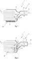
- FIG. 1 shows a schematic representation of a portion of a charge air cooler 1, which has a charge air distribution box 2 and outgoing of this charge air ducts 3 (of which only a few are exemplified here).
- the charge air distribution box 2 is supplied via a charge air line 4 charge air, wherein an inflow of the Charge air is indicated by the arrow 5.
- the charge air line 4 opens at an outlet opening 6 in the charge air distribution box 2 a.
- the charge air line 4 is associated with a charge air inlet 7 of the charge air cooler 1.
- the charge air flowing into the charge air distribution box 2 enters into the charge air ducts 3 or at least part of the charge air ducts 3 and flows through them.
- the charge air entering into the charge air distribution box 2 is preferably divided into the charge air ducts 3 lying in the direction of flow, that is, in the direction of the arrow 5, while off-set charge air ducts 3 are not or at most slightly charged with charge air. Because the charge air is cooled in the charge air cooler 1, in this case, if the cooling takes place below the dew point, water can condense and subsequently be present in the charge air cooler 1 in the form of condensate 8.
- the condensate 8 preferably collects in a geodetically lowermost of the charge air ducts 3, as indicated here. At the same time, however, due to its distance from the mouth opening 6, it is no longer sufficiently permeated by charge air in order to remove the condensate. This is indicated by the arrows 9. Rather, it becomes clear that it is even the formation of Return flow can come, which largely prevents the entry of the charge air into the condensate 8 having the charge air ducts 3.
- the area in which the condensate 8 accumulates may be referred to as condensate collection volume 10.
- the intercooler 1 in his in the FIG. 2 shown second embodiment associated with at least one flow guide 11.
- a plurality of flow guide elements 11 are provided, which are spaced from each other.
- the flow guide element is preferably present in the charge air distribution box 2.
- the flow guide 11 is oriented such that the charge air flowing in through the charge air inlet 7 is deflected in the direction of the condensate collection volume 10 at least in an operating state of the internal combustion engine. This is, as already explained above, in the at least one geodetically lowest of the charge air ducts 3 before.
- the deflection of the charge air through the flow guide 11 preferably follows from here merely indicated flow plane 12, which receives the direction indicated by the arrow 5 inflow in itself and is also perpendicular to a longitudinal center plane of the charge air level 3.
- the flow guide 11 deflects the charge air in the direction of the geodetically lowest of the charge air ducts 3.
- the condensate 8 is reliably removed from the condensate collection volume 10 and taken in the direction of the internal combustion engine in this way. Even with a sudden increase in the charge air mass flow, it can therefore not come to an abrupt increase in entrained by the charge air condensate. Accordingly, a negative influence on the operation of the internal combustion engine is reliably prevented.
Landscapes
- Engineering & Computer Science (AREA)
- Physics & Mathematics (AREA)
- Thermal Sciences (AREA)
- Mechanical Engineering (AREA)
- General Engineering & Computer Science (AREA)
- Chemical & Material Sciences (AREA)
- Combustion & Propulsion (AREA)
- Supercharger (AREA)
Abstract
Description
- Die Erfindung betrifft einen Ladeluftkühler für eine Brennkraftmaschine, mit einem Ladelufteinlass und einem Ladeluftauslass, die über mehrere strömungstechnisch parallel zueinander vorliegende, von einem Kühlmittel anströmbare Ladeluftkanäle strömungstechnisch miteinander verbunden sind. Die Erfindung betrifft weiterhin ein Verfahren zum Betreiben eines Ladeluftkühlers für eine Brennkraftmaschine.
- Der Ladeluftkühler ist der Brennkraftmaschine zugeordnet, welche beispielsweise dem Antreiben eines Kraftfahrzeugs, insoweit also dem Bereitstellen eines auf das Antreiben des Kraftfahrzeugs gerichteten Drehmoments dient. Die Brennkraftmaschine ist aufgeladen. Das bedeutet, dass ihr ein Verdichter zugeordnet ist, welcher der Brennkraftmaschine zugeführtes beziehungsweise zuzuführendes Frischgas stromaufwärts der Brennkraftmaschine verdichtet, also auf ein höheres Druckniveau bringt. Das Frischgas ist beispielsweise Frischluft oder zumindest zeitweise ein Frischluft-Abgas-Gemisch, falls die Brennkraftmaschine über eine externe Abgasrückführung verfügt. Die Aufladung bewirkt eine höhere Leistung und/oder eine höhere Effizienz der Brennkraftmaschine. Der Verdichter ist beispielsweise Bestandteil eines Laders, insbesondere eines Abgasturboladers oder eines elektrisch unterstützten Abgasturboladers, oder eines Kompressors. Der Verdichter kann auch als elektrisch angetriebener Verdichter vorliegen.
- Durch das Verdichten des Frischgases mittels des Verdichters steigt die Temperatur des Frischgases aufgrund des höheren Drucks und der verrichteten Kompressionsarbeit deutlich an. Weil entsprechend die Dichte des Frischgases abnimmt, führt die Temperaturzunahme des Frischgases zu einer Verringerung der Leistungs- und/oder Effizienzerhöhung. Aus diesem Grund ist strömungstechnisch zwischen dem Verdichter und der Brennkraftmaschine der Ladeluftkühler vorgesehen. Diesem wird das mittels des Verdichters verdichtete Frischgas, nachfolgend auch als Ladeluft bezeichnet, durch den Ladelufteinlass zugeführt. Anschließend durchströmt die Ladeluft die strömungstechnisch parallel zueinander angeordneten Ladeluftkanäle, um anschließend durch den Ladeluftauslass aus dem Ladeluftkühler auszuströmen. Nachfolgend wird die Ladeluft beziehungsweise das verdichtete Frischgas der Brennkraftmaschine zugeführt.
- Entsprechend ist der Ladelufteinlass strömungstechnisch gesehen auf der dem Verdichter zugewandten Seite des Ladeluftkühlers und der Ladeluftauslass auf der der Brennkraftmaschine zugewandten Seite angeordnet. Über die Ladeluftkanäle ist der Ladeluftauslass strömungstechnisch mit dem Ladelufteinlass verbunden, insbesondere ausschließlich. Die Ladeluftkanäle sind vorzugsweise parallel zueinander angeordnet, beispielsweise verlaufen also ihre Längsmittelachsen parallel zueinander. Bevorzugt sind die Ladeluftkanäle beabstandet voneinander, insbesondere parallel beabstandet voneinander, angeordnet, sodass zwischen ihnen Kühlmittel hindurchströmen kann. Das Kühlmittel dient dem Abführen von Wärme der Ladeluft. Entsprechend weist das Kühlmittel bevorzugt eine niedrigere Temperatur auf als die die Ladeluftkanäle durchströmende Ladeluft.
- In der Ladeluft ist üblicherweise ein gewisser Wasseranteil enthalten. Wird die Ladeluft in den Ladeluftkanälen stark abgekühlt, insbesondere bis unter ihren Taupunkt, so fällt dieses Wasser als Kondensat aus der Ladeluft aus. Bei einem großen Ladeluftmassenstrom durch den Ladeluftkühler wird das Kondensat zum größten Teil unverzüglich von der Ladeluft mitgenommen und gemeinsam mit dieser der Brennkraftmaschine zugeführt. Der der Brennkraftmaschine zugeführte Massenstrom an Kondensat beziehungsweise flüssigem Wasser ist dabei derart gering, dass keine Nachteile zu erwarten ist.
- Ist jedoch der Abgasmassenstrom gering, beispielsweise in einem Teillastbereich der Brennkraftmaschine, so kann sich das anfallende Kondensat in dem Ladeluftkühler, insbesondere in den Ladeluftkanälen, ansammeln. Bei einem nachfolgenden Anstieg des Ladeluftmassenstroms können nun große Mengen an Kondensat von der Ladeluft mitgenommen werden und in die Brennkraftmaschine gelangen. Weil dies zu verbrennungstechnischen Nachteilen in der Brennkraftmaschine führen kann, können Mittel vorgesehen sein, um das flüssige Wasser aus dem Ladeluftkühler abzuführen. Diese sind jedoch häufig konstruktiv sehr aufwändig und kostenträchtig.
- Es ist daher Aufgabe der Erfindung, einen Ladeluftkühler für eine Brennkraftmaschine vorzuschlagen, welcher gegenüber bekannten Ladeluftkühlern Vorteile aufweist, insbesondere ein Ansammeln von Kondensat in dem Ladeluftkühler zuverlässig verhindert.
- Dies wird mit einem Ladeluftkühler mit den Merkmalen des Anspruchs 1 erreicht. Dabei ist vorgesehen, dass der Ladeluftkühler wenigstens ein stromaufwärts der Ladeluftkanäle angeordnetes Strömungsleitelement aufweist, das durch den Ladelufteinlass eintretende Ladeluft zumindest in einem Betriebszustand der Brennkraftmaschine in Richtung eines Kondensatsammelvolumens des Ladeluftkühlers umlenkt.
- Das Luftleitelement ist also beispielsweise dem Ladelufteinlass zugeordnet und dient der Umlenkung der durch den Ladelufteinlass einströmenden und/oder in Richtung der Ladeluftkanäle strömenden Ladeluft. Die Umlenkung der Ladeluft durch das Strömungsleitelement erfolgt dabei derart, dass sie in Richtung des Kondensatsammelvolumens des Ladeluftkühlers strömt. Das Kondensatsammelvolumen wird beispielsweise von wenigstens einem der Ladeluftkanäle, insbesondere einem geodätisch gesehen am niedrigsten liegenden der Ladeluftkanäle gebildet. In diesen wird das anfallende Kondensat aufgrund des Schwerkrafteinflusses gedrängt.
- Das Umlenken der Ladeluft mithilfe des Strömungsleitelements ist zumindest in dem wenigstens einen Betriebszustand der Brennkraftmaschine vorgesehen. Bevorzugt ist das Strömungsleitelement dabei derart angeordnet, dass es auch bei kleinen Ladeluftmassenströmen für ein Einströmen der Ladeluft in das Kondensatsammelvolumen, also insbesondere in den das Kondensatsammelvolumen aufweisenden Ladeluftkanal beziehungsweise die das Kondensatsammelvolumen aufweisenden Ladeluftkanäle, sorgt. Auf diese Art und Weise wird auch bei kleinen Ladeluftmassenströmen verhindert, dass sich das Kondensat in dem Ladeluftkühler, insbesondere in dem Kondensatsammelvolumen ansammelt. Auch bei einer plötzlichen Erhöhung des Ladeluftmassenstroms kann es somit nicht zu einem abrupten Anstieg der der Brennkraftmaschine zugeführten Kondensatmenge kommen, sodass die verbrennungstechnischen Nachteile vermieden werden.
- Das Strömungsleitelement wird bevorzugt unmittelbar von der durch den Ladelufteinlass eintretenden Ladeluft angeströmt. Vorzugsweise liegt es strömungstechnisch zwischen dem Ladelufteinlass und einem dem Ladelufteinlass am nächsten liegenden der Ladeluftkanäle vor. Ohne das Strömungsleitelement würde die Ladeluft bevorzugt in diesen, dem Ladelufteinlass am nächsten liegenden Ladeluftkanal einströmen. Das Strömungsleitelement lenkt die Ladeluft jedoch von diesem fort, sodass sie in Richtung eines weiter von dem Ladelufteinlass angeordnet der Ladeluftkanäle strömt, insbesondere in diesen einströmt. Dieser Ladeluftkanal weist bevorzugt das Kondensatsammelvolumen wenigstens teilweise auf.
- Eine weitere Ausgestaltung der Erfindung sieht eine Ausgestaltung des Ladeluftkühlers als direkter Ladeluftkühler, wobei das Kühlmittel Umgebungsluft ist, oder als indirekter Ladeluftkühler, wobei das Kühlmittel ein Kühlfluid, insbesondere ein Kältemittel ist, vor. Die direkte Ladeluftkühlung ist derart angeordnet, dass er unmittelbar von Umgebungsluft durchströmt werden kann. Die Umgebungsluft soll also beispielsweise aufgrund eines geschwindigkeitsinduzierten Umgebungsluftstroms die Ladeluftkanäle anströmen und/oder umströmen beziehungsweise zwischen ihnen hindurchströmen.
- Alternativ kann der Ladeluftkühler selbstverständlich als indirekter Ladeluftkühler ausgestaltet sein. In diesem Fall ist er nicht unmittelbar dem geschwindigkeitsinduzierten Umgebungsluftstrom ausgesetzt. Vielmehr wird dem Ladeluftkühler das Kühlfluid zugeführt, welches zumindest zeitweise flüssig sein kann und vorzugsweise in einem Kühlkreislauf, insbesondere einem Kühlkreislauf der Brennkraftmaschine, umgewälzt wird. Das Kühlfluid kann in Form eines Kältemittels vorliegen.
- Eine weitere Ausgestaltung der Erfindung sieht vor, dass das Kondensatsammelvolumen in wenigstens einem geodätisch zuunterst liegenden der Ladeluftkanäle vorliegt. Wie bereits vorstehend erläutert, wird das in dem Ladeluftkühler anfallende Kondensat durch Schwerkrafteinfluss geodätisch gesehen nach unten gedrängt. Entsprechend sammelt es sich zunächst in dem in Einbaulage zuunterst liegenden der Ladeluftkanäle. Selbstverständlich kann sich ein Teil des Kondensats jedoch auch in mehreren der Ladeluftkanäle ansammeln, insbesondere den geodätisch zuunterst liegenden Ladeluftkanälen des Ladeluftkühlers.
- Im Rahmen einer weiteren Ausgestaltung der Erfindung kann vorgesehen sein, dass strömungstechnisch zwischen dem Ladelufteinlass und den Ladeluftkanälen ein Ladeluftverteilkasten vorliegt, in dem das Strömungsleitelement angeordnet ist. Der Ladelufteinlass ist beispielsweise eine Mündungsöffnung einer Ladeluftleitung in den Ladeluftverteilkasten, wobei über die Ladeluftleitung dem Ladeluftkühler die Ladeluft zugeführt wird. In Richtung der größten Erstreckung der Gesamtheit der Ladeluftkanäle des Ladeluftkühlers weist üblicherweise die Ladeluftleitung beziehungsweise ihre Mündungsöffnung kleinere Abmessungen auf als die Ladeluftkanäle.
- Entsprechend ist es notwendig, die Ladeluft aufzufächern, sodass sie den Ladeluftkanälen zugeführt werden kann. Zu diesem Zweck ist der Ladeluftverteilkasten vorgesehen, in welchen einerseits die Ladeluftleitung einmündet und von welchem andererseits die Ladeluftkanäle ausgehen. Der Ladeluftverteilkasten arbeitet insoweit nach Art eines Diffusors. Beispielsweise mündet die Ladeluftleitung geodätisch gesehen in etwa mittig in den Ladeluftverteilkasten ein. Auf der dem Ladeluftverteilkasten gegenüberliegenden Seite der Ladeluftkanäle können diese in einen Ladeluftsammelkasten einmünden. Diesem ist der Ladeluftauslass zugeordnet. In dem Ladeluftsammelkasten wird insoweit die die Ladeluftkanäle durchströmende Ladeluft zusammengeführt und anschließend gemeinsam in Richtung der Brennkraftmaschine abgeführt.
- Das Strömungsleitelement ist bevorzugt in dem Ladeluftverteilkasten angeordnet, insbesondere im Bereich der Mündungsöffnung. Entsprechend wird das Strömungsleitelement unmittelbar von der in den Ladeluftverteilkasten einströmenden Ladeluft angeströmt, nicht etwa erst nach eine Umlenkung durch den Ladeluftverteilkasten beziehungsweise einer Wand des Ladeluftverteilkastens. Das Strömungsleitelement liegt in dem Ladeluftverteilkasten vor, insbesondere geht es von der Wand des Ladeluftverteilkastens vor. Dabei ist es vorzugsweise an der Wand befestigt oder gelagert. Insbesondere erstreckt sich das Strömungsleitelement in wenigstens einer Richtung durch den gesamten Ladeluftverteilkasten, also von einer Wand zu einer gegenüberliegenden Wand des Ladeluftverteilkastens. Es kann jedoch auch vorgesehen sein, dass das Strömungsleitelement den Ladeluftverteilkasten nur teilweise durchgreift, also nur einen Teil des Abstands zwischen den gegenüberliegenden Wänden überbrückt. Dieser Teil entspricht bezogen auf den Abstand zwischen den Wänden beispielsweise mindestens 25 %, mindestens 50 %, mindestens 75 %, mindestens 90 % oder mindestens 95 %.
- Eine Weiterbildung der Erfindung sieht vor, dass die Ladeluft in den Ladeluftverteilkasten durch den Ladelufteinlass mit einer Einströmrichtung einströmt, die in einer senkrecht auf einer Längsmittelebene der Ladeluftkanäle stehenden Strömungsebene liegt, wobei das Strömungsleitelement die Ladeluft derart umlenkt, dass sie von der Strömungsebene fortströmt. Die Längsmittelebene der Ladeluftkanäle ist eine Ebene, die die Längsmittelachsen mehrerer der Ladeluftkanäle, insbesondere aller Ladeluftkanäle des Ladeluftkühlers, in sich aufnimmt. Entsprechend erstreckt sie sich zum Beispiel in geodätisch senkrechter Richtung oder schließt mit dieser einen geringen Winkel von höchstens 15 °, höchstens 10 ° oder höchstens 5° ein.
- Die Strömungsebene steht senkrecht auf dieser Längsmittelebene und nimmt gleichzeitig die Einströmrichtung der Ladeluft in den Ladeluftverteilkasten in sich auf. Die Einströmrichtung bezeichnet dabei bevorzugt die Hauptströmungsrichtung der in den Ladeluftverteilkasten eintretenden Ladeluft. Das Strömungsleitelement ist derart in dem Ladeluftstrom angeordnet, dass diese in eine von der Strömungsebene abgewandte Richtung umgelenkt wird. Das Umlenken erfolgt dabei bevorzugt in Richtung einer geodätisch unten liegenden Seite der Strömungsebene.
- Im Rahmen einer weiteren Ausgestaltung der Erfindung kann vorgesehen sein, dass das Strömungsleitelement ein Strömungsprofil aufweist. Beispielsweise ist das Strömungsleitelement also tragflächenartig. Mit einer derartigen Ausgestaltung des Strömungsleitelements kann eine Beschleunigung der umgelenkten Ladeluft erzielt werden. Aufgrund der höheren Geschwindigkeit kann die Ladeluft einen größeren Anteil des in dem Kondensatsammelvolumen vorliegenden Kondensats in Richtung der Brennkraftmaschine mitnehmen. Dies gilt insbesondere, falls mehrere Strömungsleitelemente vorliegen, welche vorzugsweise beabstandet voneinander in dem Ladeluftverteilkasten angeordnet sind.
- Schließlich kann in einer weiteren Ausgestaltung der Erfindung vorgesehen sein, dass das Strömungsleitelement verstellbar ist. Dem Strömungsleitelement ist insoweit eine Stellvorrichtung zugeordnet, mittels welchem beispielsweise ein Anstellwinkel des Strömungsleitelements einstellbar ist. Der Anstellwinkel kann dabei in Abhängigkeit von dem Betriebszustand der Brennkraftmaschine, insbesondere in Abhängigkeit von einem Ladeluftmassenstrom, ausgewählt und eingestellt werden. Durch die Verstellbarkeit des Strömungsleitelements kann beispielsweise in einem Teillastbereich der Brennkraftmaschine, also bei einem geringeren Ladeluftmassenstrom, eine stärkere Umlenkung der Ladeluft realisiert werden als bei Volllast, für welche ein größerer Ladeluftmassenstrom vorliegt.
- In letzterem Fall wird das Kondensat auch ohne die Umlenkung der Ladeluft durch das Strömungsleitelement in ausreichender Menge aus dem Ladeluftkühler abgeführt. Gleichzeitig wird durch die geringere Umlenkung der Druckverlust des Ladeluftkühlers für die Ladeluft verringert. Besonders bevorzugt liegt in wenigstens einem Betriebszustand der Brennkraftmaschine, beispielsweise bei Volllast, überhaupt keine Umlenkung der Ladeluft durch das Strömungsleitelement vor oder zumindest lediglich eine Umlenkung, die einer mittels des Strömungsleitelements minimal einstallbaren Umlenkung entspricht.
- Im Rahmen einer besonders bevorzugten Vorgehensweise wird das verstellbare Strömungsleitelement dazu verwendet, die Ladeluft periodisch unterschiedlichen Ladeluftkanälen zuzuführen. Beispielsweise wird hierzu eine Reihenfolge vorgegeben, in Richtung welchen Ladeluftkanals die Ladeluft mittels des Strömungsleitelements umgelenkt werden soll. Die Ladeluftkanäle, in deren Richtung die Ladeluft umgelenkt werden soll, bilden bevorzugt eine Untermenge aller Ladeluftkanäle des Ladeluftkühlers. Diese Untermenge kann nur einen Teil der Ladeluftkanäle, aber auch alle Ladeluftkanäle umfassen. Ist nur ein Teil umfasst, so enthält die Untermenge mehrere bevorzugt in geodätischer Richtung weiter unten liegende Ladeluftkanäle, insbesondere mehrere in dieser Richtung am tiefsten liegende Ladeluftkanäle.
- Das Strömungsleitelement wird nun dazu verwendet, die Ladeluft periodisch jeweils in Richtung eines in der Untermenge enthaltenen Ladeluftkanals umzulenken, sodass dieser hauptsächlich mit der Ladeluft beaufschlagt wird. Beispielsweise wird in bestimmten Zeitabständen auf einen anderen Ladeluftkanal der Untermenge umgeschaltet, sodass innerhalb eines Entwässerungszyklusses die Ladeluft jeweils in Richtung jedes in der Untermenge enthaltenen Ladeluftkanals umgelenkt wird. Somit wird in dem Entwässerungszyklus jeder in der Untermenge enthaltene Ladeluftkanal zumindest einmalig hauptsächlich mit der Ladeluft beaufschlagt beziehungsweise die Ladeluft in seine Richtung umgelenkt. Entsprechend wird das Kondensat besonders effektiv aus ihm ausgetragen. Zudem kann in dem jeweiligen Ladeluftkanal bereits die Bildung des Kondensats verhindert werden.
- Bei einer derartigen Vorgehensweise wird das Strömungsleitelement periodisch verstellt, sodass die Ladeluft in Richtung unterschiedlicher Ladeluftkanäle umgelenkt wird. Während des Entwässerungszyklusses überstreicht also die Ladeluft durch das Verstellen des Strömungsleitelements mehrere der Ladeluftkanäle, insbesondere alle Ladeluftkanäle. Das periodische Verstellen kann permanent durchgeführt werden oder in Abhängigkeit von wenigstens einer Umgebungsbedingung und/oder dem Betriebszustand der Brennkraftmaschine. Als Umgebungsbedingung kommt beispielsweise eine Umgebungstemperatur zum Einsatz. Insbesondere wird das Verstellen nur bei Unterschreiten eines Temperaturschwellenwerts durch die Umgebungstemperatur vorgenommen. Alternativ oder zusätzlich wird das Verstellen nur durchgeführt, wenn ein bestimmter Betriebszustand der Brennkraftmaschine vorliegt, diese insbesondere bei Teillast betrieben wird. Bei Volllast und/oder bei Überschreiten des Temperaturschwellwerts dagegen kann das Strömungsleitelement derart eingestellt werden, dass ein möglichst geringer Druckverlust beziehungsweise Strömungswiderstand vorliegt, also insbesondere so, dass die Ladeluft nicht umgelenkt wird oder zumindest die minimal einstallbare Umlenkung vorliegt.
- Die Erfindung betrifft weiterhin ein Verfahren zum Betreiben eines Ladeluftkühlers für eine Brennkraftmaschine, insbesondere eines Ladeluftkühlers gemäß den vorstehenden Ausführungen, wobei der Ladeluftkühler einen Ladelufteinlass und einen Ladeluftauslass aufweist, die über mehrere strömungstechnisch parallel zueinander vorliegende, von einem Kühlmittel anströmbare Ladeluftkanäle strömungstechnisch miteinander verbunden sind. Dabei ist vorgesehen, dass der Ladeluftkühler wenigstens ein stromaufwärts der Ladeluftkanäle angeordnetes Strömungsleitelement aufweist, das durch den Ladelufteinlass eintretende Ladeluft zumindest in einem Betriebszustand der Brennkraftmaschine in Richtung eines Kondensatsammelvolumens des Ladeluftkühlers umlenkt.
- Auf die Vorteile einer derartigen Vorgehensweise beziehungsweise einer derartigen Ausgestaltung des Ladeluftkühlers wurde bereits hingewiesen. Sowohl das Verfahren als auch der Ladeluftkühler können gemäß den vorstehenden Ausführungen weitergebildet sein, sodass insoweit auf diese verwiesen wird.
- Im Rahmen einer weiteren Ausgestaltung der Erfindung kann vorgesehen sein, dass das Strömungsleitelement verstellbar ist und ein Anstellwinkel des Strömungsleitelements in Abhängigkeit von dem Betriebszustand ausgewählt und eingestellt wird. Hierauf wurde vorstehend bereits hingewiesen. Beispielsweise wird in Abhängigkeit von wenigstens einer Betriebsgröße der Brennkraftmaschine der Anstellwinkel bestimmt, insbesondere berechnet. Als Betriebsgröße kann beispielsweise das Drehmoment, die Drehzahl der Brennkraftmaschine oder der Ladeluftmassenstrom verwendet werden. Die Bestimmung des Anstellwinkels erfolgt anhand genau einer der genannten Betriebsgrößen oder mehrerer der Betriebsgrößen, insbesondere aller genannten Betriebsgrößen.
- Schließlich ist in einer weiteren bevorzugten Ausführungsform der Erfindung vorgesehen, dass das Strömungsleitelement derart eingestellt wird, dass die Ladeluft umso stärker umgelenkt wird, je kleiner ein den Ladeluftkühler durchströmender Ladeluftmassenstrom ist, und/oder umso stärker umgelenkt wird, je größer der Ladeluftmassenstrom ist. Besonders bevorzugt erfolgt ab dem Überschreiten eines Ladeluftmassenstromgrenzwerts durch den Ladeluftmassenstrom keine Umlenkung der Ladeluft durch das Strömungsleitelement.
- Ist der Ladeluftmassenstrom jedoch kleiner als der Ladeluftmassenstromgrenzwert, so kann die Umlenkung umso stärker eingestellt werden, je geringer der Ladeluftmassenstrom ist. Auf diese Weise wird sichergestellt, dass einerseits bei einem geringeren Ladeluftmassenstrom das Kondensat zuverlässig aus dem Ladeluftkühler abgeführt und andererseits bei einem größeren Ladeluftmassenstrom ein geringer Druckverlust des Ladeluftkühlers sichergestellt wird.
- Die Erfindung wird nachfolgend anhand der in der Zeichnung dargestellten Ausführungsbeispiele näher erläutert, ohne dass eine Beschränkung der Erfindung erfolgt. Dabei zeigt:
- Figur 1
- eine schematische Schnittdarstellung eines Ladeluftkühlers für eine Brennkraftmaschine in einer ersten Ausführungsform, sowie
- Figur 2
- eine schematische Schnittdarstellung des Ladeluftkühlers in einer zweiten Ausführungsform.
- Die
Figur 1 zeigt eine schematische Darstellung eines Bereichs eines Ladeluftkühlers 1, der einen Ladeluftverteilkasten 2 sowie von diesem ausgehende Ladeluftkanäle 3 (von welchen hier lediglich einige beispielhaft gekennzeichnet sind) aufweist. Dem Ladeluftverteilkasten 2 wird über eine Ladeluftleitung 4 Ladeluft zugeführt, wobei eine Einströmrichtung der Ladeluft durch den Pfeil 5 angedeutet ist. Die Ladeluftleitung 4 mündet an einer Mündungsöffnung 6 in den Ladeluftverteilkasten 2 ein. - Es wird deutlich, dass sich stromabwärts der Mündungsöffnung 6 der Durchströmungsquerschnitt aufweitet, weil die Ladeluftkanäle 3 in ihrer Gesamtheit in wenigstens einer Richtung größere Abmessungen aufweisen als die Ladeluftleitung 4 beziehungsweise die Mündungsöffnung 6. Die Ladeluftleitung 4 ist einem Ladelufteinlass 7 des Ladeluftkühlers 1 zugeordnet. Die in den Ladeluftverteilkasten 2 einströmende Ladeluft tritt in die Ladeluftkanäle 3 oder zumindest einen Teil der Ladeluftkanäle 3 ein und durchströmt diese. Auf der dem Ladeluftverteilkasten 2 abgewandten Seite der Ladeluftkanäle 3 sind diese bevorzugt an einen Ladeluftsammelkasten angeschlossen, welcher einem Ladeluftauslass (hier nicht dargestellt) des Ladeluftkühlers 1 zugeordnet ist.
- Insbesondere bei einem geringen Ladeluftmassenstrom kann es vorkommen, dass die in den Ladeluftverteilkasten 2 eintretende Ladeluft bevorzugt auf die in Strömungsrichtung, also in Richtung des Pfeils 5, liegenden Ladeluftkanäle 3 aufgeteilt wird, während abseits liegende Ladeluftkanäle 3 nicht oder allenfalls geringfügig mit Ladeluft beaufschlagt werden. Weil die Ladeluft in dem Ladeluftkühler 1 abgekühlt wird, kann in diesem, falls das Abkühlen bis unter den Taupunkt erfolgt, Wasser kondensieren und nachfolgend in Form von Kondensat 8 in dem Ladeluftkühler 1 vorliegen.
- Aufgrund des Schwerkrafteinflusses sammelt sich das Kondensat 8 bevorzugt in einem geodätisch zuunterst liegenden der Ladeluftkanäle 3, wie hier angedeutet ist. Gleichzeitig wird dieser aufgrund seines Abstands von der Mündungsöffnung 6 jedoch nicht mehr ausreichend von Ladeluft durchströmt, um das Kondensat abzuführen. Dies ist durch die Pfeile 9 angedeutet. Vielmehr wird deutlich, dass es sogar zur Bildung von Rückströmgebieten kommen kann, welche das Eintreten der Ladeluft in den das Kondensat 8 aufweisenden der Ladeluftkanäle 3 weitgehend verhindert. Der Bereich, in welchem sich das Kondensat 8 ansammelt, kann als Kondensatsammelvolumen 10 bezeichnet werden.
- Um auch bei niedrigen Ladeluftmassenströmen ein gleichmäßiges Abführen des Kondensats 8 aus dem Ladeluftkühler 1 zu ermöglichen, ist dem Ladeluftkühler 1 in seiner in der
Figur 2 dargestellten zweiten Ausführungsform wenigstens ein Strömungsleitelement 11 zugeordnet. In dem dargestellten Ausführungsbeispiel sind mehrere Strömungsleitelemente 11 vorgesehen, die beabstandet voneinander angeordnet sind. Das Strömungsleitelement liegt bevorzugt in dem Ladeluftverteilkasten 2 vor. Das Strömungsleitelement 11 ist derart ausgerichtet, dass die durch den Ladelufteinlass 7 einströmende Ladeluft zumindest in einem Betriebszustand der Brennkraftmaschine in Richtung des Kondensatsammelvolumens 10 umgelenkt wird. Dieses liegt, wie bereits vorstehend erläutert, in dem wenigstens einen geodätisch zuunterst liegenden der Ladeluftkanäle 3 vor. - Die Umlenkung der Ladeluft durch das Strömungsleitelement 11 folgt dabei bevorzugt fort von einer hier lediglich angedeuteten Strömungsebene 12, die die durch den Pfeil 5 angedeutete Einströmrichtung in sich aufnimmt und zudem senkrecht auf einer Längsmittelebene der Ladeluftebene 3 steht. Insbesondere lenkt das Strömungsleitelement 11 die Ladeluft in Richtung des geodätisch zuunterst liegenden der Ladeluftkanäle 3 um. Durch die Pfeile 9 wird deutlich, dass mithilfe des Strömungsleitelements 11 eine Vergleichmäßigung des Ladeluftmassenstroms durch die Ladeluftkanäle 3 erzielt werden kann oder dass sogar der größere Teil der Ladeluft durch die am weitesten unten liegenden der Ladeluftkanäle 3 strömt.
- Auch bei niedrigen Ladeluftmassenströmen wird auf diese Art und Weise das Kondensat 8 zuverlässig aus dem Kondensatsammelvolumen 10 abgeführt und in Richtung der Brennkraftmaschine mitgenommen. Auch bei einem plötzlichen Anstieg des Ladeluftmassenstroms kann es also nicht zu einem abrupten Anstieg der von der Ladeluft mitgenommenen Kondensatmenge kommen. Entsprechend wird ein negativer Einfluss auf den Betrieb der Brennkraftmaschine zuverlässig verhindert.
Claims (10)
- Ladeluftkühler (1) für eine Brennkraftmaschine, mit einem Ladelufteinlass (7) und einem Ladeluftauslass, die über mehrere strömungstechnisch parallel zueinander vorliegende, von einem Kühlmittel anströmbare Ladeluftkanäle (3) strömungstechnisch miteinander verbunden sind, dadurch gekennzeichnet, dass der Ladeluftkühler (1) wenigstens ein stromaufwärts der Ladeluftkanäle (3) angeordnetes Strömungsleitelement (11) aufweist, das durch den Ladelufteinlass (7) eintretende Ladeluft zumindest in einem Betriebszustand der Brennkraftmaschine in Richtung eines Kondensatsammelvolumens (10) des Ladeluftkühlers (1) umlenkt.
- Ladeluftkühler nach Anspruch 1, gekennzeichnet durch eine Ausgestaltung als direkter Ladeluftkühler (1), wobei das Kühlmittel Umgebungsluft ist, oder als indirekter Ladeluftkühler (1), wobei das Kühlmittel ein Kühlfluid, insbesondere ein Kältemittel, ist.
- Ladeluftkühler nach einem der vorhergehenden Ansprüche, dadurch gekennzeichnet, dass das Kondensatsammelvolumen (10) in wenigstens einem geodätisch zuunterst liegenden der Ladeluftkanäle (3) vorliegt.
- Ladeluftkühler nach einem der vorhergehenden Ansprüche, dadurch gekennzeichnet, dass strömungstechnisch zwischen dem Ladelufteinlass (7) und den Ladeluftkanälen (3) ein Ladeluftverteilkasten (2) vorliegt, in dem das Strömungsleitelement (11) angeordnet ist.
- Ladeluftkühler nach einem der vorhergehenden Ansprüche, dadurch gekennzeichnet, dass die Ladeluft in den Ladeluftverteilkasten (2) durch den Ladelufteinlass (7) mit einer Einströmrichtung (5) einströmt, die in einer senkrecht auf einer Längsmittelebene der Ladeluftkanäle (3) stehenden Strömungsebene (12) liegt, wobei das Strömungsleitelement (11) die Ladeluft derart umlenkt, dass sie von der Strömungsebene (12) fort strömt.
- Ladeluftkühler nach einem der vorhergehenden Ansprüche, dadurch gekennzeichnet, dass das Strömungsleitelement (11) ein Strömungsprofil aufweist.
- Ladeluftkühler nach einem der vorhergehenden Ansprüche, dadurch gekennzeichnet, dass das Strömungsleitelement (11) verstellbar ist.
- Verfahren zum Betreiben eines Ladeluftkühlers (1) für eine Brennkraftmaschine, insbesondere eines Ladeluftkühlers (1) nach einem oder mehreren der vorhergehenden Ansprüche, wobei der Ladeluftkühler (1) einen Ladelufteinlass (7) und einen Ladeluftauslass aufweist, die über mehrere strömungstechnisch parallel zueinander vorliegende, von einem Kühlmittel anströmbare Ladeluftkanäle (3) strömungstechnisch miteinander verbunden sind, dadurch gekennzeichnet, dass der Ladeluftkühler (1) wenigstens ein stromaufwärts der Ladeluftkanäle (3) angeordnetes Strömungsleitelement (11) aufweist, das durch den Ladelufteinlass (7) eintretende Ladeluft zumindest in einem Betriebszustand der Brennkraftmaschine in Richtung eines Kondensatsammelvolumens (10) des Ladeluftkühlers (1) umlenkt.
- Verfahren nach Anspruch 8, dadurch gekennzeichnet, dass das Strömungsleitelement (11) verstellbar ist und ein Anstellwinkel des Strömungsleitelements (11) in Abhängigkeit von dem Betriebszustand ausgewählt und eingestellt wird.
- Verfahren nach einem der vorhergehenden Ansprüche, dadurch gekennzeichnet, dass das Strömungsleitelement (11) derart eingestellt wird, dass die Ladeluft umso stärker umgelenkt wird, je kleiner ein den Ladeluftkühler (1) durchströmender Ladeluftmassenstrom ist, und/oder umso stärker umgelenkt wird, je größer der Ladeluftmassenstrom ist.
Applications Claiming Priority (1)
| Application Number | Priority Date | Filing Date | Title |
|---|---|---|---|
| DE102015016812.6A DE102015016812A1 (de) | 2015-12-23 | 2015-12-23 | Ladeluftkühler für eine Brennkraftmaschine sowie Verfahren zum Betreiben eines Ladeluftkühlers |
Publications (1)
| Publication Number | Publication Date |
|---|---|
| EP3184776A1 true EP3184776A1 (de) | 2017-06-28 |
Family
ID=57406084
Family Applications (1)
| Application Number | Title | Priority Date | Filing Date |
|---|---|---|---|
| EP16200495.6A Withdrawn EP3184776A1 (de) | 2015-12-23 | 2016-11-24 | Ladeluftkühler für eine brennkraftmaschine sowie verfahren zum betreiben eines ladeluftkühlers |
Country Status (4)
| Country | Link |
|---|---|
| US (1) | US20170184011A1 (de) |
| EP (1) | EP3184776A1 (de) |
| CN (1) | CN106907233A (de) |
| DE (1) | DE102015016812A1 (de) |
Cited By (5)
| Publication number | Priority date | Publication date | Assignee | Title |
|---|---|---|---|---|
| US20180231335A1 (en) * | 2017-02-16 | 2018-08-16 | Hs Marston Aerospace Limited | Flow guide for heat exchanger |
| WO2019063946A1 (fr) * | 2017-09-29 | 2019-04-04 | Valeo Systemes Thermiques | Dispositif de ventilation pour module d'echange de chaleur de vehicule automobile a guides d'air du flux d'air traversant les collecteurs d'air |
| FR3071873A1 (fr) * | 2017-09-29 | 2019-04-05 | Valeo Systemes Thermiques | Dispositif de ventilation a tubes pour module d’echange de chaleur de vehicule automobile a cloisons de repartition du flux d’air dans les collecteurs d’air |
| FR3071875A1 (fr) * | 2017-09-29 | 2019-04-05 | Valeo Systemes Thermiques | Dispositif de ventilation a tubes pour module d'echange de chaleur de vehicule automobile a deflecteurs du flux d'air dans les collecteurs d'air |
| CN109780894A (zh) * | 2018-12-27 | 2019-05-21 | 中国寰球工程有限公司 | 立式管壳式挠性管板换热器 |
Citations (6)
| Publication number | Priority date | Publication date | Assignee | Title |
|---|---|---|---|---|
| JPS6118394U (ja) * | 1984-06-30 | 1986-02-03 | カルソニックカンセイ株式会社 | 熱交換器 |
| EP2256450A2 (de) * | 2009-05-28 | 2010-12-01 | Behr GmbH & Co. KG | Wärmeübertrager |
| WO2011102784A1 (en) * | 2010-02-19 | 2011-08-25 | Scania Cv Ab | Arrangement for preventing ice formation in a charge air cooler |
| DE102013107925A1 (de) * | 2012-07-26 | 2014-01-30 | Ford Global Technologies, Llc | Ladeluftkühler-Steuersystem und Verfahren |
| US20140100074A1 (en) * | 2012-10-10 | 2014-04-10 | Ford Global Technologies, Llc | Charge air cooler condensate purging cycle |
| DE202014101948U1 (de) * | 2013-05-02 | 2014-07-16 | Ford Global Technologies, Llc | Variables Ventilsystem,um die Kondensation in einem Ladeluftkühler zu verrringern |
Family Cites Families (6)
| Publication number | Priority date | Publication date | Assignee | Title |
|---|---|---|---|---|
| DE19910651A1 (de) * | 1998-03-13 | 1999-09-16 | Denso Corp | Motorkühlvorrichtung |
| DE102008032388B4 (de) * | 2008-07-09 | 2011-07-07 | Audi Ag, 85057 | Ladeluftkühler |
| DE102011078454B4 (de) * | 2011-06-30 | 2013-05-08 | Ford Global Technologies, Llc | Brennkraftmaschine mit Ladeluftkühlung |
| US9506430B2 (en) * | 2012-12-05 | 2016-11-29 | Ford Global Technologies, Llc | Charge air cooler component diagnostics |
| DE102013006956B4 (de) * | 2013-04-23 | 2020-06-04 | Mann+Hummel Gmbh | Luftführendes Bauteil mit einem Ladeluftkühler |
| WO2015163181A1 (ja) * | 2014-04-25 | 2015-10-29 | 日立オートモティブシステムズ株式会社 | 冷却制御装置、流量制御弁及び冷却制御方法 |
-
2015
- 2015-12-23 DE DE102015016812.6A patent/DE102015016812A1/de not_active Withdrawn
-
2016
- 2016-11-24 EP EP16200495.6A patent/EP3184776A1/de not_active Withdrawn
- 2016-12-22 US US15/388,690 patent/US20170184011A1/en not_active Abandoned
- 2016-12-22 CN CN201611199191.4A patent/CN106907233A/zh active Pending
Patent Citations (6)
| Publication number | Priority date | Publication date | Assignee | Title |
|---|---|---|---|---|
| JPS6118394U (ja) * | 1984-06-30 | 1986-02-03 | カルソニックカンセイ株式会社 | 熱交換器 |
| EP2256450A2 (de) * | 2009-05-28 | 2010-12-01 | Behr GmbH & Co. KG | Wärmeübertrager |
| WO2011102784A1 (en) * | 2010-02-19 | 2011-08-25 | Scania Cv Ab | Arrangement for preventing ice formation in a charge air cooler |
| DE102013107925A1 (de) * | 2012-07-26 | 2014-01-30 | Ford Global Technologies, Llc | Ladeluftkühler-Steuersystem und Verfahren |
| US20140100074A1 (en) * | 2012-10-10 | 2014-04-10 | Ford Global Technologies, Llc | Charge air cooler condensate purging cycle |
| DE202014101948U1 (de) * | 2013-05-02 | 2014-07-16 | Ford Global Technologies, Llc | Variables Ventilsystem,um die Kondensation in einem Ladeluftkühler zu verrringern |
Cited By (6)
| Publication number | Priority date | Publication date | Assignee | Title |
|---|---|---|---|---|
| US20180231335A1 (en) * | 2017-02-16 | 2018-08-16 | Hs Marston Aerospace Limited | Flow guide for heat exchanger |
| WO2019063946A1 (fr) * | 2017-09-29 | 2019-04-04 | Valeo Systemes Thermiques | Dispositif de ventilation pour module d'echange de chaleur de vehicule automobile a guides d'air du flux d'air traversant les collecteurs d'air |
| FR3071873A1 (fr) * | 2017-09-29 | 2019-04-05 | Valeo Systemes Thermiques | Dispositif de ventilation a tubes pour module d’echange de chaleur de vehicule automobile a cloisons de repartition du flux d’air dans les collecteurs d’air |
| FR3071875A1 (fr) * | 2017-09-29 | 2019-04-05 | Valeo Systemes Thermiques | Dispositif de ventilation a tubes pour module d'echange de chaleur de vehicule automobile a deflecteurs du flux d'air dans les collecteurs d'air |
| CN111630257A (zh) * | 2017-09-29 | 2020-09-04 | 法雷奥热系统公司 | 带有用于引导穿过空气歧管的空气流的空气引导件的机动车辆热交换模块的通风装置 |
| CN109780894A (zh) * | 2018-12-27 | 2019-05-21 | 中国寰球工程有限公司 | 立式管壳式挠性管板换热器 |
Also Published As
| Publication number | Publication date |
|---|---|
| DE102015016812A1 (de) | 2017-06-29 |
| US20170184011A1 (en) | 2017-06-29 |
| CN106907233A (zh) | 2017-06-30 |
Similar Documents
| Publication | Publication Date | Title |
|---|---|---|
| EP2129888B1 (de) | Ladefluidansaugmodul und verbrennungskraftmaschine | |
| DE102007028583A1 (de) | Luftbypasssystem für einen Gasturbineneinlass | |
| EP1496221A2 (de) | Vorrichtung zur Zuführung eines Gasgemisches zu Saugstutzen von Zylindern eines Verbrennungsmotors | |
| DE102015016812A1 (de) | Ladeluftkühler für eine Brennkraftmaschine sowie Verfahren zum Betreiben eines Ladeluftkühlers | |
| DE102019206448B4 (de) | Motorsystem | |
| DE102006048667A1 (de) | Wärmeübertrageranordnung und Verfahren zur Wärmeübertragung | |
| DE102013206690A1 (de) | Brennkraftmaschine mit Ladeluftkühler und Abgasrückführung und Verfahren zum Herstellen einer derartigen Brennkraftmaschine | |
| EP2995899A1 (de) | Wärmeübertrager | |
| DE102008022887A1 (de) | Kühlmodul, insbesondere eines Kraftfahrzeuges, mit wenigstens zwei Kühleinrichtungen, Kraftfahrzeug mit einer Brennkraftmaschine und Verfahren zum Kühlen einer ersten Kühleinrichtung und einer weiteren Kühleinrichtung | |
| DE102015004741A1 (de) | Antriebseinrichtung sowie Verfahren zum Betreiben einer Antriebseinrichtung | |
| EP1769147B1 (de) | Verfahren zum betrieb einer gasturbogruppe | |
| DE102019105033B4 (de) | System zur abgasrückführung | |
| DE102012216756B4 (de) | Abgasrückführungs-Kühlungsmodul, Abgasrückführungsanlage sowie Verfahren zum Betrieb einer Abgasrückführungsanlage | |
| DE102015208475B4 (de) | Einrichtung zum Abführen von Kondensat aus einer Turboladeranordnung | |
| DE102007054762A1 (de) | Kurbelgehäuseent- und -belüftungseinrichtung für eine Brennkraftmaschine | |
| DE102015117123A1 (de) | Ladeluftkühler für einen aufgeladenen Motor | |
| DE102014216101A1 (de) | Aufgeladene Brennkraftmaschine mit Abgasrückführung und Verfahren zum Betreiben einer derartigen Brennkraftmaschine | |
| DE202016104756U1 (de) | Abscheidevorrichtung, Entlüftungssystem für ein Kurbelgehäuse sowie Verbrennungsmotor mit einer derartigen Abscheidevorrichtung | |
| DE102011109264A1 (de) | Abgasrückführeinrichtung für eine Brennkraftmaschine eines Fahrzeuges sowie Verfahren zum Betreiben einer Abgasrückführeinrichtung | |
| DE102018221147B4 (de) | Aufgeladene Brennkraftmaschine mit Verdichter und stromaufwärts des Verdichters angeordneter Leiteinrichtung | |
| DE102018130829B4 (de) | Absperrorgan zur Flutenverbindung und Flutentrennung eines Turboladers sowie Verbrennungsmotor und Fahrzeug mit einem solchen | |
| DE102015012726A1 (de) | Turbine für einen Abgasturbolader | |
| WO2016020161A1 (de) | Kühler mit einem flüssigkeitsabscheider und einem bypass | |
| DE102016221004B4 (de) | Verbrennungskraftmaschinen Luftführung mit Ladeluftkühler | |
| DE102015208482B4 (de) | Einrichtung zum Abführen von Kondensat aus einer Turboladeranordnung |
Legal Events
| Date | Code | Title | Description |
|---|---|---|---|
| PUAI | Public reference made under article 153(3) epc to a published international application that has entered the european phase |
Free format text: ORIGINAL CODE: 0009012 |
|
| AK | Designated contracting states |
Kind code of ref document: A1 Designated state(s): AL AT BE BG CH CY CZ DE DK EE ES FI FR GB GR HR HU IE IS IT LI LT LU LV MC MK MT NL NO PL PT RO RS SE SI SK SM TR |
|
| AX | Request for extension of the european patent |
Extension state: BA ME |
|
| 17P | Request for examination filed |
Effective date: 20180102 |
|
| RBV | Designated contracting states (corrected) |
Designated state(s): AL AT BE BG CH CY CZ DE DK EE ES FI FR GB GR HR HU IE IS IT LI LT LU LV MC MK MT NL NO PL PT RO RS SE SI SK SM TR |
|
| 17Q | First examination report despatched |
Effective date: 20180315 |
|
| STAA | Information on the status of an ep patent application or granted ep patent |
Free format text: STATUS: THE APPLICATION HAS BEEN WITHDRAWN |
|
| 18W | Application withdrawn |
Effective date: 20180622 |