EP3184754B1 - Sensoranordnung und messverfahren für eine turbomaschine - Google Patents
Sensoranordnung und messverfahren für eine turbomaschine Download PDFInfo
- Publication number
- EP3184754B1 EP3184754B1 EP16205345.8A EP16205345A EP3184754B1 EP 3184754 B1 EP3184754 B1 EP 3184754B1 EP 16205345 A EP16205345 A EP 16205345A EP 3184754 B1 EP3184754 B1 EP 3184754B1
- Authority
- EP
- European Patent Office
- Prior art keywords
- sensor element
- seal
- flow
- fluid
- sensor
- Prior art date
- Legal status (The legal status is an assumption and is not a legal conclusion. Google has not performed a legal analysis and makes no representation as to the accuracy of the status listed.)
- Active
Links
- 238000000034 method Methods 0.000 title description 4
- 239000012530 fluid Substances 0.000 claims description 37
- 239000007789 gas Substances 0.000 claims description 20
- 238000005259 measurement Methods 0.000 claims description 8
- 238000007789 sealing Methods 0.000 claims description 4
- 239000000567 combustion gas Substances 0.000 claims description 3
- 239000000126 substance Substances 0.000 claims 2
- 238000000691 measurement method Methods 0.000 claims 1
- 230000003287 optical effect Effects 0.000 description 5
- 238000002485 combustion reaction Methods 0.000 description 4
- 238000001816 cooling Methods 0.000 description 3
- 0 C1*2C1CCC2 Chemical compound C1*2C1CCC2 0.000 description 2
- 238000001514 detection method Methods 0.000 description 2
- 238000012544 monitoring process Methods 0.000 description 2
- RJYUUVZJHIJJCR-UHFFFAOYSA-N C(C1)C1C1C(C2)CC2C1 Chemical compound C(C1)C1C1C(C2)CC2C1 RJYUUVZJHIJJCR-UHFFFAOYSA-N 0.000 description 1
- CFOHRCNONSEVOJ-UHFFFAOYSA-N CCC1CC=CCC1 Chemical compound CCC1CC=CCC1 CFOHRCNONSEVOJ-UHFFFAOYSA-N 0.000 description 1
- 206010053615 Thermal burn Diseases 0.000 description 1
- 241000510009 Varanus griseus Species 0.000 description 1
- 230000001154 acute effect Effects 0.000 description 1
- 230000008033 biological extinction Effects 0.000 description 1
- 238000006243 chemical reaction Methods 0.000 description 1
- 230000003111 delayed effect Effects 0.000 description 1
- 230000000694 effects Effects 0.000 description 1
- 230000007257 malfunction Effects 0.000 description 1
- 230000035699 permeability Effects 0.000 description 1
- 239000007787 solid Substances 0.000 description 1
- 238000011144 upstream manufacturing Methods 0.000 description 1
Images


Classifications
-
- G—PHYSICS
- G01—MEASURING; TESTING
- G01M—TESTING STATIC OR DYNAMIC BALANCE OF MACHINES OR STRUCTURES; TESTING OF STRUCTURES OR APPARATUS, NOT OTHERWISE PROVIDED FOR
- G01M15/00—Testing of engines
- G01M15/14—Testing gas-turbine engines or jet-propulsion engines
-
- F—MECHANICAL ENGINEERING; LIGHTING; HEATING; WEAPONS; BLASTING
- F01—MACHINES OR ENGINES IN GENERAL; ENGINE PLANTS IN GENERAL; STEAM ENGINES
- F01D—NON-POSITIVE DISPLACEMENT MACHINES OR ENGINES, e.g. STEAM TURBINES
- F01D11/00—Preventing or minimising internal leakage of working-fluid, e.g. between stages
- F01D11/001—Preventing or minimising internal leakage of working-fluid, e.g. between stages for sealing space between stator blade and rotor
-
- F—MECHANICAL ENGINEERING; LIGHTING; HEATING; WEAPONS; BLASTING
- F01—MACHINES OR ENGINES IN GENERAL; ENGINE PLANTS IN GENERAL; STEAM ENGINES
- F01D—NON-POSITIVE DISPLACEMENT MACHINES OR ENGINES, e.g. STEAM TURBINES
- F01D17/00—Regulating or controlling by varying flow
- F01D17/02—Arrangement of sensing elements
- F01D17/08—Arrangement of sensing elements responsive to condition of working-fluid, e.g. pressure
- F01D17/085—Arrangement of sensing elements responsive to condition of working-fluid, e.g. pressure to temperature
-
- F—MECHANICAL ENGINEERING; LIGHTING; HEATING; WEAPONS; BLASTING
- F01—MACHINES OR ENGINES IN GENERAL; ENGINE PLANTS IN GENERAL; STEAM ENGINES
- F01D—NON-POSITIVE DISPLACEMENT MACHINES OR ENGINES, e.g. STEAM TURBINES
- F01D21/00—Shutting-down of machines or engines, e.g. in emergency; Regulating, controlling, or safety means not otherwise provided for
- F01D21/003—Arrangements for testing or measuring
-
- G—PHYSICS
- G01—MEASURING; TESTING
- G01N—INVESTIGATING OR ANALYSING MATERIALS BY DETERMINING THEIR CHEMICAL OR PHYSICAL PROPERTIES
- G01N33/00—Investigating or analysing materials by specific methods not covered by groups G01N1/00 - G01N31/00
- G01N33/0004—Gaseous mixtures, e.g. polluted air
Definitions
- the invention relates to a sensor device for a turbomachine with the features of claim 1 and a measuring method with the features of claim 6.
- the sensor element detects at least one fluid property in a non-contact seal between a rotor stage and a stator stage of a turbine, in particular a high-pressure turbine, the sensor element in operation having contact (directly or indirectly) with the fluid flow along the flow path in the non-contact seal.
- the sensor element is arranged at the beginning, in the middle or at the end of the flow path through the non-contact seal. Thus, the detection takes place directly in the seal and not at an upstream or downstream location.
- the seal with the sensor element lies in the vicinity of the gas path in order to seal against the entry of hot gas and, if appropriate, to detect the entry of hot gas.
- the sensor element can also be positioned in a measuring chamber which is connected by a channel to the actual measuring point in the seal, and thus the fluid to be detected only has to be guided to the sensor element through a channel.
- the sensor element can measure a temperature of the fluid flow, in particular an air flow, a volume flow of the fluid flow, in particular an oil flow and / or a composition of the fluid flow, in particular a combustion gas.
- a temperature of the fluid flow in particular an air flow
- a volume flow of the fluid flow in particular an oil flow and / or a composition of the fluid flow, in particular a combustion gas.
- Optical sensors are used which can detect the composition, the conductivity or the optical permeability of the fluid flow.
- the sensor element is also possible for the sensor element to be coupled to a control device with which, depending on the measurement of the sensor element, a control signal can be emitted which, for example, can inform the pilot in the cockpit about the measurement or initiate an automatic shutdown of the aircraft engine.
- the object is also achieved by a measuring method with the features of claim 6.
- the aircraft engine 10 according to Fig. 1 shows a general example of a turbomachine.
- the aircraft engine 10 is usually designed as a multi-shaft engine in a manner known per se and comprises, in the direction of flow, an air inlet 11 in series, a fan 12 rotating in a housing, optionally a medium pressure compressor 13, a high pressure compressor 14, a combustion chamber 15, a high pressure turbine 16 , optionally a medium pressure turbine 17 and a low pressure turbine 18 and an exhaust gas nozzle 19, all of which are arranged around a central engine axis 1.
- the medium pressure compressor 13 and the high pressure compressor 14 each comprise a plurality of stages, each of which has a circumferential arrangement of fixed stationary guide vanes 20, which are generally referred to as stator vanes, and which extend radially inward from the engine housing 21 into an annular flow channel through the compressors 13, 14 protrude.
- the compressors also have an arrangement of compressor blades 22 which project radially outward from a rotatable drum or disk 26 which are coupled to turbine rotor hubs 27 of the high-pressure turbine 16 and the medium-pressure turbine 17.
- Turbines 16, 17, 18 have similar stages, including an array of fixed vanes 23 projecting radially inward from housing 21 into the annular flow channel through turbines 16, 17, 18 and a subsequent array of turbine blades 24 which protrude outward from a rotatable turbine rotor hub 27.
- the compressor drum or compressor disk 26 and the blades 22 arranged thereon and the turbine rotor hub 27 and the turbine rotor blades 24 arranged thereon rotate in operation about the engine axis 1.
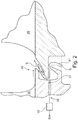
- a labyrinth seal 40 with a sensor arrangement 50 for fluid monitoring are shown.
- the sealing effect is based on an extension of the flow path in the gap to be sealed, as a result of which the flow resistance is increased.
- a labyrinth seal 40 has interlocking parts (interlocking).
- the cutting planes of the Fig. 2 and 3rd comprise the engine axis 1 and thus extend in the radial direction.
- the Fig. 2 and 3rd each show an embodiment in which the flow direction in the aircraft engine 10 runs from left to right.
- the Turbine flow thus first flows through a stator stage 30 with guide vane blades before it strikes a rotor stage 29 with rotor blade blades.
- the labyrinth seal 40 is arranged between the stator disk 30 and the rotor disk 29.
- the fluid flow 41 - here, for example, air - flows radially from the inside to the outside along the flow path S.
- the flow path is delimited here radially inside and outside by the dashed line.
- a sensor element 51 is arranged here directly on the flow path S as part of a sensor device 50, with which a fluid property, namely the temperature in the labyrinth seal 40, is measured here.
- the sensor element 51 is in contact (directly or indirectly) with the fluid flow 41 along the flow path S in the labyrinth seal 40.
- the sensor element 41 is arranged approximately in the middle of the flow path S and is oriented such that the fluid flow 41 flows towards the sensor element 41 .
- FIG. 3 An alternative sensor arrangement 50 is shown in a labyrinth seal 40, referring to the description of FIGS Fig. 2 Can be referenced.
- the sensor element 51 is arranged approximately in the middle of the flow path S.
- the sensor element 51 is flowed against tangentially here.
- the sensor element 41 is arranged at the beginning or end of the flow path S. It is also possible that the sensor element 51 is not arranged at a right angle to the flow path S, but at an acute or obtuse angle. In any case, it is in direct contact with the fluid flowing in the labyrinth seal 40.
- the sensor element 51 of the sensor arrangement 50 is connected to a control device 52 which can emit a control signal 53 if, for example, a certain measured value - here a temperature value - is exceeded or fallen below.
- the temperature rise would be detected. This could then be converted into a control signal 53 via the control device 52.
- the sensor element 51 is arranged approximately in the middle of the fluid flow 41.
- the sensor arrangement is arranged in the stator stage 30.
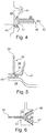
- FIG. 4 A labyrinth seal 40 is shown, which is arranged between a rotor stage 29 on the left and a stator stage 30 on the right.
- the sensor element 51 detects the temperature rise, which is an indicator of the damage, and forwards the information to the control device 52. If a defined threshold value is exceeded, the pilot in the cockpit could be informed of a signal. Furthermore, an automatic shutdown of the aircraft engine would be possible.
- a non-contact seal 40 is arranged between a stator stage 30 at the top and an underlying rotor stage 29.
- a sensor element 51 for example an optical oil sensor, detects, for example, a leak in a storage chamber when the oil flow exceeds a certain amount. The measurement result is forwarded to the control device 52.
- a labyrinth seal 40 is arranged between a stator stage 30 on the left and a rotor stage 29 on the right.
- an optical sensor detects whether combustion products and / or solids flow with the fluid through the labyrinth seal 40. In this case, the optical properties (eg extinction) of the fluid would change, so that a fault in the entry of combustion gases could be detected via the sealing element.
- the measurement result is forwarded to the control device 52.
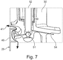
- a perspective view of a non-contact seal 40 between a stator stage and a rotor stage of a turbine is shown.
- the fluid flow 41 is shown, which arises, for example, due to an unplanned intake of a hot gas.
- the sensor element 51 does not act directly at the location of the fluid flow 41.
- the fluid flow 41 is sucked off and over by a pressure gradient present above the stator stage an air duct 54 is guided past the sensor element.
- the sensor arrangement 50 has an approximately cylindrical sensor element 51.
Description
- Die Erfindung bezieht sich auf eine Sensorvorrichtung für eine Turbomaschine mit den Merkmalen des Anspruchs 1 und ein Messverfahren mit den Merkmalen des Anspruchs 6.
- In Turbomaschinen, insbesondere Flugzeugtriebwerken, spielen Fluidströme an vielen Stellen eine Rolle. So ist es z.B. an verschiedenen Stellen der Turbomaschine notwendig, Kühlluft einzusetzen und deren Temperatur zu überwachen. Ein plötzlicher Temperaturanstieg der Kühlluft kann auf ein Problem hindeuten oder ein Problem verursachen. Auch kann es notwendig sein, Arbeitsfluide, wie z.B. Ölflüsse, zu überwachen.
- In der
EP 0 493 111 A1 ist eine Labyrinthdichtung in einer Gasturbine beschrieben. Ein Gasstrom bildet eine ringförmige Strömung aus und eine Sensorvorrichtung misst eine Temperatur an einem Zwischenpunkt des Strompfades. - Es besteht daher die Aufgabe, Sensoranordnungen und Messverfahren zu schaffen, die eine effiziente und zuverlässige Überwachung von Fluiden in der Turbomaschine ermöglichen.
- Die Aufgabe wird auch durch eine Sensoranordnung mit den Merkmalen des Anspruchs 1 gelöst.
- Dabei erfasst das Sensorelement mindestens eine Fluideigenschaft in einer berührungsfreien Dichtung zwischen einer Rotorstufe und einer Statorstufe einer Turbine, insbesondere einer Hochdruckturbine, wobei das Sensorelement im Betrieb einen Kontakt (direkt oder indirekt) mit der Fluidströmung entlang des Strömungspfades in der berührungsfreien Dichtung aufweist. Dabei ist das Sensorelement am Anfang, in der Mitte oder am Ende des Strömungspfades durch die berührungsfreie Dichtung angeordnet. Somit erfolgt die Erfassung direkt in der Dichtung und nicht an einer vorgelagerten oder nachgelagerten Stelle. Die Dichtung mit dem Sensorelement liegt in der Nähe des Gaspfades, um gegen Heißgaseintritt abzudichten und gegebenenfalls einen Heißgaseintritt zu detektieren.
- In einer Ausführungsform besteht über den Strömungspfad ein Druckgefälle, so dass ein Fluid durch die berührungsfreie Dichtung, insbesondere die Labyrinthdichtung, transportiert wird.
- Das Sensorelement kann zusätzlich auch in einer Messkammer positioniert sein, die durch einen Kanal mit der eigentlichen Messstelle in der Dichtung verbunden ist, und somit das zu detektierende Fluid erst durch einen Kanal zum Sensorelement geführt werden muss.
- In Anwendung der Sensoranordnung kann das Sensorelement eine Temperatur der Fluidströmung, insbesondere einer Luftströmung, einen Mengenstrom der Fluidströmung, insbesondere einen Ölfluss und / oder eine Zusammensetzung der Fluidströmung, insbesondere ein Verbrennungsgas, messen. Dabei können z.B. optische Sensoren eingesetzt werden, die die Zusammensetzung, die Leitfähigkeit oder die optische Durchlässigkeit des Fluidstroms erfassen können.
- Dabei ist es auch möglich, dass das Sensorelement mit einer Steuerungsvorrichtung gekoppelt ist, mit der in Abhängigkeit von der Messung des Sensorelementes ein Steuersignal abgebbar ist, welches beispielsweise den Piloten im Cockpit über die Messung informieren oder eine automatische Abschaltung des Flugzeugtriebwerkes einleiten kann.
- Die Aufgabe wird auch durch ein Messverfahren mit den Merkmalen des Anspruchs 6 gelöst.
- Ausführungsformen der Erfindung werden anhand der folgenden Figuren beispielhaft dargestellt. Es zeigt:
- Fig. 1
- eine schematische Darstellung eines Flugzeugtriebwerkes;
- Fig. 2
- eine schematische, vereinfachte Schnittansicht eines ersten Ausführungsbeispiels der erfindungsgemäßen Sensoranordnung in einer Axialschnittebene;
- Fig. 3
- eine schematische, vereinfachte Schnittansicht eines zweiten Ausführungsbeispiels der erfindungsgemäßen Sensoranordnung in einer Axialschnittebene;
- Fig. 4
- eine schematische Ansicht eines Fehlerfalls beim Ansaugen heißen Gases durch eine Labyrinthdichtung;
- Fig. 5
- eine schematische Ansicht eines Fehlerfalls bei einem Ölleck in einer berührungsfreien Dichtung;
- Fig. 6
- eine schematische Ansicht eines Fehlerfalls bei einer Verbrennung;
- Fig. 7
- eine perspektivische Darstellung einer realen, berührungsfreien Dichtung mit einer Ausführungsform einer Sensoranordnung.
- Das Flugzeugtriebwerk 10 gemäß
Fig. 1 zeigt ein allgemeines Beispiel einer Turbomaschine. - Das Flugzeugtriebwerk 10 ist in an sich bekannter Weise meistens als Mehr-Wellen-Triebwerk ausgebildet und umfasst in Strömungsrichtung hintereinander einen Lufteinlass 11, einen in einem Gehäuse umlaufenden Fan 12, gegebenenfalls einen Mitteldruckkompressor 13, einen Hochdruckkompressor 14, eine Brennkammer 15, eine Hochdruckturbine 16, gegebenenfalls eine Mitteldruckturbine 17 und eine Niederdruckturbine 18 sowie eine Abgasdüse 19, die sämtlich um eine zentrale Triebwerksachse 1 angeordnet sind.
- Der Mitteldruckkompressor 13 und der Hochdruckkompressor 14 umfassen jewells mehrere Stufen, von denen jede eine in Umfangsrichtung verlaufende Anordnung fester stationärer Leitschaufeln 20 aufweist, die allgemein als Statorschaufeln bezeichnet werden und die radial nach innen vom Triebwerksgehäuse 21 in einen ringförmigen Strömungskanal durch die Kompressoren 13, 14 vorstehen. Die Kompressoren weisen weiter eine Anordnung von Kompressorlaufschaufeln 22 auf, die radial nach außen von einer drehbaren Trommel oder Scheibe 26 vorstehen, die mit Turbinenrotornaben 27 der Hochdruckturbine 16 bzw. der Mitteldruckturbine 17 gekoppelt sind.
- Die Turbinen 16, 17, 18 weisen ähnliche Stufen auf, umfassend eine Anordnung von festen Leitschaufeln 23, die radial nach innen vom Gehäuse 21 in den ringförmigen Strömungskanal durch die Turbinen 16, 17, 18 vorstehen, und eine nachfolgende Anordnung von Turbinenschaufeln 24, die nach außen von einer drehbaren Turbinenrotornabe 27 vorstehen. Die Kompressortrommel oder Kompressorscheibe 26 und die darauf angeordneten Schaufeln 22 sowie die Turbinenrotornabe 27 und die darauf angeordneten Turbinenlaufschaufeln 24 drehen sich im Betrieb um die Triebwerksachse 1.
- Zwischen den Statoren und Rotoren der Kompressoren 13, 14 und Turbinen 16, 17, 18 befindet sich häufig ein Spalt, direkt am Strömungskanal aber auch weiter innerhalb des Triebwerkes, durch den Fluide, wie z.B. Kühlluft oder Öl, hindurchtreten können. Diese Spalte sind in der Regel mit berührungsfreien Dichtungen 40, wie z.B. einer Labyrinthdichtung, versehen. Dabei ist es für die Funktion des Flugzeugtriebwerks 10 wichtig, den Fluidfluss über die Dichtung 40 zu überwachen.
- In
Fig. 2 und3 sind Ausführungsformen einer Labyrinthdichtung 40 mit einer Sensoranordnung 50 zur Fluidüberwachung dargestellt. Bei einer Labyrinthdichtung 40 beruht die Dichtwirkung auf einer Verlängerung des Strömungsweges im abzudichtenden Spalt, wodurch der Strömungswiderstand erhöht wird. Typischerweise weist eine Labyrinthdichtung 40 ineinandergreifende Teile auf (Verkämmung). - Die Schnittebenen der
Fig. 2 und3 umfassen die Triebwerksachse 1 und erstrecken sich somit in radialer Richtung. - Die
Fig. 2 und3 zeigen jeweils ein Ausführungsbeispiel, bei welchem die Strömungsrichtung im Flugzeugtriebwerk 10 von links nach rechts verläuft. Die Turbinenströmung durchströmt somit zunächst eine Statorstufe 30 mit Leitschaufelblättern, bevor sie auf eine Rotorstufe 29 mit Laufschaufelblättern auftrifft. - In
Fig. 2 ist die Labyrinthdichtung 40 zwischen der Statorscheibe 30 und der Rotorscheibe 29 angeordnet. Die Fluidströmung 41 - hier z.B. Luft - strömt radial von innen nach außen entlang dem Strömungspfad S. Der Strömungspfad wird hier radial innen und außen durch die gestrichelte Linie begrenzt. - Direkt am Strömungspfad S ist hier ein Sensorelement 51 als Teil einer Sensorvorrichtung 50 angeordnet, mit der hier eine Fluideigenschaft, nämlich die Temperatur in der Labyrinthdichtung 40, gemessen wird. Dabei hat das Sensorelement 51 Kontakt (direkt oder indirekt) mit der Fluidströmung 41 entlang des Strömungspfades S in der Labyrinthdichtung 40. Das Sensorelement 41 ist hier in etwa der Mitte des Strömungspfades S angeordnet und so orientiert, dass die Fluidströmung 41 auf das Sensorelement 41 zuströmt.
- In
Fig. 3 ist eine alternative Sensoranordnung 50 in einer Labyrinthdichtung 40 dargestellt, wobei auf die Beschreibung derFig. 2 Bezug genommen werden kann. Auch hier ist das Sensorelement 51 in etwa in der Mitte des Strömungspfades S angeordnet. Allerdings wird das Sensorelement 51 hier tangential angeströmt. - In alternativen Ausführungsformen ist das Sensorelement 41 am Anfang oder Ende des Strömungspfades S angeordnet. Auch ist es möglich, dass das Sensorelement 51 nicht im rechten Winkel zum Strömungspfad S, sondern in einem spitzen oder stumpfen Winkel angeordnet ist. In jedem Fall hat es direkten Kontakt mit dem in der Labyrinthdichtung 40 fließenden Fluid.
- In den Ausführungsformen der
Fig. 2 und3 ist das Sensorelement 51 der Sensoranordnung 50 mit einer Steuervorrichtung 52 verbunden, die ein Steuersignal 53 abgeben kann, wenn z.B. ein bestimmter Messwert - hier ein Temperaturwert - über- oder unterschritten wird. - Wenn z.B. auf Grund einer Fehlfunktion heißes Gas von außen nach innen durch die Labyrinthdichtung 40 strömen würde, so würde der Temperaturanstieg detektiert werden. Dies könnte dann über die Steuervorrichtung 52 in ein Steuersignal 53 umgesetzt werden. In
Fig. 4 bis 6 sind einige solche Fälle schematisch dargestellt. In allen drei Fällen ist das Sensorelement 51 in etwa in der Mitte des Fluidflusses 41 angeordnet. Die Sensoranordnung ist jeweils in der Statorstufe 30 angeordnet. - In
Fig. 4 ist eine Labyrinthdichtung 40 dargestellt, die zwischen einer Rotorstufe 29 links und einer Statorstufe 30 rechts angeordnet ist. Hier ist der Fall dargestellt, dass bei einem Schadensfall im Flugzeugtriebwerk 10 heißes Gas von außen radial nach innen durch die Labyrinthdichtung 40 strömt. Das Sensorelement 51 detektiert den Temperaturanstieg, der ein Indikator für den Schaden ist und leitet die Information an die Steuervorrichtung 52 weiter. Bei der Überschreitung eines definierten Schwellenwertes könnte der Pilot im Cockpit über ein Signal informiert werden. Des Weiteren wäre eine automatische Abschaltung des Flugzeugtriebwerkes möglich. - In
Fig. 5 ist eine weitere Anwendung der Sensoranordnung 50 dargestellt, bei der es um die Erfassung eines Öllecks geht. Hier ist eine berührungslose Dichtung 40 zwischen einer Statorstufe 30 oben und einer darunterliegenden Rotorstufe 29 angeordnet. Ein Sensorelement 51, z.B. eines optischen Ölsensors, erfasst z.B. ein Leck einer Lagerkammer, wenn der Ölfluss über eine bestimmte Menge hinausgeht. Das Messergebnis wird an die Steuervorrichtung 52 weitergeleitet. - In
Fig. 6 ist eine Labyrinthdichtung 40 zwischen einer Statorstufe 30 links und einer Rotorstufe 29 rechts angeordnet. Hier erfasst ein optischer Sensor, ob Verbrennungsprodukte und / oder Festkörper mit dem Fluid durch die Labyrinthdichtung 40 strömen. In diesem Fall würden sich die optischen Eigenschaften (z.B. Extinktion) des Fluids verändern, so dass ein Fehlerfall des Eintritts von Verbrennungsgasen über das Dichtungselement erfasst werden könnte. Auch hier wird das Messergebnis an die Steuervorrichtung 52 weitergeleitet. - In
Fig. 7 ist eine perspektivische Ansicht einer berührungsfreien Dichtung 40 zwischen einer Statorstufe und einer Rotorstufe einer Turbine dargestellt. InFig. 7 ist die Fluidströmung 41 dargestellt, die sich z.B. auf Grund eines ungeplanten Ansaugens eines heißen Gases einstellt. Das Sensorelement 51 wirkt in diesem Fall nicht direkt am Ort der Fluidströmung 41. Damit das heiße Gas jedoch ebenfalls unmittelbar detektiert werden kann, bevor es weiter ins Innere des Flugzeugtriebwerks 10 eintritt, wird die Fluidströmung 41 durch ein über der Statorstufe vorhandenes Druckgefälle abgesaugt und über einen Luftkanal 54 an dem Sensorelement vorbeigeführt. Durch das Auslegen eines kurzen Kanals wird eine verzögerte Reaktion auf den Eintritt des heißen Gases minimiert, jedoch auch eine vereinfachte Ausführung, hier insbesondere eines geraden Sensorelementes 51, ermöglicht. Diese einfache Bauweise des Sensors ermöglicht dann einen Austausch des Elementes mit Triebwerken, welche noch am Flugzeug montiert sind. - In der hier dargestellten Ausführungsform weist die Sensoranordnung 50 ein in etwa zylindrisches Sensorelement 51 auf.
-
- 1
- Triebwerksachse
- 10
- Gasturbinentriebwerk, Flugzeugtriebwerk
- 11
- Lufteinlass
- 12
- Fan
- 13
- Mitteldruckkompressor (Verdichter)
- 14
- Hochdruckkompressor
- 15
- Brennkammer
- 16
- Hochdruckturbine
- 17
- Mitteldruckturbine
- 18
- Niederdruckturbine
- 19
- Abgasdüse
- 20
- Kompressorleitschaufeln
- 21
- Triebwerksgehäuse
- 22
- Kompressorlaufschaufeln
- 23
- Turbinenleitschaufeln
- 24
- Turbinenlaufschaufeln
- 26
- Kompressortrommel oder-scheibe
- 27
- Turbinenrotornabe
- 29
- Rotorstufe
- 30
- Statorstufe
- 40
- Dichtung, Labyrinthdichtung
- 41
- Fluidströmung
- 50
- Sensoranordnung
- 51
- Sensorelement
- 52
- Steuerungsvorrichtung
- 53
- Steuersignal
- 54
- Luftkanal
- S
- Strömungspfad in Labyrinthdichtung
Claims (6)
- Sensoranordnung (50) mit einem Sensorelement (51) für die Messung mindestens einer physikalischen und / oder chemischen Fluideigenschaft in einer Turbomaschine (10), die eine Turbine (16, 17, 18), insbesondere einer Hochdruckturbine (16), aufweist, in der eine Rotorstufe (29) und eine Statorstufe (30) angeordnet sind,
dadurch gekennzeichnet, dass
das Sensorelement (51) die mindestens eine Fluideigenschaft in einer berührungsfreien Dichtung, insbesondere einer Labyrinthdichtung (40), zwischen der Rotorstufe (29) und der Statorstufe (30) erfasst, wobei das Sensorelement (51) im Betrieb einen Kontakt mit der Fluidströmung (41) entlang des Strömungspfades (S) in der berührungsfreien Dichtung (40) aufweist, wobei das Sensorelement (51) am Anfang, in der Mitte oder am Ende des Strömungspfades (S) durch die berührungsfreie Dichtung angeordnet ist, wobei die Dichtung (40) mit dem Sensorelement (51) in der Nähe des Gaspfades liegt, um gegen Heißgaseintritt abzudichten und gegebenenfalls einen Heißgaseintritt zu detektieren. - Sensoranordnung nach Anspruch 1, dadurch gekennzeichnet, dass über den Strömungspfad (S) ein Druckgefälle besteht, so dass ein Fluid durch die berührungsfreie Dichtung, insbesondere die Labyrinthdichtung (40), transportiert wird.
- Sensoranordnung nach mindestens einem der vorhergegangen Ansprüche, dadurch gekennzeichnet, dass das Sensorelement (51) in einer Messkammer positioniert ist, die durch einen Kanal mit der eigentlichen Messstelle in der Dichtung (40) verbunden ist, und somit das zu detektierende Fluid erst durch einen Kanal zum Sensorelement (51) geführt werden muss.
- Sensoranordnung nach mindestens einem der vorhergehenden Ansprüche, dadurch gekennzeichnet, dass mit dem Sensorelement (51) eine Temperatur der Fluidströmung (41), insbesondere einer Luftströmung, ein Mengenstrom der Fluidströmung (41), insbesondere ein Ölfluss und / oder eine Zusammensetzung der Fluidströmung (41), insbesondere eines Verbrennungsgases, messbar ist.
- Sensoranordnung nach mindestens einem der vorhergehenden Ansprüche, dadurch gekennzeichnet, dass das Sensorelement (51) mit einer Steuerungsvorrichtung (52) gekoppelt ist, mit der in Abhängigkeit von der Messung mit dem Sensorelement (51) ein Steuersignal (53) abgebbar ist.
- Messverfahren mit einem Sensorelement (51) für die Messung mindestens einer physikalischen und / oder chemischen Fluideigenschaft in einer Turbomaschine (10), die eine Turbine (16, 17, 18), insbesondere einer Hochdruckturbine (16), aufweist, in der eine Rotorstufe (29) und eine Statorstufe (30) angeordnet sind,
dadurch gekennzeichnet, dass
das Sensorelement (51) die mindestens eine Fluideigenschaft in einer berührungsfreien Dichtung, insbesondere einer Labyrinthdichtung (40), zwischen der Rotorstufe (29) und der Statorstufe (30) erfasst, wobei die Messung durch das Sensorelement (51) im Betrieb durch einen Kontakt mit der Strömung des Fluides entlang des Strömungspfades (S) in der berührungsfreien Dichtung (40) erfolgt, wobei das Sensorelement (51) am Anfang, in der Mitte oder am Ende des Strömungspfades (S) durch die berührungsfreie Dichtung angeordnet ist, wobei die Dichtung (40) mit dem Sensorelement (51) in der Nähe des Gaspfades liegt, um gegen Heißgaseintritt abzudichten und gegebenenfalls einen Heißgaseintritt zu detektieren.
Applications Claiming Priority (1)
| Application Number | Priority Date | Filing Date | Title |
|---|---|---|---|
| DE102015226732.6A DE102015226732A1 (de) | 2015-12-24 | 2015-12-24 | Sensoranordnung und Messverfahren für eine Turbomaschine |
Publications (2)
| Publication Number | Publication Date |
|---|---|
| EP3184754A1 EP3184754A1 (de) | 2017-06-28 |
| EP3184754B1 true EP3184754B1 (de) | 2020-07-08 |
Family
ID=57749674
Family Applications (1)
| Application Number | Title | Priority Date | Filing Date |
|---|---|---|---|
| EP16205345.8A Active EP3184754B1 (de) | 2015-12-24 | 2016-12-20 | Sensoranordnung und messverfahren für eine turbomaschine |
Country Status (3)
| Country | Link |
|---|---|
| US (1) | US20170184472A1 (de) |
| EP (1) | EP3184754B1 (de) |
| DE (1) | DE102015226732A1 (de) |
Families Citing this family (6)
| Publication number | Priority date | Publication date | Assignee | Title |
|---|---|---|---|---|
| US9983189B2 (en) * | 2016-02-26 | 2018-05-29 | Pratt & Whitney Canada Corp. | Detection of oil contamination in engine air |
| DE102017205573A1 (de) | 2017-03-31 | 2018-10-04 | Rolls-Royce Deutschland Ltd & Co Kg | Messvorrichtung und Messverfahren für eine Strömung |
| US10927845B2 (en) * | 2017-05-24 | 2021-02-23 | The Boeing Company | Seal assembly and method for reducing aircraft engine oil leakage |
| DE102019123240A1 (de) * | 2019-08-29 | 2021-03-04 | Rolls-Royce Deutschland Ltd & Co Kg | Messvorrichtung und -verfahren für ein Flugzeugtriebwerk und ein Flugzeugtriebwerk |
| DE102020101324A1 (de) | 2020-01-21 | 2021-07-22 | Rolls-Royce Deutschland Ltd & Co Kg | Baugruppe in einem Gasturbinentriebwerk und Verfahren zur Erkennung eines Versagens eines Schublagers |
| US11504813B2 (en) | 2020-05-18 | 2022-11-22 | Rolls-Royce Plc | Methods for health monitoring of ceramic matrix composite components in gas turbine engines |
Family Cites Families (8)
| Publication number | Priority date | Publication date | Assignee | Title |
|---|---|---|---|---|
| US4406577A (en) * | 1979-10-29 | 1983-09-27 | Tokyo Shibaura Denki Kabushiki Kaisha | Multi-stage hydraulic machine and a method of operating same |
| US4332133A (en) * | 1979-11-14 | 1982-06-01 | United Technologies Corporation | Compressor bleed system for cooling and clearance control |
| US5157914A (en) * | 1990-12-27 | 1992-10-27 | United Technologies Corporation | Modulated gas turbine cooling air |
| ITCO20110036A1 (it) * | 2011-09-07 | 2013-03-08 | Nuovo Pignone Spa | Guarnizione per una macchina rotante |
| US10598222B2 (en) * | 2012-01-03 | 2020-03-24 | New Way Machine Components, Inc. | Air bearing for use as seal |
| JP5818717B2 (ja) * | 2012-02-27 | 2015-11-18 | 三菱日立パワーシステムズ株式会社 | ガスタービン |
| US9482078B2 (en) * | 2012-06-25 | 2016-11-01 | Zeitecs B.V. | Diffuser for cable suspended dewatering pumping system |
| DE102013220455A1 (de) * | 2013-10-10 | 2015-04-16 | Rolls-Royce Deutschland Ltd & Co Kg | Gasturbinentriebwerk mit Kühlluftringkammer |
-
2015
- 2015-12-24 DE DE102015226732.6A patent/DE102015226732A1/de not_active Withdrawn
-
2016
- 2016-12-15 US US15/380,389 patent/US20170184472A1/en not_active Abandoned
- 2016-12-20 EP EP16205345.8A patent/EP3184754B1/de active Active
Non-Patent Citations (1)
| Title |
|---|
| None * |
Also Published As
| Publication number | Publication date |
|---|---|
| DE102015226732A1 (de) | 2017-06-29 |
| US20170184472A1 (en) | 2017-06-29 |
| EP3184754A1 (de) | 2017-06-28 |
Similar Documents
| Publication | Publication Date | Title |
|---|---|---|
| EP3184754B1 (de) | Sensoranordnung und messverfahren für eine turbomaschine | |
| DE4225642C1 (de) | ||
| CH700957B1 (de) | Fehlererkennungs- und Schutzsystem für mehrstufige Rotationsmaschinen. | |
| WO2006005319A2 (de) | Einrichtung zur detektion eines wellenbruchs an einer gasturbine sowie gasturbine | |
| DE10318852A1 (de) | Hauptgaskanal-Innendichtung einer Hochdruckturbine | |
| DE102017213090A1 (de) | Anordnung, Turbomaschine und Verfahren zur Erkennung eines Wellenbruchs einer Welle | |
| DE112012004549T5 (de) | Diagnoseverfahren und -Systeme für einen Turbolader | |
| EP2805058B1 (de) | VERFAHREN ZUR VERMEIDUNG VON PUMPSTÖßEN IN EINEM VERDICHTER | |
| EP3358147B1 (de) | Zustandsanzeige eines bypassventilsystems | |
| EP2299062A1 (de) | Dichtungssegment für eine Strömungsmaschine | |
| EP2956630B1 (de) | Gasturbine und verfahren zum betreiben der gasturbine | |
| EP3589843B1 (de) | Verfahren und vorrichtung zum bestimmen eines indikators für eine vorhersage einer instabilität in einem verdichter sowie verwendung | |
| DE102012100170A1 (de) | Verfahren, Systeme und Vorrichtungen zum Erkennen von Materialdefekten in Brennkammern von Verbrennungskraft-Turbinenmaschinen | |
| EP2924414B1 (de) | Druckmessvorrichtung zur messung dynamischer drücke sowie gasturbinenbrennkammer mit einer druckmessvorrichtung | |
| EP0690204B1 (de) | Kondensationsturbine mit mindestens zwei Dichtungen zur Abdichtung des Turbinengehäuses | |
| EP2806110A1 (de) | Turbomaschinenstufe und Verfahren zum Ermitteln eines Dichtungsspalts einer solchen Turbomaschinenstufe | |
| EP3330494B1 (de) | Anordnung, turbomaschine und verfahren zur erkennung eines wellenbruchs | |
| Rückert et al. | A Novel Stall Warning Indicator: Part I—Applications and Limitations | |
| DE102017216279A1 (de) | Verfahren zur Erkennung einer Fehlstellung der Winkellage einer in einem Verdichter angeordneten, um ihre Längsachse schwenkbaren Verdichterleitschaufel | |
| DE112020001492T5 (de) | Verdichtersystem | |
| WO2015090566A1 (de) | Verdichterstufe | |
| DE102014218937A1 (de) | Wellendichtung, Verfahren zum Betrieb | |
| EP3106627A1 (de) | Verdichterüberwachung in einer strömungsmaschine | |
| DE102011051477A1 (de) | Verfahren und Vorrichtung zum Zusammenbau von Rotationsmaschinen | |
| DE102008034322B4 (de) | Verfahren und Vorrichtung zur Bestimmung des Auftretens von kleineren Druckschwingungen vor einem Pumpstoß bei einem Verdichter eines Turboladers |
Legal Events
| Date | Code | Title | Description |
|---|---|---|---|
| PUAI | Public reference made under article 153(3) epc to a published international application that has entered the european phase |
Free format text: ORIGINAL CODE: 0009012 |
|
| STAA | Information on the status of an ep patent application or granted ep patent |
Free format text: STATUS: THE APPLICATION HAS BEEN PUBLISHED |
|
| AK | Designated contracting states |
Kind code of ref document: A1 Designated state(s): AL AT BE BG CH CY CZ DE DK EE ES FI FR GB GR HR HU IE IS IT LI LT LU LV MC MK MT NL NO PL PT RO RS SE SI SK SM TR |
|
| AX | Request for extension of the european patent |
Extension state: BA ME |
|
| STAA | Information on the status of an ep patent application or granted ep patent |
Free format text: STATUS: REQUEST FOR EXAMINATION WAS MADE |
|
| 17P | Request for examination filed |
Effective date: 20171227 |
|
| RBV | Designated contracting states (corrected) |
Designated state(s): AL AT BE BG CH CY CZ DE DK EE ES FI FR GB GR HR HU IE IS IT LI LT LU LV MC MK MT NL NO PL PT RO RS SE SI SK SM TR |
|
| GRAP | Despatch of communication of intention to grant a patent |
Free format text: ORIGINAL CODE: EPIDOSNIGR1 |
|
| STAA | Information on the status of an ep patent application or granted ep patent |
Free format text: STATUS: GRANT OF PATENT IS INTENDED |
|
| RIC1 | Information provided on ipc code assigned before grant |
Ipc: F01D 17/08 20060101ALI20191009BHEP Ipc: F01D 21/00 20060101ALI20191009BHEP Ipc: F01D 11/00 20060101AFI20191009BHEP |
|
| INTG | Intention to grant announced |
Effective date: 20191111 |
|
| RIN1 | Information on inventor provided before grant (corrected) |
Inventor name: ALBELT, STEFAN Inventor name: FECHNER, STEFAN |
|
| GRAJ | Information related to disapproval of communication of intention to grant by the applicant or resumption of examination proceedings by the epo deleted |
Free format text: ORIGINAL CODE: EPIDOSDIGR1 |
|
| STAA | Information on the status of an ep patent application or granted ep patent |
Free format text: STATUS: REQUEST FOR EXAMINATION WAS MADE |
|
| INTC | Intention to grant announced (deleted) | ||
| GRAJ | Information related to disapproval of communication of intention to grant by the applicant or resumption of examination proceedings by the epo deleted |
Free format text: ORIGINAL CODE: EPIDOSDIGR1 |
|
| GRAP | Despatch of communication of intention to grant a patent |
Free format text: ORIGINAL CODE: EPIDOSNIGR1 |
|
| GRAR | Information related to intention to grant a patent recorded |
Free format text: ORIGINAL CODE: EPIDOSNIGR71 |
|
| GRAS | Grant fee paid |
Free format text: ORIGINAL CODE: EPIDOSNIGR3 |
|
| STAA | Information on the status of an ep patent application or granted ep patent |
Free format text: STATUS: GRANT OF PATENT IS INTENDED |
|
| GRAA | (expected) grant |
Free format text: ORIGINAL CODE: 0009210 |
|
| STAA | Information on the status of an ep patent application or granted ep patent |
Free format text: STATUS: THE PATENT HAS BEEN GRANTED |
|
| INTG | Intention to grant announced |
Effective date: 20200527 |
|
| AK | Designated contracting states |
Kind code of ref document: B1 Designated state(s): AL AT BE BG CH CY CZ DE DK EE ES FI FR GB GR HR HU IE IS IT LI LT LU LV MC MK MT NL NO PL PT RO RS SE SI SK SM TR |
|
| REG | Reference to a national code |
Ref country code: AT Ref legal event code: REF Ref document number: 1288667 Country of ref document: AT Kind code of ref document: T Effective date: 20200715 Ref country code: CH Ref legal event code: EP |
|
| REG | Reference to a national code |
Ref country code: DE Ref legal event code: R096 Ref document number: 502016010433 Country of ref document: DE |
|
| REG | Reference to a national code |
Ref country code: IE Ref legal event code: FG4D Free format text: LANGUAGE OF EP DOCUMENT: GERMAN |
|
| REG | Reference to a national code |
Ref country code: LT Ref legal event code: MG4D |
|
| REG | Reference to a national code |
Ref country code: NL Ref legal event code: MP Effective date: 20200708 |
|
| PG25 | Lapsed in a contracting state [announced via postgrant information from national office to epo] |
Ref country code: PT Free format text: LAPSE BECAUSE OF FAILURE TO SUBMIT A TRANSLATION OF THE DESCRIPTION OR TO PAY THE FEE WITHIN THE PRESCRIBED TIME-LIMIT Effective date: 20201109 Ref country code: LT Free format text: LAPSE BECAUSE OF FAILURE TO SUBMIT A TRANSLATION OF THE DESCRIPTION OR TO PAY THE FEE WITHIN THE PRESCRIBED TIME-LIMIT Effective date: 20200708 Ref country code: ES Free format text: LAPSE BECAUSE OF FAILURE TO SUBMIT A TRANSLATION OF THE DESCRIPTION OR TO PAY THE FEE WITHIN THE PRESCRIBED TIME-LIMIT Effective date: 20200708 Ref country code: BG Free format text: LAPSE BECAUSE OF FAILURE TO SUBMIT A TRANSLATION OF THE DESCRIPTION OR TO PAY THE FEE WITHIN THE PRESCRIBED TIME-LIMIT Effective date: 20201008 Ref country code: HR Free format text: LAPSE BECAUSE OF FAILURE TO SUBMIT A TRANSLATION OF THE DESCRIPTION OR TO PAY THE FEE WITHIN THE PRESCRIBED TIME-LIMIT Effective date: 20200708 Ref country code: FI Free format text: LAPSE BECAUSE OF FAILURE TO SUBMIT A TRANSLATION OF THE DESCRIPTION OR TO PAY THE FEE WITHIN THE PRESCRIBED TIME-LIMIT Effective date: 20200708 Ref country code: GR Free format text: LAPSE BECAUSE OF FAILURE TO SUBMIT A TRANSLATION OF THE DESCRIPTION OR TO PAY THE FEE WITHIN THE PRESCRIBED TIME-LIMIT Effective date: 20201009 Ref country code: SE Free format text: LAPSE BECAUSE OF FAILURE TO SUBMIT A TRANSLATION OF THE DESCRIPTION OR TO PAY THE FEE WITHIN THE PRESCRIBED TIME-LIMIT Effective date: 20200708 Ref country code: NO Free format text: LAPSE BECAUSE OF FAILURE TO SUBMIT A TRANSLATION OF THE DESCRIPTION OR TO PAY THE FEE WITHIN THE PRESCRIBED TIME-LIMIT Effective date: 20201008 |
|
| PG25 | Lapsed in a contracting state [announced via postgrant information from national office to epo] |
Ref country code: IS Free format text: LAPSE BECAUSE OF FAILURE TO SUBMIT A TRANSLATION OF THE DESCRIPTION OR TO PAY THE FEE WITHIN THE PRESCRIBED TIME-LIMIT Effective date: 20201108 Ref country code: RS Free format text: LAPSE BECAUSE OF FAILURE TO SUBMIT A TRANSLATION OF THE DESCRIPTION OR TO PAY THE FEE WITHIN THE PRESCRIBED TIME-LIMIT Effective date: 20200708 Ref country code: LV Free format text: LAPSE BECAUSE OF FAILURE TO SUBMIT A TRANSLATION OF THE DESCRIPTION OR TO PAY THE FEE WITHIN THE PRESCRIBED TIME-LIMIT Effective date: 20200708 Ref country code: PL Free format text: LAPSE BECAUSE OF FAILURE TO SUBMIT A TRANSLATION OF THE DESCRIPTION OR TO PAY THE FEE WITHIN THE PRESCRIBED TIME-LIMIT Effective date: 20200708 |
|
| PG25 | Lapsed in a contracting state [announced via postgrant information from national office to epo] |
Ref country code: NL Free format text: LAPSE BECAUSE OF FAILURE TO SUBMIT A TRANSLATION OF THE DESCRIPTION OR TO PAY THE FEE WITHIN THE PRESCRIBED TIME-LIMIT Effective date: 20200708 |
|
| REG | Reference to a national code |
Ref country code: DE Ref legal event code: R097 Ref document number: 502016010433 Country of ref document: DE |
|
| PG25 | Lapsed in a contracting state [announced via postgrant information from national office to epo] |
Ref country code: SM Free format text: LAPSE BECAUSE OF FAILURE TO SUBMIT A TRANSLATION OF THE DESCRIPTION OR TO PAY THE FEE WITHIN THE PRESCRIBED TIME-LIMIT Effective date: 20200708 Ref country code: RO Free format text: LAPSE BECAUSE OF FAILURE TO SUBMIT A TRANSLATION OF THE DESCRIPTION OR TO PAY THE FEE WITHIN THE PRESCRIBED TIME-LIMIT Effective date: 20200708 Ref country code: DK Free format text: LAPSE BECAUSE OF FAILURE TO SUBMIT A TRANSLATION OF THE DESCRIPTION OR TO PAY THE FEE WITHIN THE PRESCRIBED TIME-LIMIT Effective date: 20200708 Ref country code: CZ Free format text: LAPSE BECAUSE OF FAILURE TO SUBMIT A TRANSLATION OF THE DESCRIPTION OR TO PAY THE FEE WITHIN THE PRESCRIBED TIME-LIMIT Effective date: 20200708 Ref country code: IT Free format text: LAPSE BECAUSE OF FAILURE TO SUBMIT A TRANSLATION OF THE DESCRIPTION OR TO PAY THE FEE WITHIN THE PRESCRIBED TIME-LIMIT Effective date: 20200708 Ref country code: EE Free format text: LAPSE BECAUSE OF FAILURE TO SUBMIT A TRANSLATION OF THE DESCRIPTION OR TO PAY THE FEE WITHIN THE PRESCRIBED TIME-LIMIT Effective date: 20200708 |
|
| PLBE | No opposition filed within time limit |
Free format text: ORIGINAL CODE: 0009261 |
|
| STAA | Information on the status of an ep patent application or granted ep patent |
Free format text: STATUS: NO OPPOSITION FILED WITHIN TIME LIMIT |
|
| PG25 | Lapsed in a contracting state [announced via postgrant information from national office to epo] |
Ref country code: AL Free format text: LAPSE BECAUSE OF FAILURE TO SUBMIT A TRANSLATION OF THE DESCRIPTION OR TO PAY THE FEE WITHIN THE PRESCRIBED TIME-LIMIT Effective date: 20200708 |
|
| 26N | No opposition filed |
Effective date: 20210409 |
|
| PG25 | Lapsed in a contracting state [announced via postgrant information from national office to epo] |
Ref country code: SK Free format text: LAPSE BECAUSE OF FAILURE TO SUBMIT A TRANSLATION OF THE DESCRIPTION OR TO PAY THE FEE WITHIN THE PRESCRIBED TIME-LIMIT Effective date: 20200708 |
|
| REG | Reference to a national code |
Ref country code: CH Ref legal event code: PL |
|
| GBPC | Gb: european patent ceased through non-payment of renewal fee |
Effective date: 20201220 |
|
| PG25 | Lapsed in a contracting state [announced via postgrant information from national office to epo] |
Ref country code: MC Free format text: LAPSE BECAUSE OF FAILURE TO SUBMIT A TRANSLATION OF THE DESCRIPTION OR TO PAY THE FEE WITHIN THE PRESCRIBED TIME-LIMIT Effective date: 20200708 Ref country code: SI Free format text: LAPSE BECAUSE OF FAILURE TO SUBMIT A TRANSLATION OF THE DESCRIPTION OR TO PAY THE FEE WITHIN THE PRESCRIBED TIME-LIMIT Effective date: 20200708 |
|
| REG | Reference to a national code |
Ref country code: BE Ref legal event code: MM Effective date: 20201231 |
|
| PG25 | Lapsed in a contracting state [announced via postgrant information from national office to epo] |
Ref country code: IE Free format text: LAPSE BECAUSE OF NON-PAYMENT OF DUE FEES Effective date: 20201220 Ref country code: LU Free format text: LAPSE BECAUSE OF NON-PAYMENT OF DUE FEES Effective date: 20201220 |
|
| PG25 | Lapsed in a contracting state [announced via postgrant information from national office to epo] |
Ref country code: CH Free format text: LAPSE BECAUSE OF NON-PAYMENT OF DUE FEES Effective date: 20201231 Ref country code: LI Free format text: LAPSE BECAUSE OF NON-PAYMENT OF DUE FEES Effective date: 20201231 Ref country code: GB Free format text: LAPSE BECAUSE OF NON-PAYMENT OF DUE FEES Effective date: 20201220 |
|
| PG25 | Lapsed in a contracting state [announced via postgrant information from national office to epo] |
Ref country code: IS Free format text: LAPSE BECAUSE OF FAILURE TO SUBMIT A TRANSLATION OF THE DESCRIPTION OR TO PAY THE FEE WITHIN THE PRESCRIBED TIME-LIMIT Effective date: 20201108 Ref country code: TR Free format text: LAPSE BECAUSE OF FAILURE TO SUBMIT A TRANSLATION OF THE DESCRIPTION OR TO PAY THE FEE WITHIN THE PRESCRIBED TIME-LIMIT Effective date: 20200708 Ref country code: MT Free format text: LAPSE BECAUSE OF FAILURE TO SUBMIT A TRANSLATION OF THE DESCRIPTION OR TO PAY THE FEE WITHIN THE PRESCRIBED TIME-LIMIT Effective date: 20200708 Ref country code: CY Free format text: LAPSE BECAUSE OF FAILURE TO SUBMIT A TRANSLATION OF THE DESCRIPTION OR TO PAY THE FEE WITHIN THE PRESCRIBED TIME-LIMIT Effective date: 20200708 |
|
| PG25 | Lapsed in a contracting state [announced via postgrant information from national office to epo] |
Ref country code: MK Free format text: LAPSE BECAUSE OF FAILURE TO SUBMIT A TRANSLATION OF THE DESCRIPTION OR TO PAY THE FEE WITHIN THE PRESCRIBED TIME-LIMIT Effective date: 20200708 |
|
| PG25 | Lapsed in a contracting state [announced via postgrant information from national office to epo] |
Ref country code: BE Free format text: LAPSE BECAUSE OF NON-PAYMENT OF DUE FEES Effective date: 20201231 |
|
| REG | Reference to a national code |
Ref country code: AT Ref legal event code: MM01 Ref document number: 1288667 Country of ref document: AT Kind code of ref document: T Effective date: 20211220 |
|
| PG25 | Lapsed in a contracting state [announced via postgrant information from national office to epo] |
Ref country code: AT Free format text: LAPSE BECAUSE OF NON-PAYMENT OF DUE FEES Effective date: 20211220 |
|
| PGFP | Annual fee paid to national office [announced via postgrant information from national office to epo] |
Ref country code: DE Payment date: 20221227 Year of fee payment: 7 |
|
| P01 | Opt-out of the competence of the unified patent court (upc) registered |
Effective date: 20230528 |
|
| PGFP | Annual fee paid to national office [announced via postgrant information from national office to epo] |
Ref country code: FR Payment date: 20231226 Year of fee payment: 8 |