EP3183174B1 - Pipettiersystem - Google Patents
Pipettiersystem Download PDFInfo
- Publication number
- EP3183174B1 EP3183174B1 EP15756279.4A EP15756279A EP3183174B1 EP 3183174 B1 EP3183174 B1 EP 3183174B1 EP 15756279 A EP15756279 A EP 15756279A EP 3183174 B1 EP3183174 B1 EP 3183174B1
- Authority
- EP
- European Patent Office
- Prior art keywords
- biasing member
- pipette assembly
- container
- liquid
- cannula
- Prior art date
- Legal status (The legal status is an assumption and is not a legal conclusion. Google has not performed a legal analysis and makes no representation as to the accuracy of the status listed.)
- Active
Links
Images


Classifications
-
- G—PHYSICS
- G01—MEASURING; TESTING
- G01N—INVESTIGATING OR ANALYSING MATERIALS BY DETERMINING THEIR CHEMICAL OR PHYSICAL PROPERTIES
- G01N35/00—Automatic analysis not limited to methods or materials provided for in any single one of groups G01N1/00 - G01N33/00; Handling materials therefor
- G01N35/10—Devices for transferring samples or any liquids to, in, or from, the analysis apparatus, e.g. suction devices, injection devices
- G01N35/1009—Characterised by arrangements for controlling the aspiration or dispense of liquids
-
- B—PERFORMING OPERATIONS; TRANSPORTING
- B01—PHYSICAL OR CHEMICAL PROCESSES OR APPARATUS IN GENERAL
- B01L—CHEMICAL OR PHYSICAL LABORATORY APPARATUS FOR GENERAL USE
- B01L3/00—Containers or dishes for laboratory use, e.g. laboratory glassware; Droppers
- B01L3/02—Burettes; Pipettes
- B01L3/021—Pipettes, i.e. with only one conduit for withdrawing and redistributing liquids
- B01L3/0217—Pipettes, i.e. with only one conduit for withdrawing and redistributing liquids of the plunger pump type
-
- B—PERFORMING OPERATIONS; TRANSPORTING
- B01—PHYSICAL OR CHEMICAL PROCESSES OR APPARATUS IN GENERAL
- B01L—CHEMICAL OR PHYSICAL LABORATORY APPARATUS FOR GENERAL USE
- B01L3/00—Containers or dishes for laboratory use, e.g. laboratory glassware; Droppers
- B01L3/02—Burettes; Pipettes
- B01L3/0275—Interchangeable or disposable dispensing tips
-
- B—PERFORMING OPERATIONS; TRANSPORTING
- B65—CONVEYING; PACKING; STORING; HANDLING THIN OR FILAMENTARY MATERIAL
- B65B—MACHINES, APPARATUS OR DEVICES FOR, OR METHODS OF, PACKAGING ARTICLES OR MATERIALS; UNPACKING
- B65B3/00—Packaging plastic material, semiliquids, liquids or mixed solids and liquids, in individual containers or receptacles, e.g. bags, sacks, boxes, cartons, cans, or jars
- B65B3/003—Filling medical containers such as ampoules, vials, syringes or the like
-
- B—PERFORMING OPERATIONS; TRANSPORTING
- B65—CONVEYING; PACKING; STORING; HANDLING THIN OR FILAMENTARY MATERIAL
- B65B—MACHINES, APPARATUS OR DEVICES FOR, OR METHODS OF, PACKAGING ARTICLES OR MATERIALS; UNPACKING
- B65B39/00—Nozzles, funnels or guides for introducing articles or materials into containers or wrappers
- B65B39/12—Nozzles, funnels or guides for introducing articles or materials into containers or wrappers movable towards or away from container or wrapper during filling or depositing
-
- B—PERFORMING OPERATIONS; TRANSPORTING
- B01—PHYSICAL OR CHEMICAL PROCESSES OR APPARATUS IN GENERAL
- B01L—CHEMICAL OR PHYSICAL LABORATORY APPARATUS FOR GENERAL USE
- B01L2200/00—Solutions for specific problems relating to chemical or physical laboratory apparatus
- B01L2200/02—Adapting objects or devices to another
- B01L2200/025—Align devices or objects to ensure defined positions relative to each other
-
- B—PERFORMING OPERATIONS; TRANSPORTING
- B01—PHYSICAL OR CHEMICAL PROCESSES OR APPARATUS IN GENERAL
- B01L—CHEMICAL OR PHYSICAL LABORATORY APPARATUS FOR GENERAL USE
- B01L2200/00—Solutions for specific problems relating to chemical or physical laboratory apparatus
- B01L2200/14—Process control and prevention of errors
-
- B—PERFORMING OPERATIONS; TRANSPORTING
- B01—PHYSICAL OR CHEMICAL PROCESSES OR APPARATUS IN GENERAL
- B01L—CHEMICAL OR PHYSICAL LABORATORY APPARATUS FOR GENERAL USE
- B01L2300/00—Additional constructional details
- B01L2300/06—Auxiliary integrated devices, integrated components
- B01L2300/0672—Integrated piercing tool
-
- B—PERFORMING OPERATIONS; TRANSPORTING
- B01—PHYSICAL OR CHEMICAL PROCESSES OR APPARATUS IN GENERAL
- B01L—CHEMICAL OR PHYSICAL LABORATORY APPARATUS FOR GENERAL USE
- B01L2300/00—Additional constructional details
- B01L2300/08—Geometry, shape and general structure
- B01L2300/0848—Specific forms of parts of containers
- B01L2300/0858—Side walls
Definitions
- the present invention relates primarily to a pipetting apparatus, which provides for dispensing of one or more liquids into containers.
- US 2001/0028864 A1 discloses a pipetting station having a bottom sensing device.
- Dispensing relatively small volumes of liquids into individual containers in a precise and repeatable manner is desirable for a wide range of applications.
- Various types of liquid handling instruments can be used for such purposes, which range from simple hand-held devices to large-scale, automated pipetting apparatus.
- the liquid to be dispensed is introduced from a reservoir into one or a series of pipettes, which pipettes comprise an elongated chamber configured at the proximal end to accept the liquid to be dispensed and having a tip at the distal end with a passageway formed therethrough. Accordingly, the liquid passes from a reservoir through the pipettes and can be released through the tip at the distal end thereof. In some embodiments, the liquid can be released directly through the tip into the desired container. In some embodiments, the tip is equipped with a secondary delivery mechanism, e.g., a cannula or needle.
- a secondary delivery mechanism e.g., a cannula or needle.
- Additional manufacturers, designers, and/or assignees of components and related technologies that may be employed in aerosol delivery device include Shenzhen Jieshibo Technology of Shenzhen, China; Shenzhen First Union Technology of Shenzhen City, China; Safe Cig of Los Angeles, CA; Janty Asia Company of the Philippines; Joyetech Changzhou Electronics of Shenzhen, China; SIS Resources; B2B International Holdings of Dover, DE; Evolv LLC of OH; Montrade of Bologna, Italy; Shenzhen Bauway Technology of Shenzhen, China; Global Vapor Trademarks Inc. of Pompano Beach, FL; Vapor Corp.
- Shenzhen China; Vapor Systems International of Boca Raton, FL; Exonoid Medical Devices of Israel; Shenzhen Nowotech Electronic of Shenzhen, China; Minilogic Device Corporation of Hong Kong, China; Shenzhen Kontle Electronics of Shenzhen, China, and Fuma International, LLC of Medina, OH, and 21st Century Smoke of Beloit, WI.
- Such aerosol delivery devices generally comprise a cartridge in which aerosolizable components are contained. These cartridges are advantageously filled with the aerosolizable components in an automated manner.
- challenges associated with the automated filling of certain cartridges and other containers that already contain one or more other components limit the use of traditional liquid handling instruments. Accordingly, modifications to automated instruments to allow for the filling of certain types of cartridges and other containers while avoiding such challenges would be desirable.
- the present invention provides a pipette assembly and a liquid handling element employing such a pipette assembly for filling containers.
- the pipette assembly comprises a biasing member (e.g., spring element) that prevents the containers from being displaced vertically upon withdrawal of the assembly from the containers.
- a pipette assembly comprising a chamber having an elongated body capable of holding a liquid, wherein the chamber comprises a proximal end for input of the liquid and an opposing distal end in fluid communication with a cannula for dispensing of the liquid into a container, further comprising a biasing member surrounding and associated with at least a portion of the pipette assembly is provided.
- the biasing member is temporarily or permanently attached to the pipette assembly.
- the biasing member can, in certain embodiments, comprise a helical spring.
- the makeup of the biasing member can vary and, in some embodiments, the biasing member (e.g., helical spring) may comprise stainless steel.
- the compression force of the biasing member is between about 2.1 g and about 2.5 g.
- the biasing member can optionally further comprise a restraining component on the bottom end thereof, which modifies the diameter of the bottom end of the biasing member ( e.g., wherein the restraining component is a metal washer).
- a method for dispensing a liquid into a container comprising: providing a moveable liquid handling arm comprising at least one pipette assembly and a controller to which the liquid handling arm is electrically connected, wherein the at least one pipette assembly comprises a chamber having an elongated body capable of holding a liquid, wherein the chamber comprises a proximal end for input of the liquid and an opposing distal end in fluid communication with a cannula for dispensing of the liquid into a container, further comprising a biasing member surrounding and associated with at least a portion of the pipette assembly, providing one or more containers to be filled; positioning the moveable liquid handling arm horizontally such that one container is vertically below each pipette assembly; lowering the pipette assembly vertically such that the cannula of the pipette assembly is within the container, wherein the biasing member engages the top of the container and is compressed; dispensing the liquid into the container; and withdrawing the pipet
- the containers comprise a solid or semi-solid material and the compression force of the biasing member is at least that required for the cannula to penetrate said solid or semi-solid material.
- the solid or semi-solid material may be, for example, a fibrous material including, but not limited to, a material comprising cellulose acetate.
- a method for dispensing an aerosol precursor composition into a cartridge for an electronic smoking article comprising a fibrous reservoir comprising: providing a moveable liquid handling arm comprising at least one pipette assembly and a controller to which the liquid handling arm is electrically connected, wherein the at least one pipette assembly comprises a chamber having an elongated body capable of holding a liquid, wherein the chamber comprises a proximal end for input of the liquid and an opposing distal end in fluid communication with a cannula for dispensing of the liquid into the cartridge, further comprising a biasing member surrounding and associated with at least a portion of the pipette assembly, providing one or more cartridges to be filled; positioning the moveable liquid handling arm horizontally such that one cartridge is vertically below each pipette assembly; lowering the pipette assembly vertically such that the cannula of the pipette assembly contacts the fibrous reservoir within the cartridge, wherein the biasing member engages the top
- the method may further comprise tilting the cartridge in one or more directions with respect to the vertical plane prior to the dispensing step.
- the method can further comprise tilting the cartridge prior to the dispensing step such that the cartridge is at an angle of between about 5 and 45 degrees with respect to the vertical plane and the liquid is dispensed, e.g., down an inner surface ( e.g., wall(s)) of the cartridge.
- the cannula is in contact with one or both of the fibrous reservoir and the cartridge.
- the associated compression force of the biasing member in such situations is typically at least that required for the cannula to overcome the friction associated with the contact with one or both of the fibrous reservoir and the cartridge.
- the invention includes, without limitation, the following embodiments:
- the invention provides a pipette assembly for dispensing a liquid into a container.
- the invention further provides a liquid handling instrument for dispensing one or more liquids into containers through a plurality of delivery devices ( e.g., including one or more of the pipette assemblies described herein).
- the invention provides a mechanism associated with such an instrument that serves as a restraint for the vertical upward displacement of the containers upon withdrawal of the delivery devices from the containers after dispensing the liquid therein.
- such mechanisms can be associated with the liquid handling arm of an instrument such that the mechanism travels with the liquid handling arm ( e.g., as it moves in the vertical and/or horizontal plane to dispense liquid into a subsequent set of containers).
- biasing member is understood to be any resilient component capable of maintaining a force between contacting surfaces and/or storing and releasing energy.
- the biasing member may be an elastic unit, generally understood to be a material that is capable of resuming its normal shape after contraction/compression or extension/stretching ( e.g., including, but not limited to, a material comprising natural or synthetic rubber, silicone, or other elastic or viscoelastic material).
- the biasing member may be a spring, such as a compression spring.
- the biasing member when no portion of the pipette assembly described herein is in contact with a container to be filled, the biasing member is generally in an uncompressed state. However, upon contact between the biasing member and the container to be filled, the biasing member typically undergoes compression. The biasing member can apply a temporary biasing force between the pipette assembly and the top of the container to prevent the upward movement of the container upon removal of the pipette assembly from the container.
- the embodiments described herein will be described as comprising a "spring element,” although it is understood that any type of biasing member could be used.
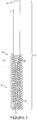
- a pipette assembly 10 which comprises a chamber 12 having an elongated body capable of holding and dispensing a liquid.
- Chamber 12 has an open proximal end 14 and an opposing distal end 16 that has a tapered tip 18 with a passageway 20 formed therethrough.
- One end of passageway 20 opens into chamber 12 to provide communication between the tip 18 and the chamber 12 and the opposing end of passageway 20 is open, such that liquid can pass therethrough and be dispensed through a cannula 22 that is coupled to tip 18.
- a biasing member 24 is provided, which is adapted such that one (top) end of the spring element is situated around the diameter of pipette assembly 10 ( e.g., around tip 18, as illustrated), encircling the diameter of the pipette assembly, and extending vertically downward.
- the top of the spring element is vertically aligned with or below the intersection of the distal end 16 of chamber 12 and the tip 18.
- spring element 24 has a diameter at the top ( i.e., at the position situated around the diameter of the tip 18 ) that is equal to or smaller than the diameter of the chamber 12, such that the diameter of the spring at the top is equal to the diameter of some portion of the tapered tip 18.
- the intersection of the distal end 16 of chamber 12 and the tip 18 is functionalized with a restraining mechanism (e.g., a raised line or groove around the circumference of the intersection) to prevent the top of spring element 24 from extending above the intersection.
- the top of the spring element 24 may be associated with the pipette assembly in another fashion.
- it may encircle the diameter of the chamber 12 at any position thereon, including at the top thereof ( e.g., at or close to open proximal end 14 ).
- chamber 12 can comprise a raised feature at or near the distal end 16 that renders the diameter of the chamber at that raised position greater than that of the diameter at the top of the spring.
- either the chamber 12 or the tip 18 comprises a groove or other structure within which the top of the spring can sit. Consequently, in such embodiments, when the pipette assembly 10 is equipped with a spring element 24, the top of the spring will not be vertically displaced when the spring is compressed upwards under typical forces.
- the top of the spring may be attached or unattached to the point at which it contacts the remainder of the pipette assembly. Any method for attachment can be used to associate the spring element 24 with the pipette assembly, including but not limited to, use of an adhesive or fastener associated with the spring element and/or the pipette assembly.
- the spring element can be press fit to the pipette-to-instrument fitting.
- the top of spring 10 is advantageously (temporarily or permanently) affixed or connected to the pipette assembly in some fashion such that, when the bottom of cannula 22 is not resting on a surface, the spring 10 remains associated with the pipette assembly (and does not slide off the pipette assembly when held in position vertically).
- the length of the spring element associated with the pipette assembly in uncompressed form can vary and can be dependent upon the point of contact between the pipette assembly and the top of the spring. The length is also dependent on the depth of the container to be filled using the pipette assembly.
- One important feature in preferred embodiments is that, regardless of the spring length, the bottom end of the uncompressed spring is generally horizontally disposed at some position along the length of cannula 22. The position of the bottom end of the uncompressed spring in combination with the compressibility of the spring is an important consideration for the function of the pipette assembly in the context of a large-scale automated instrument.
- the bottom end of spring element 24 is vertically displaceable by vertical compression of the spring upwards when the bottom end of spring element 24 comes into contact with resistance.
- the bottom of the spring in certain embodiments, is designed to come into contact with resistance at the top surface of the container into which liquid is to be dispensed. Accordingly, when the pipette assembly is employed, the cannula 22 extends into the container; spring element 24 engages the top diameter of the container, becoming compressed as the pipette assembly is moved vertically downwards.
- the diameter of the bottom of the spring element that comes into contact with the container must be sized such that the inner diameter of the spring element is comparable to that that of the container to ensure that the spring rests on top of the container, resulting in compression of the spring upwards when the spring element contacts the container.
- the bottom of spring element 24 may, in some embodiments, be modified through the addition of a restraining component.
- the restraining component can be any element affixed to the bottom of the spring element that changes the inner and/or outer diameter of the bottom end of the spring element.
- the restraining component is a washer of a particular diameter attached to the bottom of the spring, where the inner diameter of washer chosen to ensure washer-to-container engagement.
- the restraining component can be roughly circular, it is noted that other shapes can be employed to serve the desired function (e.g., rectangular, square, triangular, oval, etc.), so long as the dimensions of the restraining component are such that component-to-container engagement is achieved and the spring element is prevented from entering or surrounding the diameter of the container to be filled.
- the makeup of the spring element itself can vary. Generally, any spring meeting the requirements described herein can be used. Springs are generally metal (e.g., stainless steel), although other materials can be used in place of or in combination with the metal. Springs are typically cylindrically shaped and are commonly composed of a single wire wrapped in a helical and/or coiled fashion. The composition of the spring as well as the thickness and number of coils, among other parameters, can be modified to achieve a desired spring constant. The spring constant, in combination with the length to which the spring is compressed, provides the force of the spring (according to Hooke's law, which states that the force needed to extend or compress a spring by a distance X is equivalent to kX, where k is the "spring constant").
- the force for a given application as described herein is that at least that force needed to overcome the friction encountered by the cannula in the container to be filled.
- the force of the spring exceeds the friction force encountered by the cannula in the container to be filled and can be, for example, between about 2.1 g and about 2.5 g in certain embodiments.
- the desired force can be achieved by tailoring one or both of the distance travelled by the spring upon compression and the spring constant ( e.g., by changing the composition, number of coils, or thickness of the spring or by changing the vertical position of the end of spring 24 on the pipette assembly relative to the cannula) to achieve the goals stated herein.
- Spring elements as used herein are of sufficient diameter to encircle the pipette assembly.
- the diameter of the spring can be chosen such that the spring can be press fit to the pipette-to-instrument fitting.
- the diameter of the spring can, in some embodiments, be consistent or may be variable down the length of the spring ( e.g., with smaller or larger top and/or bottom end).
- the present disclosure also provides an automated liquid handling instrument comprising one or more pipette assemblies comprising a spring mechanism as detailed above.
- Various liquid handling instruments are known and can be modified by the incorporation of a spring element as described herein.
- a schematic representation of one such instrument 30 is provided in FIG. 2 , wherein the pipette assemblies 10 of the instrument can be modified by the association of a spring element therewith as described in the present disclosure.
- such instruments comprise an essentially horizontally oriented work surface 34 for the placement of containers; a liquid handling arm 32, equipped with at least one pipette assembly 10 for aspirating and dispensing a liquid (including at least one pipette modified as described herein); and a controller 36 to which the liquid handling arm is electrically connected, which controls operation of the instrument, including movement of the liquid handling arm and dispensing of liquid through the pipette assemblies.
- the number of pipette assemblies can vary.
- instruments are provided that comprise, e.g., four, six, eight, ten, or twelve aligned pipette assemblies in a single line.
- the liquid handling arm is equipped with a two-dimensional arrangement of pipette assemblies (e.g., in a 4 ⁇ 4 arrangement, 4 ⁇ 8 arrangement, 10 ⁇ 10 arrangement, 8 ⁇ 8 arrangement, 8 ⁇ 12 arrangement or 12 ⁇ 12 arrangement).
- the containers into which liquid is to be dispensed are the wells of microtiter trays or are containers that are held in trays such as those having 96 wells ( e.g., arranged as an 8 x 12 grid) or 384 wells ( e.g., arranged as a 16 x 24 grid).
- any instrument comprising any number and arrangement of pipette assemblies can be modified to associate biasing members therewith as described herein.
- Exemplary instruments include, but are not limited to, those disclosed in U.S. Patent Nos. 3,855,868 to Sudvaniemi ; 5,443,792 to Buhler ; 5,763,278 to Sickinger et al .; 6,627,160 to Wanner ; 6,780,381 to Yiu ; 6, 841,130 to Lehtinen et al .; 7,055,723 to Ingenhoven et al .; 7,964,160 to Zuppiger et al .; 8,580,197 to Glauser et al..
- the instruments described herein can be used for filling a wide range of containers with a wide range of liquids (e.g., including, but not limited to, pharmaceutical solutions, liquids for analytical analysis, and aerosol forming precursors for electronic smoking articles, etc.).
- the instruments described herein can be employed within an automated manufacturing system together with one or more other instruments, e.g., as described in U.S. Pat. App. 14/227,159 to Ampolini et al. .
- the liquid handling arm of a liquid handling instrument can iteratively dispense liquid from a series of pipette assemblies into one or more containers directly below (which can be, e.g., in aligned rows to correspond with the placement of the pipette assemblies on the liquid handling arm as shown in FIG. 2 ).
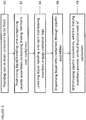
- FIG. 3 A schematic representation of typical method steps associated with use of a liquid handling instrument comprising pipette assemblies as described herein is provided in FIG. 3 .
- the method of use typically requires the step of providing one or more containers to be filled 40.
- Containers to be filled can vary in size and shape can comprise, for example, various types of vials, test tubes, cuvettes, wells, and cartridges.
- the liquid handling arm is positioned horizontally ( e.g., in the X and Y direction) 42 such that the pipette assemblies associated therewith are aligned over the containers to be filled.
- the liquid handling arm then is lowered vertically downward 44 such that at least a portion of cannula 22 is within the container to be filled.
- Liquid is dispensed 46 into each container through the pipette assemblies.
- the liquid handling arm is then moved vertically upwards, such that the pipette assemblies are withdrawn vertically upwards from the containers 48.
- the liquid handling arm then can optionally move horizontally to dispense liquid into a second plurality of containers directly below. These steps can be repeated until the desired number of containers on the work surface 34 are filled.
- the spring element associated with the pipette assemblies described herein remains associated with the pipette assembly and moves vertically with the handling arm, such that bottom end of spring element 24 (or a restraining component associated therewith) comes into contact with the containers prior to the dispensing of liquid into the containers.
- bottom end of spring element 24 comes into contact with the container, any further vertical downward movement of the liquid handling arm (to ensure the cannula end is at the desired level within the container for dispensing of the liquid) results in compression of spring element 24 upwards toward the liquid handling arm.
- the pipette assemblies provided according to the present disclosure are particularly beneficial in filing containers comprising one or more solid or semi-solid materials, such as reservoir-containing cartridges, as will be described in greater detail below.
- the containers to be filled comprise a solid or semi-solid material
- the cannula used to fill the container generally experiences some friction when it comes into contact with that material, which must be overcome to dispense the liquid and to withdraw the cannula 22 from the container.
- the containers are cartridges to be employed within aerosol-generating devices, such as electronic smoking articles.
- the term “cartridge” refers to a container, receptacle or chamber for holding, storing, or retaining a product such as a liquid, fluid, or aerosol. Certain such cartridges are described in U.S. Pat. App. Nos. 14/286,552 to Brinkley et al. and 13,841,233 to DePiano et al. , U.S. Pat. App. Pub. Nos. 2014/0060555 to Chang et al. and 2014/0000638 to Sebastian et al. , and U.S. Patent No. 7,726,320 to Robinson et al. For example, FIG.
- the reservoir 4 provides a cut-away view of a cartridge 500 that can be included in an electronic smoking article, including a reservoir 501.
- the reservoir 501 may advantageously have a diameter such that the exterior surface 505 of the reservoir can be adapted to fit within and conform to an interior surface 506 of cartridge walls 502.
- the reservoir is designed to retain a liquid, fluid, or aerosol within the cartridge walls 502 ( e.g., wherein an aerosol precursor composition can be sorptively retained by the reservoir layer 501 ).
- the reservoir layer 501 can be in fluid connection with a transport element that can transport an aerosol precursor composition stored in the reservoir layer 501 via capillary action to an aerosolization zone.
- the reservoir 501 can be e.g., fibrous and can comprise, in some embodiments, cellulose acetate. If desired, the reservoir can comprise a binder. Fillers (e.g., cellulose) and fibers formed of different materials also can be used.
- the reservoir can comprise about 70% to about 99% by weight cellulose acetate fibers, and the weights noted herein are measured on a dry weight basis. More specifically, the reservoir can comprise about 75% to about 98%, about 80% to about 97.5%, or about 90% to about 97% by weight cellulose acetate fibers.
- the reservoir can comprise about 1% to about 30% by weight of the binder.
- the reservoir can comprise about 2% to about 25%, about 2.5% to about 20%, or about 3% to about 10% by weight of the binder.
- a reservoir according to the disclosure can comprise about 95% to about 97% by weight cellulose acetate fiber and about 3% to about 5% by weight binder.
- a reservoir according to the disclosure can comprise about 80% to about 85% by weight cellulose acetate fiber and about 15% to about 20% by weight binder.
- a binder is understood to be a material that imparts a cohesive effect to the fibers used in forming the disclosed reservoirs.
- the binder can be a material that partially solubilizes the cellulose acetate fibers such that the fibers bind to each other or to further fibrous materials included in the woven or non-woven reservoir.
- binders that can be used include polyvinyl acetate (PVA) binders, starch, and triacetin.
- the pipette assemblies described herein can extend into the reservoir material and dispense an aerosol precursor composition (e.g., commonly a liquid capable of yielding an aerosol upon application of sufficient heat, such as ingredients commonly referred to as "smoke juice,” “e-liquid” and “e-juice”) within the cartridge, such that at least a portion of the composition can be sorptively retained by the reservoir.
- an aerosol precursor composition e.g., commonly a liquid capable of yielding an aerosol upon application of sufficient heat, such as ingredients commonly referred to as "smoke juice,” “e-liquid” and “e-juice
- the biasing member described herein allows the cannula 22 to penetrate the reservoir material and yet be effectively withdrawn therefrom following dispensing, with little to no vertical displacement of the cartridge upon the vertically upward withdrawal of the cannula.
- a cartridge is provided that comprises a reservoir in an outer component of the cartridge.
- the cannula may remain out of contact with the reservoir substrate.
- the cannula may contact at least a portion of the reservoir substrate and/or may contact the top, wall, or bottom of the container ( e.g., the cartridge).
- the pipette assembly can be lowered into the cartridge or container to be filled, which may be initially aligned such that its longitudinal axis is vertical or substantially vertical.
- the pipette assembly can then be moved sideways (within the horizontal plane) such that a portion of the pipette assembly contacts a portion of the cartridge or container (e.g., the top lip and/or a wall of the cartridge or container), causing the longitudinal axis of the cartridge or container to be tilted with respect to the vertical plane.
- the cartridge or container may be tilted at an angle of between about 5 and about 45 degrees with respect to the vertical plane. Following this tilting, the liquid to be dispensed can then be directed down an inner surface of the cartridge or container wall(s).
- the spring assembly associated with the pipette assembly can serve to overcome friction associated with penetration of the reservoir substrate and/or friction associated with contact between the cannula and the cartridge itself ( e.g., a wall of the cartridge).
Landscapes
- Engineering & Computer Science (AREA)
- Mechanical Engineering (AREA)
- Health & Medical Sciences (AREA)
- Chemical & Material Sciences (AREA)
- Clinical Laboratory Science (AREA)
- Chemical Kinetics & Catalysis (AREA)
- Analytical Chemistry (AREA)
- Life Sciences & Earth Sciences (AREA)
- Physics & Mathematics (AREA)
- Biochemistry (AREA)
- General Health & Medical Sciences (AREA)
- General Physics & Mathematics (AREA)
- Immunology (AREA)
- Pathology (AREA)
- Feeding, Discharge, Calcimining, Fusing, And Gas-Generation Devices (AREA)
- Basic Packing Technique (AREA)
- Apparatus Associated With Microorganisms And Enzymes (AREA)
Claims (17)
- Eine Pipettenanordnung, umfassend eine Kammer (12) mit einem länglichen Körper, in welcher eine Flüssigkeit aufnehmbar ist, wobei die Kammer (12) ein proximales Ende (14) zum Einbringen der Flüssigkeit und ein gegenüberliegendes distales Ende (16) in Fluidverbindung mit einer Kanüle (22) zum Dispensieren der Flüssigkeit in einen Behälter umfasst, ferner umfassend ein Vorspannglied (24), welches mindestens einen Teil der Pipettenanordnung umgibt und diesem zugeordnet ist, dadurch gekennzeichnet, dass das Vorspannglied (24) ausgebildet ist, eine temporäre Vorspannkraft zwischen der Pipettenanordnung und der Oberseite eines zu befüllenden Behälters anzulegen, um eine Aufwärtsbewegung des Behälters beim Entfernen der Pipettenanordnung von dem Behälter zu vermeiden.
- Die Pipettenanordnung nach Anspruch 1, wobei das Vorspannglied (24) zeitweilig oder dauerhaft mit der Pipettenanordnung verbunden ist.
- Die Pipettenanordnung nach Anspruch 1 oder 2, wobei das Vorspannglied (24) eine gewundene Feder umfasst und wobei insbesondere die gewundene Feder Edelstahl umfasst.
- Die Pipettenanordnung nach einem der Ansprüche 1 bis 3, wobei die Kompressionskraft des Vorspanngliedes (24) zwischen ungefähr 20,6 mN (2,1 g) und ungefähr 25 mN (2,5 g) liegt.
- Die Pipettenanordnung nach einem der Ansprüche 1 bis 4, wobei das Vorspannglied (24) ferner an seinem unteren Ende eine Rückhaltekomponente umfasst, welche den Durchmesser des unteren Endes des Vorspanngliedes (24) modifiziert, und wobei insbesondere die Rückhaltekomponente eine Metallunterlegscheibe umfasst.
- Ein Flüssigkeitshandhabungsinstrument zum Dispensieren von Flüssigkeitsproben, umfassend einen beweglichen Flüssigkeitshandhabungsarm (32), umfassend mindestens eine Pipettenanordnung (10) nach einem der Ansprüche 1 bis 5 und eine Kontrolleinrichtung (36), mit welcher der Flüssigkeitshandhabungsarm (32) elektrisch verbunden ist.
- Das Flüssigkeitshandhabungsinstrument nach Anspruch 6, wobei der Behälter ein festes oder halbfestes Material umfasst und die Kompressionskraft des Vorspanngliedes mindestens derjenigen entspricht, die erforderlich ist, damit die Kanüle (22) das feste oder halbfeste Material durchdringt.
- Ein Verfahren zum Dispensieren einer Flüssigkeit in einen Behälter, umfassend:Bereitstellen eines beweglichen Flüssigkeitshandhabungsarms (32), umfassend mindestens eine Pipettenanordnung (10) und eine Kontrolleinrichtung (36), mit welcher der Flüssigkeitshandhabungsarm (32) elektrisch verbunden ist, wobei die mindestens eine Pipettenanordnung (10) eine Kammer (12) mit einem länglichen Körper umfasst, in welcher eine Flüssigkeit aufnehmbar ist, wobei die Kammer (12) ein proximales Ende (14) zum Einbringen der Flüssigkeit und ein gegenüberliegendes distales Ende (16) in Fluidverbindung mit einer Kanüle (22) zum Dispensieren der Flüssigkeit in einen Behälter umfasst, ferner umfassend ein Vorspannglied (24), welches mindestens einen Teil der Pipettenanordnung (10) umgibt und diesem zugeordnet ist,Bereitstellen eines oder mehrerer Behälter, welche zu füllen sind;horizontales Positionieren des beweglichen Flüssigkeitshandhabungsarms (32), derart, dass jeweils ein Behälter vertikal unterhalb einer jeden Pipettenanordnung (10) angeordnet ist;vertikales Absenken der Pipettenanordnung (10), derart, dass sich die Kanüle (22) der Pipettenanordnung (10) innerhalb des Behälters befindet, wobei das Vorspannglied (24) auf der Oberseite des Behälters aufliegt und zusammengedrückt ist;Dispensieren der Flüssigkeit in den Behälter; undAbziehen der Pipettenanordnung (10) von dem Behälter, dadurch gekennzeichnet, dass das Vorspannglied (24) verhindert, dass der Behälter beim nach oben gerichteten Abziehen der Pipettenanordnung (10) von dem Behälter vertikal verschoben wird.
- Das Verfahren nach Anspruch 8, wobei die Behälter ein festes oder halbfestes Material umfassen und die Kompressionskraft des Vorspanngliedes (24) mindestens derjenigen entspricht, die erforderlich ist, damit die Kanüle (22) das feste oder halbfeste Material durchdringt, und wobei insbesondere das feste oder halbfeste Material ein faseriges Material umfasst und wobei insbesondere das feste oder halbfeste Material Celluloseacetat umfasst.
- Das Verfahren nach Anspruch 8 oder 9, wobei die Behälter in Form von Patronen (500) für elektronische Rauchartikel vorliegen und wobei insbesondere die Patronen (500) faserige Reservoirs (501) umfassen und wobei insbesondere die Flüssigkeit eine Aerosol-Precursor-Zusammensetzung umfasst.
- Das Verfahren nach Anspruch 10, ferner umfassend: Schrägstellen der Patrone (500) vor dem Schritt des Dispensierens, derart, dass die Patrone (500) in einem Winkel zwischen ungefähr 5 und 45 Grad bezüglich der vertikalen Ebene steht.
- Das Verfahren nach Anspruch 10 oder 11, wobei während des Schrittes des Dispensierens die Kanüle (22) mit einer oder beiden der Komponenten, welche sind das faserige Reservoir (501) und die Patrone (500), in Kontakt steht und wobei insbesondere die Kompressionskraft des Vorspanngliedes (24) mindestens derjenigen entspricht, die erforderlich ist, damit die Kanüle (22) die Reibung überwindet, die mit dem Kontakt mit einer oder beiden der Komponenten, welche sind das faserige Reservoir (501) und die Patrone (500), verbunden ist.
- Das Verfahren nach einem der Ansprüche 10 bis 12, wobei das faserige Reservoir (501) Celluloseacetat umfasst.
- Das Verfahren nach einem der Ansprüche 8 bis 13, wobei die Kompressionskraft des Vorspanngliedes zwischen ungefähr 20,6 mN (2,1 g) und ungefähr 25 mN (2,5 g) liegt.
- Das Verfahren nach einem der Ansprüche 8 bis 14, wobei das Vorspannglied (24) zeitweilig oder dauerhaft mit der Pipettenanordnung (10) verbunden ist.
- Das Verfahren nach einem der Ansprüche 8 bis 15, wobei das Vorspannglied (24) eine gewundene Feder umfasst und wobei insbesondere die gewundene Feder Edelstahl umfasst.
- Das Verfahren nach einem der Ansprüche 8 bis 16, wobei das Vorspannglied (24) ferner an seinem unteren Ende eine Rückhaltekomponente umfasst, welche den Durchmesser des unteren Endes des Vorspanngliedes (24) modifiziert, und wobei insbesondere die Rückhaltekomponente eine Metallunterlegscheibe umfasst.
Priority Applications (1)
| Application Number | Priority Date | Filing Date | Title |
|---|---|---|---|
| PL15756279T PL3183174T3 (pl) | 2014-08-20 | 2015-08-13 | Układ do pipetowania |
Applications Claiming Priority (2)
| Application Number | Priority Date | Filing Date | Title |
|---|---|---|---|
| US14/464,078 US9927452B2 (en) | 2014-08-20 | 2014-08-20 | Pipetting system |
| PCT/US2015/045039 WO2016028598A1 (en) | 2014-08-20 | 2015-08-13 | Pipetting system |
Publications (2)
| Publication Number | Publication Date |
|---|---|
| EP3183174A1 EP3183174A1 (de) | 2017-06-28 |
| EP3183174B1 true EP3183174B1 (de) | 2018-06-06 |
Family
ID=54011086
Family Applications (1)
| Application Number | Title | Priority Date | Filing Date |
|---|---|---|---|
| EP15756279.4A Active EP3183174B1 (de) | 2014-08-20 | 2015-08-13 | Pipettiersystem |
Country Status (6)
| Country | Link |
|---|---|
| US (1) | US9927452B2 (de) |
| EP (1) | EP3183174B1 (de) |
| JP (2) | JP6925263B2 (de) |
| CN (1) | CN107073473B (de) |
| PL (1) | PL3183174T3 (de) |
| WO (1) | WO2016028598A1 (de) |
Cited By (1)
| Publication number | Priority date | Publication date | Assignee | Title |
|---|---|---|---|---|
| US11424633B2 (en) | 2018-10-08 | 2022-08-23 | Juul Labs, Inc. | Vaporizer charging adapter assembly |
Families Citing this family (9)
| Publication number | Priority date | Publication date | Assignee | Title |
|---|---|---|---|---|
| US10611505B2 (en) * | 2015-05-04 | 2020-04-07 | Rai Strategic Holdings, Inc. | Dispensing machine for aerosol precursor |
| US10238145B2 (en) | 2015-05-19 | 2019-03-26 | Rai Strategic Holdings, Inc. | Assembly substation for assembling a cartridge for a smoking article |
| US10405579B2 (en) | 2016-04-29 | 2019-09-10 | Rai Strategic Holdings, Inc. | Methods for assembling a cartridge for an aerosol delivery device, and associated systems and apparatuses |
| US10759554B2 (en) | 2017-02-02 | 2020-09-01 | Rai Strategic Holdings, Inc. | Dispenser unit for aerosol precursor |
| IT201800005755A1 (it) | 2018-05-28 | 2019-11-28 | Apparecchiatura e procedimento per inserire automaticamente un liquido all’interno di componenti di inalatori, in particolare cartomizzatori per sigarette elettroniche. | |
| US12279647B2 (en) | 2019-12-23 | 2025-04-22 | Pax Labs, Inc. | Vaporizer cartridge |
| USD1028336S1 (en) | 2021-06-22 | 2024-05-21 | Pax Labs, Inc. | Vaporizer cartridge |
| DE102022101820A1 (de) * | 2022-01-26 | 2023-07-27 | Atec Pharmatechnik Gmbh | Transfer-Port zum Übertragen eines Fluides sowie Übertragungs-System |
| GB202308144D0 (en) * | 2023-05-31 | 2023-07-12 | Nicoventures Trading Ltd | Apparatus for dispensing fluid into components of a delivery system |
Family Cites Families (51)
| Publication number | Priority date | Publication date | Assignee | Title |
|---|---|---|---|---|
| US2877813A (en) * | 1957-07-01 | 1959-03-17 | Reich & Sons Inc A | Filling valve assembly for canning machine |
| US3707174A (en) | 1970-12-30 | 1972-12-26 | Diehl Mateer Co G | Apparatus for filling containers |
| GB1392791A (en) | 1972-02-10 | 1975-04-30 | Suovaniemi Oa | Multiple pipette |
| US3991627A (en) * | 1975-11-28 | 1976-11-16 | Block Engineering, Inc. | Alignment device for sample containers |
| JPS6122799U (ja) * | 1984-07-13 | 1986-02-10 | 澁谷工業株式会社 | 充填装置 |
| US4713974A (en) * | 1986-04-18 | 1987-12-22 | Varian Associates, Inc./Scientific Systems, Inc. | Autosampler |
| JPH01501294A (ja) * | 1986-12-17 | 1989-05-11 | マイクローボル・リミテッド | 加圧計量分配容器 |
| CA2017111C (en) * | 1989-06-01 | 1995-10-31 | Andreas Greter | Pipetting insert |
| EP0555739B1 (de) | 1992-02-13 | 1998-05-20 | F. Hoffmann-La Roche Ag | Automatische Pipettiervorrichtung |
| JPH06265448A (ja) * | 1993-03-15 | 1994-09-22 | Hitachi Ltd | 液体供給装置 |
| EP0733404A1 (de) * | 1995-03-24 | 1996-09-25 | Becton, Dickinson and Company | Pipettenspitze |
| JP3512526B2 (ja) * | 1995-06-30 | 2004-03-29 | アークレイ株式会社 | 検体吸引装置 |
| US5763278A (en) | 1995-11-01 | 1998-06-09 | Tecan Ag | Automated pipetting of small volumes |
| US5915284A (en) * | 1996-07-22 | 1999-06-22 | Cyberlab, Inc. | Multiple channel pipetting device |
| JP3687019B2 (ja) * | 1996-10-16 | 2005-08-24 | アークレイ株式会社 | サンプリング装置 |
| DE19835833A1 (de) | 1998-08-07 | 2000-02-17 | Max Planck Gesellschaft | Dosierkopf zur parallelen Bearbeitung einer Vielzahl von Fluidproben |
| US6270726B1 (en) | 1999-09-30 | 2001-08-07 | Dpc Cirrus, Inc. | Tube bottom sensing for small fluid samples |
| ATE289872T1 (de) | 1999-10-21 | 2005-03-15 | Tecan Trading Ag | Abgabe- bzw. pipettiereinrichtung mit auswechselbarer pipettenspitze |
| DE10013511A1 (de) | 2000-03-20 | 2001-10-11 | Brand Gmbh & Co Kg | Mehrkanal-Pipettiereinrichtung sowie Pipettenschaft dafür |
| WO2002040165A1 (de) | 2000-11-17 | 2002-05-23 | Tecan Trading Ag | Vorrichtung und system zur abgabe bzw. aufnahme/abgabe von flüssigkeitsproben |
| FI20002761A0 (fi) | 2000-12-15 | 2000-12-15 | Wallac Oy | Monikanavainen pipetointilaitteisto |
| DE20212722U1 (de) | 2001-01-26 | 2002-10-24 | Tecan Trading Ag, Baar | Haltevorrichtung |
| DE10111470A1 (de) * | 2001-03-09 | 2002-09-12 | Hilti Ag | Unterlegscheibe für chemische Anker |
| US6652378B2 (en) | 2001-06-01 | 2003-11-25 | Igt | Gaming machines and systems offering simultaneous play of multiple games and methods of gaming |
| US6780381B2 (en) | 2002-04-08 | 2004-08-24 | Felix H. Yiu | Pipettor and externally sealed pipette tip |
| US20040071602A1 (en) | 2002-10-15 | 2004-04-15 | Yiu Felix H. | Pipettor head adapter |
| WO2005011832A2 (en) * | 2003-07-29 | 2005-02-10 | Sullivan James J | A simultaneous multi-colum liquid chromatograph for direct sampling of an array of liquid samples |
| CA2487192A1 (en) * | 2004-11-05 | 2006-05-05 | Ll Lafond Intellectual Properties Inc. | Dispensing device with secondary reservior |
| DE202006010293U1 (de) | 2005-07-22 | 2006-08-31 | Tecan Trading Ag | Pipettiergerät mit Computerprogrammprodukt zum Akzeptieren oder Verwerfen von pipettierten Flüssigkeitsproben |
| JP2007093537A (ja) * | 2005-09-30 | 2007-04-12 | Yaskawa Electric Corp | 液体試料分注装置 |
| US7726320B2 (en) | 2006-10-18 | 2010-06-01 | R. J. Reynolds Tobacco Company | Tobacco-containing smoking article |
| CN101178467A (zh) * | 2006-11-08 | 2008-05-14 | 鸿富锦精密工业(深圳)有限公司 | 点胶装置 |
| EP2772532B1 (de) * | 2008-03-12 | 2023-06-21 | Cellectricon Ab | Vorrichtung und Verfahren zur Spitzenausrichtung auf Multiwellplatten |
| WO2009130318A2 (en) | 2008-04-24 | 2009-10-29 | Tecan Trading Ag | Direct pipetting in computer-controlled liquid handling workstations |
| US8468900B2 (en) * | 2010-05-03 | 2013-06-25 | Integra Biosciences Corp. | Pipette tip positioning for manually-directed, multi-channel electronic pipettor |
| JPWO2012070107A1 (ja) * | 2010-11-22 | 2014-05-19 | 株式会社元林 | 電子たばこ用液体補充具 |
| US20120199118A1 (en) | 2011-02-04 | 2012-08-09 | Piramal Critical Care, Inc. | Bottle closure with hinged seal |
| US8528569B1 (en) | 2011-06-28 | 2013-09-10 | Kyle D. Newton | Electronic cigarette with liquid reservoir |
| JP5792528B2 (ja) * | 2011-06-29 | 2015-10-14 | 靜甲株式会社 | 液体充填装置および液体充填方法 |
| DE102011108537B4 (de) | 2011-07-26 | 2023-10-12 | Eppendorf Se | Positioniereinrichtung für eine Laborvorrichtung zum Verteilen fluider Proben und Laborvorrichtung mit Positioniereinrichtung |
| JP5752545B2 (ja) | 2011-09-22 | 2015-07-22 | 株式会社日立ハイテクノロジーズ | 自動分析装置 |
| US10004259B2 (en) | 2012-06-28 | 2018-06-26 | Rai Strategic Holdings, Inc. | Reservoir and heater system for controllable delivery of multiple aerosolizable materials in an electronic smoking article |
| US8910639B2 (en) | 2012-09-05 | 2014-12-16 | R. J. Reynolds Tobacco Company | Single-use connector and cartridge for a smoking article and related method |
| US9086394B2 (en) | 2012-10-24 | 2015-07-21 | Accel Biotech, Inc. | Multi-function dispense head |
| US8910640B2 (en) | 2013-01-30 | 2014-12-16 | R.J. Reynolds Tobacco Company | Wick suitable for use in an electronic smoking article |
| US20140261487A1 (en) | 2013-03-14 | 2014-09-18 | R. J. Reynolds Tobacco Company | Electronic smoking article with improved storage and transport of aerosol precursor compositions |
| US9220302B2 (en) | 2013-03-15 | 2015-12-29 | R.J. Reynolds Tobacco Company | Cartridge for an aerosol delivery device and method for assembling a cartridge for a smoking article |
| CN103586095B (zh) * | 2013-11-26 | 2015-07-01 | 东南大学 | 多通道移液器 |
| CN203635231U (zh) * | 2013-12-26 | 2014-06-11 | 合肥知常光电科技有限公司 | 一种移液器用枪尖结构 |
| US20150216232A1 (en) | 2014-02-03 | 2015-08-06 | R.J. Reynolds Tobacco Company | Aerosol Delivery Device Comprising Multiple Outer Bodies and Related Assembly Method |
| US9955726B2 (en) | 2014-05-23 | 2018-05-01 | Rai Strategic Holdings, Inc. | Sealed cartridge for an aerosol delivery device and related assembly method |
-
2014
- 2014-08-20 US US14/464,078 patent/US9927452B2/en active Active
-
2015
- 2015-08-13 EP EP15756279.4A patent/EP3183174B1/de active Active
- 2015-08-13 PL PL15756279T patent/PL3183174T3/pl unknown
- 2015-08-13 CN CN201580056945.8A patent/CN107073473B/zh active Active
- 2015-08-13 WO PCT/US2015/045039 patent/WO2016028598A1/en not_active Ceased
- 2015-08-13 JP JP2017509664A patent/JP6925263B2/ja active Active
-
2021
- 2021-04-30 JP JP2021077604A patent/JP2021175681A/ja active Pending
Non-Patent Citations (1)
| Title |
|---|
| None * |
Cited By (2)
| Publication number | Priority date | Publication date | Assignee | Title |
|---|---|---|---|---|
| US11424633B2 (en) | 2018-10-08 | 2022-08-23 | Juul Labs, Inc. | Vaporizer charging adapter assembly |
| US12149109B2 (en) | 2018-10-08 | 2024-11-19 | Juul Labs, Inc. | Vaporizer charging adapter assembly |
Also Published As
| Publication number | Publication date |
|---|---|
| JP6925263B2 (ja) | 2021-08-25 |
| CN107073473A (zh) | 2017-08-18 |
| US20160054345A1 (en) | 2016-02-25 |
| JP2021175681A (ja) | 2021-11-04 |
| JP2017526587A (ja) | 2017-09-14 |
| CN107073473B (zh) | 2020-04-28 |
| PL3183174T3 (pl) | 2018-11-30 |
| US9927452B2 (en) | 2018-03-27 |
| WO2016028598A1 (en) | 2016-02-25 |
| EP3183174A1 (de) | 2017-06-28 |
Similar Documents
| Publication | Publication Date | Title |
|---|---|---|
| US9927452B2 (en) | Pipetting system | |
| EP3009019B1 (de) | Patrone mit einem flüssigkeitstransportelement zur verwendung mit einer elektronischen rauchvorrichtung | |
| EP2979556A1 (de) | Zerstäuber und elektronische zigarette | |
| EP3195741A2 (de) | Elektronische zigarette | |
| EP3849354B1 (de) | Verbrauchsartikelhaltemechanismus | |
| EP2946679A1 (de) | Zerstäuber und damit ausgerüstete elektronische zigarette | |
| JP2019512257A (ja) | 電子ベイピング装置 | |
| RU2015148935A (ru) | Дозирование жидкостей и способы дозирования жидкостей | |
| WO2010102207A3 (en) | Tip arrangement for a dropper bottle | |
| IN2015DN01005A (de) | ||
| CN110584222A (zh) | 烟弹及烟具 | |
| EP3753595A1 (de) | Aerosolabgabevorrichtung | |
| US9591846B2 (en) | Apparatus and method for separating and storing human reproductive material in a cryotank | |
| EP2640339B1 (de) | Vorrichtung und verfahren zur sequestrierung von während eines flüssigkeitstransfers entwichenen flüssigkeiten | |
| WO2007084466A3 (en) | Erythrocyte sedimentation rate test measurement instrument | |
| CN211020998U (zh) | 烟弹及烟具 | |
| CN206996635U (zh) | 高通量移液器 | |
| CN111343931A (zh) | 尤其是用于过敏诊断的表面切割设备 | |
| EP4054417B1 (de) | Blutentnahmevorrichtung und verfahren zur selbstentnahme von blut durch einen benutzer | |
| CN205433713U (zh) | 一种血液采集存储器 | |
| CN204146308U (zh) | 一种香烟吸烟器 | |
| US9894929B2 (en) | Hookah | |
| CN103808594A (zh) | 分子筛吸附量的测定装置 | |
| CN208679186U (zh) | 一种食品检测用胶头滴管 | |
| CN212014428U (zh) | 一种新型香烟伴侣 |
Legal Events
| Date | Code | Title | Description |
|---|---|---|---|
| PUAI | Public reference made under article 153(3) epc to a published international application that has entered the european phase |
Free format text: ORIGINAL CODE: 0009012 |
|
| 17P | Request for examination filed |
Effective date: 20170222 |
|
| AK | Designated contracting states |
Kind code of ref document: A1 Designated state(s): AL AT BE BG CH CY CZ DE DK EE ES FI FR GB GR HR HU IE IS IT LI LT LU LV MC MK MT NL NO PL PT RO RS SE SI SK SM TR |
|
| AX | Request for extension of the european patent |
Extension state: BA ME |
|
| DAV | Request for validation of the european patent (deleted) | ||
| DAX | Request for extension of the european patent (deleted) | ||
| GRAP | Despatch of communication of intention to grant a patent |
Free format text: ORIGINAL CODE: EPIDOSNIGR1 |
|
| INTG | Intention to grant announced |
Effective date: 20171215 |
|
| GRAS | Grant fee paid |
Free format text: ORIGINAL CODE: EPIDOSNIGR3 |
|
| GRAA | (expected) grant |
Free format text: ORIGINAL CODE: 0009210 |
|
| AK | Designated contracting states |
Kind code of ref document: B1 Designated state(s): AL AT BE BG CH CY CZ DE DK EE ES FI FR GB GR HR HU IE IS IT LI LT LU LV MC MK MT NL NO PL PT RO RS SE SI SK SM TR |
|
| REG | Reference to a national code |
Ref country code: GB Ref legal event code: FG4D |
|
| REG | Reference to a national code |
Ref country code: CH Ref legal event code: EP Ref country code: AT Ref legal event code: REF Ref document number: 1005817 Country of ref document: AT Kind code of ref document: T Effective date: 20180615 |
|
| REG | Reference to a national code |
Ref country code: IE Ref legal event code: FG4D |
|
| REG | Reference to a national code |
Ref country code: DE Ref legal event code: R096 Ref document number: 602015012041 Country of ref document: DE |
|
| REG | Reference to a national code |
Ref country code: FR Ref legal event code: PLFP Year of fee payment: 4 |
|
| REG | Reference to a national code |
Ref country code: NL Ref legal event code: MP Effective date: 20180606 |
|
| REG | Reference to a national code |
Ref country code: LT Ref legal event code: MG4D |
|
| PG25 | Lapsed in a contracting state [announced via postgrant information from national office to epo] |
Ref country code: NO Free format text: LAPSE BECAUSE OF FAILURE TO SUBMIT A TRANSLATION OF THE DESCRIPTION OR TO PAY THE FEE WITHIN THE PRESCRIBED TIME-LIMIT Effective date: 20180906 Ref country code: ES Free format text: LAPSE BECAUSE OF FAILURE TO SUBMIT A TRANSLATION OF THE DESCRIPTION OR TO PAY THE FEE WITHIN THE PRESCRIBED TIME-LIMIT Effective date: 20180606 Ref country code: LT Free format text: LAPSE BECAUSE OF FAILURE TO SUBMIT A TRANSLATION OF THE DESCRIPTION OR TO PAY THE FEE WITHIN THE PRESCRIBED TIME-LIMIT Effective date: 20180606 Ref country code: CY Free format text: LAPSE BECAUSE OF FAILURE TO SUBMIT A TRANSLATION OF THE DESCRIPTION OR TO PAY THE FEE WITHIN THE PRESCRIBED TIME-LIMIT Effective date: 20180606 Ref country code: SE Free format text: LAPSE BECAUSE OF FAILURE TO SUBMIT A TRANSLATION OF THE DESCRIPTION OR TO PAY THE FEE WITHIN THE PRESCRIBED TIME-LIMIT Effective date: 20180606 Ref country code: FI Free format text: LAPSE BECAUSE OF FAILURE TO SUBMIT A TRANSLATION OF THE DESCRIPTION OR TO PAY THE FEE WITHIN THE PRESCRIBED TIME-LIMIT Effective date: 20180606 Ref country code: BG Free format text: LAPSE BECAUSE OF FAILURE TO SUBMIT A TRANSLATION OF THE DESCRIPTION OR TO PAY THE FEE WITHIN THE PRESCRIBED TIME-LIMIT Effective date: 20180906 |
|
| PG25 | Lapsed in a contracting state [announced via postgrant information from national office to epo] |
Ref country code: RS Free format text: LAPSE BECAUSE OF FAILURE TO SUBMIT A TRANSLATION OF THE DESCRIPTION OR TO PAY THE FEE WITHIN THE PRESCRIBED TIME-LIMIT Effective date: 20180606 Ref country code: LV Free format text: LAPSE BECAUSE OF FAILURE TO SUBMIT A TRANSLATION OF THE DESCRIPTION OR TO PAY THE FEE WITHIN THE PRESCRIBED TIME-LIMIT Effective date: 20180606 Ref country code: GR Free format text: LAPSE BECAUSE OF FAILURE TO SUBMIT A TRANSLATION OF THE DESCRIPTION OR TO PAY THE FEE WITHIN THE PRESCRIBED TIME-LIMIT Effective date: 20180907 Ref country code: HR Free format text: LAPSE BECAUSE OF FAILURE TO SUBMIT A TRANSLATION OF THE DESCRIPTION OR TO PAY THE FEE WITHIN THE PRESCRIBED TIME-LIMIT Effective date: 20180606 |
|
| REG | Reference to a national code |
Ref country code: AT Ref legal event code: MK05 Ref document number: 1005817 Country of ref document: AT Kind code of ref document: T Effective date: 20180606 |
|
| PG25 | Lapsed in a contracting state [announced via postgrant information from national office to epo] |
Ref country code: NL Free format text: LAPSE BECAUSE OF FAILURE TO SUBMIT A TRANSLATION OF THE DESCRIPTION OR TO PAY THE FEE WITHIN THE PRESCRIBED TIME-LIMIT Effective date: 20180606 |
|
| PG25 | Lapsed in a contracting state [announced via postgrant information from national office to epo] |
Ref country code: SK Free format text: LAPSE BECAUSE OF FAILURE TO SUBMIT A TRANSLATION OF THE DESCRIPTION OR TO PAY THE FEE WITHIN THE PRESCRIBED TIME-LIMIT Effective date: 20180606 Ref country code: EE Free format text: LAPSE BECAUSE OF FAILURE TO SUBMIT A TRANSLATION OF THE DESCRIPTION OR TO PAY THE FEE WITHIN THE PRESCRIBED TIME-LIMIT Effective date: 20180606 Ref country code: IS Free format text: LAPSE BECAUSE OF FAILURE TO SUBMIT A TRANSLATION OF THE DESCRIPTION OR TO PAY THE FEE WITHIN THE PRESCRIBED TIME-LIMIT Effective date: 20181006 Ref country code: AT Free format text: LAPSE BECAUSE OF FAILURE TO SUBMIT A TRANSLATION OF THE DESCRIPTION OR TO PAY THE FEE WITHIN THE PRESCRIBED TIME-LIMIT Effective date: 20180606 Ref country code: RO Free format text: LAPSE BECAUSE OF FAILURE TO SUBMIT A TRANSLATION OF THE DESCRIPTION OR TO PAY THE FEE WITHIN THE PRESCRIBED TIME-LIMIT Effective date: 20180606 Ref country code: CZ Free format text: LAPSE BECAUSE OF FAILURE TO SUBMIT A TRANSLATION OF THE DESCRIPTION OR TO PAY THE FEE WITHIN THE PRESCRIBED TIME-LIMIT Effective date: 20180606 |
|
| PG25 | Lapsed in a contracting state [announced via postgrant information from national office to epo] |
Ref country code: SM Free format text: LAPSE BECAUSE OF FAILURE TO SUBMIT A TRANSLATION OF THE DESCRIPTION OR TO PAY THE FEE WITHIN THE PRESCRIBED TIME-LIMIT Effective date: 20180606 |
|
| REG | Reference to a national code |
Ref country code: DE Ref legal event code: R097 Ref document number: 602015012041 Country of ref document: DE |
|
| PG25 | Lapsed in a contracting state [announced via postgrant information from national office to epo] |
Ref country code: MC Free format text: LAPSE BECAUSE OF FAILURE TO SUBMIT A TRANSLATION OF THE DESCRIPTION OR TO PAY THE FEE WITHIN THE PRESCRIBED TIME-LIMIT Effective date: 20180606 |
|
| REG | Reference to a national code |
Ref country code: CH Ref legal event code: PL |
|
| PLBE | No opposition filed within time limit |
Free format text: ORIGINAL CODE: 0009261 |
|
| STAA | Information on the status of an ep patent application or granted ep patent |
Free format text: STATUS: NO OPPOSITION FILED WITHIN TIME LIMIT |
|
| PG25 | Lapsed in a contracting state [announced via postgrant information from national office to epo] |
Ref country code: LU Free format text: LAPSE BECAUSE OF NON-PAYMENT OF DUE FEES Effective date: 20180813 Ref country code: CH Free format text: LAPSE BECAUSE OF NON-PAYMENT OF DUE FEES Effective date: 20180831 Ref country code: LI Free format text: LAPSE BECAUSE OF NON-PAYMENT OF DUE FEES Effective date: 20180831 |
|
| REG | Reference to a national code |
Ref country code: BE Ref legal event code: MM Effective date: 20180831 |
|
| 26N | No opposition filed |
Effective date: 20190307 |
|
| REG | Reference to a national code |
Ref country code: IE Ref legal event code: MM4A |
|
| PG25 | Lapsed in a contracting state [announced via postgrant information from national office to epo] |
Ref country code: DK Free format text: LAPSE BECAUSE OF FAILURE TO SUBMIT A TRANSLATION OF THE DESCRIPTION OR TO PAY THE FEE WITHIN THE PRESCRIBED TIME-LIMIT Effective date: 20180606 |
|
| PG25 | Lapsed in a contracting state [announced via postgrant information from national office to epo] |
Ref country code: IE Free format text: LAPSE BECAUSE OF NON-PAYMENT OF DUE FEES Effective date: 20180813 |
|
| PG25 | Lapsed in a contracting state [announced via postgrant information from national office to epo] |
Ref country code: BE Free format text: LAPSE BECAUSE OF NON-PAYMENT OF DUE FEES Effective date: 20180831 |
|
| PG25 | Lapsed in a contracting state [announced via postgrant information from national office to epo] |
Ref country code: AL Free format text: LAPSE BECAUSE OF FAILURE TO SUBMIT A TRANSLATION OF THE DESCRIPTION OR TO PAY THE FEE WITHIN THE PRESCRIBED TIME-LIMIT Effective date: 20180606 |
|
| PG25 | Lapsed in a contracting state [announced via postgrant information from national office to epo] |
Ref country code: MT Free format text: LAPSE BECAUSE OF NON-PAYMENT OF DUE FEES Effective date: 20180813 |
|
| PG25 | Lapsed in a contracting state [announced via postgrant information from national office to epo] |
Ref country code: TR Free format text: LAPSE BECAUSE OF FAILURE TO SUBMIT A TRANSLATION OF THE DESCRIPTION OR TO PAY THE FEE WITHIN THE PRESCRIBED TIME-LIMIT Effective date: 20180606 |
|
| PG25 | Lapsed in a contracting state [announced via postgrant information from national office to epo] |
Ref country code: PT Free format text: LAPSE BECAUSE OF FAILURE TO SUBMIT A TRANSLATION OF THE DESCRIPTION OR TO PAY THE FEE WITHIN THE PRESCRIBED TIME-LIMIT Effective date: 20180606 |
|
| PG25 | Lapsed in a contracting state [announced via postgrant information from national office to epo] |
Ref country code: HU Free format text: LAPSE BECAUSE OF FAILURE TO SUBMIT A TRANSLATION OF THE DESCRIPTION OR TO PAY THE FEE WITHIN THE PRESCRIBED TIME-LIMIT; INVALID AB INITIO Effective date: 20150813 Ref country code: MK Free format text: LAPSE BECAUSE OF NON-PAYMENT OF DUE FEES Effective date: 20180606 |
|
| PG25 | Lapsed in a contracting state [announced via postgrant information from national office to epo] |
Ref country code: SI Free format text: LAPSE BECAUSE OF NON-PAYMENT OF DUE FEES Effective date: 20180813 |
|
| P01 | Opt-out of the competence of the unified patent court (upc) registered |
Effective date: 20230504 |
|
| PGFP | Annual fee paid to national office [announced via postgrant information from national office to epo] |
Ref country code: PL Payment date: 20250611 Year of fee payment: 11 |
|
| PGFP | Annual fee paid to national office [announced via postgrant information from national office to epo] |
Ref country code: GB Payment date: 20250619 Year of fee payment: 11 |
|
| PGFP | Annual fee paid to national office [announced via postgrant information from national office to epo] |
Ref country code: FR Payment date: 20250610 Year of fee payment: 11 |
|
| PGFP | Annual fee paid to national office [announced via postgrant information from national office to epo] |
Ref country code: DE Payment date: 20250618 Year of fee payment: 11 |
|
| PGFP | Annual fee paid to national office [announced via postgrant information from national office to epo] |
Ref country code: IT Payment date: 20250722 Year of fee payment: 11 |