EP3182721A1 - Contrôle d'expérience own-voice de locuteur avec oreille occultée - Google Patents
Contrôle d'expérience own-voice de locuteur avec oreille occultée Download PDFInfo
- Publication number
- EP3182721A1 EP3182721A1 EP15200130.1A EP15200130A EP3182721A1 EP 3182721 A1 EP3182721 A1 EP 3182721A1 EP 15200130 A EP15200130 A EP 15200130A EP 3182721 A1 EP3182721 A1 EP 3182721A1
- Authority
- EP
- European Patent Office
- Prior art keywords
- signal
- ear
- user
- ear canal
- earpiece
- Prior art date
- Legal status (The legal status is an assumption and is not a legal conclusion. Google has not performed a legal analysis and makes no representation as to the accuracy of the status listed.)
- Withdrawn
Links
Images


Classifications
-
- H—ELECTRICITY
- H04—ELECTRIC COMMUNICATION TECHNIQUE
- H04R—LOUDSPEAKERS, MICROPHONES, GRAMOPHONE PICK-UPS OR LIKE ACOUSTIC ELECTROMECHANICAL TRANSDUCERS; DEAF-AID SETS; PUBLIC ADDRESS SYSTEMS
- H04R1/00—Details of transducers, loudspeakers or microphones
- H04R1/10—Earpieces; Attachments therefor ; Earphones; Monophonic headphones
- H04R1/1091—Details not provided for in groups H04R1/1008 - H04R1/1083
-
- H—ELECTRICITY
- H04—ELECTRIC COMMUNICATION TECHNIQUE
- H04R—LOUDSPEAKERS, MICROPHONES, GRAMOPHONE PICK-UPS OR LIKE ACOUSTIC ELECTROMECHANICAL TRANSDUCERS; DEAF-AID SETS; PUBLIC ADDRESS SYSTEMS
- H04R1/00—Details of transducers, loudspeakers or microphones
- H04R1/10—Earpieces; Attachments therefor ; Earphones; Monophonic headphones
- H04R1/1016—Earpieces of the intra-aural type
-
- H—ELECTRICITY
- H04—ELECTRIC COMMUNICATION TECHNIQUE
- H04R—LOUDSPEAKERS, MICROPHONES, GRAMOPHONE PICK-UPS OR LIKE ACOUSTIC ELECTROMECHANICAL TRANSDUCERS; DEAF-AID SETS; PUBLIC ADDRESS SYSTEMS
- H04R29/00—Monitoring arrangements; Testing arrangements
- H04R29/001—Monitoring arrangements; Testing arrangements for loudspeakers
-
- G—PHYSICS
- G06—COMPUTING; CALCULATING OR COUNTING
- G06F—ELECTRIC DIGITAL DATA PROCESSING
- G06F3/00—Input arrangements for transferring data to be processed into a form capable of being handled by the computer; Output arrangements for transferring data from processing unit to output unit, e.g. interface arrangements
- G06F3/16—Sound input; Sound output
- G06F3/162—Interface to dedicated audio devices, e.g. audio drivers, interface to CODECs
-
- H—ELECTRICITY
- H04—ELECTRIC COMMUNICATION TECHNIQUE
- H04R—LOUDSPEAKERS, MICROPHONES, GRAMOPHONE PICK-UPS OR LIKE ACOUSTIC ELECTROMECHANICAL TRANSDUCERS; DEAF-AID SETS; PUBLIC ADDRESS SYSTEMS
- H04R25/00—Deaf-aid sets, i.e. electro-acoustic or electro-mechanical hearing aids; Electric tinnitus maskers providing an auditory perception
- H04R25/50—Customised settings for obtaining desired overall acoustical characteristics
-
- G—PHYSICS
- G10—MUSICAL INSTRUMENTS; ACOUSTICS
- G10L—SPEECH ANALYSIS OR SYNTHESIS; SPEECH RECOGNITION; SPEECH OR VOICE PROCESSING; SPEECH OR AUDIO CODING OR DECODING
- G10L25/00—Speech or voice analysis techniques not restricted to a single one of groups G10L15/00 - G10L21/00
- G10L25/78—Detection of presence or absence of voice signals
- G10L25/84—Detection of presence or absence of voice signals for discriminating voice from noise
-
- H—ELECTRICITY
- H04—ELECTRIC COMMUNICATION TECHNIQUE
- H04R—LOUDSPEAKERS, MICROPHONES, GRAMOPHONE PICK-UPS OR LIKE ACOUSTIC ELECTROMECHANICAL TRANSDUCERS; DEAF-AID SETS; PUBLIC ADDRESS SYSTEMS
- H04R1/00—Details of transducers, loudspeakers or microphones
- H04R1/10—Earpieces; Attachments therefor ; Earphones; Monophonic headphones
- H04R1/1083—Reduction of ambient noise
-
- H—ELECTRICITY
- H04—ELECTRIC COMMUNICATION TECHNIQUE
- H04R—LOUDSPEAKERS, MICROPHONES, GRAMOPHONE PICK-UPS OR LIKE ACOUSTIC ELECTROMECHANICAL TRANSDUCERS; DEAF-AID SETS; PUBLIC ADDRESS SYSTEMS
- H04R2201/00—Details of transducers, loudspeakers or microphones covered by H04R1/00 but not provided for in any of its subgroups
- H04R2201/10—Details of earpieces, attachments therefor, earphones or monophonic headphones covered by H04R1/10 but not provided for in any of its subgroups
- H04R2201/107—Monophonic and stereophonic headphones with microphone for two-way hands free communication
-
- H—ELECTRICITY
- H04—ELECTRIC COMMUNICATION TECHNIQUE
- H04R—LOUDSPEAKERS, MICROPHONES, GRAMOPHONE PICK-UPS OR LIKE ACOUSTIC ELECTROMECHANICAL TRANSDUCERS; DEAF-AID SETS; PUBLIC ADDRESS SYSTEMS
- H04R2225/00—Details of deaf aids covered by H04R25/00, not provided for in any of its subgroups
- H04R2225/43—Signal processing in hearing aids to enhance the speech intelligibility
-
- H—ELECTRICITY
- H04—ELECTRIC COMMUNICATION TECHNIQUE
- H04R—LOUDSPEAKERS, MICROPHONES, GRAMOPHONE PICK-UPS OR LIKE ACOUSTIC ELECTROMECHANICAL TRANSDUCERS; DEAF-AID SETS; PUBLIC ADDRESS SYSTEMS
- H04R2460/00—Details of hearing devices, i.e. of ear- or headphones covered by H04R1/10 or H04R5/033 but not provided for in any of their subgroups, or of hearing aids covered by H04R25/00 but not provided for in any of its subgroups
- H04R2460/01—Hearing devices using active noise cancellation
-
- H—ELECTRICITY
- H04—ELECTRIC COMMUNICATION TECHNIQUE
- H04R—LOUDSPEAKERS, MICROPHONES, GRAMOPHONE PICK-UPS OR LIKE ACOUSTIC ELECTROMECHANICAL TRANSDUCERS; DEAF-AID SETS; PUBLIC ADDRESS SYSTEMS
- H04R2460/00—Details of hearing devices, i.e. of ear- or headphones covered by H04R1/10 or H04R5/033 but not provided for in any of their subgroups, or of hearing aids covered by H04R25/00 but not provided for in any of its subgroups
- H04R2460/05—Electronic compensation of the occlusion effect
-
- H—ELECTRICITY
- H04—ELECTRIC COMMUNICATION TECHNIQUE
- H04R—LOUDSPEAKERS, MICROPHONES, GRAMOPHONE PICK-UPS OR LIKE ACOUSTIC ELECTROMECHANICAL TRANSDUCERS; DEAF-AID SETS; PUBLIC ADDRESS SYSTEMS
- H04R25/00—Deaf-aid sets, i.e. electro-acoustic or electro-mechanical hearing aids; Electric tinnitus maskers providing an auditory perception
Definitions
- the present invention relates to techniques for controlling own-voice experience of a user talking when an earpiece is mounted to an ear of the user so as to substantially block airborne sound from entering the ear canal.
- the present invention is e.g. applicable in connection with in-ear headsets, earphones, in-ear headphones, in-ear monitors, circumaural headphones, hearing aids, earplugs and earmuffs.
- the occluded ear canal defines a small enclosed volume which has a large acoustic impedance.
- the acoustic impedance is the ratio of acoustic pressure to acoustic volume velocity.
- an occlusion of the ear canal results in an increase of bone-conducted sound vibrations at the ear drum compared to a non-occluded ear.
- the acoustic impedance is instead dominated by the much smaller radiation impedance from the open ear canal to the surroundings.
- the occlusion effect may boost low frequency (e.g. below 500 Hz) sound pressure in the ear canal by 20 dB or more.
- implements may require the user to speak while wearing the implement, e.g. various ear- or head-mounted devices for use during telephone conversations, as well as hearing aids.
- a hearing aid generally defines an earpiece that occludes the outer end of the ear canal.
- the hearing aid includes a microphone arranged to pick up sound in the surroundings of the hearing aid, a speaker arranged to generate audible sound in the ear canal, and electronic circuitry configured to amplify and otherwise modify the signal produced by the microphone for supply to the speaker.
- the hearing aid also produces an electric sidetone path that allows the bearer to hear his own voice even if the ear is occluded by the hearing aid.
- the occlusion effect may introduce an undesired and unpleasant distortion of the sound perceived by the bearer when talking.
- the most common approach of dealing with the occlusion effect is to intentionally design the earpiece that occludes the ear with dedicated leaks to its surrounding. These intentional leaks may be implemented as one or more vents or through-holes in the earpiece, which are carefully designed to shunt a portion of low-frequency signals to the environment, removing all or part of the disturbing low-frequency own-voice elements. Examples of vent designs in the field of hearing aids are given the article " Occlusion effect of earmolds with different venting systems", by Kiessling et al, published in Journal of the American Academy of Audiology, 16, 237-249 (2005 ).
- vent provides an acoustic path for noise to leak into the ear from the environment.
- the vent may also reduce the bass sensitivity of the occluded ear.
- Another objective is to provide a technique of controlling a user's perception of the own voice when the user's ear canal is substantially or completely closed off from the surroundings outside the ear.
- a further objective is to provide such a technique which is inexpensive and simple to implement.
- the earpiece when mounted to the ear, causes an occlusion effect in the ear canal, and the signal generator is configured to operate the speaker element to counteract the occlusion effect.
- the signal generator is configured to operate the speaker element to generate the first sound waves to at least partially cancel second sound waves that are generated by at least part of said vibrations entering the ear canal from surrounding bone and/or tissue.
- the signal generator is configured to set the phase and/or amplitude of the first sound waves based on the output signal.
- the signal generator is configured to generate a drive signal for the speaker element by passing the output signal through one or more of an inverter, an amplifier, a delay element and a spectral filter.
- system further comprises a user interface for manipulating the signal generator to modify the first sound waves.
- the system further comprises a microphone for arrangement in the ear canal, and the signal generator is connected to the microphone and configured to adaptively modify, based on a microphone signal from the microphone, at least one control parameter of the signal generator when operating the speaker element to generate the first sound waves.
- the vibration sensor is integrated with the earpiece so as to engage the user's head when the earpiece is mounted to the ear of the user.
- the vibration sensor is arranged for insertion into the ear canal.
- the signal generator is integrated into the earpiece.
- the signal generator is further configured to receive at least one utility signal and operate the speaker element, or an auxiliary speaker element, to generate third sound waves in the ear canal corresponding to the utility signal.
- the utility signal is one of a microphone signal representing airborne sound in the surroundings of the earpiece, a microphone signal representing airborne sound generated by the user speaking, and a remotely generated and electronically transmitted audio signal.
- the system further comprises a microphone for detecting the airborne sound and generating the utility signal.
- the signal generator is further configured to receive a voice activity signal from a voice activity detector configured to detect when the user talks, and wherein the signal generator is configured to operate the speaker element to generate the first sound waves when the voice activity signal indicates a voice activity of the user.
- the earpiece comprises a tip for mounting in the ear canal.
- the earpiece is configured to encompass the outer ear.
- At least the earpiece is part of one of a headset, an earphone, an in-ear headphone, an in-ear monitor, an over-ear headphone, a helmet, a hearable, an earplug, an earmuff, and a hearing aid.
- a second aspect of the invention is a method of controlling talker own-voice experience of a user when an earpiece is mounted to an ear of the user so as to substantially block airborne sound from entering the ear canal of said ear.
- the method comprises: obtaining an output signal from a vibration sensor arranged to engage the user's head, the output signal representing vibrations formed by the user speaking and conducted by the user's head to the vibration sensor; and operating a speaker element in the earpiece to generate first sound waves in the ear canal based on the output signal of the vibration sensor.
- the method further comprises operating the speaker element to generate the first sound waves to at least partially cancel second sound waves that are generated by at least part of said vibrations entering the ear canal from surrounding bone and/or tissue.
- the method further comprises operating the speaker element to set the phase and/or amplitude of the first sound waves based on the output signal.
- a third aspect of the invention is a computer-readable medium comprising computer instructions which, when executed by a processor, cause the processor to perform the method of the second aspect or any of its embodiments.
- any of the advantages, features, functions, devices, and/or operational aspects of any of the embodiments of the present invention described and/or contemplated herein may be included in any of the other embodiments of the present invention described and/or contemplated herein, and/or vice versa.
- any terms expressed in the singular form herein are meant to also include the plural form and/or vice versa, unless explicitly stated otherwise.
- “at least one” shall mean “one or more” and these phrases are intended to be interchangeable. Accordingly, the terms “a” and/or “an” shall mean “at least one” or “one or more,” even though the phrase “one or more” or “at least one” is also used herein.
- Embodiments of the invention are directed to a technique of improving a person's perception of its own voice when wearing an implement that blocks, or substantially blocks, the ear canal. Generally, this is achieved by the use of one or more speakers, one or more vibration sensors, an analog and/or digital signal generator, and optionally one or more microphones.
- an implement is considered to "substantially block” or “substantially occlude” the ear canal of a person when the person, in absence of the inventive technique, would experience an occlusion effect caused by the implement.
- a speaker refers to an electroacoustic transducer or "driver” that converts an electrical signal into a corresponding air-conducted signal.
- This driver is also commonly referred to as a “speaker element” or “speaker capsule” in the art.
- the speaker may be of any kind, including but not limited to electrostatic speakers, magnetostrictive speakers, magnetostatic speakers, ribbon speakers, bending wave speakers, flat panel speakers, and thermoacoustic speakers.
- a vibration sensor is a device capable of converting mechanical vibrations into an electric signal that represents the magnitude of the vibrations over time.
- the vibration sensor is typically not responsive to air conducted sounds.
- the vibration sensor may be of any kind, including but not limited to inertial sensors, accelerometers, and force sensors.
- a signal generator is electronic circuitry configured to receive one or more input signals, e.g. from the one or more vibration sensors and the one or more microphones, and generate a drive signal for the one or more speakers.
- the electronic circuitry may be configured for purely analog signal processing, purely digital signal processing, or a combination of analog and digital signal processing.
- a microphone is an airborne sound sensing transducer that converts an air-conducted signal into an electrical signal.
- the microphone may be of any kind, including but not limited to electret microphones, magneto-dynamic microphones, condenser microphones, piezoelectric microphones, fiber optic microphones, and MEMS microphones.
- sound or a sound wave is a vibration that propagates as an audible mechanical wave of pressure and displacement through a medium.
- the own-voice perception is formed by sound waves that are generated by the vocal chords and modulated by the vocal tract and then transmitted for receipt by the auditory system.
- the sound waves may be received by the auditory system on different signal paths.
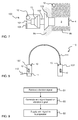
- FIG. 1 schematically indicates three main signal paths P1, P2, P3 from the vocal chords 1 to the basilar membrane in the inner ear of a human individual.
- the signal paths P1, P2, P3 are also indicated in FIG. 2 , which schematically represents the human auditory system, i.e. the human ear.
- sound waves are conducted in free air into the ear. As seen in FIG.
- these airborne sound waves are collected by the auricle (outer ear) 2, enter the ear opening and propagate along the ear canal 3 to the eardrum 4.
- the sound waves are modified by a transfer function A( ⁇ ), which is indicated as a blackbox in FIG. 1 .
- signal path P2 sound waves are conducted by the skull and enter the ear canal 3 through the tissue and bone surrounding the ear canal 3.
- the skull includes the cranium and the mandible (cheekbone or jawbone). The sound waves cause the circumferential wall of the ear canal 3 to vibrate, which produces corresponding pressure variations in the ear canal 3. At least some of the pressure variations reach the eardrum 4.
- the sound waves are modified, in sequence, by a first transfer function B 1 ( ⁇ ), which represents the modifications on the sub-path from the vocal chords 1 to the circumferential wall of the ear canal 3, and a second transfer function B 2 ( ⁇ ), which represents the modifications on the sub-path from the circumferential wall of the ear canal 3 to the eardrum 4.
- a first transfer function B 1 ( ⁇ ) which represents the modifications on the sub-path from the vocal chords 1 to the circumferential wall of the ear canal 3
- B 2 ⁇
- temporal pressure variations p e ( ⁇ ) at the eardrum 4 are formed by a combination of sound waves reaching the eardrum 4 on paths P1 and P2.
- the pressure variations p e ( ⁇ ) cause the eardrum 4 to vibrate, and these vibrations are transferred by the ossicles 5 and via the elliptical window 6 to the cochlea 7, where they cause an excitation of the basilar membrane (not shown).
- the transfer function for this process is represented as D( ⁇ ) in FIG. 1 .
- a further excitation of the basilar membrane may occur via the signal path P3, on which sound waves propagate through the skull directly to the cochlea 7.
- the transfer function of path P3 is represented as C( ⁇ ) in FIG. 1 .
- the own-voice perception is given by the total excitation s b ( ⁇ ) of the basilar membrane, which results in an electrical signal being transmitted from hair cells to the brain via the auditory nerve 8.
- the sound waves from the vocal chords 1 reach the basilar membrane on all three signal paths P1-P3 to form a frequency distribution of the own voice that is familiar to the talker. This frequency distribution changes dramatically when the opening is occluded.
- the signal path P1 effectively disappears (A( ⁇ ) ⁇ 0), causing a loss of treble.
- the transfer function B 2 ( ⁇ ) on signal path P2 increases considerably, in particular for frequencies in the low and mid range, i.e. frequencies below about 2 kHz. In certain applications, the disappearance of the signal path P1 may be desirable, e.g.
- the signal path P1 may be restored by the provision of an electric sidetone path that recreates the airborne sound inside the ear canal 3.
- the electric sidetone path may be provided by arranging an external microphone to register the airborne sound generated by the vocal chords 1 and operating a speaker to recreate the airborne sound inside the ear canal 3.
- Such an electric sidetone path may be able to restore the treble lost by the occlusion, but the low and mid frequency range will still be dominated by sound waves originating from signal path P2.
- occlusion of the ear will cause the spectral balance of the own voice to be unfamiliar and often uncomfortable to the talker.
- FIG. 3 shows an example of a system capable of fully or at least partially restoring the spectral balance of a person's own voice.
- the signal paths and the corresponding transfer functions are illustrated in correspondence with FIG. 1 .
- the system includes an earpiece that is mounted to the ear so as to block or substantially block airborne sound from entering the ear canal 3.
- the earpiece may be an implement inserted into the ear canal 3 of the user or an implement that encompasses the outer ear and is applied externally to the skull of the person. Since the ear is occluded, signal path P1 is absent in FIG. 3 .
- the system includes a speaker 10 configured to generate sound waves in the ear canal 3.
- the speaker 10 is operated by a drive signal from a signal generator 11.
- the signal generator 11 is connected to receive a microphone signal from a microphone 12 which is arranged to register airborne sound outside of the occluded ear, and a vibration signal from a vibration sensor 13 which is arranged in contact with the circumferential wall of the ear canal 3 to detect the mechanical vibrations that are formed by the sound waves on signal path P2 ( FIG. 2 ).
- the signal generator 11 includes a first signal modifier 14 configured to apply a transfer function X( ⁇ ) to the microphone signal and generate a first sub-signal, and a second signal modifier 15 configured to apply a transfer function Y( ⁇ ) to the vibration signal and generate a second sub-signal.
- the sub-signals are combined in a signal combiner 16 to form the drive signal for the speaker 10.
- the combination of the microphone 12, the signal modifier 14 and the speaker 10 defines an electric sidetone path that restores the signal path P1 for airborne sound.
- the signal modifier 14 is suitably configured with a transfer function X( ⁇ ) such that the total transfer function of the electric sidetone path is similar to the transfer function A( ⁇ ) of the signal path P1.
- the combination of the vibration sensor 13, the signal modifier 15 and the speaker 10 defines an electric cancellation path that counteracts the enhanced sound wave caused by the change in B 2 ( ⁇ ) from a non-occluded to an occluded ear.
- the signal modifier 15 is configured to generate the second sub-signal as an "anti-signal" that causes the speaker 10 to generate a sound wave that cancels at least part of the enhanced sound wave originating from signal path P2.
- the signal modifier 15 may be configured to completely cancel the sound wave that originates from the signal path P2.
- FIGS 4A-4C illustrate the principles of the electric cancellation by signal modifier 15.
- FIG. 4A illustrates a sound wave W P2 , in this simplified example a triangle wave, which originates from the signal path P2 and should be reduced or canceled.
- the signal modifier 15 Based on the recorded vibration signal from the vibration sensor 13, the signal modifier 15 generates an anti-signal that causes the speaker 10 to transmit an anti-signal sound wave W AS in the ear canal 3.
- the anti-signal sound wave W AS has the same amplitude as the sound wave W P2 but an inverted phase.
- the sound waves W AS , W P2 cancel each other completely at the eardrum 4 when they are combined in the ear canal 3.
- the signal modifier 15 may be seen to set at least one of the phase and the amplitude of the anti-signal sound wave W AS based on the vibration signal from the vibration sensor 13.
- the signal modifier 15 generates the anti-signal as a modified version of the vibration signal, e.g. by subjecting the vibration signal to polarity inversion and amplitude and phase shaping (as a function of frequency).
- the signal modifier 15 may also be configured to apply one or more spectral filters to the vibration signal.
- the signal modifier 15 may thus comprise one or more of at least one spectral filter (for changing the frequency content), at least one amplifier (for changing the magnitude), at least one delay element (for changing the phase), and at least one inverter (for changing the polarity).
- the processing of the vibration signal by the signal modifier 15 when generating the anti-signal yields the transfer function Y( ⁇ ).
- the signal modifier 15 may be configured with a specific transfer function Y( ⁇ ) with knowledge about the transfer function B 2 ( ⁇ ) when the ear is occluded, so as to achieve a reduction of the occlusion effect based on the vibration signal.
- the transfer function B 2 ( ⁇ ) may e.g. be obtained by measurements on a population of different individuals, or by measurements on the specific individual to wear the occluding earpiece.
- the system may be configured to allow the transfer function Y( ⁇ ) to be tuned by the user (or by service personnel) to achieve a desired spectral balance of the user's own voice when the ear is occluded.
- the tuning may be achieved by the user manipulating one or more small controls on the earpiece (cf. 105 in FIGS 5-7 ), causing one or more settings (control parameters) of the signal generator 11 to change.
- the user may be able to change the one or more control parameters of the signal generator 11 via a graphical user interface on a separate electronic device which is connected to the earpiece by wire or wirelessly, such as a mobile phone, a media player, a computer, etc.
- the user may be allowed to change one or more control parameters of the above-mentioned spectral filter(s), amplifier(s), delay element(s) and inverter(s) of the signal modifier 15.
- system may be configured to adaptively adjust these one or more control parameters, as described further below with reference to FIG. 11 .
- the system further includes a so-called voice activation detector 17, which is configured to process the microphone signal for detection of human speech.
- Voice activation detectors are commercially available and well-known in the art.
- the VAD 17 outputs a VAD signal indicating absence or presence of human speech.
- the VAD signal is received by the signal generator 11, which operates to selectively transmit the anti-signal to the speaker when the VAD signal indicates that the user speaks.
- the VAD signal is supplied to the combiner 16 which thereby selectively combines the anti-signal from the modifier 15 with the sub-signal from the signal modifier 14.
- the VAD signal is instead supplied to the signal modifier 14, which is controlled to only generate the anti-signal when the VAD signal indicates that the user speaks.
- the VAD 17 is optional and may be combined with all embodiments disclosed herein. It should be understood that the VAD 17 need not be connected to the microphone 12 but could be a separate unit with a dedicated sensor for voice detection.
- the signal modifiers 14, 15 need not be connected to a common speaker via a signal combiner 16, but could be connected to a respective speaker.
- the signal combiner 16 is omitted.
- the signal generator 11 may be configured to receive at least one further signal and supply the further signal(s) to the speaker 10, via the signal combiner 16, for generating sound waves in the ear canal 3.
- a further signal may be any type of audio signal that the user may want to listen to, e.g. a music signal, a radio signal, an incoming call signal supplied by a telephone, etc. It is also conceivable that such a system is configured without the electric sidetone path that restores the airborne signal path P1, i.e. the microphone 12 and the signal modifier 14 are omitted.
- FIG. 3 may be seen to disclose a system which is configured, in addition to reducing the occlusion effect, to receive at least one utility signal and operate the speaker 10, or an auxiliary speaker (not shown), to generate corresponding sound waves in the ear canal 3, where the utility signal may be a microphone signal representing airborne sound in the surroundings of the earpiece that occludes the ear, a microphone signal representing airborne sound generated by the user speaking when the earpiece occludes the ear, or a remotely generated and electronically transmitted sound signal (music, telephone call, etc).
- This type of system with playback of a utility signal may e.g.
- hearables as known as smart headphones or smart advisors
- Hearables may be designed for purposes ranging from wireless transmission to communication objectives, medical monitoring and fitness tracking.
- the system in FIG. 3 is modified by removing the microphone 12, the signal modifier 14 and the signal combiner 16, and connecting the signal modifier 15 directly to the speaker 10.
- Such a system without both electric sidetone path and input of a utility signal may be used in passive hearing protection devices that block external sounds.
- the earpieces may be configured as either earplugs for insertion in the ear canal 3 or earmuffs for covering the auricle 2.
- FIG. 5 shows an example of an earpiece 100 that integrates at least part of the system in FIG. 3 .
- FIG. 5 also shows internal components that normally are hidden from view, such as the speaker 10, the microphone 12, and the vibration sensor 13.
- the earpiece 100 in FIG. 5 is configured for insertion in the outer opening of the ear canal 3.
- the earpiece 100 comprises a miniaturized shell, case or housing 101 in the form of an earplug, which may have the shape as shown, or any other suitable shape, with an ear canal tip or dome 102 designed to fit in the ear canal 3 and be supported therein and by the immediately adjacent portion of the auricle 2.
- the housing 101 may be formed of plastic, silicone, metal, or other suitable material.
- the tip 102 may be of either formable or pre-molded material.
- the housing 101 holds the speaker 10, which is arranged to face the insertion end of the earpiece 100 in alignment with a hollow tube portion 103 that extends from the housing 101 to define an open outlet opening. Thereby, sound waves generated by the speaker 10 will propagate through the tube portion 103 and via the outlet opening into the ear canal 3.
- the tip 102 is attached to or integrally formed with the tube portion 103.
- the vibration sensor 13 is arranged beneath the tip 102 at the insertion end.
- the housing 101 further holds the microphone 12, which is arranged at the back end of the housing 101 and is exposed to pick up airborne sound in the surroundings of the earpiece 100.
- the microphone 12 may be spaced from the earpiece 100, e.g. located on a wire connected to the earpiece 100, such as on a headset wire, or located in an electronic device connected to the earpiece 100, such as a mobile phone. As understood from the foregoing, the microphone 12 may also be omitted from the system.
- the earpiece also includes a user interface 105 that allows the user to modify the anti-signal sound waves generated by the system, e.g. by modifying the above-mentioned control parameters of the signal modifier 15.
- the earpiece 100 also contains the signal generator 11 and the VAD 17 (if present).
- Such an earpiece 100 may be a standalone device that also contains a power supply, such as a battery.
- the earpiece 100 is configured to be connected, wirelessly or by wire, to an external device. All or part of the signal generator 11 and the VAD 17 (if present) may be implemented by the external device. The earpiece 100 may be powered by the external device.
- FIG. 6 shows the earpiece 100 of FIG. 5 mounted in an ear canal 3.
- the tip 102 is deformed into engagement with skull tissue 9a, e.g. cartilaginous tissue, and skull bone 9b that define the circumferential wall of the ear canal 3.
- skull tissue 9a e.g. cartilaginous tissue
- skull bone 9b that define the circumferential wall of the ear canal 3.
- the vibration sensor 13 is brought into firm engagement with the circumferential wall of the ear canal 9, via the material of the tip 102.
- the vibration sensor 13 is operable to sense and quantify the temporal movement (vibration) of the circumferential wall.
- FIG. 7 shows an earpiece 100 that lacks integrated vibration sensor 13. Instead a separate vibration sensor 13 is engaged with the skull bone 9b spaced from the ear canal 3.
- the vibration sensor 13 may be connected by wire (not shown) to the earpiece 100. It is important to understand that the system in FIG. 3 does not require the vibrations to be measured at the circumferential wall of the ear canal 3. A sufficiently accurate estimate of the vibrations of the circumferential wall may be obtained by measuring vibrations of the skull bone 9b spaced from the ear canal 3, e.g. at the side of the head above the auricle, as shown in FIG. 7 , or on the cheekbone.
- FIG. 8 shows an over-ear (circumaural) headphone 110 which has two earpieces 100' in the shape of cups, which are configured to be applied over the respective ear of the wearer.
- the respective earpiece 101' encompasses the auricle and occludes the ear canal.
- the earpieces 100' which are configured to reduce the occlusion effect, are mechanically supported by a headband 111 for arrangement on the head of the wearer.
- Each earpiece 100' includes a speaker 10 and a vibration sensor 13.
- the vibration sensor 13 is arranged for engagement with the skull bone of the wearer so as to sense vibrations at a location spaced from the ear canal.
- a signal generator 11 is arranged in one of the earpieces 100' to generate an anti-signal based on the output of the respective vibration sensor 13 and supply the anti-signal signal to the respective speaker 10.
- the signal generator 11 is also configured to receive a utility signal via cable 112 and convey a corresponding signal to the speakers 10.
- the cable 112 also supplies power to the signal generator 11.
- Embodiments of the invention may also be described as a method for restoring, fully or in part, the spectral balance of a person's own voice when an earpiece is mounted to an ear of the person so as to substantially block airborne sound from entering the ear canal.
- FIG. 9 is a flow chart of an exemplary method, which may be executed by the signal generator 11 in FIG. 3 .
- the method involves a step S1 of retrieving the vibration signal from the vibration sensor 13, which is arranged in engagement with the skull to sense vibrations that originate from sound waves that have propagated on the signal path P2, i.e. from the vocal chords through the skull to the vibration sensor 13.
- the method further involves a step S2 of generating the anti-signal based on the vibration signal, and a step S3 of supplying the anti-signal to the speaker 10 so as to generate sound waves in the ear canal 3 that at least partially cancel sound waves in the ear canal 3 that originate from the signal path P2.
- the method may be implemented by the above-mentioned signal generator 11.
- the method may be implemented by software instructions running on a processing device, such as a microprocessor, microcontroller, DSP, etc.
- the software instructions are supplied on a computer-readable medium for execution by the processing device in conjunction with an electronic memory in the signal generator 11.
- the computer-readable medium may be a tangible product (e.g. magnetic medium, optical disk, read-only memory, flash memory, etc) or a propagating signal.
- FIG. 10 shows an example of a system including a noise controller 20 implementing feed-forward control.
- the noise controller 20 is connected to receive a microphone signal from a microphone 12 which is placed at the exterior of the occluding implement to detect incoming ambient noise.
- the noise controller 20 is configured to generate a noise cancelling signal by setting coefficients of a feed-forward filter operating on the microphone signal.
- the noise cancelling signal is supplied to the combiner 16.
- the combiner 16 combines the noise cancelling signal with both the anti-signal from the signal modifier 15 and an audio signal from an audio signal source 21.
- the audio signal may be any type of signal that the user may want to listen to, e.g.
- Noise controllers are well-known in the art and will not be described in further detail. It may be noted that the noise controller 20 operates independently of the signal modifier 15, and that the signal modifier 15 operates to further improve the user's perception of the audio signal in case the user talks while listening to the audio signal.
- FIG. 11 shows a variant of the system in FIG. 3 .
- the signal modifier 15 is connected to receive a microphone signal from an internal microphone 22, which is located to detect sound in the ear canal.
- the microphone 22 may be integrated in the earpiece 100, 100' so as to be exposed to the ear canal 3 when the earpiece 100, 100' is mounted to the ear.
- the signal modifier 15 is configured to adaptively adjust one or more control parameters, e.g. a parameter of any one of the above-mentioned spectral filter(s), amplifier(s), delay element(s) and inverter(s), so as to achieve a desired sound pattern in the ear canal, as detected by the microphone 22.
- control parameters e.g. a parameter of any one of the above-mentioned spectral filter(s), amplifier(s), delay element(s) and inverter(s
- 11 may also include one or more of an electric sidetone path, e.g. as shown in FIG. 3 , an audio signal input path, e.g. as shown in FIG. 10 , and active noise cancellation, e.g. as shown in FIG. 10 .
- embodiments of the invention provide a technique that improves the talking situation of a user with an occluded ear, by reducing the user's perception of bone-conducted sounds in one or more frequency bands.
- the technique allows the eardrum to be isolated from airborne sounds (passive noise cancellation) since the earpiece is arranged to seal off the ear canal.
- the technique may use standard components and is thereby inexpensive and simple to implement.
- the technique may be combined with active noise cancellation and/or an electric sidetone path. Further, the bass performance for audio reproduction in the ear canal is not compromised by the use of the technique.
Priority Applications (3)
| Application Number | Priority Date | Filing Date | Title |
|---|---|---|---|
| EP15200130.1A EP3182721A1 (fr) | 2015-12-15 | 2015-12-15 | Contrôle d'expérience own-voice de locuteur avec oreille occultée |
| US15/356,642 US9949048B2 (en) | 2015-12-15 | 2016-11-20 | Controlling own-voice experience of talker with occluded ear |
| CN201611152785.XA CN106888414A (zh) | 2015-12-15 | 2016-12-14 | 具有闭塞耳朵的说话者的自身语音体验的控制 |
Applications Claiming Priority (1)
| Application Number | Priority Date | Filing Date | Title |
|---|---|---|---|
| EP15200130.1A EP3182721A1 (fr) | 2015-12-15 | 2015-12-15 | Contrôle d'expérience own-voice de locuteur avec oreille occultée |
Publications (1)
| Publication Number | Publication Date |
|---|---|
| EP3182721A1 true EP3182721A1 (fr) | 2017-06-21 |
Family
ID=54849897
Family Applications (1)
| Application Number | Title | Priority Date | Filing Date |
|---|---|---|---|
| EP15200130.1A Withdrawn EP3182721A1 (fr) | 2015-12-15 | 2015-12-15 | Contrôle d'expérience own-voice de locuteur avec oreille occultée |
Country Status (3)
| Country | Link |
|---|---|
| US (1) | US9949048B2 (fr) |
| EP (1) | EP3182721A1 (fr) |
| CN (1) | CN106888414A (fr) |
Cited By (1)
| Publication number | Priority date | Publication date | Assignee | Title |
|---|---|---|---|---|
| EP4266705A1 (fr) * | 2022-04-20 | 2023-10-25 | Absolute Audio Labs B.V. | Procédé de traitement audio d'un dispositif vestimentaire automatique |
Families Citing this family (30)
| Publication number | Priority date | Publication date | Assignee | Title |
|---|---|---|---|---|
| EP4098178B1 (fr) | 2014-08-06 | 2024-04-10 | Yukka Magic LLC | Modules de capteur physiologique optique avec réduction du bruit de signal |
| US10462567B2 (en) | 2016-10-11 | 2019-10-29 | Ford Global Technologies, Llc | Responding to HVAC-induced vehicle microphone buffeting |
| US10678502B2 (en) * | 2016-10-20 | 2020-06-09 | Qualcomm Incorporated | Systems and methods for in-ear control of remote devices |
| US10525921B2 (en) | 2017-08-10 | 2020-01-07 | Ford Global Technologies, Llc | Monitoring windshield vibrations for vehicle collision detection |
| US10562449B2 (en) * | 2017-09-25 | 2020-02-18 | Ford Global Technologies, Llc | Accelerometer-based external sound monitoring during low speed maneuvers |
| US10511915B2 (en) * | 2018-02-08 | 2019-12-17 | Facebook Technologies, Llc | Listening device for mitigating variations between environmental sounds and internal sounds caused by the listening device blocking an ear canal of a user |
| KR101958257B1 (ko) * | 2018-03-12 | 2019-07-02 | 부전전자 주식회사 | 기압평형수단이 구비된 이어폰 |
| CN108519871B (zh) * | 2018-03-30 | 2020-07-21 | Oppo广东移动通信有限公司 | 音频信号处理方法及相关产品 |
| CN108810692A (zh) * | 2018-05-25 | 2018-11-13 | 会听声学科技(北京)有限公司 | 主动降噪系统、主动降噪方法及耳机 |
| DE102018209822A1 (de) * | 2018-06-18 | 2019-12-19 | Sivantos Pte. Ltd. | Verfahren zur Steuerung der Datenübertragung zwischen zumindest einem Hörgerät und einem Peripheriegerät eines Hörgerätesystems sowie Hörgerät |
| US10657950B2 (en) | 2018-07-16 | 2020-05-19 | Apple Inc. | Headphone transparency, occlusion effect mitigation and wind noise detection |
| CN113016193B (zh) * | 2018-11-25 | 2024-02-23 | 株式会社慕悟 | 耳机 |
| CN109660930B (zh) * | 2018-12-14 | 2021-05-14 | 声佗医疗科技(上海)有限公司 | 一种振动部件测试系统和方法 |
| JP7287612B2 (ja) | 2019-01-29 | 2023-06-06 | 国立大学法人山口大学 | 生体情報取得装置 |
| EP3694227A1 (fr) * | 2019-02-07 | 2020-08-12 | Oticon A/s | Dispositif auditif comprenant un évent réglable |
| CN109889966A (zh) * | 2019-03-07 | 2019-06-14 | 钰太芯微电子科技(上海)有限公司 | 基于微机电系统的骨传导传感器 |
| CN112400326B (zh) * | 2019-06-11 | 2023-02-28 | 深圳市汇顶科技股份有限公司 | 一种骨传声信号处理方法、装置、芯片、耳机及存储介质 |
| CN112992114A (zh) * | 2019-12-12 | 2021-06-18 | 深圳市韶音科技有限公司 | 噪声控制系统和方法 |
| CN113132841B (zh) * | 2019-12-31 | 2022-09-09 | 华为技术有限公司 | 降低耳机闭塞效应的方法及相关装置 |
| MX2022013115A (es) * | 2020-04-20 | 2022-11-14 | Polaris Inc | Sistemas y metodos para comunicar informacion. |
| US11521643B2 (en) | 2020-05-08 | 2022-12-06 | Bose Corporation | Wearable audio device with user own-voice recording |
| CN114467311A (zh) * | 2020-07-24 | 2022-05-10 | 华为技术有限公司 | 主动降噪的方法与装置 |
| US11335362B2 (en) | 2020-08-25 | 2022-05-17 | Bose Corporation | Wearable mixed sensor array for self-voice capture |
| CN115398930A (zh) | 2020-08-29 | 2022-11-25 | 深圳市韶音科技有限公司 | 一种获取振动传递函数的方法和系统 |
| US11259119B1 (en) * | 2020-10-06 | 2022-02-22 | Qualcomm Incorporated | Active self-voice naturalization using a bone conduction sensor |
| US11337000B1 (en) * | 2020-10-23 | 2022-05-17 | Knowles Electronics, Llc | Wearable audio device having improved output |
| CN113395629B (zh) * | 2021-07-19 | 2022-07-22 | 歌尔科技有限公司 | 一种耳机及其音频处理方法、装置、存储介质 |
| CN113645534A (zh) * | 2021-08-31 | 2021-11-12 | 歌尔科技有限公司 | 一种耳机闭塞效应消除方法及耳机 |
| CN113873388A (zh) * | 2021-10-27 | 2021-12-31 | 歌尔科技有限公司 | 一种耳机闭塞效应消除方法及耳机 |
| CN114071306B (zh) * | 2021-11-29 | 2023-02-28 | 歌尔科技有限公司 | 降噪耳机音频处理方法、降噪耳机、装置及可读存储介质 |
Citations (4)
| Publication number | Priority date | Publication date | Assignee | Title |
|---|---|---|---|---|
| WO2004021740A1 (fr) * | 2002-09-02 | 2004-03-11 | Oticon A/S | Procede de lutte contre les effets d'occlusion |
| US20090310805A1 (en) * | 2008-06-14 | 2009-12-17 | Michael Petroff | Hearing aid with anti-occlusion effect techniques and ultra-low frequency response |
| WO2014194932A1 (fr) * | 2013-06-03 | 2014-12-11 | Phonak Ag | Procédé de fonctionnement d'un dispositif auditif et dispositif auditif |
| WO2014198307A1 (fr) * | 2013-06-12 | 2014-12-18 | Phonak Ag | Procédé de mise en fonctionnement d'un dispositif auditif capable d'un contrôleur actif d'occlusion et dispositif à contrôle actif d'occlusion |
Family Cites Families (9)
| Publication number | Priority date | Publication date | Assignee | Title |
|---|---|---|---|---|
| US8401212B2 (en) * | 2007-10-12 | 2013-03-19 | Earlens Corporation | Multifunction system and method for integrated hearing and communication with noise cancellation and feedback management |
| EP2296750B1 (fr) * | 2008-06-13 | 2015-12-16 | Cochlear Americas | Capteur de son implantable pour prothèses auditives |
| JP5607824B2 (ja) * | 2010-07-05 | 2014-10-15 | ヴェーデクス・アクティーセルスカプ | 補聴器ユーザの閉塞効果を計測しかつ確認するシステムおよび方法 |
| EP3767926A3 (fr) * | 2010-12-27 | 2021-03-24 | FINEWELL Co., Ltd. | Unité d'appel entrant |
| US9020160B2 (en) * | 2012-11-02 | 2015-04-28 | Bose Corporation | Reducing occlusion effect in ANR headphones |
| EP3008920B1 (fr) * | 2013-06-12 | 2020-08-19 | Sonova AG | Procédé de fonctionnement d'un dispositif auditif capable d'une commande d'occlusion active, et dispositif auditif ayant une commande d'occlusion active ajustable par l'utilisateur |
| EP2849462B1 (fr) * | 2013-09-17 | 2017-04-12 | Oticon A/s | Dispositif d'aide auditive comprenant un système de transducteur d'entrée |
| US9905217B2 (en) * | 2014-10-24 | 2018-02-27 | Elwha Llc | Active cancellation of noise in temporal bone |
| US9706290B2 (en) * | 2015-02-27 | 2017-07-11 | Apple Inc. | Balanced armature based valve |
-
2015
- 2015-12-15 EP EP15200130.1A patent/EP3182721A1/fr not_active Withdrawn
-
2016
- 2016-11-20 US US15/356,642 patent/US9949048B2/en active Active
- 2016-12-14 CN CN201611152785.XA patent/CN106888414A/zh active Pending
Patent Citations (4)
| Publication number | Priority date | Publication date | Assignee | Title |
|---|---|---|---|---|
| WO2004021740A1 (fr) * | 2002-09-02 | 2004-03-11 | Oticon A/S | Procede de lutte contre les effets d'occlusion |
| US20090310805A1 (en) * | 2008-06-14 | 2009-12-17 | Michael Petroff | Hearing aid with anti-occlusion effect techniques and ultra-low frequency response |
| WO2014194932A1 (fr) * | 2013-06-03 | 2014-12-11 | Phonak Ag | Procédé de fonctionnement d'un dispositif auditif et dispositif auditif |
| WO2014198307A1 (fr) * | 2013-06-12 | 2014-12-18 | Phonak Ag | Procédé de mise en fonctionnement d'un dispositif auditif capable d'un contrôleur actif d'occlusion et dispositif à contrôle actif d'occlusion |
Non-Patent Citations (1)
| Title |
|---|
| KIESSLING ET AL.: "Occlusion effect of earmolds with different venting systems", JOURNAL OF THE AMERICAN ACADEMY OF AUDIOLOGY, vol. 16, 2005, pages 237 - 249 |
Cited By (1)
| Publication number | Priority date | Publication date | Assignee | Title |
|---|---|---|---|---|
| EP4266705A1 (fr) * | 2022-04-20 | 2023-10-25 | Absolute Audio Labs B.V. | Procédé de traitement audio d'un dispositif vestimentaire automatique |
Also Published As
| Publication number | Publication date |
|---|---|
| US20170171679A1 (en) | 2017-06-15 |
| US9949048B2 (en) | 2018-04-17 |
| CN106888414A (zh) | 2017-06-23 |
Similar Documents
| Publication | Publication Date | Title |
|---|---|---|
| US9949048B2 (en) | Controlling own-voice experience of talker with occluded ear | |
| US11240588B2 (en) | Sound reproducing apparatus | |
| US10721572B2 (en) | Hearing aid including a vibrator touching a pinna | |
| CA2621916C (fr) | Appareil et procede permettant d'ameliorer un son | |
| US11265660B2 (en) | Speech intelligibility enhancing system | |
| JP2017163531A (ja) | 頭部装着聴覚装置 | |
| CN109565626B (zh) | 具有主动降噪功能的声学开放式耳机 | |
| JP6495448B2 (ja) | ヘッドセット内の自己音声閉塞軽減 | |
| JP2018522504A (ja) | インイヤ型ヘッドホンによる雑音低減 | |
| EP3627848A1 (fr) | Procédé de fonctionnement d'un dispositif auditif et dispositif auditif comprenant une aération active | |
| US11146884B2 (en) | Transducer apparatus for high speech intelligibility in noisy environments | |
| CN113923550A (zh) | 用于主动阻塞消除的耳机、听力设备和系统 | |
| US20200090636A1 (en) | In-ear microphone with active noise control | |
| JP2017125937A (ja) | 音声信号処理装置 | |
| CN116438810A (zh) | 一种听力辅助装置 | |
| KR200426390Y1 (ko) | 마이크를 구비하는 이어폰 | |
| US11862138B2 (en) | Hearing device comprising an active emission canceller | |
| EP4297436A1 (fr) | Prothèse auditive comprenant un système d'annulation d'occlusion actif et procédé correspondant | |
| TW201508376A (zh) | 用於眼鏡之聲音感應耳部揚聲器 | |
| CN117581562A (zh) | 主动降噪耳塞 | |
| AU2005282209A1 (en) | Apparatus and method for sound enhancement |
Legal Events
| Date | Code | Title | Description |
|---|---|---|---|
| PUAI | Public reference made under article 153(3) epc to a published international application that has entered the european phase |
Free format text: ORIGINAL CODE: 0009012 |
|
| AK | Designated contracting states |
Kind code of ref document: A1 Designated state(s): AL AT BE BG CH CY CZ DE DK EE ES FI FR GB GR HR HU IE IS IT LI LT LU LV MC MK MT NL NO PL PT RO RS SE SI SK SM TR |
|
| AX | Request for extension of the european patent |
Extension state: BA ME |
|
| 17P | Request for examination filed |
Effective date: 20171218 |
|
| RBV | Designated contracting states (corrected) |
Designated state(s): AL AT BE BG CH CY CZ DE DK EE ES FI FR GB GR HR HU IE IS IT LI LT LU LV MC MK MT NL NO PL PT RO RS SE SI SK SM TR |
|
| 17Q | First examination report despatched |
Effective date: 20180316 |
|
| STAA | Information on the status of an ep patent application or granted ep patent |
Free format text: STATUS: THE APPLICATION IS DEEMED TO BE WITHDRAWN |
|
| 18D | Application deemed to be withdrawn |
Effective date: 20180927 |