EP3182697A1 - Verfahren und vorrichtung zur korrektur des vignettierungseffekts auf einem mit einer lichtfeldkamera aufgenommenen bild - Google Patents
Verfahren und vorrichtung zur korrektur des vignettierungseffekts auf einem mit einer lichtfeldkamera aufgenommenen bild Download PDFInfo
- Publication number
- EP3182697A1 EP3182697A1 EP15307003.2A EP15307003A EP3182697A1 EP 3182697 A1 EP3182697 A1 EP 3182697A1 EP 15307003 A EP15307003 A EP 15307003A EP 3182697 A1 EP3182697 A1 EP 3182697A1
- Authority
- EP
- European Patent Office
- Prior art keywords
- photosite
- values
- lightfield camera
- photosites
- luminance
- Prior art date
- Legal status (The legal status is an assumption and is not a legal conclusion. Google has not performed a legal analysis and makes no representation as to the accuracy of the status listed.)
- Withdrawn
Links
- 238000000034 method Methods 0.000 title claims abstract description 53
- 230000000694 effects Effects 0.000 title claims abstract description 48
- 230000035945 sensitivity Effects 0.000 claims description 34
- 238000012937 correction Methods 0.000 claims description 8
- 239000003086 colorant Substances 0.000 claims description 3
- 238000004891 communication Methods 0.000 claims description 2
- 238000004590 computer program Methods 0.000 claims 2
- 230000015654 memory Effects 0.000 description 27
- 239000011159 matrix material Substances 0.000 description 24
- 230000008569 process Effects 0.000 description 19
- 238000004364 calculation method Methods 0.000 description 18
- 230000002093 peripheral effect Effects 0.000 description 15
- 238000004519 manufacturing process Methods 0.000 description 11
- 241000282326 Felis catus Species 0.000 description 9
- 230000003287 optical effect Effects 0.000 description 6
- 230000008859 change Effects 0.000 description 5
- 238000012545 processing Methods 0.000 description 5
- 238000010586 diagram Methods 0.000 description 4
- 238000012986 modification Methods 0.000 description 3
- 230000004048 modification Effects 0.000 description 3
- 238000007792 addition Methods 0.000 description 2
- 230000005540 biological transmission Effects 0.000 description 2
- 238000006243 chemical reaction Methods 0.000 description 2
- 238000013461 design Methods 0.000 description 2
- 230000006870 function Effects 0.000 description 2
- 238000009434 installation Methods 0.000 description 2
- 239000000203 mixture Substances 0.000 description 2
- 210000001747 pupil Anatomy 0.000 description 2
- 230000003466 anti-cipated effect Effects 0.000 description 1
- 238000013459 approach Methods 0.000 description 1
- 230000002301 combined effect Effects 0.000 description 1
- 230000003247 decreasing effect Effects 0.000 description 1
- 230000008020 evaporation Effects 0.000 description 1
- 238000001704 evaporation Methods 0.000 description 1
- 238000009472 formulation Methods 0.000 description 1
- 238000003384 imaging method Methods 0.000 description 1
- CFZXDJWFRVEWSR-BUHFOSPRSA-N indigo carmine (acid form) Chemical compound N/1C2=CC=C(S(O)(=O)=O)C=C2C(=O)C\1=C1/NC2=CC=C(S(=O)(=O)O)C=C2C1=O CFZXDJWFRVEWSR-BUHFOSPRSA-N 0.000 description 1
- 230000010354 integration Effects 0.000 description 1
- 229920001690 polydopamine Polymers 0.000 description 1
- 230000004044 response Effects 0.000 description 1
- 230000008054 signal transmission Effects 0.000 description 1
- 238000001228 spectrum Methods 0.000 description 1
- 230000032258 transport Effects 0.000 description 1
Images


Classifications
-
- G06T5/80—
-
- G—PHYSICS
- G02—OPTICS
- G02B—OPTICAL ELEMENTS, SYSTEMS OR APPARATUS
- G02B3/00—Simple or compound lenses
- G02B3/0006—Arrays
-
- G—PHYSICS
- G02—OPTICS
- G02B—OPTICAL ELEMENTS, SYSTEMS OR APPARATUS
- G02B7/00—Mountings, adjusting means, or light-tight connections, for optical elements
- G02B7/02—Mountings, adjusting means, or light-tight connections, for optical elements for lenses
- G02B7/021—Mountings, adjusting means, or light-tight connections, for optical elements for lenses for more than one lens
-
- H—ELECTRICITY
- H04—ELECTRIC COMMUNICATION TECHNIQUE
- H04N—PICTORIAL COMMUNICATION, e.g. TELEVISION
- H04N23/00—Cameras or camera modules comprising electronic image sensors; Control thereof
- H04N23/10—Cameras or camera modules comprising electronic image sensors; Control thereof for generating image signals from different wavelengths
- H04N23/12—Cameras or camera modules comprising electronic image sensors; Control thereof for generating image signals from different wavelengths with one sensor only
-
- H—ELECTRICITY
- H04—ELECTRIC COMMUNICATION TECHNIQUE
- H04N—PICTORIAL COMMUNICATION, e.g. TELEVISION
- H04N23/00—Cameras or camera modules comprising electronic image sensors; Control thereof
- H04N23/50—Constructional details
- H04N23/55—Optical parts specially adapted for electronic image sensors; Mounting thereof
-
- H—ELECTRICITY
- H04—ELECTRIC COMMUNICATION TECHNIQUE
- H04N—PICTORIAL COMMUNICATION, e.g. TELEVISION
- H04N23/00—Cameras or camera modules comprising electronic image sensors; Control thereof
- H04N23/70—Circuitry for compensating brightness variation in the scene
- H04N23/75—Circuitry for compensating brightness variation in the scene by influencing optical camera components
-
- H—ELECTRICITY
- H04—ELECTRIC COMMUNICATION TECHNIQUE
- H04N—PICTORIAL COMMUNICATION, e.g. TELEVISION
- H04N23/00—Cameras or camera modules comprising electronic image sensors; Control thereof
- H04N23/95—Computational photography systems, e.g. light-field imaging systems
- H04N23/957—Light-field or plenoptic cameras or camera modules
-
- H—ELECTRICITY
- H04—ELECTRIC COMMUNICATION TECHNIQUE
- H04N—PICTORIAL COMMUNICATION, e.g. TELEVISION
- H04N25/00—Circuitry of solid-state image sensors [SSIS]; Control thereof
- H04N25/40—Extracting pixel data from image sensors by controlling scanning circuits, e.g. by modifying the number of pixels sampled or to be sampled
- H04N25/41—Extracting pixel data from a plurality of image sensors simultaneously picking up an image, e.g. for increasing the field of view by combining the outputs of a plurality of sensors
-
- H—ELECTRICITY
- H04—ELECTRIC COMMUNICATION TECHNIQUE
- H04N—PICTORIAL COMMUNICATION, e.g. TELEVISION
- H04N25/00—Circuitry of solid-state image sensors [SSIS]; Control thereof
- H04N25/50—Control of the SSIS exposure
-
- H—ELECTRICITY
- H04—ELECTRIC COMMUNICATION TECHNIQUE
- H04N—PICTORIAL COMMUNICATION, e.g. TELEVISION
- H04N25/00—Circuitry of solid-state image sensors [SSIS]; Control thereof
- H04N25/60—Noise processing, e.g. detecting, correcting, reducing or removing noise
- H04N25/61—Noise processing, e.g. detecting, correcting, reducing or removing noise the noise originating only from the lens unit, e.g. flare, shading, vignetting or "cos4"
-
- H—ELECTRICITY
- H04—ELECTRIC COMMUNICATION TECHNIQUE
- H04N—PICTORIAL COMMUNICATION, e.g. TELEVISION
- H04N9/00—Details of colour television systems
- H04N9/64—Circuits for processing colour signals
- H04N9/646—Circuits for processing colour signals for image enhancement, e.g. vertical detail restoration, cross-colour elimination, contour correction, chrominance trapping filters
-
- G—PHYSICS
- G06—COMPUTING; CALCULATING OR COUNTING
- G06T—IMAGE DATA PROCESSING OR GENERATION, IN GENERAL
- G06T2207/00—Indexing scheme for image analysis or image enhancement
- G06T2207/10—Image acquisition modality
- G06T2207/10052—Images from lightfield camera
-
- G—PHYSICS
- G06—COMPUTING; CALCULATING OR COUNTING
- G06T—IMAGE DATA PROCESSING OR GENERATION, IN GENERAL
- G06T7/00—Image analysis
- G06T7/50—Depth or shape recovery
- G06T7/55—Depth or shape recovery from multiple images
- G06T7/557—Depth or shape recovery from multiple images from light fields, e.g. from plenoptic cameras
-
- H—ELECTRICITY
- H04—ELECTRIC COMMUNICATION TECHNIQUE
- H04N—PICTORIAL COMMUNICATION, e.g. TELEVISION
- H04N2209/00—Details of colour television systems
- H04N2209/04—Picture signal generators
- H04N2209/041—Picture signal generators using solid-state devices
- H04N2209/042—Picture signal generators using solid-state devices having a single pick-up sensor
- H04N2209/045—Picture signal generators using solid-state devices having a single pick-up sensor using mosaic colour filter
Definitions
- the present disclosure generally relates to the field of multiple views imaging, notably multiple lightfields using lightfield cameras.
- Lightfield cameras are able to measure the amount of light traveling along each ray bundle that intersects the image sensor by using a micro lens array that is placed between the main lens and the image sensor. This light field is then post-processed to reconstruct images of the scene from different points of view. The light field also permits a user to change the focal point of the images.
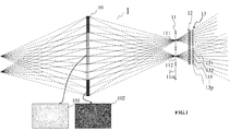
- Fig. 1 shows illustrative configuration of a lightfield camera.
- the lightfield camera 1 comprises a lens arrangement associated with an image sensor array 13.
- the image sensor array 13 comprises a large number p of photosites 131, 132, 133 to 13p arranged in the form of a grid of X columns and Y lines, n being a number of elements corresponding to X times Y.
- a color filter array 12 is arranged on the image sensor array 13.
- the color filter array 12 typically arranges RGB (Red, Green and Blue) color filters on the image sensor array 13, the RGB arrangement can be, for example, the form of a Bayer filter mosaic.
- the lens arrangement comprises a primary lens 10, also called main lens, and a lenslet array 11 which comprises a plurality of m microlenses 111, 112, 11m, m being a positive integer.
- the microlenses 111, 112, 11m are arranged in such a way as to each be optically associated with a plurality of photosites 131, 132, 133 to 13p .
- the number of photosites 131, 132, 133 to 13p are optically associated with one microlens that corresponds to the number of views of the scene acquired with the lightfield camera.
- the raw image i.e. the color sensor data acquired with the image sensor array 13
- RGB image data values are obtained at each photosite location for each view.
- the captured images of the scene with a lightfield camera should undergo view demultiplexing, i.e., the data conversion from the 2D raw image to the 4D light-field.
- the demultiplexing process consists of reorganizing the photosites of the raw image in such a way that all photosites 131 capturing the light rays with a certain angle of incidence are stored in the same image creating sub-aperture views.
- Each sub-aperture view is a projection of the scene under a different angle.
- the set of sub-aperture views create a block matrix where the central sub-aperture view stores the photosites capturing the light rays that pass through the central section of the main lens.
- the angular information of the light rays is provided by the relative photosites positions in the microlens images in respect to the microlens image centers.
- Fig. 1 illustrates such a drawback of a lightfield camera due to less refracted light energy in peripheral sub-aperture views.
- the dashed line represents light rays which have less refracted light energy due to vignetting effect.
- peripheral sub-aperture views are unusable since they are too dark compared to central sub-aperture views.
- peripheral sub-aperture view 102 (with the collection of peripheral positioning photosites 131 and 133 with respect to the center of microlens images) is not usable since it is too dark, mostly because view 102 is under exposed and therefore noisy.
- central sub-aperture view 101 with the collection of central positioning photosites 132 that captured the light ray passing through the main lens center to the photosite 132 is usable since view 101 is better-exposed and less noisy.
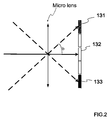
- Fig. 2 shows an enlargement view of image sensor array 13 depicted in Fig. 1 .
- Central photosites 132 capture the light ray that has passed through the center of the main lens to central photosites 132 while peripheral photosites 131 and 133 capture light rays incoming with oblique angle compared with the central photosites 132, the luminance level of peripheral photosite 131 and 133 is less due to several reasons. Firstly, the light ray incoming with oblique angle has a longer way to travel to the image corner. Secondly, the pupil seen by the off-axis point is not round but elliptical and has a smaller area than the round pupil seen by the central photosites 132. Thirdly, while the light hits the image center at normal incidence, the light strikes the image corner at the angle b. The combined effect of all cosine factors is a cos 4 law (cosine forth law) luminance falloff towards the image corners.
- Fig. 3 shows an image of white signal in the central part of a sensor from image array 13.
- the vignetting effect nearly follows a symmetric cos 4 law (cosine forth law) fall-off.
- the vignetting effect can be formulated by a cos 4 law (cosine forth law) factor or a Gaussian fall-off function, for example.
- the difference of the luminance level may be reduced using a weighting matrix derived by dividing the raw data by a corresponding white image (i.e., the image of a Lambertian light-emitting type object).
- reference document EP15306059.5 discloses a way to solve vignetting problem by introducing a gradient filter between the primary lens and the photosites set at the location of the stop aperture.
- the drawback of this approach is that it still needs Lambertian light-emitting type object image to be captured whenever changing the focus/zoom of the camera in order to estimate the position of the microlens images on the photosites.
- the present disclosure proposes a novel method and apparatus to overcome vignetting effect caused an image captured by lightfield cameras, also called plenoptic cameras.
- a method for correcting vignetting effect caused on an image captured by a lightfield camera comprising an image sensor array including plurality of photosites includes: obtaining luminance values from the each photosite; obtaining a set of weight values for compensating the vignetting effect for the each photosite, wherein said a set of weight value is associated with a present setting of the lightfield camera; and changing the luminance values of the each photosite based on the obtained set of the weight values.
- the present principles also relate to a method for correcting vignetting effect caused on an image captured by a lightfield camera comprising image sensor array including plurality of photosites, a primary lens, microlenses located between the image sensor array and the primary lens, and an additional lens being arranged between the primary lens and the microlenses at a distance from the primary lens, the additional lens having a focal length corresponding to the distance.
- the method includes: obtaining luminance values of each photosite; obtaining a set of weight values for compensating the vignetting effect for the each photosite; and changing the luminance values of the each photosite based on the obtained set of weight values.
- the present principles also relate to a device for correcting vignetting effect caused on an image captured by a lightfield camera comprising image sensor array including plurality of photosites, a primary lens, and microlenses located between the image sensor array the primary lens, wherein the device comprises a storage element storing sets of weight values for compensating the vignetting effect for the each photosite being associated with respective settings of the lightfield camera and a processor can communicate with the image sensor array and the storage.
- the processor is configured to perform: obtaining luminance values of each photosite; obtaining a set of weight values for each photosite being associated with a present setting of the lightfield camera; and changing the luminance values of each photosite based on the obtained set of the weight values.
- the present principles also relate to a device for correcting vignetting effect caused on an image captured by a lightfield camera comprising image sensor array including plurality of photosites, a storage storing a set of weight values for compensating the vignetting effect for each photosite and a processor.
- the processor is configured to perform: obtaining luminance values of each photosite captured with a lightfield camera; obtaining a set of weight values for the each photosite; and changing a the luminance values of the each photosite based on the obtained a set of weight values.
- the present principles also relate to a lightfield camera comprising: a primary lens; microlenses; an image sensor array including a plurality of photosites; wherein the photosites have respective sensitivities adjusted for compensating a vignetting effect to be caused on an image to be captured by the lightfield camera.
- the present principles also relate to a method for manufacturing an image sensor array including a plurality of photosites for a lightfield camera using the other lightfield camera comprising the same configuration as the lightfield camera except for photosites of the other lightfield camera having homogeneous sensitivities.
- the method comprising: capturing a Lambertian object image with the other lightfield camera; calculating a set of weight values for compensating a vignetting effect caused on the Lambertian object image for the each photosite of the other lightfield camera based on the captured Lambertian object image; manufacturing the image sensor array including the photosites having respective sensitivities adjusted in accordance with the calculated the set of weight values; wherein the respective weight values are associated with both of the respective photosites of the lightfield camera and respective photosites of the other lightfield camera.
- the present principles also disclose a method for manufacturing an image sensor array including a plurality of photosites for a lightfield camera comprising a primary lens, a lenslet array including a plurality of microlenses, and an additional lens being arranged between the primary lens and the microlenses at a distance from the primary lens, the additional lens having a focal length corresponding to the distance, the image sensor array including a plurality of photosites, using the other lightfield camera comprising the same configuration as the lightfield camera except for photosites of the other lightfield camera having a homogeneous sensitivities.
- the method comprising: capturing a Lambertian object image with the other lightfield camera; calculating a set of weight values for compensating a vignetting effect caused on the Lambertian object image for the each photosite of the other lightfield camera based on the captured Lambertian object image; manufacturing the image sensor array including the photosites having respective sensitivities adjusted in accordance with the calculated the set of weight values; wherein the respective weight values are associated with both of the respective photosites of the lightfield camera and respective photosites of the other lightfield camera.
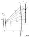
- Fig. 4 shows an illustrative configuration of lightfield camera with an additional lens according to an embodiment of present disclosure.
- One of the technical reference documents, EP15305988.6 discloses the concept of placing an additional lens 21 between the primary lens 10 and the lenslet array 11 so that the position of the microlens images does not depend on zoom/focus of the camera.
- Additional lens 21 is arranged between the primary lens 10 and the lenslet array 11, at a fixed position, e.g. during the manufacturing of the lightfield camera 1 or after the lightfield camera 1 is manufactured, additional lens 21 is displaced or added, at a distance L1 from the primary lens 10 and at a distance L2 from the lenslet array 11.
- the focal length of the additional lens 21 is equal to a value corresponding to the distance L1 between the primary lens 10 and the additional lens 21.
- Additional lens 21 contributes to estimate one set of micro-image centers for every set of focusing-distance/zoom parameters of the lightfield camera 1. In other words, with this solution, the centers of micro-images can be estimated even with different zooming or focalization settings.
- the focal length of the additional lens 21 is equal to the distance L1
- the chief rays of light 301, 302 and 30i passing through the centers of the microlenses 110, 11i are parallel to the optical axis 2001 of the lightfield camera 1, i.e. the rays of light that get out the additional lens and pass through the centers of the microlenses of the lenslet array 11 are parallel to the optical axis 2001 of the lightfield camera 1.
- Setting the focal length of the additional lens 21 to the distance L1 enables a constant distance between the centers of the micro-images formed under the lenslet array 11 on the image sensor array 13.
- the distance between the centers of two adjacent micro-images is equal to the distance, referenced L, between the centers of the corresponding lenslet array 11.
- a regular arrangement of the centers of the micro-images on the image sensor array 13 helps when determining such centers when calibrating the lightfield camera 1. Moreover, as the focal length of the additional lens 21 is controlled to be equal to L1 even when the distance L1 varies (for example when zooming or focusing), the locations of the centers of the micro-images on the image sensor array 13 do not vary. Using such techniques helps avoid the determining of the centers of the micro-images each and every time the zooming and/or focusing parameters of the primary lens 10 change.
- the ray of light 30i is parallel to the optical axis 2001 when outputted from the additional lens 21 and the point hit by this ray 30i is the center 34i of the micro-image formed under the microlens 30i, the same point being hit by the ray 30i, whatever the focusing distance and/or zooming parameter of the primary lens 10, i.e. whatever the value of the distance L1.
- the centers of micro-image can be captured in the same location on the sensor array 13 regardless of the zooming or focalization setting so that changing the sensitivity of photosites will be more effective to solve the technical problem stated in the Background section.
- a calculation for the required photosites sensitivity is performed with having additional lens 21 as shown in Fig. 4 ..
- the installation of additional lens 21 may not be required for a calculation of required photosite sensitivity as long as a lightfield camera 1 is a single-focus camera (in other words, if a lightfield camera 1 does not have a functionality of zoom/focus settings, additional lens 21 may not be required.) or when there is a mean associating a set of weight values to a respective zoom/focus settings.
- calibration steps are performed by capturing uniformly illuminated white object which radiates light equally in all direction (Herein after, it is referred as "Lambertian object"). It is anticipated that such Lambertian object image to be captured should be uniformly white, however an image to be captured is actually not uniformly white due to the vignetting and color filter effect.
- the RGB (Red, Green and Blue) color filters that are arranged on the image sensor array 13 give an effect on luminance level where the effect of color filter should be compensated.
- Fig. 5 shows the vignetting and color filter effects caused on the periphery of the sensor array.
- a min_threshold is preset in order to distinguish between photosites that will be compensated for vignetting fall off effects and photosites that will not be compensated. Some photosites will be in the "shadow" (in other words, such photosites will not receive light) due to the front lens aperture, rear lens aperture and diaphragm aperture.
- a min_threshold can be chosen to decide whether the photosites ever receive light due to the mechanical cat's eye vignetting.
- An example of a min_threshold is 0.1 out of 1. In the present disclosure, those photosites of luminance values that are less than min_threshold will not be compensated, since those photosites are determined as not receiving usable lights due to mechanical cat's eye vignetting.
- the luminance values of each photosite can be multiplied (or reduced) or the sensitivities of the each photosite can also be designed to correct the effect of color filters that are used to sample the color content.
- a photosite behind a blue color filter can be designed more sensitive to capture the same value as the photosite placed behind a green color filter in response to an ideal white signal. The detailed steps are explained later in this part of this description.
- Fig. 6 is a diagram illustrating hardware configuration of a device which discloses various embodiment of present disclosure.
- a device 5 includes lightfield camera 1 (or 1A that will be explained in later section of this description)
- a lightfield camera 1 can be configured separately from a device 5.
- a device 5 can be any device such as, for example, desktop or personal computers, smartphones, smartwatches, tablets, mobile phones, portable/personal digital assistants ("PDAs"), and other devices that facilitate communication of information between end-users and a lightfield camera 1.
- Lightfield camera 1 can also have equivalent hardware configuration of a device 5 inside.
- the device 5 comprises the following elements, which are connected to each other by a bus 54 of addresses and data that also transports a clock signal: a processor 51 (or CPU), a non-volatile memory of ROM (Read Only Memory) type 52, a Random Access Memory or RAM 53, a radio interface (RX) 56, an interface 55 (TX) adapted for the transmission of data, a lightfield camera 1, an MMI (Man Machine Interface) 58 (I/F appli) adapted for displaying information for a user and/or inputting data or parameters.
- a processor 51 or CPU
- ROM Read Only Memory
- RAM 53 Random Access Memory
- RX radio interface
- TX interface 55
- TX adapted for the transmission of data
- a lightfield camera 1 a lightfield camera
- MMI Man Machine Interface
- I/F appli adapted for displaying information for a user and/or inputting data or parameters.
- register or "store” used in the description of memories 52 and 53 designates in each of the memories mentioned, a memory zone of a low capacity as well as a memory zone of a large capacity (enabling a whole program to be stored in such memories or all or part of the data representing data received and decoded for such memories).
- the ROM 52 comprises a program "prog".
- the algorithms implementing the steps of the method specific to the present disclosure and described below are stored in the ROM 52 memory and are associated with the device 5 implementing these steps.
- the processor 51 loads and runs the instructions of these algorithms.
- the RAM 53 notably comprises in a register and/or memory, the operating program of the processor 51 responsible for switching on the device 5, reception parameters (for example parameters for modulation, encoding, MIMO (Multiple Input Multiple Output), recurrence of frames), transmission parameters (for example parameters for modulation, encoding, MIMO, recurrence of frames),incoming data corresponding to the data received and decoded by the radio interface 56, decoded data formed to be transmitted at the interface to the application 58, parameters of the primary lens 10 and/or information representative of the centers of the micro-images formed by the microlenses of the microlens array.
- reception parameters for example parameters for modulation, encoding, MIMO (Multiple Input Multiple Output), recurrence of frames
- transmission parameters for example parameters for modulation, encoding, MIMO, recurrence of frames
- the device 5 may be implemented according to a purely hardware realization, for example in the form of a dedicated component (for example in an ASIC (Application Specific Integrated Circuit) or FPGA (Field-Programmable Gate Array) or VLSI (Very Large Scale Integration) or of several electronic components embedded in an apparatus or even in a form of a mix of hardware elements and software elements.
- ASIC Application Specific Integrated Circuit
- FPGA Field-Programmable Gate Array
- VLSI Very Large Scale Integration
- the radio interface 56 and the interface 55 are adapted for the reception and transmission of signals according to one or several telecommunication standards such as IEEE 802.11 (Wi-Fi), standards compliant with the IMT-2000 specifications (also called 3G), with 3GPP LTE (also called 4G), IEEE 802.15.1 (also called Bluetooth).
- Wi-Fi IEEE 802.11
- 3G 3G
- 4G 3GPP LTE
- IEEE 802.15.1 also called Bluetooth
- the device 5 does not include any ROM but only RAM where the algorithms implementing the steps of the method specific to the present disclosure are stored in the RAM.
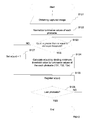
- Fig. 7 shows an illustrative flow chart for calculating a set of weight values for each photosite using a lightfield camera according to an embodiment of present disclosure.
- a calculated weight value w(u,v) may be used to multiply the luminance value of the photosite at location (u,v).
- the steps described in this flowchart can be performed by a processor 51.
- (u,v) refers to a coordinate of i-th photosite on a sensor array 13 plane.
- Each value for "u” and "v” will be incremented in accordance with the number i of the photosite to be processed is incremented at the step 7 (S7).
- processor 51 receives luminance values of all photosite 131, 132, 133 to 13p when a lightfield camera 1 captures image of Lambertian object that uniformly radiates lights equally in all direction.
- the luminance values may be computed with a weighted sum of color components.
- Luminance 1(u,v) ((q_red x 299) + (q_green x 587) + (q_blue x 114)) / 1000;
- Other techniques for calculating luminance values of photosites 131, 132, 133 to 13p can be employed in accordance with the principles of the present disclosure.
- processor 51 also normalizes luminance value of each photosite 131, 132, 133 to 13p so that the maximum value to be transformed to the maximum magnitude that photosites can provide.
- l u v 255 * l u v / max_l
- l'(u,v) represents a normalized luminance value of photosite location at (u,v)
- l(u,v) represents luminance value of photosite location at (u,v)
- max_1 represents maximum luminance value among all the photosite 131, 132, 133 to 13p.
- a processor 51 determines and registers a normalized maximum luminance value.
- a processor 51 may temporary register luminance values of all photosets to a memory such as RAM 53 or ROM 52 and may determine a maximum luminance value from registered all luminance values.
- a processor 51 registers a normalized maximum luminance value to a memory as well.
- a photosite 131, 132, 133 to 13p with the maximum luminance value is usually located close to the central part of sensor array 13.
- a min_threshold is prepared and determined.
- the system in present disclosure regards the photostites 131, 132, 133 to 13p of those luminance values as being less than a threshold are affected due to mechanical cat's eye vignetting and set weight values for those photostites 131, 132, 133 to 13p are equal to 0.
- step 3 processor 51 determines whether the luminance value 1'(u,v) of an i-th photosite 131, 132, 133 to 13p is less than a min_threshold. If it is determined that luminance value of i-th photosite l'(u,v) is less than the min_threshold value, a process proceeds to step 4 (S4). If it is determined that the value l'(u,v) is greater than or equal to the min_threshold, a process proceeds to step 5 (S5).
- step 4 (S4) if it is determined that the luminance value of this i-th photosite 131, 132, 133 to 13p is less than a threshold value, processor 51 sets a weight value for this photosite equal to 0.
- step 5 (S5) processor 51 calculates weight value for this i-th photosite 131, 132, 133 to 13p.
- w(u,v) is used for correcting red, green and blue components.
- processor 51 stores the calculated weight value for this i-th photosite to the memory (weight matrix storage 87).
- the position of the microlens images on the sensor array 13 depends on the camera parameters, e.g., zoom and focus of the camera.
- a set of calculated weight values should be registered to the memory associated with a present zoom/focus setting that is detected by the means not described in the attached figures.
- a weight value may be further associated with a location of the photosite (u,v) on a sensor array 13 plane in order to be applied to a luminance value of corresponding photosite (u,v) on a sensor array 13 plane.
- the weight value calculated for a location of photosite (u,v) on a sensor array 13 plane will be used to multiply the luminance value captured on the same location of photosite (u,v) on a sensor array 13 plane at the later explained step 114 (S 114).
- step 7 processor 51 determines whether this is the last photosite in an array.
- photosite to be processed is expressed in the form of i-th.
- a person skilled in the art may understand that the different form of calculation can be used.
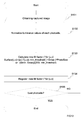
- Fig. 8 shows an illustrative flow chart for alternative embodiment which calculates a set of weight values for each photosite based on the color channel.
- a weight value should be varied since the effects brought by each color channel may differ.
- the entire method described in this flowchart is performed by processor 51.
- (u,v) refers to a coordinate of i-th photosite on a plane of sensor array 13.
- Each value for "u” and “v” will be incremented in accordance with the number i of the photosite to be processed is incremented at the step 80 (S80). Needless to say, there is a mean to detect the color of color filters which corresponds to each photosite.
- Step 10 processor 51 receives luminance values of photosites 131, 132, 133 to 13p when a lightfield camera 1 captures image of Lambertian object that uniformly radiates lights equally in all direction.
- step 1 (S1) in Figure 7 normalizing captured luminance value step is performed.
- l'(u,v), max_1' and q'(max,color) each represents normalized luminance values.
- processor 51 determines a maximum luminance value q'_(max,color) for each color which is comprised in color filter such as Bayer filter from the received signal (all luminance values).
- processor 51 may temporary register luminance values of all the photosites 131, 132, 133 to 13p by associating respective colors of color filters placed onto the respective photosites 131, 132, 133 to 13p.
- processor 51 may register a luminance value associating a color "red" for a photosite 131, 132, 133 to 13p on which red color filter is placed. Then processor 51 may locate the maximum luminance value per each color from registered all luminance values.
- Processor 51 may register respective maximum luminance value to a memory.
- a photosite 131, 132, 133 to 13p with the maximum luminance value is usually located close to the central part of image sensor array 13.
- step 30 processor 51 determines whether the luminance value of i-th photosite l'(u,v) is less than a min_threshold. If it is determined that a luminance value of l'(u,v) is less than the min_threshold value, the process proceeds to step 40 (S40). If it is determined that the value of l'(u,v) is greater than or equal to the min_threshold, the process proceeds to step 50 (S50).
- step 40 (S40) as it is determined that the luminance value of this i-th photosite is less than a threshold value, processor 51 determines that this i-th photosite won't receive light due to mechanical cat's eye vignetting. Processor 51 sets a weight value for this i-th photosite equal to 0.
- step 50 (S50) processor 51 determines the color of color filter on this i-th photosite and obtains a correction value for the color of the color filter on this photosite.
- q'_(max,color) is the normalized maximum luminance value per color measured on the image sensor array 13 when a Lambertian object is captured by a lightfield camera 1.
- h_color is the predetermined correction value corresponding to the color (for example, red, green or blue) of color filter which is placed on the photosite.
- step 70 processor 51 registers the calculated weight value for this i-th photosite.
- processor 51 registers the calculated weight value for this i-th photosite.
- a calculated a set of weight values may be registered to a memory in association with present zoom/focus setting.
- step 80 processor 51 determines whether this is the last photosite by comparing processing photosite number i with the maximum photosite number i max which may be preregistered to the memory. If a photosite is determined to be the last photosite, process is terminated. If it is determined that a photosite is not a last photosite to be calculated for a weight value, processor 51 increments the photosite number i and returns to step 30 (S30) to calculate the weight value for next photosite (i+1-th photosite).
- photosite to be processed is expressed in the form of i-th.
- a person skilled in the art may understand that the different form of calculation can be used.
- Fig. 9 shows an illustrative diagram of a configuration for applying calculated respective weight values to output signals from each photosite according to an embodiment of present disclosure.
- a calculated a set of weight values are applied to the luminance values of each photosite respectively in order to compensate the vignetting effect caused when an image is captured.
- the signal captured by the image sensor array 13 is sent to the analog to digital conversion device 84 via row access drivers 81, column amplifiers 82 and analog gain 83.
- Clocks generation 80 regulates the rate at which instructions are executed.
- the sets of weight values are computed by processor 51 and registered into a weight matrix storage 87.
- signals from each photosite may be multiplied by the corresponding weight values at multiplier 86 in order to compensate the vignetting effects.
- signals from each photosite may be multiplied before being converted to a digital stream. In this implementation, there is no need to adjust the sensitivities of each photosite by changing a sizes or fill factors of each photosite.
- the vignetting effect is compensated after capturing an image in accordance with computed a set of weight values (weight matrix).
- a means for detecting a present setting (such as zoom/focus) of a lightfield camera 1 is not indicated in the attached figure, a lightfield camera 1 can be configured to have such a means.
- the sets of weight values stored at weight matrix storage 87 can be updated by a user.
- the user may download the sets of weight values (sets of weight matrix) from the source outside or acquiring the sets of weight values by using some of the calibration steps mentioned above and registers the acquired sets of weight values into weight matrix storage 87.
- This implementation can be useful for the cases with or without an additional lens 21. Even with an additional lens 21, there may be a several factors which modify vignetting effect.
- One of the cases is when the main lens is changed. This modifies the vignetting effect and therefore the weights need to be recalculated. Another case is bias or noise of camera modifies the vignetting effect.
- a set of weight values can be directly computed by capturing a Lambertian object with a given tuning of the optical setup, then computing a set of weight values with a above described algorithms we can then uploaded via the external interface.
- the use of an additional lens 21 may not be necessary since sets of weight values (weight matrix) are programmable in the camera.
- sets of weight values are programmable in the camera.
- users may calibrate the system when it is suitable (zoom/focus changing) using a Lambertian object.
- a set of weight values are computed in accordance with the algorithms described herein and then a set of weight values may be stored in the memory (weight matrix storage 87) associated with a setting of lightfield camera 1 at the time when Lambertian object is captured.
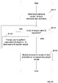
- Fig. 10 shows an illustrative flow chart for applying a set of calculated weight values to a set of luminance values for each photosite according to an embodiment of present disclosure. The entire process described in this flowchart is performed by processor 51.
- (u,v) refers to a coordinate of a photosite on a sensor array plane 13.
- step 111 processor 51 obtains luminance values from each photosite 131, 132, 133 to 13p captured with a lightfield camera 1 and is normalized.
- step 112 processor 51 accesses a storage (such as weight matrix storage 87) to obtain a set of weight values for the each photosite 131, 132, 133 to 13p, a set of weight values may be associated with present zoom/focus setting of lightfield camera 1.
- a storage such as weight matrix storage 87
- processor 51 accesses a storage (such as weight matrix storage 87) to obtain a set of weight values for the each photosite 131, 132, 133 to 13p, a set of weight values may be associated with present zoom/focus setting of lightfield camera 1.
- a storage such as weight matrix storage 87
- step 113 processor 51 prompts user to perform calculation of a set of weight values step described in Fig. 7 or Fig. 8 , or prompts user to register a set of weight values associated with present zoom/focus setting.
- a set of weight values can be obtained from the outer source such as internet or manufacturer's site.
- the prompt can be performed any ways known in the art such as by showing a message or outputting audio message through a MMI (Man Machine Interface) 85.
- MMI Man Machine Interface
- step 114 processor 51 multiplies luminance values from each photosite by the corresponding weight values.
- a calculated weight value w(u,v) may be used to multiply the luminance value of the photosite at location (u,v).
- the following secondary embodiment is related to adjusting sensitivities of each photosite with an additional hardware configuration.
- Fig. 11 shows illustrative configuration of a lightfield camera according to secondary embodiment of present disclosure.
- the difference from the lightfield camera 1 depicted in Fig. 1 is an image sensor array 13A comprising photosites 131A, 132A, 133A to 13pA of those sensitivities are respectively adjusted.
- Other configurations can be almost the same as with the lightfield camera 1 depicted in Fig. 1 .
- central photosites 132A which output relatively high luminance values will be designed to catch less photon by reducing the size of central photosite 132A or adjusting a fill factor of central photosite 132A by covering or hiding a surface of the photosite.
- an additional lens 21 may be required to be installed in order to set a center of image always located in the same position regardless of the zoom/focus settings since the hardware configurations of each photosite 131A, 132A, 133A to 13pA are changed.
- additional lens 21 may not be required as long as a lightfield camera 1A is a single-focus camera (in other words, in the case where a lightfield camera 1A does not have a functionality of zoom/focus settings, additional lens 21 may not be required.)
- secondary embodiment In contrast to first embodiment which relates to computationally changing luminance values by multiplying luminance values of each photosite 131, 132, 133 to 13p by corresponding weight values, secondary embodiment relates to adjusting sensitivities of each photosite 131A, 132A, 133A to 13pA by changing hardware configuration of each photosite 131A, 132A, 133A to 13pA.
- secondary embodiment is related to level the luminance values of photosites 131A, 132A, 133A to 13pA which aim to have the all the photosites 131A, 132A, 133A to 13pA outputs relatively the same luminance values for the captured Lambertian object image. This may be achieved by decreasing the sensitivities of central photosites 132A which catches more photons compared with the peripheral photosites 131A and 133A or increasing the sensitivities of peripheral photosites 131A and 133A.
- the secondary implementation of present disclosure is related to design (adjust) the sensitivities of the each photosite 131A, 132A, 133A to 13pA comprised in image sensor array 13A. Sensitivities of each photosite 131A, 132A, 133A to 13pA are adjusted in consideration of the respective weight values. The number of photons to be caught on each photosite 131A, 132A, 133A to 13pA may be proportional to the sizes or fill factors of each photosite 131A, 132A, 133A to 13pA.
- each photosite 131A, 132A, 133A to 13pA may be designed (adjusted) in accordance with the calculated a set of weight values for photosites 131, 132, 133 to 13p and 131A, 132A, 133A to 13pA.
- Fig. 12 shows an illustrative flow chart for calculating sets of weight values (weight matrix) for photosites according to a secondary embodiment of present disclosure. It is important to know that calculation of a set of weight values is performed using the other lightfield camera 1 that is depicted in Fig. 1 .
- Lightfield camera 1 has the same configuration as lightfield camera 1A which is depicted in Fig. 11 except for image sensor array 13.
- Image sensor array 13 of lightfield camera 1 which comprises photosites 131, 132, 133 to 13p of which sensitivities are not adjusted, in other word, the sensitivities of photosites 131, 132, 133 to 13p of lightfield camera 1 are homogeneous.
- lightfield camera 1 has the same photosite arrangement (the number of photosite and alignment) as the lightfield camera 1A.
- (u,v) refers to a coordinate of photosite on a sensor array plane 13 or 13A.
- step 121 lightfield camera 1 captures Lambertian object which radiates lights equally in all direction and send a signal to a processor 51.
- processor 51 obtains luminance values of the each photosite 131, 132, 133 to 13p of a lightfield camera 1 when a Lambertian object image is captured by the lightfield camera 1.
- the following table 1 shows an example of luminance value of 11x11 in total 121 photosites 131, 132, 133 to 13p corresponding to one microlense which locates at the center of the lenslet array 11.
- Table 1 0 1 2 3 4 5 6 7 8 9 10 0 0 0 1 3 5 6 5 3 1 0 0 1 0 2 6 12 19 22 19 12 6 2 0 2 1 6 16 34 52 60 52 34 16 6 1 3 3 12 34 70 107 124 107 70 34 12 3 4 5 19 52 107 165 190 165 107 52 19 5 5 6 22 60 124 190 220 190 124 60 22 6 6 5 19 52 107 165 190 165 107 52 19 5 7 3 12 34 70 107 124 107 70 34 12 3 8 1 6 16 34 52 60 52 34 16 6 1 9 0 2 6 12 19 22 19 12 6 2 0 10 0 0 1 3 5 6 5 3 1 0 0 0 0 0 0 0 0 0 0 0 2 6 12
- the maximum luminance value is 220.
- step 122 the luminance values of each photosite 131, 132, 133 to 13p may be normalized so that the maximum value to be transformed to the maximum magnitude that photosites can provide.
- Table 2 shows an example of normalized luminance value of 11x11 in total 121 photosites 131, 132, 133 to 13p corresponding to one microlense.
- Table 2 0 1 2 3 4 5 6 7 8 9 10 0 0.0 0.0 1.2 3.5 5.8 7.0 5.8 3.5 1.2 0.0 0.0 1 0.0 2.3 7.0 13.9 22.0 25.5 22.0 13.9 7.0 2.3 0.0 2 1.2 7.0 18.5 39.4 60.3 69.5 60.3 39.4 18.5 7.0 1.2 3 3.5 13.9 39.4 81.1 124.0 143.7 124.0 81.1 39.4 13.9 3.5 4 5.8 22.0 60.3 124.0 191.3 220.2 191.3 124.0 60.3 22.0 5.8 5 7.0 25.5 69.5 143.7 220.2 255.0 220.2 143.7 69.5 25.5 7.0 6 5.8 22.0 60.3 124.0 191.3 220.2 191.3 124.0 60.3 22.0 5.8 7 3.5 13.9 39.4 81.1 124.0 143.7 124.0 81.1 39.4 13.9 3.5 8 1.2 7.0 18.5
- step 123 processor 51 determines if a normalized luminance value of i-th photosite 131, 132, 133 to 13p is greater than or equal to a minimum threshold (min_threshold).
- min_threshold is arbitrary preset value and is stored in the memory.
- step 124 processor 51 calculates a weight value for i-th photosite 131, 132, 133 to 13p by dividing the minimum threshold (min_threshold) value by a luminance value of i-th photosite 131, 132, 133 to 13p if a luminance value of this i-th photosite 131, 132, 133 to 13p is greater than or equal to the minimum threshold (min_threshold).
- processor 51 registers calculated weight value for i-th photosite 131, 132, 133 to 13p to a memory in association with coordinate of a photosite 131, 132, 133 to 13p (u,v) on a sensor array plane 13. For example, processor 51 registers weight value w in association with the location of photosite ( u , v ) on a sensor array plane 13 so that its calculated weight value to be applied to the photosite 131A, 132A, 133A to 13pA of the same coordinate ( u , v ) on a sensor array plane 13A in a lightfield camera 1A.
- step 127 processor 51 set a weight value to "1" if it is determined that a luminance value of a photosite 131, 132, 133 to 13p is not greater than or equal to the minimum threshold (min_threshold).
- step 126 processor 51 determines whether this i-th photosite 131, 132, 133 to 13p is the last one or not.
- photosite to be processed is expressed in the form of i-th.
- a person skilled in the art may understand that the different form of calculation can be used.
- Adjustment of sensitivities of respective photosites 131A, 132A, 133A to 13pA can be implemented either by putting a cache partially hiding the receiving surface of each photosite 131A, 132A, 133A to 13pA or making a mask in front of each photosite 131A, 132A, 133A to 13pA to reduce the fill factors of each photosite 131A, 132A, 133A to 13pA.
- An alternative way to change the sensitivities of the photosites 131A, 132A, 133A to 13pA is designing a grey filter pattern and to print it (for instance by evaporation technique) onto the photosites 131A, 132A, 133A to 13pA, so that it attenuates the high values observed when capturing a white image.
- the camera exposure time can be increased. Increasing the exposure time may provide a brighter and vignetting-free image. That is, the exposure time can be adjusted in consideration of brightness of the captured image
- the peripheral photosites 131A, 132A, 133A to 13pA that are affected by the vignetting effect can be designed to catch more photon based on a set of weight values calculated by the steps (described in Fig. 7 and Fig. 8 ) described in first embodiment.
- the fill factors or sizes of peripheral photosites may be increased in consideration with calculated weight values.
- w ⁇ u v min_l ⁇ / max l ⁇ u v
- min_threshold max_1' refers to a normalized maximum luminance value that is transformed to the maximum magnitude that photosites can provide.
- l'(u,v) refers to a normalized luminance value of photosite located at the coordinate (u,v).
- minimum_surface is defined with the size or fill factor of central photosite which hit the luminance value 255 in the previously described table.
- Smax the maximum meaningful fill-factor
- Smin the minimum denoted by "Smin”
- the distance between the centers of two adjacent photosites are denoted by "PhotoSize” (The distance between each two adjacent photosite is assumed constant or homogeneous on the sensor array 13 to keep the formulation working).
- original Fill factor or size of a photosite at (u,v) is 0.5 of the size of PhotoSize.
- Fig. 13 shows an illustrative flow chart for calculating a set of fill factor or size of photosites f for photosites according to a secondary embodiment of present disclosure.
- step 131 (S131) lightfield camera 1 captures Lambertian object which radiates lights equally in all direction and send a signal to a processor 51.
- processor 51 obtains luminance values of the each of the photosites 131, 132, 133 to 13p of a lightfield camera 1 when a Lambertian object image is captured by the lightfield camera 1.
- step 133 processor 51 calculates a fill factor f for i-th photosite 131, 132, 133 to 13p with following formula.
- processor 51 registers calculated fill factor f for i-th photosite 131, 132, 133 to 13p to a memory in association with location of a photosite 131, 132, 133 to 13p (u,v) on a sensor array plane 13. For example, processor 51 registers fill factor f in association with the location of photosite ( u , v ) on a sensor array plane 13 so that its calculated fill factor f to be applied to the photosite 131A, 132A, 133A to 13pA of the same location ( u , v ) on a sensor array plane 13A in a lightfield camera 1A.
- step 135 processor 51 determines whether this i-th photosite 131, 132, 133 to 13p is the last one or not.
- processor 51 increments the photosite number i and go back to step 133 (S133). If this is the last photosite i max , process is terminated since a set of weight values (weight matrix) is calculated.
- photosite to be processed is expressed in the form of i-th.
- a person skilled in the art may understand that the different form of calculation can be used.
- An another variant implementation does not require adjusting exposure time since an image to be captured is overall bright with less noise compared with the embodiment which reduces the fill factor or sizes of photosites.
- Fig. 14 shows an illustrative flow chart for manufacturing an image sensor array that comprises a plurality of photosites according to an embodiment of present disclosure.
- processor 51 of another lightfield camera 1 obtains luminance values of the each photosite 131, 132, 133 to 13p when a Lambertian object image is captured by the lightfield camera 1.
- step 142 calculating a set of weight values (weight matrix) (or new fill factor) for correcting a vignetting effect to be caused on an image based on the captured Lambertian object image.
- step 143 manufacturing the image sensor array 13A which comprises the photosites 131A, 132A, 133A to 13pA having respective sensitivities adjusted in accordance with the calculated a set of weight values (or new fill factor) having associations with the each coordinate of photosites 131, 132, 133 to 13p of other lightfield camera 1.
- a weight value w (or new fill factor f ) is registered associated with a coordinates (u , v) of photosite 131, 132, 133 to 13p on a sensor array plane 13 in a lightfield camera 1.
- a lightfield camera 1 includes the same configuration as the lightfield camera 1A except that sensitivities of photosites 131, 132, 133 to 13p of lightfield camera 1 are not adjusted (in other word, sensitivities of photosites 131, 132, 133 to 13p of lightfield camera 1 are homogeneous.). Therefore a number and arrangement of photosites 131, 132, 133 to 13p of the other lightfield camera 1 are the same with the photosites 131A, 132A, 133A to 13pA of lightfield camera 1A.
- a user may download sets of weight values (sets of weight matrix) from the source outside or acquiring the sets of weight values by calibration steps detailed in this description, and registers the acquired sets of weight values into weight matrix storage 87.
- Weight matrix storage 87 stores sets of weight values each associated with respective zoom/focus setting. The system can find matching a set of weight values to present zoom/focus setting from the weight matrix storage 87 for correcting vignetting effect caused on an image captured by a lightfield camera 1. Therefore changing the luminance values of each photosite 131, 132, 133 to 13p will be effective to solve the technical problem stated in the section above.
- sensitivities of each photosite 131A, 132A, 133A to 13pA of a lightfield camera 1A are adjusted in accordance with the a set of calculated weight values using other lightfield camera 1.
- a lightfield camera 1A may further comprise an additional lens 21 which contributes to estimate one set of micro-image centers for every set of focusing-distance/zoom parameters of the lightfield camera 1. Therefore changing the sensitivities of each photosite 131A, 132A, 133A to 13pA will be effective to solve the technical problem stated in the section above.
- the present disclosure is not limited to the embodiments previously described.
- the present disclosure is not limited to a lightfield camera 1 or 1A but also extends to the method of controlling and/or calibrating the same and to the hardware circuitry implementing the controlling/calibration method.
- the method of correcting the vignetting effect caused on an image captured by a lightfield camera 1 or 1A described herein may be implemented by instructions being performed by a processor 51, and such instructions (and/or data values produced by an implementation) may be stored on a processor-readable medium such as, for example, an integrated circuit, a software carrier or other storage device such as, for example, a hard disk, a compact diskette (“CD”), an optical disc (such as, for example, a DVD, often referred to as a digital versatile disc or a digital video disc), a random access memory (“RAM”), or a read-only memory (“ROM”).
- the instructions may take the form of an application program tangibly embodied on a processor-readable medium.
- Instructions may be, for example, in hardware, firmware, software, or a combination. Instructions may be found in, for example, an operating system, a separate application, or a combination of the two.
- a processor 51 may be characterized, therefore, as, for example, both a device configured to carry out a process and a device that includes a processor-readable medium (such as a storage device) having instructions for carrying out a process. Further, a processor-readable medium may store, in addition to or in lieu of instructions, data values produced by an implementation.
- implementations may produce a variety of signals formatted to carry information that may be, for example, stored or transmitted.
- the information may include, for example, instructions for performing a method, or data produced by one of the described implementations.
- a signal may be formatted to carry as data the rules for writing or reading the syntax of a described embodiment, or to carry as data the actual syntax-values written by a described embodiment.
- Such a signal may be formatted, for example, as an electromagnetic wave (for example, using a radio frequency portion of spectrum) or as a baseband signal.
- the formatting may include, for example, encoding a data stream and modulating a carrier with the encoded data stream.
- the information that the signal carries may be, for example, analog or digital information.
- the signal may be transmitted over a variety of different wired or wireless links, as is known.
- the signal may be stored on a processor-readable medium.
Priority Applications (8)
| Application Number | Priority Date | Filing Date | Title |
|---|---|---|---|
| EP15307003.2A EP3182697A1 (de) | 2015-12-15 | 2015-12-15 | Verfahren und vorrichtung zur korrektur des vignettierungseffekts auf einem mit einer lichtfeldkamera aufgenommenen bild |
| JP2016242261A JP6978833B2 (ja) | 2015-12-15 | 2016-12-14 | ライトフィールドカメラによって取り込まれたイメージに生じる口径食効果を補正する方法及び装置 |
| EP16203918.4A EP3182698A3 (de) | 2015-12-15 | 2016-12-14 | Verfahren und vorrichtung zur korrektur des vignettierungseffekts auf einem mit einer lichtfeldkamera aufgenommenen bild |
| US15/379,710 US10455169B2 (en) | 2015-12-15 | 2016-12-15 | Method and apparatus for correcting vignetting effect caused on an image captured by lightfield cameras |
| KR1020160171582A KR20170074771A (ko) | 2015-12-15 | 2016-12-15 | 라이트필드 카메라들에 의해 캡처된 이미지 상에 야기된 비네팅 효과를 정정하는 방법 및 장치 |
| CN201611159809.4A CN107071233B (zh) | 2015-12-15 | 2016-12-15 | 一种用于对由光场照相机引起的渐晕效应进行校正的方法、设备和可读介质 |
| CN202110039317.6A CN112887637A (zh) | 2015-12-15 | 2016-12-15 | 校正光场照相机捕获的图像上引起的渐晕效应的方法和设备 |
| US16/510,715 US20210092314A1 (en) | 2015-12-15 | 2019-07-12 | Method and apparatus for correcting vignetting effect caused on an image captured by lightfield cameras |
Applications Claiming Priority (1)
| Application Number | Priority Date | Filing Date | Title |
|---|---|---|---|
| EP15307003.2A EP3182697A1 (de) | 2015-12-15 | 2015-12-15 | Verfahren und vorrichtung zur korrektur des vignettierungseffekts auf einem mit einer lichtfeldkamera aufgenommenen bild |
Publications (1)
| Publication Number | Publication Date |
|---|---|
| EP3182697A1 true EP3182697A1 (de) | 2017-06-21 |
Family
ID=55068930
Family Applications (2)
| Application Number | Title | Priority Date | Filing Date |
|---|---|---|---|
| EP15307003.2A Withdrawn EP3182697A1 (de) | 2015-12-15 | 2015-12-15 | Verfahren und vorrichtung zur korrektur des vignettierungseffekts auf einem mit einer lichtfeldkamera aufgenommenen bild |
| EP16203918.4A Withdrawn EP3182698A3 (de) | 2015-12-15 | 2016-12-14 | Verfahren und vorrichtung zur korrektur des vignettierungseffekts auf einem mit einer lichtfeldkamera aufgenommenen bild |
Family Applications After (1)
| Application Number | Title | Priority Date | Filing Date |
|---|---|---|---|
| EP16203918.4A Withdrawn EP3182698A3 (de) | 2015-12-15 | 2016-12-14 | Verfahren und vorrichtung zur korrektur des vignettierungseffekts auf einem mit einer lichtfeldkamera aufgenommenen bild |
Country Status (5)
| Country | Link |
|---|---|
| US (2) | US10455169B2 (de) |
| EP (2) | EP3182697A1 (de) |
| JP (1) | JP6978833B2 (de) |
| KR (1) | KR20170074771A (de) |
| CN (2) | CN107071233B (de) |
Cited By (1)
| Publication number | Priority date | Publication date | Assignee | Title |
|---|---|---|---|---|
| SE1950837A1 (en) * | 2019-07-03 | 2021-01-04 | Fingerprint Cards Ab | Sensor displacement compensation |
Families Citing this family (3)
| Publication number | Priority date | Publication date | Assignee | Title |
|---|---|---|---|---|
| CN110349132B (zh) * | 2019-06-25 | 2021-06-08 | 武汉纺织大学 | 一种基于光场相机深度信息提取的织物瑕疵检测方法 |
| CN111147760B (zh) * | 2019-12-23 | 2021-08-24 | 兴科迪智能科技(北京)有限公司 | 一种光场相机及其光度调整方法、装置及电子设备 |
| CN111970460B (zh) * | 2020-08-17 | 2022-05-20 | Oppo广东移动通信有限公司 | 高动态范围图像处理系统及方法、电子设备和可读存储介质 |
Citations (4)
| Publication number | Priority date | Publication date | Assignee | Title |
|---|---|---|---|---|
| US20030234864A1 (en) * | 2002-06-20 | 2003-12-25 | Matherson Kevin J. | Method and apparatus for producing calibration data for a digital camera |
| US20130022652A1 (en) * | 2007-07-11 | 2013-01-24 | Fertin Pharma A/S | Stable medicated chewing gum comprising cyclodextrin inclusion complex |
| US20150070537A1 (en) * | 2013-09-09 | 2015-03-12 | Apple Inc. | Lens Shading Modulation |
| US20150130907A1 (en) * | 2013-11-11 | 2015-05-14 | Samsung Electronics Co., Ltd. | Plenoptic camera device and shading correction method for the camera device |
Family Cites Families (33)
| Publication number | Priority date | Publication date | Assignee | Title |
|---|---|---|---|---|
| JPH06140612A (ja) * | 1992-10-28 | 1994-05-20 | Mitsubishi Electric Corp | 撮像素子及び撮像装置 |
| ES2165644T3 (es) * | 1993-05-05 | 2002-03-16 | Pierre Allio | Dispositivo de video autoestereoscopico. |
| US7502057B2 (en) | 2002-06-20 | 2009-03-10 | Hewlett-Packard Development Company, L.P. | Method and apparatus for color non-uniformity correction in a digital camera |
| US7391450B2 (en) * | 2002-08-16 | 2008-06-24 | Zoran Corporation | Techniques for modifying image field data |
| US7522967B2 (en) * | 2003-07-01 | 2009-04-21 | Hewlett-Packard Development Company, L.P. | Audio summary based audio processing |
| JP4388327B2 (ja) * | 2003-08-25 | 2009-12-24 | オリンパス株式会社 | 顕微鏡像撮像装置及び顕微鏡像撮像方法 |
| EP1602347A1 (de) * | 2004-06-04 | 2005-12-07 | Georges Magnin | Orthese zum Strecken des Kiefers. |
| CN101015197B (zh) * | 2004-06-07 | 2010-10-27 | 诺基亚公司 | 用于提高图像质量的方法和装置 |
| CN101426085B (zh) * | 2004-10-01 | 2012-10-03 | 小利兰·斯坦福大学托管委员会 | 成像装置及其方法 |
| JP2006253970A (ja) * | 2005-03-09 | 2006-09-21 | Ricoh Co Ltd | 撮像装置、シェーディング補正データ作成方法およびプログラム |
| JP4826152B2 (ja) * | 2005-06-23 | 2011-11-30 | 株式会社ニコン | 画像合成方法及び撮像装置 |
| JP5040662B2 (ja) * | 2006-02-03 | 2012-10-03 | 株式会社ニコン | 画像処理装置、画像処理方法、および画像処理プログラム |
| JP4487944B2 (ja) | 2006-02-09 | 2010-06-23 | ソニー株式会社 | 固体撮像装置 |
| US7834925B2 (en) * | 2006-06-05 | 2010-11-16 | Core Logic Inc. | Lens shading correction device and method in image sensor |
| CN100538264C (zh) * | 2006-11-17 | 2009-09-09 | 中国科学院上海光学精密机械研究所 | 单孔径多重成像的光学成像测距装置 |
| US20100265385A1 (en) * | 2009-04-18 | 2010-10-21 | Knight Timothy J | Light Field Camera Image, File and Configuration Data, and Methods of Using, Storing and Communicating Same |
| US8023758B2 (en) * | 2007-08-07 | 2011-09-20 | Qualcomm Incorporated | Surface mesh matching for lens roll-off correction |
| JP5354254B2 (ja) * | 2008-08-28 | 2013-11-27 | 株式会社ニコン | 形状測定装置及び方法、並びにプログラム |
| ATE551841T1 (de) * | 2009-04-22 | 2012-04-15 | Raytrix Gmbh | Digitales bildgebungsverfahren zum synthetisieren eines bildes unter verwendung der mit einer plenoptischen kamera aufgezeichneten daten |
| JP5351195B2 (ja) * | 2011-03-08 | 2013-11-27 | 株式会社東芝 | 固体撮像装置および携帯情報端末 |
| US9357831B2 (en) * | 2012-02-24 | 2016-06-07 | Vikan A/S | Hygienic brush head |
| US8948545B2 (en) * | 2012-02-28 | 2015-02-03 | Lytro, Inc. | Compensating for sensor saturation and microlens modulation during light-field image processing |
| JP5459337B2 (ja) * | 2012-03-21 | 2014-04-02 | カシオ計算機株式会社 | 撮像装置、画像処理方法及びプログラム |
| CN102692347A (zh) | 2012-05-08 | 2012-09-26 | 浙江工业大学 | 疲劳裂纹扩展试验摄像头自动调整图像采集装置及方法 |
| CN102739945B (zh) * | 2012-05-24 | 2014-09-03 | 上海理工大学 | 光场成像装置及方法 |
| JP2013258634A (ja) * | 2012-06-14 | 2013-12-26 | Canon Inc | 画像処理装置、画像処理方法、及びプログラム |
| CN104520745B (zh) * | 2012-08-06 | 2016-09-28 | 富士胶片株式会社 | 摄像装置 |
| JP6091176B2 (ja) * | 2012-11-19 | 2017-03-08 | キヤノン株式会社 | 画像処理方法、画像処理プログラム、画像処理装置および撮像装置 |
| KR20150054615A (ko) * | 2013-11-11 | 2015-05-20 | 삼성전자주식회사 | 플렌옵틱 카메라 장치 및 그의 세이딩 보정 방법 |
| JP2015144327A (ja) * | 2014-01-31 | 2015-08-06 | 株式会社 日立産業制御ソリューションズ | 撮像装置 |
| JP6418770B2 (ja) * | 2014-04-07 | 2018-11-07 | キヤノン株式会社 | 画像処理装置、撮像装置、画像処理方法、プログラム、および記憶媒体 |
| EP3104595A1 (de) * | 2015-06-08 | 2016-12-14 | Thomson Licensing | Lichtfeldabbildungsvorrichtung |
| EP3112920A1 (de) * | 2015-06-30 | 2017-01-04 | Thomson Licensing | Plenoptische kamera mit optischem anti-vignettierungsfilter und verfahren zur steuerung davon |
-
2015
- 2015-12-15 EP EP15307003.2A patent/EP3182697A1/de not_active Withdrawn
-
2016
- 2016-12-14 JP JP2016242261A patent/JP6978833B2/ja active Active
- 2016-12-14 EP EP16203918.4A patent/EP3182698A3/de not_active Withdrawn
- 2016-12-15 CN CN201611159809.4A patent/CN107071233B/zh active Active
- 2016-12-15 US US15/379,710 patent/US10455169B2/en active Active
- 2016-12-15 KR KR1020160171582A patent/KR20170074771A/ko not_active Application Discontinuation
- 2016-12-15 CN CN202110039317.6A patent/CN112887637A/zh active Pending
-
2019
- 2019-07-12 US US16/510,715 patent/US20210092314A1/en not_active Abandoned
Patent Citations (4)
| Publication number | Priority date | Publication date | Assignee | Title |
|---|---|---|---|---|
| US20030234864A1 (en) * | 2002-06-20 | 2003-12-25 | Matherson Kevin J. | Method and apparatus for producing calibration data for a digital camera |
| US20130022652A1 (en) * | 2007-07-11 | 2013-01-24 | Fertin Pharma A/S | Stable medicated chewing gum comprising cyclodextrin inclusion complex |
| US20150070537A1 (en) * | 2013-09-09 | 2015-03-12 | Apple Inc. | Lens Shading Modulation |
| US20150130907A1 (en) * | 2013-11-11 | 2015-05-14 | Samsung Electronics Co., Ltd. | Plenoptic camera device and shading correction method for the camera device |
Non-Patent Citations (1)
| Title |
|---|
| N. SABATER; M. SEIFI; V. DRAZIC; G. SANDRI; P. PEREZ, ACCURATE DISPARITY ESTIMATION FOR PLENOPTIC IMAGES, 20 March 2015 (2015-03-20), Retrieved from the Internet <URL:http://link.springer.com/article/10.1007%2F978-3-319-16181-5 42/lookinside/000.png> |
Cited By (3)
| Publication number | Priority date | Publication date | Assignee | Title |
|---|---|---|---|---|
| SE1950837A1 (en) * | 2019-07-03 | 2021-01-04 | Fingerprint Cards Ab | Sensor displacement compensation |
| WO2021002791A1 (en) * | 2019-07-03 | 2021-01-07 | Fingerprint Cards Ab | Sensor displacement compensation in an optical biometric imaging arrangment under a display |
| US11657642B2 (en) | 2019-07-03 | 2023-05-23 | Fingerprint Cards Anacatum Ip Ab | Sensor displacement compensation in an optical biometric imaging arrangement under a display |
Also Published As
| Publication number | Publication date |
|---|---|
| EP3182698A2 (de) | 2017-06-21 |
| EP3182698A3 (de) | 2017-08-23 |
| JP2017139743A (ja) | 2017-08-10 |
| CN107071233A (zh) | 2017-08-18 |
| CN112887637A (zh) | 2021-06-01 |
| US20210092314A1 (en) | 2021-03-25 |
| JP6978833B2 (ja) | 2021-12-08 |
| KR20170074771A (ko) | 2017-06-30 |
| CN107071233B (zh) | 2021-01-29 |
| US10455169B2 (en) | 2019-10-22 |
| US20170171479A1 (en) | 2017-06-15 |
Similar Documents
| Publication | Publication Date | Title |
|---|---|---|
| US20210092314A1 (en) | Method and apparatus for correcting vignetting effect caused on an image captured by lightfield cameras | |
| US10630906B2 (en) | Imaging control method, electronic device and computer readable storage medium | |
| US8004566B2 (en) | Self calibration of white balance for a digital camera device using correlated color temperature data | |
| CN106067953B (zh) | 确定用于具有各种视场的多相机设备的镜头阴影校正的方法和装置 | |
| US20140078247A1 (en) | Image adjuster and image adjusting method and program | |
| US8520081B2 (en) | Imaging device and method, and image processing method for imaging device | |
| US8463068B2 (en) | Methods, systems and apparatuses for pixel value correction using multiple vertical and/or horizontal correction curves | |
| US20100328456A1 (en) | Lenslet camera parallax correction using distance information | |
| US20160125611A1 (en) | Depth measurement apparatus, imaging apparatus and depth measurement method | |
| US20130342751A1 (en) | Image pickup apparatus and its control method | |
| WO2014171304A1 (ja) | 撮像装置、撮像装置駆動方法、撮像装置制御プログラム | |
| JP2015220716A (ja) | 撮像素子、その制御方法、および制御プログラム、並びに信号処理装置 | |
| US20180115757A1 (en) | Mesh-based auto white balancing | |
| US8547440B2 (en) | Image correction for image capturing with an optical image stabilizer | |
| US10972676B2 (en) | Image processing method and electronic device capable of optimizing hdr image by using depth information | |
| JP6555990B2 (ja) | 距離計測装置、撮像装置、および距離計測方法 | |
| CN113542709A (zh) | 投影图像亮度调整方法、装置、存储介质及投影设备 | |
| KR101337667B1 (ko) | 휘도 정보에 기초하여 보정된 값들을 이용한 렌즈 롤 오프 보정 동작 | |
| KR101797080B1 (ko) | 카메라 모듈 및 그의 렌즈 쉐이딩 교정 방법 | |
| US8154618B2 (en) | Imaging apparatus and method for setting the same | |
| JP6348883B2 (ja) | 画像撮像装置、画像撮像方法及びコンピュータプログラム | |
| CN115278001A (zh) | 图像传感器、摄像头模组、电子设备及拍摄方法 | |
| JP2019106215A (ja) | データ処理装置、撮像装置、およびデータ処理方法 | |
| JP2016194956A (ja) | データ処理装置、撮像装置、およびデータ処理方法 | |
| TWM516732U (zh) | 涵蓋景深之調焦系統 |
Legal Events
| Date | Code | Title | Description |
|---|---|---|---|
| PUAI | Public reference made under article 153(3) epc to a published international application that has entered the european phase |
Free format text: ORIGINAL CODE: 0009012 |
|
| AK | Designated contracting states |
Kind code of ref document: A1 Designated state(s): AL AT BE BG CH CY CZ DE DK EE ES FI FR GB GR HR HU IE IS IT LI LT LU LV MC MK MT NL NO PL PT RO RS SE SI SK SM TR |
|
| AX | Request for extension of the european patent |
Extension state: BA ME |
|
| STAA | Information on the status of an ep patent application or granted ep patent |
Free format text: STATUS: THE APPLICATION IS DEEMED TO BE WITHDRAWN |
|
| 18D | Application deemed to be withdrawn |
Effective date: 20171222 |