EP3182437A2 - Klappanker mit gekrümmter polfläche - Google Patents
Klappanker mit gekrümmter polfläche Download PDFInfo
- Publication number
- EP3182437A2 EP3182437A2 EP16204353.3A EP16204353A EP3182437A2 EP 3182437 A2 EP3182437 A2 EP 3182437A2 EP 16204353 A EP16204353 A EP 16204353A EP 3182437 A2 EP3182437 A2 EP 3182437A2
- Authority
- EP
- European Patent Office
- Prior art keywords
- pole face
- core
- armature
- curvature
- core surface
- Prior art date
- Legal status (The legal status is an assumption and is not a legal conclusion. Google has not performed a legal analysis and makes no representation as to the accuracy of the status listed.)
- Granted
Links
Images





Classifications
-
- H—ELECTRICITY
- H01—ELECTRIC ELEMENTS
- H01H—ELECTRIC SWITCHES; RELAYS; SELECTORS; EMERGENCY PROTECTIVE DEVICES
- H01H50/00—Details of electromagnetic relays
- H01H50/16—Magnetic circuit arrangements
- H01H50/18—Movable parts of magnetic circuits, e.g. armature
- H01H50/24—Parts rotatable or rockable outside coil
-
- H—ELECTRICITY
- H01—ELECTRIC ELEMENTS
- H01H—ELECTRIC SWITCHES; RELAYS; SELECTORS; EMERGENCY PROTECTIVE DEVICES
- H01H50/00—Details of electromagnetic relays
- H01H50/16—Magnetic circuit arrangements
- H01H50/18—Movable parts of magnetic circuits, e.g. armature
- H01H50/24—Parts rotatable or rockable outside coil
- H01H50/26—Parts movable about a knife edge
-
- H—ELECTRICITY
- H01—ELECTRIC ELEMENTS
- H01H—ELECTRIC SWITCHES; RELAYS; SELECTORS; EMERGENCY PROTECTIVE DEVICES
- H01H50/00—Details of electromagnetic relays
- H01H50/16—Magnetic circuit arrangements
- H01H50/36—Stationary parts of magnetic circuit, e.g. yoke
-
- H—ELECTRICITY
- H01—ELECTRIC ELEMENTS
- H01H—ELECTRIC SWITCHES; RELAYS; SELECTORS; EMERGENCY PROTECTIVE DEVICES
- H01H50/00—Details of electromagnetic relays
- H01H50/54—Contact arrangements
- H01H50/546—Contact arrangements for contactors having bridging contacts
-
- H—ELECTRICITY
- H01—ELECTRIC ELEMENTS
- H01H—ELECTRIC SWITCHES; RELAYS; SELECTORS; EMERGENCY PROTECTIVE DEVICES
- H01H50/00—Details of electromagnetic relays
- H01H50/54—Contact arrangements
- H01H50/56—Contact spring sets
-
- H—ELECTRICITY
- H01—ELECTRIC ELEMENTS
- H01H—ELECTRIC SWITCHES; RELAYS; SELECTORS; EMERGENCY PROTECTIVE DEVICES
- H01H50/00—Details of electromagnetic relays
- H01H50/54—Contact arrangements
- H01H50/56—Contact spring sets
- H01H50/58—Driving arrangements structurally associated therewith; Mounting of driving arrangements on armature
-
- H—ELECTRICITY
- H01—ELECTRIC ELEMENTS
- H01H—ELECTRIC SWITCHES; RELAYS; SELECTORS; EMERGENCY PROTECTIVE DEVICES
- H01H50/00—Details of electromagnetic relays
- H01H50/64—Driving arrangements between movable part of magnetic circuit and contact
- H01H50/641—Driving arrangements between movable part of magnetic circuit and contact intermediate part performing a rectilinear movement
-
- H—ELECTRICITY
- H01—ELECTRIC ELEMENTS
- H01H—ELECTRIC SWITCHES; RELAYS; SELECTORS; EMERGENCY PROTECTIVE DEVICES
- H01H50/00—Details of electromagnetic relays
- H01H50/64—Driving arrangements between movable part of magnetic circuit and contact
- H01H50/643—Driving arrangements between movable part of magnetic circuit and contact intermediate part performing a rotating or pivoting movement
-
- H—ELECTRICITY
- H01—ELECTRIC ELEMENTS
- H01H—ELECTRIC SWITCHES; RELAYS; SELECTORS; EMERGENCY PROTECTIVE DEVICES
- H01H51/00—Electromagnetic relays
- H01H51/22—Polarised relays
- H01H51/2272—Polarised relays comprising rockable armature, rocking movement around central axis parallel to the main plane of the armature
Definitions
- the invention relates generally to electromechanical switching devices such as relays or contactors. More particularly the invention relates to the armature or stator that is a part of the actuating mechanism.
- the clapper mechanism is named as it functions in a manner similar to that of clapping hands.
- One hand is movable and is called the armature.
- the armature is drawn by magnetic force to the second hand which is stationary and is referred to as the stator or core.
- An electromagnetic field is induced into the stator through the use of a coil that can be excited by either direct current (DC) or alternating current (AC).
- DC direct current
- AC alternating current
- Application of a voltage to the coil will result in an electromagnetic field being induced in the stator which will attract the armature as the armature is comprised of a ferromagnetic material.
- open and closed are in relation to the electrical contacts that are operated by the clapper mechanism where the electrical contacts being controlled are commonly referred to as either Normally Open (NO) or Normally Closed (NC).
- NO Normally Open
- NC Normally Closed
- open and closed will refer to the state of the clapper mechanism, not the electrical contacts that may be controlled by the device.
- Clapper mechanisms are designed with planar armature plates and planar stator cores that move about a fixed fulcrum point on the bottom of the armature plate.
- an electromagnetic field is created in the stator, and the armature is attracted to the stator and moves toward it until it comes to rest upon contacting the face of the stator.
- the armature is held in this position by electromagnetic force until such time when the coil is de-energized at which point the electromagnetic field collapses and the armature returns to the open state under the influence of the return mechanism.
- the voltage at which the coil is energized is referred to as the "pull-in” voltage and the voltage at which the coil is de-energized is referred to as the "drop-out” voltage.
- the coil voltage induces an electromagnetic field in the coil and in turn the stator, thus below the pull-in voltage the electromagnetic field is insufficient to overcome the mass, friction, and return mechanism of the armature and move it into the closed position.
- the pull-in voltage there will be sufficient electromagnetic field to overcome these elements and the clapper armature will be moved to the closed state.
- the electromagnetic field must decrease to a point at which it can be overcome by the return mechanism and thus move the armature away from the stator pole face to the open position.
- planar armature In the open position the planar armature is positioned with an inclination of a few degrees in relation to the flat pole face of the stator or core. This relationship describes a triangular shaped volume of air and defines the amount of travel required to close the clapper mechanism. Due to the size of the volume of air in the case where both the armature and stator have a planar face, the pull-in voltage must be high enough to generate an electromagnetic field sufficient to initiate the closing of the mechanism. The magnetic field starts out relatively weak though sufficient to initiate movement so the initial closing force is relatively low. However, as the armature moves toward the flat pole face of the stator the magnetic field rapidly increases and in turn the closing force until the armature contacts the pole face of the stator in the closed position. A problem with typical planar faced armature and stator embodiments is that this rapid increase of closing force overshoots the level required to close the clapper mechanism resulting in undesired wear and a decrease in the mechanical life of the device.
- the magnetic field When the clapper mechanism is closed the magnetic field is at its strongest. Unfortunately the strength of the magnetic field in the closed state requires the drop-out voltage of the coil to fall to a very low level in order to allow the return mechanism to overcome the electromagnetic field and move the armature to the open state. The longer it takes for the coil to become de-energized the longer an electrical circuit that is being controlled by the contacts associated with the electromechanical switching device remain energized consequently presenting a potentially hazardous state to people or devices in addition to decreasing the service life of the device due to longer arcing times until the clapper mechanism moves to the open state and in turn de-energizes any circuits associated with the electromechanical switching device.
- the embodiments in the present disclosure provide a novel technique for increasing the force between the armature and the core of an electromechanical switching device resulting in the reduction of the required pull-in voltage. Additionally the remnant or holding force of the closed armature is reduced which results in increased dropout voltage allowing the electromechanical switching device to open more quickly when the control voltage has been removed.
- a circuit interrupting device is illustrated in the form of a three-pole contactor 10 for controlling electrical current carrying paths for three separate circuits.
- the contactor 10 includes an upper housing 12 and a lower housing 14.
- Upper housing 12 hosts one or more sets of electrically isolated contacts contained within the assembly.
- Line terminals 22 are used to connect line input wires 16 to each contact set.
- Load terminals 24 are used to connect contact outputs to the load output wires 18.
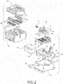
- coil terminals 26 for the connection of the wires 20 that provide the electrical connection for the application of the control voltage to the stator coil 32 illustrated in Fig. 2 .
- Upper housing 12 comprises a cover 44, a set of line terminals with fixed contacts 50 and associated line terminal block screws 46, a set of load terminals with fixed contacts 52 and associated load terminal block screws 48, a set of auxiliary terminals and fixed contacts 56 and associated auxiliary terminal block screws 54 all of which are contained within the contact housing 42.
- Contact housing 42 provides electrical isolation between individual terminals and contacts.
- Crossbar assembly 34 is transversely oriented on an axis perpendicular to that of the axis formed by the line terminals with fixed contacts 50, the load terminals with fixed contacts 52, and the auxiliary terminals with fixed contacts 56 such that lateral movement of crossbar assembly 34 will complete electrical circuits by the movement of moveable line contacts 72, moveable load contacts, and moveable auxiliary contacts 74 into contact with their associated fixed contacts.
- Return spring 36 will return contact assembly 34 and associated moveable contacts to the open state in turn opening the associated electrical circuits.
- lower housing 14 comprises middle plate 40 which is positioned below contact housing 42 and crossbar assembly 34 and provides arc containment and electrical isolation to stator coil 32 and stator core 30.
- Stator core 30 is inserted into stator coil slot 68 of stator coil 32 and in turn lower housing 14.
- Armature 62 is positioned in lower housing 14 in free supported relation to the lower stator core face 58 and upper stator core face 60.
- Stator coil 32 comprises a set of electrical windings whose ends are connected to coil terminals 26 such that the connection of an electrical current to coil terminals 26 energizes stator coil 32 and causes the formation of an electromagnetic field which is concentrated by stator core 30.
- stator core 30 results in a rolling movement having a shifting center point of armature 62 towards stator core 30.
- Movement of armature 62 causes movement of crossbar assembly 34 by the engagement of crossbar engagement arm 64 with actuator slot 38 of crossbar assembly 34 completing electrical circuits by the movement of moveable line contacts 72, moveable load contacts 70, and moveable auxiliary contacts 74 into contact with their associated fixed contacts.
- the removal of electrical current from coil terminals 26 de-energizes stator coil 32 causing the collapse of the electromagnetic field in stator coil 32 and stator core 30 and with the loss of the electromagnetic field, the loss of the associated attraction of armature 62, and thus crossbar assembly 34 is returned to its de-energized state by return spring 36.
- Lower housing 14 has a generally rectangular base providing a slot 28 therein for receiving a standard DIN rail along the transverse axis generally within the plane of the base.
- FIG. 3A and Fig. 3B bottom views of the upper housing 12 of the contactor of Fig. 1 are shown depicting the contactor in a de-energized state in Fig. 3A and an energized state in Fig. 3B .
- energizing stator coil 32 and the associated electromagnetic field formed by stator core 30 results in the movement of armature 62 and crossbar engagement arm 64 which is engaged with actuator slot 38 of crossbar assembly 34 causing its subsequent motion and the completion of electrical circuits by the movement of moveable line contacts 72, moveable load contacts 70, and moveable auxiliary contacts 74 into contact with their associated fixed contacts, line terminal block and contact 50, load terminal block and contact 52, and auxiliary terminal block and contact 56.
- return spring 36 Upon removal of the electrical current from coil terminals 26 and the loss of the electromagnetic field of stator coil 32 and stator core 30, returns crossbar assembly 34 and armature 62 to a de-energized state.
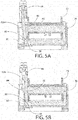
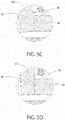
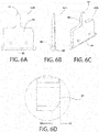
- Fig. 4A through Fig. 4D depict various views of an embodiment of the invention in which, armature 62A has a radius pole face 82. Adding a radius to the pole face 82 has the effect of reducing the volume of air at the point of engagement between the radius pole face 82 and the lower stator core face 58 as illustrated in Fig. 5A with additional detail in Fig. 5C .
- Reducing the volume of air in the open or de-energized state causes an increase in the magnetic flux and associated magnetic force resulting in a reduced pull-in voltage when stator coil 32 is energized.
- the effect of the radius pole face 82 is to increase the volume of air at the joint between the radius pole face 82 and the lower stator core face 58 as illustrated in Fig. 5B with additional detail in Fig. 5D . Therefore the magnetic flux and associated magnetic force is reduced which results in a higher dropout voltage with the additional benefit that the introduction of radius pole face 82 with its associated rolling movement having a shifting center point changes the lever arm of the armature pole face 82 resulting in decreased closing force which in turn increases the service life of circuit interrupting device 10.
- a similar result can be achieved by adding a radius to the lower stator core face 58, or in a combination with radius pole face 82 wherein both surfaces have a radius.
- armature 62B has an involute pole face 88 as detailed in Fig, 6D .
- the involute pole face 88 provides improvement in an increased drop-out voltage, decreased pull-in voltage, and further decreased closing force over that of the radius pole face 82.
- improved results can be achieved by adding an involute curve to the lower stator core face 58, or in a combination with involute pole face 88 wherein both surfaces have an involute curve.
- various curved surfaces may be modeled and developed by the iteration of numerous planar surfaces in an arrangement that approximates a curved surface providing similar benefits as described.
Landscapes
- Physics & Mathematics (AREA)
- Electromagnetism (AREA)
- Electromagnets (AREA)
- Breakers (AREA)
Applications Claiming Priority (1)
| Application Number | Priority Date | Filing Date | Title |
|---|---|---|---|
| US14/971,580 US9916953B2 (en) | 2015-12-16 | 2015-12-16 | Clapper armature with curved pole face |
Publications (3)
| Publication Number | Publication Date |
|---|---|
| EP3182437A2 true EP3182437A2 (de) | 2017-06-21 |
| EP3182437A3 EP3182437A3 (de) | 2017-07-26 |
| EP3182437B1 EP3182437B1 (de) | 2021-07-21 |
Family
ID=57570209
Family Applications (1)
| Application Number | Title | Priority Date | Filing Date |
|---|---|---|---|
| EP16204353.3A Active EP3182437B1 (de) | 2015-12-16 | 2016-12-15 | Klappanker mit gekrümmter polfläche |
Country Status (2)
| Country | Link |
|---|---|
| US (1) | US9916953B2 (de) |
| EP (1) | EP3182437B1 (de) |
Families Citing this family (1)
| Publication number | Priority date | Publication date | Assignee | Title |
|---|---|---|---|---|
| CN119340162A (zh) * | 2023-07-21 | 2025-01-21 | 施耐德电气工业公司 | 运动机构及相应的接触器 |
Family Cites Families (10)
| Publication number | Priority date | Publication date | Assignee | Title |
|---|---|---|---|---|
| CH445605A (de) * | 1966-06-17 | 1967-10-31 | Metall Invent Sa | Elektromagnetisches Betätigungsgerät |
| DE2558065C3 (de) | 1975-12-22 | 1981-01-15 | Siemens Ag, 1000 Berlin Und 8000 Muenchen | Ankerlagerung für ein elektromagnetisches Relais |
| AT397004B (de) | 1987-07-20 | 1994-01-25 | Schrack Elektronik Ag | Ankerlagerung für ein elektromechanisches relais |
| EP0579832B1 (de) * | 1991-04-09 | 1999-10-06 | Omron Corporation | Elektromagnetisches relais |
| US5646588A (en) | 1994-09-19 | 1997-07-08 | Caterpillar Inc. | Stroke elongation device for an electromagnetic actuator |
| AT412433B (de) * | 2000-05-11 | 2005-02-25 | Felten & Guilleaume Kg | Elektromechanischer fernschalter |
| US7053742B2 (en) | 2001-12-28 | 2006-05-30 | Abb Technology Ag | Electromagnetic actuator having a high initial force and improved latching |
| US6798322B2 (en) * | 2002-06-17 | 2004-09-28 | Tyco Electronics Corporation | Low noise relay |
| DE102011081854A1 (de) | 2011-08-31 | 2013-02-28 | Siemens Aktiengesellschaft | Vorrichtung zur Lagerung eines Klappankers |
| US8502627B1 (en) | 2012-09-19 | 2013-08-06 | International Controls And Measurements Corporation | Relay with stair-structured pole faces |
-
2015
- 2015-12-16 US US14/971,580 patent/US9916953B2/en active Active
-
2016
- 2016-12-15 EP EP16204353.3A patent/EP3182437B1/de active Active
Non-Patent Citations (1)
| Title |
|---|
| None |
Also Published As
| Publication number | Publication date |
|---|---|
| US9916953B2 (en) | 2018-03-13 |
| EP3182437B1 (de) | 2021-07-21 |
| EP3182437A3 (de) | 2017-07-26 |
| US20170178849A1 (en) | 2017-06-22 |
Similar Documents
| Publication | Publication Date | Title |
|---|---|---|
| US10199193B2 (en) | Electromagnetic relay | |
| JP6528271B2 (ja) | 接点装置および電磁継電器 | |
| US9704683B2 (en) | Double-break relay | |
| US2476794A (en) | Contactor | |
| KR101626365B1 (ko) | 회로 차단기용 액츄에이터 및 그 제조방법 | |
| JP4281251B2 (ja) | 電磁継電器 | |
| EP2859571B1 (de) | Elektrische schaltvorrichtung und relais mit ferromagnetischem oder magnetischem anker mit einem konischen teil | |
| EP3182437B1 (de) | Klappanker mit gekrümmter polfläche | |
| KR100988131B1 (ko) | 진공차단기용 영구자석 액튜에이터 | |
| JP4761913B2 (ja) | 電磁アクチュエータ | |
| JP7107169B2 (ja) | リレー | |
| JP2017135050A (ja) | 電磁継電器 | |
| JP4975319B2 (ja) | 真空遮断器 | |
| US3588765A (en) | Electromagnetic relays | |
| US11373830B2 (en) | Electromagnetic relay to ensure stable energization even when contact is dissolved | |
| JP2019117809A (ja) | 接点装置および電磁継電器 | |
| US1449212A (en) | Controlling means | |
| JP2003016888A (ja) | 電力用開閉装置の操作装置 | |
| WO2020148994A1 (ja) | リレー | |
| US2542835A (en) | Electromagnetic contactor | |
| JP5820993B2 (ja) | 電磁石装置およびこれを用いた電磁リレー | |
| JP2006196372A (ja) | パワーリレー | |
| GB289474A (en) | Improvements in or relating to circuit interrupters | |
| US3363203A (en) | Bistable operating reed relay | |
| US3491316A (en) | Electromagnetic contactors |
Legal Events
| Date | Code | Title | Description |
|---|---|---|---|
| PUAI | Public reference made under article 153(3) epc to a published international application that has entered the european phase |
Free format text: ORIGINAL CODE: 0009012 |
|
| STAA | Information on the status of an ep patent application or granted ep patent |
Free format text: STATUS: THE APPLICATION HAS BEEN PUBLISHED |
|
| AK | Designated contracting states |
Kind code of ref document: A2 Designated state(s): AL AT BE BG CH CY CZ DE DK EE ES FI FR GB GR HR HU IE IS IT LI LT LU LV MC MK MT NL NO PL PT RO RS SE SI SK SM TR |
|
| AX | Request for extension of the european patent |
Extension state: BA ME |
|
| REG | Reference to a national code |
Ref country code: DE Ref legal event code: R079 Ref document number: 602016060854 Country of ref document: DE Free format text: PREVIOUS MAIN CLASS: H01H0050640000 Ipc: H01H0050240000 |
|
| PUAL | Search report despatched |
Free format text: ORIGINAL CODE: 0009013 |
|
| AK | Designated contracting states |
Kind code of ref document: A3 Designated state(s): AL AT BE BG CH CY CZ DE DK EE ES FI FR GB GR HR HU IE IS IT LI LT LU LV MC MK MT NL NO PL PT RO RS SE SI SK SM TR |
|
| AX | Request for extension of the european patent |
Extension state: BA ME |
|
| RIC1 | Information provided on ipc code assigned before grant |
Ipc: H01F 7/14 20060101ALI20170621BHEP Ipc: H01H 50/24 20060101AFI20170621BHEP Ipc: H01H 50/54 20060101ALI20170621BHEP Ipc: H01H 50/64 20060101ALI20170621BHEP |
|
| STAA | Information on the status of an ep patent application or granted ep patent |
Free format text: STATUS: REQUEST FOR EXAMINATION WAS MADE |
|
| 17P | Request for examination filed |
Effective date: 20171127 |
|
| RBV | Designated contracting states (corrected) |
Designated state(s): AL AT BE BG CH CY CZ DE DK EE ES FI FR GB GR HR HU IE IS IT LI LT LU LV MC MK MT NL NO PL PT RO RS SE SI SK SM TR |
|
| GRAP | Despatch of communication of intention to grant a patent |
Free format text: ORIGINAL CODE: EPIDOSNIGR1 |
|
| STAA | Information on the status of an ep patent application or granted ep patent |
Free format text: STATUS: GRANT OF PATENT IS INTENDED |
|
| INTG | Intention to grant announced |
Effective date: 20210222 |
|
| GRAS | Grant fee paid |
Free format text: ORIGINAL CODE: EPIDOSNIGR3 |
|
| GRAA | (expected) grant |
Free format text: ORIGINAL CODE: 0009210 |
|
| STAA | Information on the status of an ep patent application or granted ep patent |
Free format text: STATUS: THE PATENT HAS BEEN GRANTED |
|
| AK | Designated contracting states |
Kind code of ref document: B1 Designated state(s): AL AT BE BG CH CY CZ DE DK EE ES FI FR GB GR HR HU IE IS IT LI LT LU LV MC MK MT NL NO PL PT RO RS SE SI SK SM TR |
|
| REG | Reference to a national code |
Ref country code: GB Ref legal event code: FG4D |
|
| REG | Reference to a national code |
Ref country code: CH Ref legal event code: EP |
|
| REG | Reference to a national code |
Ref country code: DE Ref legal event code: R096 Ref document number: 602016060854 Country of ref document: DE |
|
| REG | Reference to a national code |
Ref country code: AT Ref legal event code: REF Ref document number: 1413365 Country of ref document: AT Kind code of ref document: T Effective date: 20210815 |
|
| REG | Reference to a national code |
Ref country code: IE Ref legal event code: FG4D |
|
| REG | Reference to a national code |
Ref country code: LT Ref legal event code: MG9D |
|
| REG | Reference to a national code |
Ref country code: NL Ref legal event code: MP Effective date: 20210721 |
|
| REG | Reference to a national code |
Ref country code: AT Ref legal event code: MK05 Ref document number: 1413365 Country of ref document: AT Kind code of ref document: T Effective date: 20210721 |
|
| PG25 | Lapsed in a contracting state [announced via postgrant information from national office to epo] |
Ref country code: RS Free format text: LAPSE BECAUSE OF FAILURE TO SUBMIT A TRANSLATION OF THE DESCRIPTION OR TO PAY THE FEE WITHIN THE PRESCRIBED TIME-LIMIT Effective date: 20210721 Ref country code: SE Free format text: LAPSE BECAUSE OF FAILURE TO SUBMIT A TRANSLATION OF THE DESCRIPTION OR TO PAY THE FEE WITHIN THE PRESCRIBED TIME-LIMIT Effective date: 20210721 Ref country code: HR Free format text: LAPSE BECAUSE OF FAILURE TO SUBMIT A TRANSLATION OF THE DESCRIPTION OR TO PAY THE FEE WITHIN THE PRESCRIBED TIME-LIMIT Effective date: 20210721 Ref country code: FI Free format text: LAPSE BECAUSE OF FAILURE TO SUBMIT A TRANSLATION OF THE DESCRIPTION OR TO PAY THE FEE WITHIN THE PRESCRIBED TIME-LIMIT Effective date: 20210721 Ref country code: ES Free format text: LAPSE BECAUSE OF FAILURE TO SUBMIT A TRANSLATION OF THE DESCRIPTION OR TO PAY THE FEE WITHIN THE PRESCRIBED TIME-LIMIT Effective date: 20210721 Ref country code: NL Free format text: LAPSE BECAUSE OF FAILURE TO SUBMIT A TRANSLATION OF THE DESCRIPTION OR TO PAY THE FEE WITHIN THE PRESCRIBED TIME-LIMIT Effective date: 20210721 Ref country code: NO Free format text: LAPSE BECAUSE OF FAILURE TO SUBMIT A TRANSLATION OF THE DESCRIPTION OR TO PAY THE FEE WITHIN THE PRESCRIBED TIME-LIMIT Effective date: 20211021 Ref country code: PT Free format text: LAPSE BECAUSE OF FAILURE TO SUBMIT A TRANSLATION OF THE DESCRIPTION OR TO PAY THE FEE WITHIN THE PRESCRIBED TIME-LIMIT Effective date: 20211122 Ref country code: LT Free format text: LAPSE BECAUSE OF FAILURE TO SUBMIT A TRANSLATION OF THE DESCRIPTION OR TO PAY THE FEE WITHIN THE PRESCRIBED TIME-LIMIT Effective date: 20210721 Ref country code: AT Free format text: LAPSE BECAUSE OF FAILURE TO SUBMIT A TRANSLATION OF THE DESCRIPTION OR TO PAY THE FEE WITHIN THE PRESCRIBED TIME-LIMIT Effective date: 20210721 Ref country code: BG Free format text: LAPSE BECAUSE OF FAILURE TO SUBMIT A TRANSLATION OF THE DESCRIPTION OR TO PAY THE FEE WITHIN THE PRESCRIBED TIME-LIMIT Effective date: 20211021 |
|
| PG25 | Lapsed in a contracting state [announced via postgrant information from national office to epo] |
Ref country code: PL Free format text: LAPSE BECAUSE OF FAILURE TO SUBMIT A TRANSLATION OF THE DESCRIPTION OR TO PAY THE FEE WITHIN THE PRESCRIBED TIME-LIMIT Effective date: 20210721 Ref country code: LV Free format text: LAPSE BECAUSE OF FAILURE TO SUBMIT A TRANSLATION OF THE DESCRIPTION OR TO PAY THE FEE WITHIN THE PRESCRIBED TIME-LIMIT Effective date: 20210721 Ref country code: GR Free format text: LAPSE BECAUSE OF FAILURE TO SUBMIT A TRANSLATION OF THE DESCRIPTION OR TO PAY THE FEE WITHIN THE PRESCRIBED TIME-LIMIT Effective date: 20211022 |
|
| REG | Reference to a national code |
Ref country code: DE Ref legal event code: R097 Ref document number: 602016060854 Country of ref document: DE |
|
| PG25 | Lapsed in a contracting state [announced via postgrant information from national office to epo] |
Ref country code: DK Free format text: LAPSE BECAUSE OF FAILURE TO SUBMIT A TRANSLATION OF THE DESCRIPTION OR TO PAY THE FEE WITHIN THE PRESCRIBED TIME-LIMIT Effective date: 20210721 |
|
| PLBE | No opposition filed within time limit |
Free format text: ORIGINAL CODE: 0009261 |
|
| STAA | Information on the status of an ep patent application or granted ep patent |
Free format text: STATUS: NO OPPOSITION FILED WITHIN TIME LIMIT |
|
| PG25 | Lapsed in a contracting state [announced via postgrant information from national office to epo] |
Ref country code: SM Free format text: LAPSE BECAUSE OF FAILURE TO SUBMIT A TRANSLATION OF THE DESCRIPTION OR TO PAY THE FEE WITHIN THE PRESCRIBED TIME-LIMIT Effective date: 20210721 Ref country code: SK Free format text: LAPSE BECAUSE OF FAILURE TO SUBMIT A TRANSLATION OF THE DESCRIPTION OR TO PAY THE FEE WITHIN THE PRESCRIBED TIME-LIMIT Effective date: 20210721 Ref country code: RO Free format text: LAPSE BECAUSE OF FAILURE TO SUBMIT A TRANSLATION OF THE DESCRIPTION OR TO PAY THE FEE WITHIN THE PRESCRIBED TIME-LIMIT Effective date: 20210721 Ref country code: EE Free format text: LAPSE BECAUSE OF FAILURE TO SUBMIT A TRANSLATION OF THE DESCRIPTION OR TO PAY THE FEE WITHIN THE PRESCRIBED TIME-LIMIT Effective date: 20210721 Ref country code: CZ Free format text: LAPSE BECAUSE OF FAILURE TO SUBMIT A TRANSLATION OF THE DESCRIPTION OR TO PAY THE FEE WITHIN THE PRESCRIBED TIME-LIMIT Effective date: 20210721 Ref country code: AL Free format text: LAPSE BECAUSE OF FAILURE TO SUBMIT A TRANSLATION OF THE DESCRIPTION OR TO PAY THE FEE WITHIN THE PRESCRIBED TIME-LIMIT Effective date: 20210721 |
|
| 26N | No opposition filed |
Effective date: 20220422 |
|
| PG25 | Lapsed in a contracting state [announced via postgrant information from national office to epo] |
Ref country code: MC Free format text: LAPSE BECAUSE OF FAILURE TO SUBMIT A TRANSLATION OF THE DESCRIPTION OR TO PAY THE FEE WITHIN THE PRESCRIBED TIME-LIMIT Effective date: 20210721 Ref country code: IT Free format text: LAPSE BECAUSE OF FAILURE TO SUBMIT A TRANSLATION OF THE DESCRIPTION OR TO PAY THE FEE WITHIN THE PRESCRIBED TIME-LIMIT Effective date: 20210721 |
|
| REG | Reference to a national code |
Ref country code: CH Ref legal event code: PL |
|
| REG | Reference to a national code |
Ref country code: BE Ref legal event code: MM Effective date: 20211231 |
|
| PG25 | Lapsed in a contracting state [announced via postgrant information from national office to epo] |
Ref country code: LU Free format text: LAPSE BECAUSE OF NON-PAYMENT OF DUE FEES Effective date: 20211215 Ref country code: IE Free format text: LAPSE BECAUSE OF NON-PAYMENT OF DUE FEES Effective date: 20211215 |
|
| PG25 | Lapsed in a contracting state [announced via postgrant information from national office to epo] |
Ref country code: BE Free format text: LAPSE BECAUSE OF NON-PAYMENT OF DUE FEES Effective date: 20211231 |
|
| PG25 | Lapsed in a contracting state [announced via postgrant information from national office to epo] |
Ref country code: LI Free format text: LAPSE BECAUSE OF NON-PAYMENT OF DUE FEES Effective date: 20211231 Ref country code: CH Free format text: LAPSE BECAUSE OF NON-PAYMENT OF DUE FEES Effective date: 20211231 |
|
| PG25 | Lapsed in a contracting state [announced via postgrant information from national office to epo] |
Ref country code: HU Free format text: LAPSE BECAUSE OF FAILURE TO SUBMIT A TRANSLATION OF THE DESCRIPTION OR TO PAY THE FEE WITHIN THE PRESCRIBED TIME-LIMIT; INVALID AB INITIO Effective date: 20161215 |
|
| P01 | Opt-out of the competence of the unified patent court (upc) registered |
Effective date: 20230404 |
|
| PG25 | Lapsed in a contracting state [announced via postgrant information from national office to epo] |
Ref country code: CY Free format text: LAPSE BECAUSE OF FAILURE TO SUBMIT A TRANSLATION OF THE DESCRIPTION OR TO PAY THE FEE WITHIN THE PRESCRIBED TIME-LIMIT Effective date: 20210721 |
|
| PGFP | Annual fee paid to national office [announced via postgrant information from national office to epo] |
Ref country code: GB Payment date: 20231124 Year of fee payment: 8 |
|
| PGFP | Annual fee paid to national office [announced via postgrant information from national office to epo] |
Ref country code: FR Payment date: 20231122 Year of fee payment: 8 |
|
| PG25 | Lapsed in a contracting state [announced via postgrant information from national office to epo] |
Ref country code: MK Free format text: LAPSE BECAUSE OF FAILURE TO SUBMIT A TRANSLATION OF THE DESCRIPTION OR TO PAY THE FEE WITHIN THE PRESCRIBED TIME-LIMIT Effective date: 20210721 |
|
| PG25 | Lapsed in a contracting state [announced via postgrant information from national office to epo] |
Ref country code: TR Free format text: LAPSE BECAUSE OF FAILURE TO SUBMIT A TRANSLATION OF THE DESCRIPTION OR TO PAY THE FEE WITHIN THE PRESCRIBED TIME-LIMIT Effective date: 20210721 |
|
| PG25 | Lapsed in a contracting state [announced via postgrant information from national office to epo] |
Ref country code: MT Free format text: LAPSE BECAUSE OF FAILURE TO SUBMIT A TRANSLATION OF THE DESCRIPTION OR TO PAY THE FEE WITHIN THE PRESCRIBED TIME-LIMIT Effective date: 20210721 |
|
| GBPC | Gb: european patent ceased through non-payment of renewal fee |
Effective date: 20241215 |
|
| PG25 | Lapsed in a contracting state [announced via postgrant information from national office to epo] |
Ref country code: GB Free format text: LAPSE BECAUSE OF NON-PAYMENT OF DUE FEES Effective date: 20241215 |
|
| PG25 | Lapsed in a contracting state [announced via postgrant information from national office to epo] |
Ref country code: FR Free format text: LAPSE BECAUSE OF NON-PAYMENT OF DUE FEES Effective date: 20241231 |
|
| PGFP | Annual fee paid to national office [announced via postgrant information from national office to epo] |
Ref country code: DE Payment date: 20251126 Year of fee payment: 10 |